Article

Adaptive Speed Tuning of Permanent Magnet Synchronous Motors Using Intelligent Fuzzy Based Controllers for Pumping Applications

by
Mohamed I. Abdelwanis
1,*,
Abdelkarim Hegab
2,
Faisal Albatati
2 and
Ragab A. El-Sehiemy
1,3,*
1
Electrical Engineering Department, Faculty of Engineering, Kafrelsheikh University, Kafrelsheikh 33516, Egypt
2
Mechanical Engineering Department, Faculty of Engineering at Rabigh, King Abdulaziz University, Rabigh 25732, Saudi Arabia
3
Széchenyi István University, Egyetem tér 1., 9026 Győr, Hungary
*
Authors to whom correspondence should be addressed.
Processes 2025, 13(5), 1393; https://doi.org/10.3390/pr13051393
Submission received: 10 March 2025 / Revised: 24 April 2025 / Accepted: 30 April 2025 / Published: 2 May 2025
(This article belongs to the Special Issue Stability and Optimal Control of Linear Systems)

Abstract

:
This study focuses on enhancing the performance of Permanent Magnet Synchronous Motors (PMSMs) in pumping applications by improving motor torque through the integration of advanced control strategies. The dq-axis model of a PMSM is utilized to facilitate precise control and dynamic response. The proposed approach combines Fuzzy Logic Control (FLC) and Fuzzy Proportional-Integral-Derivative (fuzzy PID) controllers with Vector Control (VC) inverters, specifically designed for PMSMs with salient rotor structures. The salient rotor design inherently provides higher torque density, making it suitable for demanding applications like pumping. The FLC and fuzzy PID controllers are employed to optimize the motor’s dynamic response, ensuring precise torque control and improved efficiency under varying load conditions. The VC inverter further enhances the system’s performance by enabling rapid torque and flux control, reducing torque ripple, and improving overall motor stability. The simulation results demonstrate that the proposed control strategy significantly increases motor torque, enhances energy efficiency, and reduces operational losses in pumping applications. This makes the system more reliable and cost-effective for industrial and agricultural pumping systems, where high torque and energy savings are critical. The integration of FLC, fuzzy PID, and VC with a salient-rotor PMSM offers a robust solution for achieving superior motor performance in real-world pumping scenarios. This work contributes to the development of smarter, more efficient pumping systems, paving the way for enhanced industrial automation and energy management.

1. Introduction

The increasing demand for efficient and reliable pumping systems has led to exploring advanced control strategies [1]. Permanent Magnet Synchronous Motors (PMSMs) are widely used in pumping applications due to their high efficiency, compact size, and excellent performance characteristics. However, the usage of pumps raises energy consumption concerns, with roughly 20% of the total electricity used nationwide utilized to power different pump units [2].
However, traditional control methods often struggle to adapt to the dynamic and variable load conditions typical in pumping stations [3]. Traditional pumping system control techniques, such as on–off and proportional control, frequently cause oscillations in flow rate and pressure, resulting in lower efficiency and higher energy usage [4]. To solve these challenges, more sophisticated control approaches, such as PID control, have been used. However, the highly nonlinear and time-varying nature of pumping systems can provide issues for standard PID controllers, restricting their ability to achieve optimal control performance [5].
Fuzzy logic is a computational method that mimics human decision-making processes, allowing for the handling of imprecise or uncertain information [6]. The integration of FLC with PMSMs in pumping stations not only improves operational efficiency but also minimizes energy consumption [7]. By combining fuzzy logic with PID control, the resulting fuzzy PID controller can offer several advantages over traditional PID controllers, including improved robustness, adaptability, and fault tolerance [8]. The motivation behind using fuzzy PID control for PMSMs in pumping applications is to enhance the control performance and energy efficiency of these systems. By leveraging the benefits of fuzzy logic, fuzzy PID controllers can better manage the nonlinearities and uncertainties present in pumping systems, leading to more stable and efficient operation [9].
The literature surrounding the application of fuzzy logic controllers in the vector control of PMSMs reveals significant advancements and comparative analyses that highlight the performance benefits of integrating fuzzy logic with traditional control methods [10]. Building on these foundational insights, Reference [11] explored fuzzy logic adaptive control methods for PMSM drives, demonstrating the robustness of a newly proposed controller in a real-time experimental setting. Reference [12] illustrated the decision-making process for controlling the hydrotreating process in an ambiguous environment. Reference [13] discussed a fuzzy-based decision-making methodology for achieving the sustainable development of renewable energy sources in a developing country.
Numerous applications of fuzzy controllers were investigated in [14,15,16]. Fuzzy logic is an effective method for increasing the efficiency of electric motors in power systems [17]. Reference [18] explained the improved induction motor operation and performance by fuzzy logic and sliding mode controllers. The motor speed in hybrid power is regulated via the fuzzy-based PI control of the PMSMs [19]. Reference [20] introduced a multiple-vector finite-control-set model predictive control scheme with fuzzy logic for PMSMs used in electric drive systems. To improve the speed control performance of the brushless DC motor (BLDCM), a PID was combined with dual fuzzy logic systems (FLSs) and harmony search algorithm (HSA) optimization [21]. To increase the pressure-tracking responsiveness of an artificial ventilator system, a PID controller was created using a fuzzy inference system (FIS) and a reshaped class-topper [22].
Table 1 provides an overview of the different types of variable speed drive (VSD) controllers typically used to adjust motor speeds in pumping applications. The introduction of FPID and FLC in PMSMs represents a significant advancement in the operation of pumping stations, paving the way for more efficient and sustainable water management solutions. This innovative approach addresses the challenges posed by variable load conditions and enhances the overall performance of pumping systems.
This paper presents the modeling and analysis of PID, optimal FLC, and FPID controllers used to improve performance when coupled with the PMSM, which drives the centrifugal pump. The FLC introduces a more flexible approach by accommodating uncertainties and non-linear behaviors, and it can adapt to changing conditions without requiring precise mathematical models, leading to an improved performance in speed regulation and system robustness. The integration of FLC with PID controllers combines the merits of both methods. The FPID controller adjusts the PID parameters based on the system state, resulting in enhanced adaptability and improved transient response. The hybrid controller leads to enhanced performance indices like overshoot and settling time, leading to a smoother operation and better speed tracking. The superiority of the proposed FPID control over FLC and PID controllers was demonstrated by comparing simulation results. These simulation results established the control system performances, which were better than in the transient control, and offered fast and accurate speed tracking.
The remainder parts of this article are organized as follows: Section 1 introduces the research issue and past investigations. The system under examination is described in Section 2. Section 2.2 includes the simulation of a three-phase vector control inverter. Section 2.3 depicts a mathematical model developed and evaluated for PMSMs. Section 2.4 discusses the centrifuge pump model. In Section 3, two sections, Section 3.1 and Section 3.2, describe the fuzzy logic and fuzzy PID controller for PMSMs, respectively. Section 4 contains the simulation findings and an explanation of the system under examination. Section 5 presents the conclusion and wraps up the discussion of the paper’s output findings and the future extension of the study considered.

2. PMSM-Pumping Structure

2.1. System Description

Figure 1 depicts the block diagram of the system under investigation, which includes the PMSM drive circuit. The Iq was calculated using the error in speed and change in error from a fuzzy-based PID controller, whereas the reference voltage was computed using the PID1 and PID2 controllers [11]. The Id component controls the flux in the motor. For a PMSM, Id is typically set to zero in a surface-mounted PMSM (SPMSM) to maximize torque efficiency, though it might be non-zero in Interior PMSMs (IPMSMs) for field weakening. The PID2 controller ensures that the Id command (reference value) is maintained by adjusting the voltage applied to the motor. The Iq component directly controls the torque production of the motor. The PID1 controller ensures that the Iq reference is accurately tracked, allowing the motor to produce the required torque efficiently. Figure 1 depicts how the vector control system controls PMSMs in the pumping system.

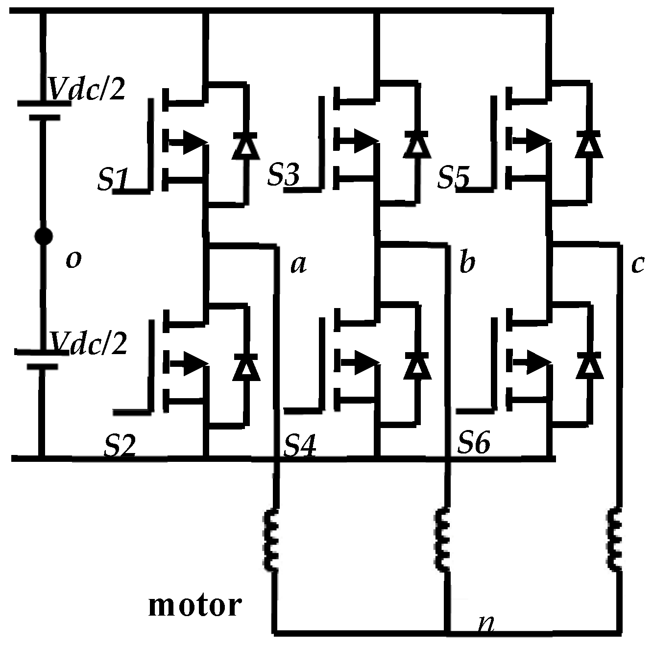
2.2. Three-Phase Vector Control Inverter

The inverter converts a direct current voltage DC into an alternating current voltage AC with variable frequency and amplitude. IGBTs often convert voltage from constant values and frequencies to variable values and frequencies. Its operating concept is based on modulating the source to generate the required AC signal frequency via suitably regulated switching, which is often PWM [23]. Figure 2 depicts a conventional voltage inverter with six controlled gates that use PWM and are supplied from a DC source.
This is a basic strategy that focuses on current control; it restricts the maximum current and is less susceptible to load changes. This approach regulates a current to follow a reference value determined from the stator currents component isdref, isqref, and the rotor angle (θ). If the current error between the reference and the actual value reaches the higher value (iref + ∆I), the switch arm of the inverter of the same phase starts to reduce the current values; if the error reaches the minimum value (iref − ∆I), the switch arm of the inverter of the same phase starts to increase the current values [24]. The motor-absorbed current and higher frequency of switches determine the bottom and upper boundaries of the hysteresis band (ΔI). A narrow band of hysteresis indicates a current comparable to a sine wave and an increasing switching frequency, and vice versa.
The voltage inverter types of the current references are employed in such a way as to make the phase currents of the motive periodic functions of rotor angle θ. They establish inside the air gap a magnet field whose magnetic axis is perpendicular to the magnetic field of the magnets, and they correspond to the electromotive forces generated by the magnets in these windings. This is the reason why when a reference current in a phase is out of its reference, one of the controllers has to switch the switches of each inverter arm and maintain the constant inside the hysteresis dead band of extent ΔI in Figure 1. The goal of vector control is to decouple the torque and flux components of the stator current [25]. This is achieved by aligning the stator current vector with the q-axis (torque-producing component) and controlling the d-axis current to regulate the flux [26].
The Control Objectives of VC are given to regulate the flux control: set i d = 0 for surface-mounted PMSMs and the torque control aims to control i q to regulate the torque. The main steps of VC are given as follows:
Clarke Transformation: convert the three-phase stator currents (ia, ib, ic) to two-phase stationary reference frame currents (iα, iβ) [26]:
i α = i a ,                           i β = 1 3 ( i a + 2 i b )
Park Transformation: convert the stationary reference frame currents (iα, iβ) to the rotating reference frame currents (id, iq):
i d = i α   c o s θ e + i β s i n θ e ,             i q = i α   s i n θ e + i β c o s θ e
where θ e is the electrical rotor position.
Current Control: use PI controllers to regulate i d and i q to their reference values i d * ,   i q * :
v d * = k p 1 i d * i d + k i 1 i d * i d d t ,             v q * = k p 2 i q * i q + k i 2 i q * i q d t
where k p 1 ,   k i 1 ,   k p 2 ,   k i 2 are the PI controller gains.
Inverse Park Transformation: convert the reference voltages ( v d * ,   v q * ) back to the stationary reference frame ( v α * ,   v β * ):
v α * = v d *   c o s θ e v q * s i n θ e ,         v β * = v d *   s i n θ e + v q * c o s θ e
Space Vector Modulation (SVM): generate the PWM signals for the inverter based on the reference voltages ( v α * ,   v β * ).

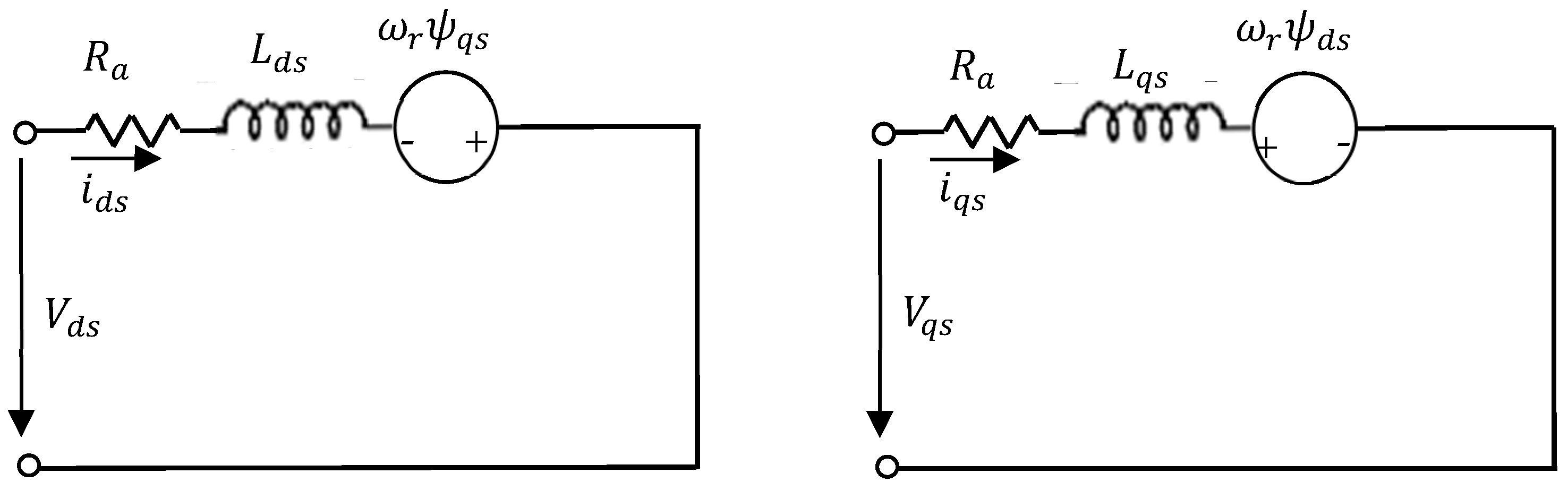
2.3. Dynamic Model of Salient Pole PMSMs

Figure 3 depicts the dq-axis electrical equivalent circuit of the stator and rotor sides for PMSMs. The PMSM sinusoidal voltages can be stated as follows [27]:
v a s = V m s i n ( ω t )
v b s = V m s i n ( ω t 120 ° )
v c s = V m s i n ( ω t 240 ° )
The reference frame along the dq-axis is deemed stationary. Hence, the voltage equations in the dq-axis may be recast as follows:
V q s = 3 2 k = 1 3 v k cos ( θ ( k 1 ) π 2 )
V d s = 3 2 k = 1 3 v k sin ( θ ( k 1 ) π 2 )
The current and flux equations of the stator and rotor are expressed in the q-axis and d-axis in Equations (10)–(13) as follows:
i q s = 1 L q s ψ q s
ψ q s = 1 s V q s R a i q s ω r ψ d s
i d s = 1 L d s ψ d s ψ m
ψ d s = 1 s V d s R a i d s + ω r ψ q s
The motor mechanical equations of total torque components of magnetic and reluctance torque and motor speed are as follows:
T e = 3 2 p ψ m i q s + ( L d s L q s ) i d s i q s
ω m = p 2 1 s 1 J T e T L B 2 p ω r
where p is the number of poles, ω r is the motor speed, and Ra is the stator resistance. Lds, Lqs, are the direct stator and quadrature stator inductances, J is the motor moment of inertia, TL is the mechanical load torque, and B is the viscous friction.
The total harmonic distortion (THD) in voltage and current can be calculated using the following equations:
T H D V = 100 × n 1 V n 2 V 1
T H D I = 100 × n 1 I n 2 I 1
where Vn and In are the RMS voltage and current values at the nth harmonic order, and V1 and I1 are the RMS voltage and current values at the fundamental frequency component.

2.4. Centrifugal Pump Model

The Pfleider–Peterman model is used to determine the head-flow rate (h-Q) of a centrifugal pump [28,29]. Variable speed family head can be conveyed around by taking the following quadratic equation [30]:
H = a 0 ω r 2 a 1 ω r Q a 2 Q 2
The coefficients of the h-Q curve are often provided by the manufacturers as a0, a1, and a2. The mechanical pump torque and power are calculated as follows:
P H = ρ g Q H
T p = k r ω r 2 + C s
The pump efficiency is the ratio of the hydraulic power imparted to the mechanical power of the shaft, and it is governed by [31]:
η p = ρ g H Q C ( 1 ω s t ω s ) 3 ω s
where H is the total height of the well (m), Q is the water flow (m3/s), g is the gravity (m/s2), ρ is the density (kg/m2), ωSt is the slip speed (rad/s), and ωS is the angular frequency of the supply (rad/s), respectively.

3. The Suggested Fuzzy Logic of PMSMs

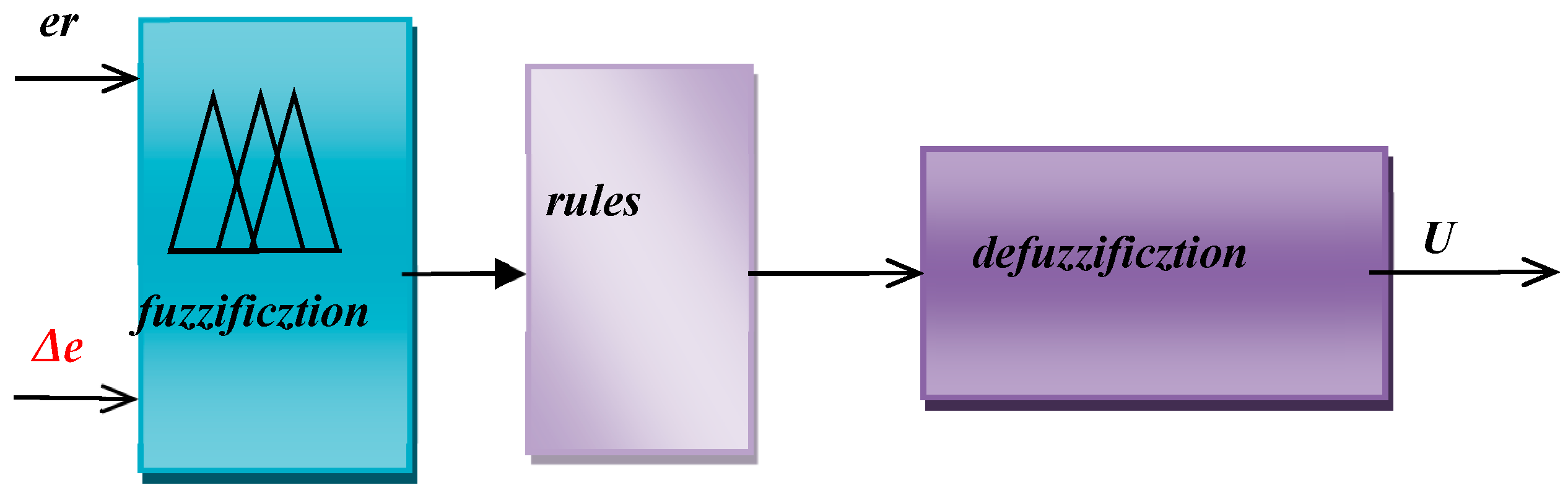
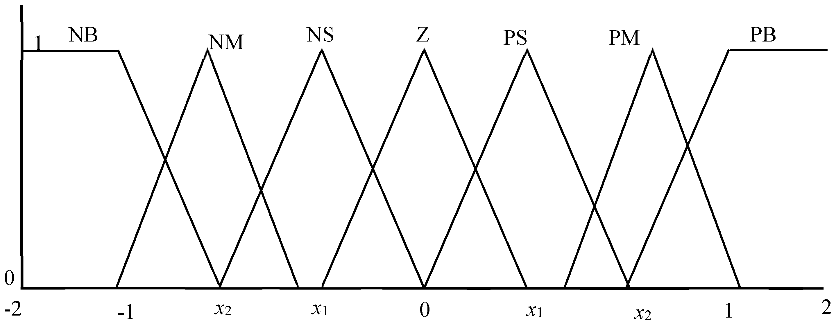
3.1. Auto-Tuned Fuzzy Logic Controller

The block diagram used for the auto-tuned speed control by FLC for the three-phase PMSM is shown in Figure 4.
FLC features two inputs: error (E) and error change (Δe), as well as one output that feeds the plant speed register of the vector control to the PWM inverter. Figure 4 shows the strategy utilized to get the desired speed value. For example, at stage A, the error is positive (actual speed), and the change error (last error) is negative, indicating that the reaction is going in the proper direction; so, the FLC will proceed in this direction. Using the same criterion as in stage B, the error is negative and the Δe is quite negative; hence, the reaction is going in the incorrect direction, so FLC will change direction to enter stage C until it reaches the appropriate speed.
In this research, the Mamdani technique in FPGA is employed to build FLC for a PMSM. FLC is divided into three parts: fuzzification, base rule, and defuzzification [32]. Figure 5 depicts the fuzzy set of the error, change error, and output entering the plant speed register, which has seven triangular memberships. Table 2 shows the knowledge base that defines the criteria for the intended relationship between the input and output variables for the membership functions.

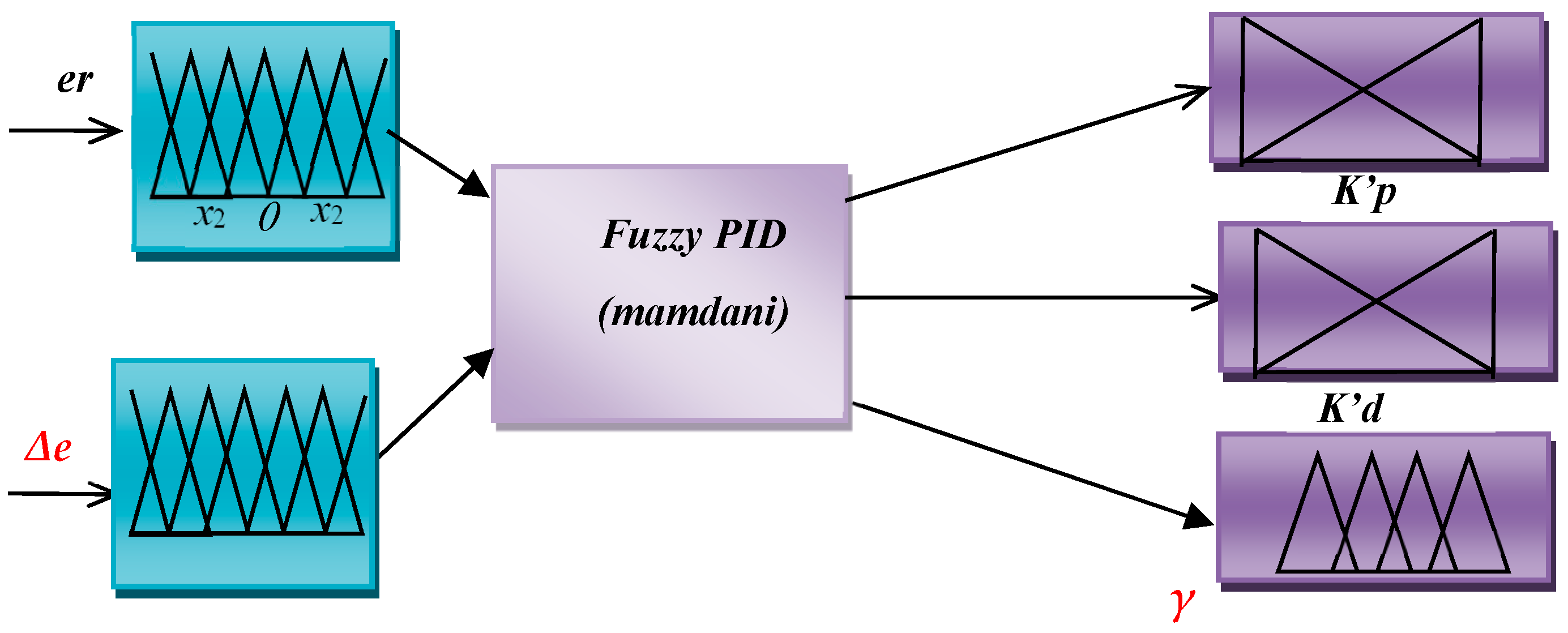
3.2. Fuzzy PID Controller
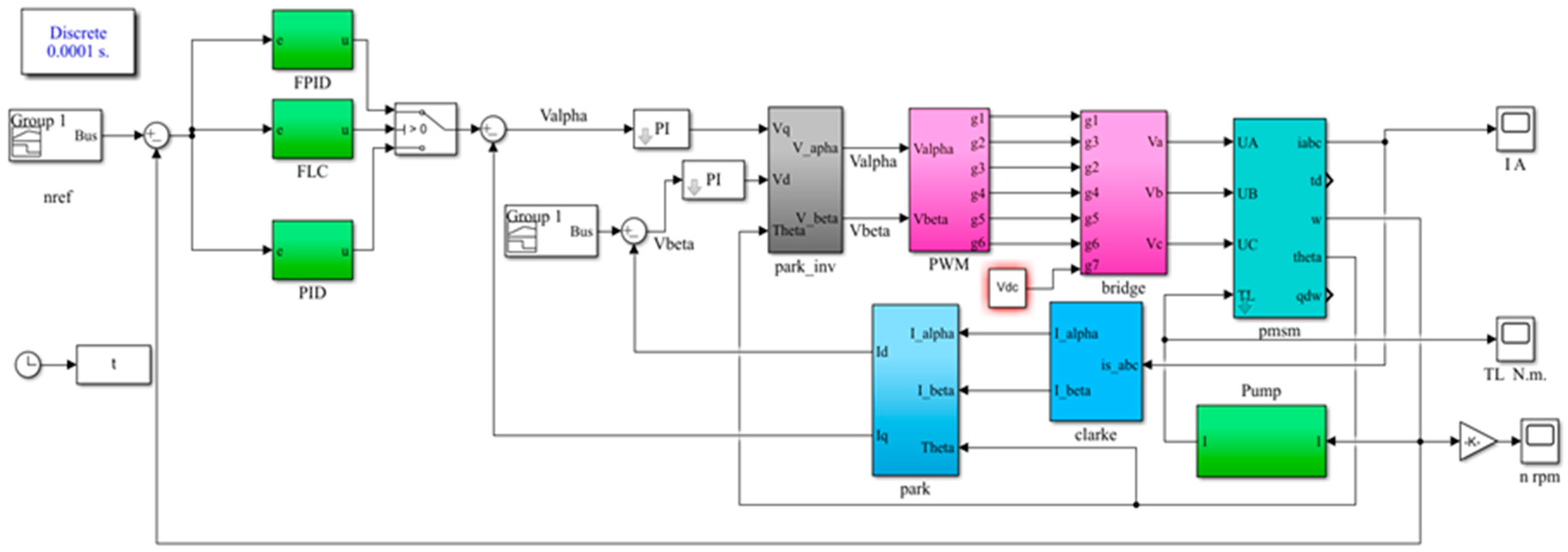
In this case, another solution is based on the blending of a PID controller and a fuzzy controller. Therefore, the parameters of the PID will be determined by using the online fuzzy controller. The fuzzy sets of the output coefficients Kp, Ki, and Kd are presented in Figure 6; practically, these parameters have three different fuzzy outputs. The inputs of the controller utilized include the error er(t) and change of error Δe(t). To overcome this error, the FPID controller changes the motor reference current ( i q * ) deviation in the following manner [30]:
e r ( t ) = ω r ω m
i q * = K p e r ( t ) + K i e r ( t ) d t + K d d Δ e ( t ) d t
Fuzzy PID supervisory involves the online application of fuzzy logic in the computation and continuous generation of PID parameters [33]. This procedure is demonstrated in Figure 1.
The fuzzy logic process includes three subsystems in Figure 6. The first subsystem converts a 0–1 value into fuzzy logic. The second is decided by applying fuzzy rules. The third converts fuzzy logic back into a 0–1 value. The process of choosing and employing the needed PID controller is performed in such a manner that maturation is the impact process, with the changes being controlled by the generic fuzzy system as a secondary controller correcting the parameters of the primary PID [34]. The speed error and its change enter the fuzzy system, and after creating the PID parameters, the PID generates the control signal and sends it to the switches of the inverter. It is suggested that Kp and Kd have been computed in the range of [Kpmin, Kpmax] and [Kdmin, Kdmax] [35]. For simplicity, the range of Kp and Kd in [0, 1] has been stated using the following relations [36]:
K p = ( K p K p m i n ) / ( K p m a x K p m i n )
K d = ( K d K d m i n ) / ( K d m a x K d m i n )
The differential time constant defines the integral time constant in the following way:
T i = γ T d
The integral coefficient Ki is determined by the following formula:
K i = K p γ T d = K p 2 γ K d
So, Reference [37] defined membership functions and fuzzy rules for fuzzy system coefficients, including K′p, K′d, γ, er, and Δe. The fuzzy system generates K′p, K′d, and γ, which determine the PID coefficients using these equations [37]:
K p = K p m a x K p m i n K p + K p m i n
K d = K d m a x K d m i n K d + K d m i n
K i = K p 2 γ K d
This turns input data into appropriate language values, as depicted in Figure 4. The controller receives two inputs: the error and the rate at which the error signals change. For the system under study, the universe of discourse for both e(t) and Δe(t) may be normalized from [−1, 1] and are referred to in the rules bases as {NG, ND, NM, Ze, PM, PM, PG}, and γ is referred to in the rules bases as {BG, LM, SM, RG}.
Figure 6 depicts the inputs and outputs of fuzzy logic control. The control rules of a fuzzy PID controller integrate fuzzy logic with traditional PID (Proportional-Integral-Derivative) control. Unlike classic PID controllers that use fixed gains (Kp, Ki, Kd), fuzzy PID controllers dynamically adjust these gains or directly determine the control output using fuzzy logic rules. Table 3 verifies the simplicity of the rule. Mandarin gold has the identical seven linguistic labels for input er and seven rules for input Δe. The rule base measures 7 × 7.
The control rules determine a fuzzy logic controller’s output state or choice. The center of gravity methodology is fuzzified in the proposed fuzzy control, and Mamdani’s max–min method is used for inference. As a result, seven fuzzy sets—seven mathematical functions—were identified as errors and given the designations Z, PS, PM, PB, NB, NM, and NS. For example, Equation (29) produces the group composition indicated as NS [38].
I F   e r t > 0             o r             e r t > x 1             t h e n           y t = 0 I F   e r t > x 1                         t h e n           y t = 3   e r ( t ) e l s e               y t = 3   e r t + 2
The change error for the O-membership error is given in [39] as follows:
I F   c e t < x 1             o r             c e t > x 1             t h e n           y t = 0 I F   Δ e t < 0                         t h e n           y t = 3   Δ e t + 1 e l s e               y t = 3   Δ e t + 1
A fuzzy logic controller with a MIN function was designed to find the smallest value between the membership of the two inputs, the er and Δe. This controller reflects the AND operator, which connects many fuzzy functions.
I F     e r   i s   N S     a n d   Δ e   i s   P S   t h e n   k p             i s             M k d             i s             G γ               i s             4
Increasing the action of integral control can result in a lesser value for the coefficient γ. The massive maximum point must be stopped at point b1. To reduce overshoot, Kd′ should be negative and Kp′ should be small due to the change in mistake regarding the reference point. γ should be big to minimize integral control action [40]. Based on the previously described mathematical model of the magnetic reluctance motor-driven water-pumping-system components optimized by PID, FLC, and FPID, MATLAB/Simulink: 2018 was employed to compare the results from the three cases.

4. Applications

A PMSM was utilized to show the efficacy of the proposed fuzzy control and fuzzy PID speed control systems. It was applied to a coupled PMSM-pumping-system model in MATLAB/Simulink: 2018 the solver is ode4 Runge–Kutta and the fixed step size is at 1 × 10⁻⁴ s, as seen in Figure 7.
The processing system simulates various loading conditions while running at varied speeds. The vector method is also used to create the FPID, which is paired with a VPWM inverter to power the PMSM and regulate torque and speed. The VPWM is based on PWM and uses the FPID output as the reference speed. As shown in Figure 8, the loading behavior during variable-speed operation can be specified. Figure 8 demonstrates the many situations of centrifugal pump PMSM loading that are optimized utilizing PID, fuzzy logic, and FPID controllers. Six inspection periods can be collected following sequential operating circumstances, as illustrated in Table 4. Table 5 shows the PMSM parameter data [27].
This paper employed the center of gravity approach. Figure 7 depicts the Simulink block diagram of the fuzzy speed controller for three-phase induction motors. The controller was evaluated using a Simulink motor module in MATLAB, with full load applied to the rotor after 3.5 s of operation. After 4 s, the target input speed was quickly reduced to half of its rating speed. Figure 9 depicts the fuzzy controller’s results. Figure 9, Figure 10, Figure 11, Figure 12, Figure 13 and Figure 14 show the simulation results for the system under consideration, which is made up of a PMSM connected with a VPWM inverter and a centrifugal pump. Figure 8 depicts the varied load values of the centrifugal pump, whose control was changed using a PID (Kp = 7.5, ki = 10, Kd = 0.00135), tuned by a trial-and-error method, and the performance was also enhanced with FLC and FPID, as well as PMSM speed tracking at various reference speeds. In this case, the FPID controller performed better in steady-state and low-error conditions. The findings reveal that the FPID achieves maximum speed quicker than FLC and PID.
Figure 9a depicts the motor’s speed performance under various operating situations while utilizing the PID, FLC to change speed. Figure 9a depicts the initial zooming inner graph controlled by FLC and PID, which took around 0.3 to 0.7 s to complete. With a loading torque of 5.9 N.m., this figure indicates that the speed error caused by the load using PID was 105.4 rpm, and the speed oscillation was 16 rpm, but the speed error when using FLC was 43.4 rpm and speed oscillation 3 rpm. Figure 9a depicts the second zooming inner graph controlled by PID and FLC, which took around 2 to 2.5 s to complete. With a loading torque of 3.5 N.m., this figure indicates that the speed error caused by the load using PID was 27 rpm, but the speed oscillation was 14 rpm, and the speed error when using FLC was 16 rpm and speed oscillation 4 rpm.
Figure 9b depicts the motor’s speed performance under various operating situations while utilizing PID and FPID to change speed. Figure 9b depicts the initial zooming inner graph controlled by FPID and PID, which took around 0.3 to 0.7 s to complete. With a loading torque of 5.9 N.m., this figure indicates that the speed error caused by the load using PID was 105.4 rpm, and the speed oscillation was 16 rpm, but the speed error when using FPID was 25.4 rpm and speed oscillation 8 rpm. Figure 9b depicts the second zooming inner graph controlled by PID and FPID, which took around 2 to 2.5 s to complete. With a loading torque of 3.5 N.m., this figure indicates that the speed error caused by the load using PID was 27 rpm, but the speed oscillation was 14 rpm; the speed error when using FPID was 13 rpm and speed oscillation 5 rpm.
Figure 10 and Figure 11 show the THD for both the voltage and current waveforms at an instant of 0.5 s. Figure 10a shows that employing FLC improves inverter performance by decreasing the voltage’s THD values. This is particularly apparent at 0.5 s when the THD value using PID was 23.7% and the THD value using FLC was 18.27%, resulting in an estimated 22.9% decrease rate. Figure 10b shows that employing FPID improves inverter performance by decreasing the voltage’s THD values. This is particularly apparent at 0.5 s when the THD value using PID was 23.7% and the THD value using FPID was 17.6%, resulting in an estimated 25.7% decrease rate. Figure 11a shows that employing FLC improves the inverter’s performance by decreasing the average THD value of the current. This is notably true at 0.5 s when the THD value with PID was 22.1% and the FLC value was 25.3%. Figure 11b shows that employing FPID improves the inverter’s performance by decreasing the average THD value of the current. This is notably true at 0.5 s when the THD value with PID was 22.11% and the FPID value was 18.07%.
Table 6 displays the THD values for current and voltage during various operating periods as the motor reaches a steady state. These values are based on the voltage frequency and their respective values, as shown in Figure 12. The table also shows that the proposed method gives lower THD values in most operating periods and outperforms other approaches. Figure 12a,b shows how the stator voltage of a PMSM controlled by PID, FLC, and FPID may disclose various crucial distinctions and features over time. The comparison of stator voltage changes over time for PMSM controlled by PID, FLC, and FPID demonstrates the benefits of FPID in terms of responsiveness, stability, and adaptability. While PID control may be a simpler solution, FPID’s ability to include fuzzy logic allows for superior performance in dynamic conditions, resulting in higher motor efficiency and dependability.
According to Figure 13, the stator current rises gradually to reach its maximum value at the start moment and then decreases at a steady state speed of 2000 rpm. Figure 13a,b shows the current change in the six periods for each PID, FLC, and FPID. These figures show that when using the PID at the beginning of each stage, the current increase is large compared to that of FLC or FPID.
Figure 14 depicts the values of the variables Kp, Kd, and Ki as a function of pump speed and mechanical load, demonstrating how PID may enhance the system’s operating performance. The online changes in the three parameters at various speeds and load ranges are as follows: Kp from 6.2 to 7, Kd from 0.0018 to 0.0028, and Ki from 1 to 3.5. Table 7 shows the statistical analysis of motor speed at different operating periods.
The performance figures and Table 7 provide a comparison of the outcomes of the PID controller, fuzzy logic, and the FPID controller, in which PID requires manual tuning. FPID controllers have the following extrapolated advantages over fuzzy logic and PID controllers:
  • When the FLC and FPID controllers are used, the steady-state error (SSE), speed overshoot (OS), and undershoot of periods 1–6 are reduced.
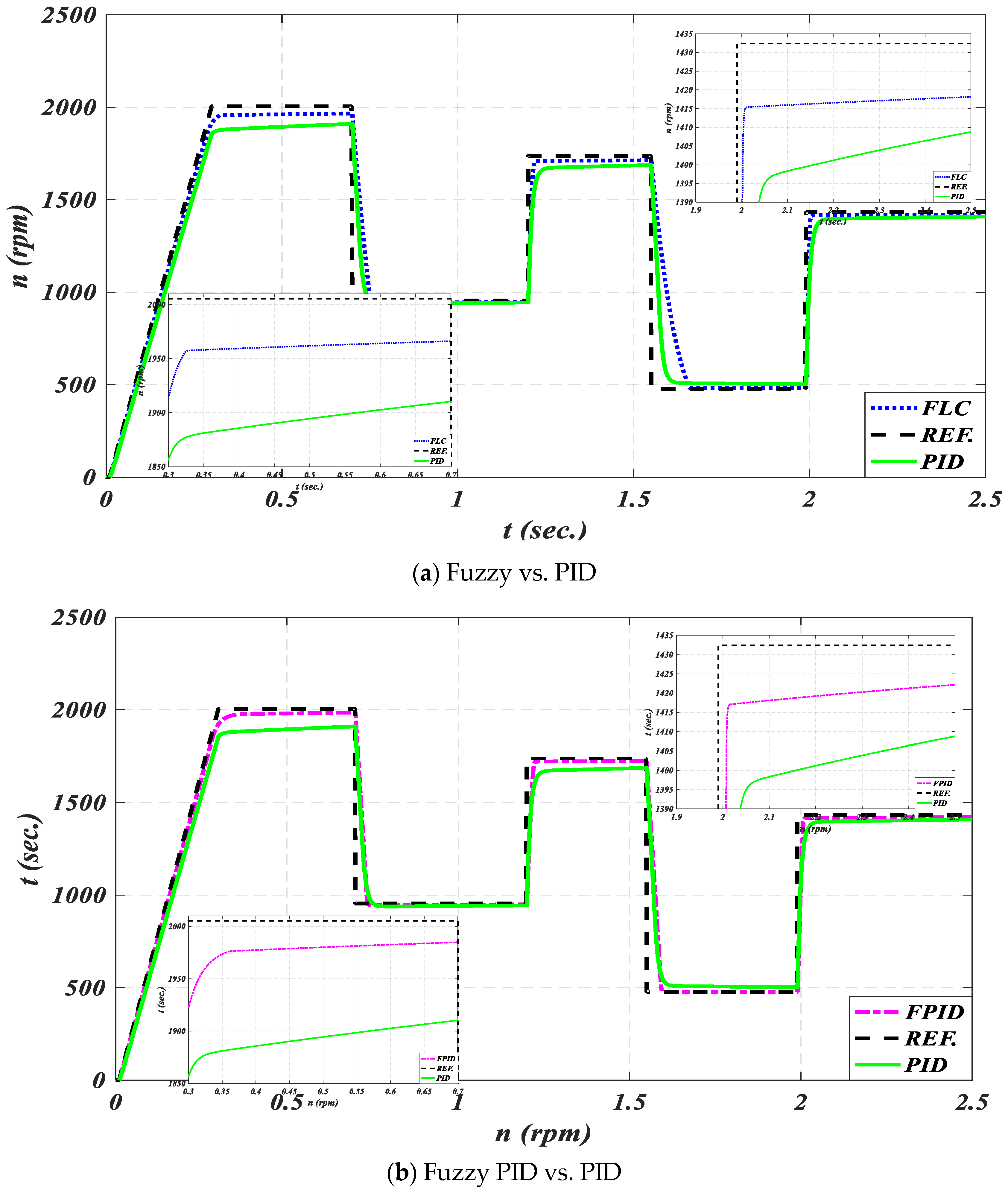
  • In period 2, at a pump torque of 5.9 N.m., the speed error caused by the load using PID is 105.4 rpm, and the speed oscillation is 16 rpm; the speed error when using FLC is 46.4 rpm and speed oscillation is 3 rpm; and the speed error when using FPID is 25.4 rpm and the speed oscillation is 8 rpm. Figure 9a depicts the second zooming inner graph controlled by FLC and PID, which takes around 2 to 2.5 s to complete. With a loading torque of 3.5 N.m., this figure indicates that the speed error caused by the load using PID is 27 rpm, and the speed oscillation is 14 rpm; the speed error when using FLC is 16 rpm and speed oscillation 4 rpm; and the speed error when using FPID is 13 rpm, and the speed oscillation is 5 rpm.
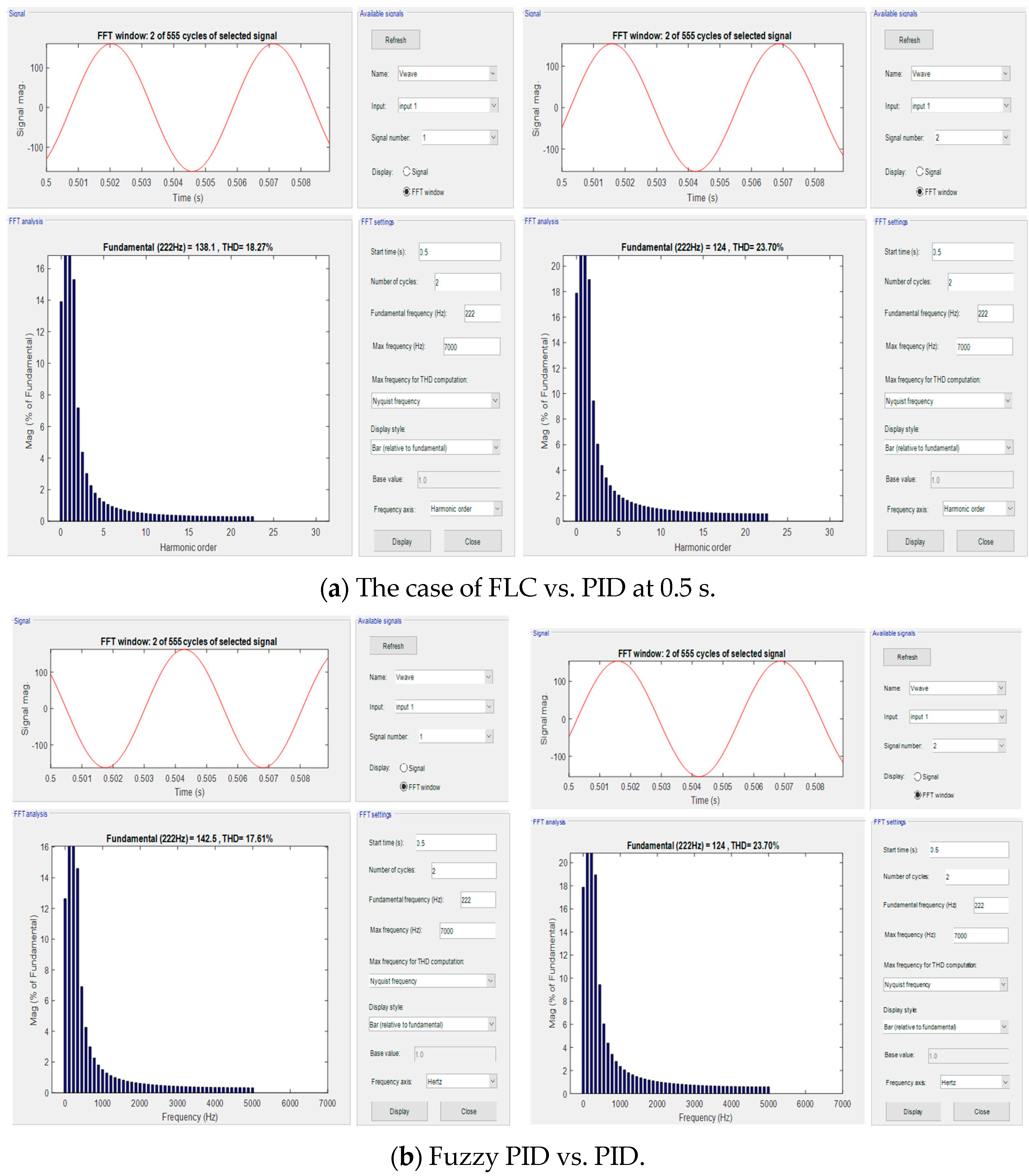
  • In comparison, the THD in voltage values in period 4, between the PID controller, FLC, and FPID, are 21.19%, 6.59%, and 3.6%, respectively.
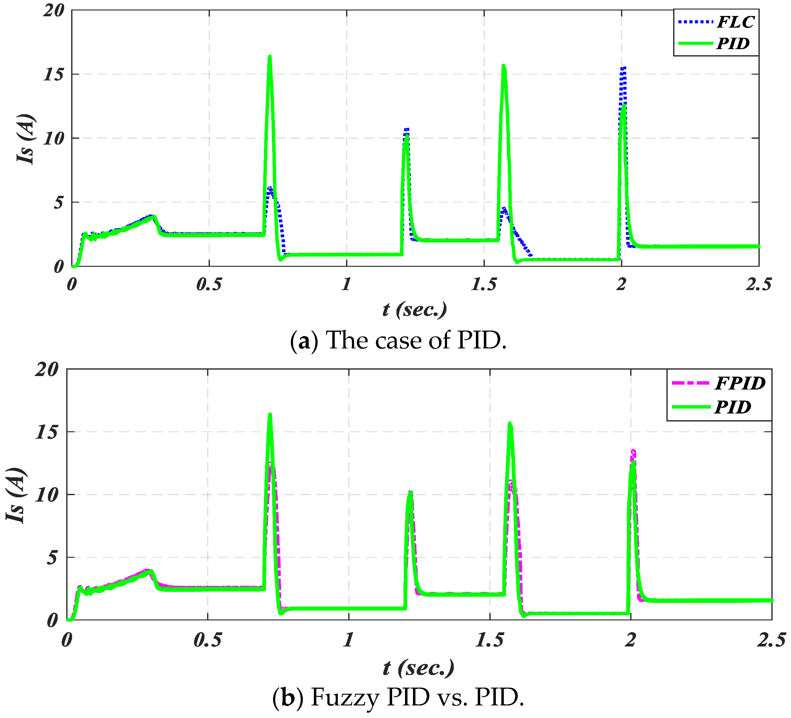
  • In comparison, the starting current values in period 5, between the PID controller, FLC, and FPID, are 15.8 A, 5 A, and 12 A, respectively.

5. Conclusions and Future Trends

The application of PID, fuzzy, and fuzzy PID controllers to enhance the speed control of vector PWM for PMSMs in pumping systems demonstrates significant improvements in performance and efficiency. The salient pole rotor design inherently provides both magnetic and reluctant torque, allowing for enhanced torque density and efficiency. Traditional PID controllers provide a solid foundation for speed control, offering stability and responsiveness. However, they may struggle with the non-linearities and varying operating conditions typical in pumping systems. FLC introduces a more flexible approach by accommodating uncertainties and non-linear behaviors. It can adapt to changing conditions without requiring precise mathematical models, leading to improved performance in speed regulation and system robustness. The integration of fuzzy logic with PID control combines the strengths of both methods. FPID controllers can dynamically adjust the PID parameters based on the system’s current state, resulting in enhanced adaptability and an improved transient response. This hybrid approach effectively mitigates overshoot and settling time, leading to smoother operation and better speed tracking. Overall, the use of these control strategies in the vector PWM control of PMSMs for pumping systems not only enhances speed control accuracy but also improves energy efficiency and reduces current overshot and system reliability. While FPID controllers offer adaptability and robustness in the vector control of multi-phase induction motors, they come with significant drawbacks, including computational complexity, tuning difficulty, and performance limitations under extreme conditions. These challenges must be carefully addressed through optimization, hybridization, and advanced hardware to fully realize the potential of FPID in multi-phase motor drives.
One of the future trends is the development of machine learning techniques to optimize fuzzy rules for specific pumping system requirements. Also, another future development will combine FLC/FPID with other advanced control techniques like Model Predictive Control (MPC) or Sliding Mode Control (SMC) to enhance the overall performance of the PMSM. Added to the previous directions, developing and evaluating the proposed control strategy on a real-time PMSM-driven pumping system will aim at evaluating the application of the proposed control scheme at normal and load-varied conditions. An extension to the current study is to evaluate the motor performance under parameter variations, load disturbances, and fault conditions in comparison with conventional DTC and other advanced control methods. Another study will aim at studying the effect of the blade curvatures and lengths with fixed blade inlet and outlet angles on the pump performance, and in turn, the control strategies will be considered in the future.

Author Contributions

Conceptualization, M.I.A. and R.A.E.-S.; methodology, M.I.A.; software, M.I.A.; validation, R.A.E.-S., A.H. and F.A.; formal analysis, R.A.E.-S.; investigation, A.H. and F.A.; resources, M.I.A.; data curation, R.A.E.-S.; writing—original draft preparation, M.I.A.; writing—review and editing, A.H. and F.A.; visualization, A.H. and F.A.; supervision, M.I.A. and R.A.E.-S.; project administration, R.A.E.-S.; funding acquisition, A.H. and F.A. All authors have read and agreed to the published version of the manuscript.

Funding

This research project was funded via the Deanship of Scientific Research (DSR), King Abdulaziz University, Jeddah, Kingdom of Saudi Arabia, under grant number (D-056-829-1439). The authors wish to express their gratitude to DSR for their technical and financial support.

Data Availability Statement

The data of this study are available upon request from the corresponding author.

Conflicts of Interest

The authors have no conflicts of interest.

References

  1. Kalyan, H.; Syal, P. Design of Permanent Magnet Synchronous Motor for Efficient Solar Pumping System. In International Conference on Emerging Electronics and Automation; Springer: Singapore, 2024; pp. 427–438. [Google Scholar] [CrossRef]
  2. Jin, X.; Zhou, L.; Lang, T.; Jiang, Y. Low-Voltage Water Pump System Based on Permanent Magnet Synchronous Motor. Electronics 2024, 13, 3674. [Google Scholar] [CrossRef]
  3. Candelo-Zuluaga, C.; Riba, J.-R.; Espinosa, A.G.; Tubert, P. Customized PMSM Design and Optimization Methodology for Water Pumping Applications. IEEE Trans. Energy Convers. 2022, 37, 454–465. [Google Scholar] [CrossRef]
  4. Bao, R.; Wang, Q.; Wang, T. Energy-Saving Trajectory Tracking Control of a Multi-Pump Multi-Actuator Hydraulic System. IEEE Access 2020, 8, 179156–179166. [Google Scholar] [CrossRef]
  5. Fu, C.; Ma, X.; Zhang, L. Fuzzy-PID Strategy Based on PSO Optimization for pH Control in Water and Fertilizer Integration. IEEE Access 2022, 10, 4471–4482. [Google Scholar] [CrossRef]
  6. Almadi, A.I.M.; Al Mamlook, R.E.; Almarhabi, Y.; Ullah, I.; Jamal, A.; Bandara, N. A Fuzzy-Logic Approach Based on Driver Decision-Making Behavior Modeling and Simulation. Sustainability 2022, 14, 8874. [Google Scholar] [CrossRef]
  7. Neugebauer, M.; Akdeniz, C.; Demir, V.; Yurdem, H. Fuzzy logic control for watering system. Sci. Rep. 2023, 13, 18485. [Google Scholar] [CrossRef] [PubMed]
  8. Oussama, M.; Abdelghani, C.; Lakhdar, C. Efficiency and robustness of type-2 fractional fuzzy PID design using salps swarm algorithm for a wind turbine control under uncertainty. ISA Trans. 2022, 125, 72–84. [Google Scholar] [CrossRef]
  9. Alkuhayli, A.; Noman, A.M.; Al-Shamma’a, A.A.; Abdurraqeeb, A.M.; Alharbi, M.; Hussein Farh, H.M.; Qamar, A. Enhancing Photovoltaic-Powered DC Shunt Motor Performance for Water Pumping through Fuzzy Logic Optimization. Machines 2024, 12, 442. [Google Scholar] [CrossRef]
  10. Tahami, H.; Saberi, S.; Ali, B.M.; AbdulAmeer, S.; Hussein, A.H.A.; Chaoui, H. A Robust Hꝏ-Based State Feedback Control of Permanent Magnet Synchronous Motor Drives Using Adaptive Fuzzy Sliding Mode Observers. Actuators 2024, 13, 307. [Google Scholar] [CrossRef]
  11. Jin, F.; Wan, H.; Huang, Z.; Gu, M. PMSM Vector Control Based on Fuzzy PID Controller. J. Phys. Conf. Ser. 2020, 1617, 012016. [Google Scholar] [CrossRef]
  12. Orazbayev, B.; Tanirbergenova, A.; Orazbayeva, K.; Berikbaeva, M.; Kaliyeva, S.; Kurmangaziyeva, L.; Makhatova, V. Decision Making for Control of the Gasoline Fraction Hydrotreating Process in a Fuzzy Environment. Processes 2024, 12, 669. [Google Scholar] [CrossRef]
  13. Solangi, Y.A.; Longsheng, C.; Shah, S.A.; Alsanad, A.; Ahmad, M.; Akbar, M.A.; Gumaei, A.; Ali, S. Analyzing Renewable Energy Sources of a Developing Country for Sustainable Development: An Integrated Fuzzy Based-Decision Methodology. Processes 2020, 8, 825. [Google Scholar] [CrossRef]
  14. El-Sehiemy, R.A.; Aleem, S.H.E.A.; Abdelaziz, A.Y.; Balci, M.E. A new fuzzy framework for the optimal placement of phasor measurement units under normal and abnormal conditions. Resour.-Effic. Technol. 2017, 3, 542–549. [Google Scholar] [CrossRef]
  15. Kudinov, Y.I.; Kolesnikov, V.A.; Pashchenko, F.F.; Pashchenko, A.F.; Papic, L. Optimization of Fuzzy PID Controller’s Parameters. Procedia Comput. Sci. 2017, 103, 618–622. [Google Scholar] [CrossRef]
  16. Kumar, R.; Baz, A.; Alhakami, H.; Alhakami, W.; Agrawal, A.; Khan, R.A. A hybrid fuzzy rule-based multi-criteria framework for sustainable-security assessment of web application. Ain Shams Eng. J. 2021, 12, 2227–2240. [Google Scholar] [CrossRef]
  17. Raj, F.V.A.; Kannan, V.K. Particle Swarm Optimized Deep Convolutional Neural Sugeno-Takagi Fuzzy PID Controller in Permanent Magnet Synchronous Motor. Int. J. Fuzzy Syst. 2022, 24, 180–201. [Google Scholar] [CrossRef]
  18. Tahhan, A.; Temurtaş, F. Enhanced Fuzzy Logic Control Model and Sliding Mode Based on Field Oriented Control of Induction Motor. World J. Eng. Technol. 2024, 12, 65–79. [Google Scholar] [CrossRef]
  19. Khanh, P.Q.; Anh, H.P.H. Advanced PMSM speed control using fuzzy PI method for hybrid power control technique. Ain Shams Eng. J. 2023, 14, 102222. [Google Scholar] [CrossRef]
  20. Bouguenna, I.F.; Tahour, A.; Kennel, R.; Abdelrahem, M. Multiple-Vector Model Predictive Control with Fuzzy Logic for PMSM Electric Drive Systems. Energies 2021, 14, 1727. [Google Scholar] [CrossRef]
  21. Wang, T.; Wang, H.; Wang, C.; Hu, H. A novel PID controller for BLDCM speed control using dual fuzzy logic systems with HSA optimization. Sci. Rep. 2022, 12, 11316. [Google Scholar] [CrossRef]
  22. Acharya, D.; Das, D.K. A novel PID controller for pressure control of artificial ventilator using optimal rule based fuzzy inference system with RCTO algorithm. Sci. Rep. 2023, 13, 9281. [Google Scholar] [CrossRef]
  23. Kolano, K. New Method of Vector Control in PMSM Motors. IEEE Access 2023, 11, 43882–43890. [Google Scholar] [CrossRef]
  24. Yuvaraja, T.; Ramya, K. Vector control of PMSM take over by photovoltaic source. Appl. Comput. Electromagn. Soc. J. (ACES) 2018, 33, 228–231. [Google Scholar]
  25. Zhang, X.; Ren, M.; Wang, H.; Jin, L. Simulation Study on Dynamic Characteristics of the Chain Drive System for Mining Scraper Conveyor Driven by the Permanent Magnet Synchronous Motor. Processes 2024, 12, 165. [Google Scholar] [CrossRef]
  26. Zhang, P.; Shi, Z.; Yu, B.; Qi, H. Research on a Sensorless ADRC Vector Control Method for a Permanent Magnet Synchronous Motor Based on the Luenberger Observer. Processes 2024, 12, 906. [Google Scholar] [CrossRef]
  27. Hamida, M.A.; Abdelwanis, M.I.; El-Sehiemy, R. Parameter Estimation of Permanent Magnet Synchronous Machines Using Particle Swarm Optimization Algorithm. Rev. Roum. Sci. Tech.—Série Électrotechnique Énergétique 2022, 67, 377–382. [Google Scholar]
  28. Betka, A.; Moussi, A. Performance optimization of a photovoltaic induction motor pumping system. Renew. Energy 2004, 29, 2167–2181. [Google Scholar] [CrossRef]
  29. Makhlouf, M.; Messai, F.; Benalla, H. Vectorial Command of Induction Motor Pumping System Supplied by a Photovoltaic Generator. J. Electr. Eng. 2011, 62, 3–10. [Google Scholar] [CrossRef]
  30. Abdelwanis, M.I.; El-Sehiemy, R.A. A Fuzzy-Based Controller of a Modified Six-Phase Induction Motor Driving a Pumping System. Iran. J. Sci. Technol.-Trans. Electr. Eng. 2019, 43, 153–165. [Google Scholar] [CrossRef]
  31. Milošević, M.; Radić, M.; Rašić-Amon, M.; Litričin, D.; Stajić, Z. Diagnostics and Control of Pumping Stations in Water Supply Systems: Hybrid Model for Fault Operating Modes. Processes 2022, 10, 1475. [Google Scholar] [CrossRef]
  32. Wang, C.; Zhu, Z.Q. Fuzzy Logic Speed Control of Permanent Magnet Synchronous Machine and Feedback Voltage Ripple Reduction in Flux-Weakening Operation Region. IEEE Trans. Ind. Appl. 2020, 56, 1505–1517. [Google Scholar] [CrossRef]
  33. Shanthi, R.; Kalyani, S.; Devie, P.M. Design and performance analysis of adaptive neuro-fuzzy controller for speed control of permanent magnet synchronous motor drive. Soft Comput. 2021, 25, 1519–1533. [Google Scholar] [CrossRef]
  34. Zhang, B.; Niu, P.; Guo, X.; He, J. Fuzzy PID control of permanent magnet synchronous motor electric steering engine by improved beetle antennae search algorithm. Sci. Rep. 2024, 14, 2898. [Google Scholar] [CrossRef]
  35. Yin H, Yi W, Wu J, Wang K, Guan JAdaptive Fuzzy Neural Network PID Algorithm for BLDCM Speed Control System. Mathematics 2022, 10, 118. [CrossRef]
  36. Abdelwanis, M.I.; El-Sehiemy, R.A. Performance enhancement of split-phase induction motor by using fuzzy-based PID controller. J. Electr. Eng. 2019, 70, 103–112. [Google Scholar] [CrossRef]
  37. Abdelwanis, M.I.; El-Sousy, F.F.M.; Ali, M.M. A Fuzzy-Based Proportional–Integral–Derivative with Space-Vector Control and Direct Thrust Control for a Linear Induction Motor. Electronics 2023, 12, 4955. [Google Scholar] [CrossRef]
  38. Abdelwanis, M.I. Optimizing the performance of six-phase induction motor-powered electric vehicles with fuzzy-PID and DTC. Neural Comput. Appl. 2025, 1–14. [Google Scholar] [CrossRef]
  39. Hermassi, M.; Krim, S.; Kraiem, Y.; Hajjaji, M.A.; Alshammari, B.M.; Alsaif, H.; Alshammari, A.S.; Guesmi, T. Design of Vector Control Strategies Based on Fuzzy Gain Scheduling PID Controllers for a Grid-Connected Wind Energy Conversion System: Hardware FPGA-in-the-Loop Verification. Electronics 2023, 12, 1419. [Google Scholar] [CrossRef]
  40. Chamanpira, M.; Ghahremani, M.; Dadfar, S.; Khaksar, M.; Rezvani, A.; Wakil, K. A novel MPPT technique to increase accuracy in photovoltaic systems under variable atmospheric conditions using Fuzzy Gain scheduling. Energy Sources Part A Recovery Util. Environ. Eff. 2021, 43, 2960–2982. [Google Scholar] [CrossRef]
Figure 1. The suggested fuzzy PID PMSM schematic diagram.
Processes 13 01393 g001
Figure 2. Three-phase VSI circuit.
Processes 13 01393 g002
Figure 3. Dq-axis electrical circuit of PMSMs.
Processes 13 01393 g003
Figure 4. FLC controller for the three-phase PMSM.
Processes 13 01393 g004
Figure 5. Error, change error, output entering to plant speed register set of FLC.
Processes 13 01393 g005
Figure 6. Block diagram of fuzzy logic control.
Processes 13 01393 g006
Figure 7. MATLAB/Simulink schematic diagram of PMSM.
Processes 13 01393 g007
Figure 8. Pump torque characteristics.
Processes 13 01393 g008
Figure 9. PMSM pump speed characteristics.
Processes 13 01393 g009
Figure 10. THD of stator voltage at 0.5 s.
Processes 13 01393 g010
Figure 11. THD of current characteristics.
Processes 13 01393 g011
Figure 12. PMSM input rms voltage.
Processes 13 01393 g012
Figure 13. MPPIM input rms stator current.
Processes 13 01393 g013
Figure 14. Self-tunning parameters of PID using fuzzy logic control (Kp, Ki, and Kd).
Processes 13 01393 g014
Table 1. Merits and demerits of various control-based strategies applied to PMSMs.
Controller TypeDescriptionAdvantagesLimitationsApplications
Scalar Control Volts/Hertz (V/f)This control method adjusts voltage and frequency proportionally to motor speed.Cost-effective,
simple design,
reliable for applications.
Limited for dynamic loads, lacks precise speed and torque control.Centrifugal pumps, fans, conveyors.
Sensorless VectorEstimates motor speed and torque without needing a physical sensor.Better torque control and efficiency compared to V/f, moderate cost.Accuracy depends on motor characteristics; not suitable for applications needing precise control.Electric vehicles, HVAC systems, wind turbines.
Field-Oriented Control (FOC)Advanced method maintaining precise control over motor magnetic fields for optimal performance.High efficiency, excellent torque control at low speeds, and precise motor operation.Higher cost, complexity requires careful setup and tuning.Elevators, robotics, CNC machines, electric vehicles.
Direct Torque Control (DTC)Provides direct control of motor torque and flux without requiring modulation.Fast dynamic response, precise control, reduced energy losses.Complex algorithm, may require specialized hardware.Traction systems, industrial drives, high-performance drives.
PID ControllerUses proportional, integral, and derivative gains to maintain desired motor speed based on feedback.Ideal for maintaining steady flow or pressure, easy integration with control systems.Requires tuning for optimal performance; slower response in dynamic systems.Pressure pumps, HVAC systems.
Adaptive ControlAdjusts control parameters in real-time to optimize performance.High efficiency under varying loads, reduced energy consumption.High cost, complexity requires advanced software and hardware.High-performance drives, renewable energy systems, electric vehicles, aerospace variable-load pumping systems.
Table 2. Control base rules for Fuzzy controller.
ECENBNMNSZPSPMPB
NBNBNBNBNBNMNSZ
NMNMNMNSZPS
NSNMNSNSZPSPM
ZZPSPMPB
PSNMNSZPS
PMNSZPSPMPMPB
PBZPSPMPBPB
NB refers to Negative Big, NM denotes to Negative Medium, NS denotes to Negative Small, Z refers to Zero, PS refers to Positive Small, PM denotes to Positive Medium, and PB denotes Positive Big.
Table 3. The rules table of the suggested FPID controller [38].
erΔekpkdγerΔeKpkdγ
PG, NBNBBGSMPSPS, NMNBSMBGBG
NMNMSM
NSNSBG
ZZSMPS
PSPSBGSM
PMPMSM
PBPBBG
PM, NMNBSMBGSMZNBPB
NMBGNMBG
NSSMPSNSSM
ZZBG
PSPSSM
PMBGSMPMBG
PBPBPB
Table 4. The PMSM operation periods.
No.PeriodsDescription
FromTo
100.3 sec.Starting state
20.3 sec.0.7 sec.Normal speed (1200 rpm) at 5.9N.m
30.7 sec.1.2 sec.Reduced speed (1000 rpm) at 2 N.m.
41.2 sec.1.55 sec.Increase speed (2100 rpm), 4.6 N.m.
51.55 sec.1.99 sec.More speed amendment (500 rpm), 1 N.m.
61.99 sec.2.5 sec.Increase speed to (1400 rpm), 3.5 N.m.
Table 5. The electrical equivalent circuit parameters of PMSM [27].
Parameters MagnitudeParameters Magnitude
Stator voltage, Vph220 (V)Moment of inertia, J0.00609 (kg.m2)
Motor stator current 2.5 (A)Motor-rated torque 5.8 (N.m)
stator q-axis inductance, Lqs0.0038 (H)Permanent magnet flux, ψm 0.14 (Wb.turns)
Stator d-axis inductance, Lds0.0038 (H)Saliency ratio2
Stator resistance, Rs0.45 (Ω)No. of poles, p (poles)6
Table 6. THD of steady state period of current and voltage.
Frequency HzTime sec.% THD of Current% THD of Voltage
PeriodPIDFCFPIDPIDFCFPID
0.3–0.72220.522.1125.3718.0723.718.2717.61
0.7–1.29312.955.713.0853.075.753.91
1.2–1.551721.47.052.360.057.962.320.02
1.55–1.99471.718.045.093.3321.196.593.6
1.99–2.51432.33.752.091.183.262.341.07
Table 7. Statistical analysis of motor speed and current in deferent period of operations.
ControllerPeriodSpeed (rpm)Current (A)
2345623456
PIDSteady state19009401680504.51405.42.50.92.040.531.55
FLC1962945.51711480.51416.42.510.92.060.531.56
FPID19809491725477.751419.42.60.92.070.521.54
PIDOscillating range16684140.0615.891511.25
FLC332140.158.2415.24
FPID82.540.650.06129.1813
PIDRise time (sec.)0.310.91.41.82.050.350.81.31.662.08
FLC0.3250.751.231.662.010.350.7751.251.682.04
FPID0.360.681.221.652.010.370.761.251.6152.03
Disclaimer/Publisher’s Note: The statements, opinions and data contained in all publications are solely those of the individual author(s) and contributor(s) and not of MDPI and/or the editor(s). MDPI and/or the editor(s) disclaim responsibility for any injury to people or property resulting from any ideas, methods, instructions or products referred to in the content.

