Article

Calcium Precipitates as Novel Agents for Controlling Steam Channeling in Steam Injection Processes for Heavy Oil Recovery

1
Sinopec, Petroleum Development Center Shengli Oilfield, Dongying 257000, China
2
College of Chemistry and Chemical Engineering, China University of Petroleum (East China), Qingdao 266580, China
3
School Petroleum Engineering, China University of Petroleum (East China), Qingdao 266580, China
*
Author to whom correspondence should be addressed.
Processes 2025, 13(5), 1319; https://doi.org/10.3390/pr13051319
Submission received: 17 March 2025 / Revised: 8 April 2025 / Accepted: 14 April 2025 / Published: 25 April 2025
(This article belongs to the Section Energy Systems)

Abstract

:
Unconventional heavy oil reservoirs are particularly susceptible to steam breakthrough, which significantly reduces crude oil production. Profile control is a crucial strategy used for stabilizing oil production and minimizing production costs in these reservoirs. Conventional plugging agent systems used in the thermal recovery of heavy oil currently fail to meet the high-temperature, high-strength, and deep profile control requirements of this process. Precipitation-type calcium salt blocking agents demonstrate long-term stability at 300 °C and concentrations up to 250,000 mg/L, making them highly effective for profile control and channeling blockage during the steam injection stages of heavy oil recovery. This study proposes two types of precipitation-type calcium salt blocking agents: CaSO4 and CaCO3 crystals. The precipitation behavior of these agents was investigated, and their dynamic growth patterns were examined. The calcium sulfate blocking agent exhibits a slower crystal precipitation rate, allowing for a single-solution injection, while the calcium carbonate blocking agent precipitates rapidly, requiring a dual-solution injection. Both systems incorporate scale inhibitors to delay the growth of calcium salt crystals, which aids in deep profile control. Through microscopic visualization experiments, the micro-blocking characteristics of the calcium salt blocking agent systems within pores were compared, elucidating the blocking positions of the precipitated calcium salts under porous conditions. Calcium sulfate crystals preferentially precipitate in and block larger pore channels, whereas calcium carbonate crystals are more evenly distributed throughout the pore channels, reducing the reservoir’s heterogeneity. The final single-core displacement experiment demonstrated the sealing properties of the precipitation-type calcium salt blocking agent systems. The developed precipitation-type calcium salt blocking agent systems exhibit excellent profile control performance.

Graphical Abstract

1. Introduction

Unconventional oil resources comprise approximately two-thirds of the world’s total crude oil reserves, with heavy oil resources constituting over 30% of these unconventional reserves. China’s proven geological reserves of heavy oil total 680 million tons. The large-scale, economically efficient development of heavy oil is critical for safeguarding national energy and strategic security [1,2]. Heavy oil is an unconventional oil and gas resource characterized by high viscosity and poor flowability. Upon undergoing intense oxidation, the components of heavy oil aggregate to form macromolecular structures, thereby complicating its development relative to conventional reservoirs and increasing its associated costs [3].
Heavy oil reservoir development technologies are primarily classified into thermal recovery and cold recovery methods [4,5,6,7]. Due to the substantial change in heavy oil’s viscosity with temperature, thermal recovery has emerged as the predominant and most effective development method. Steam injection techniques are effective in enhancing the recovery factor of reservoirs, facilitating high-yield heavy oil extraction [8,9,10]. However, during steam injection for heavy oil recovery, the heterogeneity of the reservoir and the differing flowabilities of steam and heavy oil cause high-temperature steam to preferentially flow along high-permeability layers and the upper sections of the reservoir. Dynamic variations in temperature, pressure, and permeability across different regions lead to low injection gas utilization and reduced steam flooding efficiency [11]. To optimize the effectiveness of thermal recovery in heavy oil, appropriate profile control is essential, making the need for efficient, temperature-resistant profile control agents during the mid-to-late stages of steam injection vital. Profile control and water shutoff agents are critical for managing heterogeneous formations [12,13,14,15,16].
Profile control and water shutoff systems vary extensively and are used in a wide range of applications. Cement and particulate plugging agents were among the earliest to be widely used. With technological advancements, a series of water shutoff systems such as foams, silicates, resins, gels, microspheres, and organic/inorganic Composite Gels have been developed [17,18,19,20,21,22,23,24]. However, existing profile control and water shutoff systems cannot meet the production needs of complex reservoirs. For example, widely used polymer gel systems can only be used in formation temperature environments between 50 °C and 130 °C. As research continues, some temperature-resistant systems, such as lignin and humic acid-based gels, have emerged, but they have limitations in terms of their injectability and salt resistance, preventing any breakthrough progress [25,26].
Precipitated inorganic profile control systems exhibit high solubility and excellent temperature and salt resistance. Even a small amount of precipitated salt can significantly reduce permeability, offering inherent advantages in profile control and water shutoff applications [27,28]. Common injection methods include single-fluid and double-fluid injection techniques. The single-fluid method involves a blocking agent system created by combining multiple substances into a single liquid, whereas the double-fluid method utilizes two liquids that combine and gradually form a blocking material, requiring an isolation liquid to be used between the two phases. Common types of precipitated inorganic profile control systems include hydroxide precipitation, inorganic salt precipitation, thermal precipitation, and alcohol-induced salt precipitation [29,30,31,32]. However, when the blocking agent components interact, they rapidly form a precipitate [33]. As a result, the double-fluid method is often employed, which restricts the use of traditional precipitated inorganic blocking agents to near-wellbore blockages. These limitations lead to short blockage durations and reduced blocking effectiveness, hindering the widespread application of these systems in oilfields.
In summary, considering the high-temperature environment, exceeding 300 °C, seen during steam injection recovery in heavy oil reservoirs, along with factors such as economic feasibility, stability, and plugging efficiency, this study proposes the integration of a high-temperature, salt-tolerant inorganic precipitate plugging system with a polymer dispersant. The dispersant effectively disperses inorganic precipitate crystal nuclei, enhances solubility, and synergistically mitigates the rapid precipitation issues seen in inorganic precipitate profile control systems. This study focuses on calcium sulfate and calcium carbonate precipitate plugging agent systems. Sodium sulfate, sodium carbonate, and calcium chloride serve as the primary crystallizing agents, while polyacrylamide (PAM) and polyaspartic acid (PASP) function as the dispersants. Calcium sulfate exhibits low solubility in water, and a saturated solution method is employed to precipitate and grow calcium salt crystals. PAM and PASP dispersants are added to control the crystallization rate [34,35], enabling the injection of the single-fluid calcium sulfate system into the formation for crystal growth. Due to the low solubility of calcium sulfate [36], the double-fluid method, where it is combined with PAM dispersants, is employed to reduce the precipitation rate of calcium sulfate, ensuring the growth of calcium sulfate crystals deep within the formation, thereby enhancing their blocking and profile control capabilities. This research supplements the inorganic precipitate plugging agent system and provides a new technological option for sustained and stable oil production and water control in the high-water-cut stage of reservoir exploitation.

2. Materials and Methods

2.1. Materials

Sodium carbonate, sodium sulfate, calcium chloride, PAM (China National Pharmaceutical Group Chemical Reagent Co., Ltd., Shanghai, China), and PASP (Shandong Taihe Technology Co., Ltd., Shandong, China) were used.

2.2. Determination of Calcium Precipitate Plugging Agent Formulation

Calcium sulfate blocking agent system: Add 1.2 g of PAM solution and 0.08 g of PASP to 200 mL of deionized water. Then, add 4.0 g of calcium chloride and 4.0 g of sodium sulfate to this solution and stir thoroughly. Calcium carbonate blocking agent system: Add 1.2 g of PAM solution to 200 mL of deionized water. Then, add 4.0 g of calcium chloride and 4.0 g of sodium carbonate to the PAM solution and stir thoroughly. Seal the prepared blocking agent solutions and keep them at room temperature for 1 d and then at 200 °C for 1 d (high-temperature environments were provided by thermostats, as follows below).

2.3. Factors Influencing Calcium Precipitate Plugging Systems

Calcium sulfate blocking agent system: Add 0 g, 0.01 g, 0.02 g, 0.03 g, or 0.04 g of PASP to the solutions to change the concentration of PASP. Place the solutions at 200 °C for 1 d, weigh the resulting crystals, and observe the crystals’ morphology using an optical microscope. Fix the concentration of PASP and change the concentration of PAM by adding 0.8 g, 1.2 g, 1.6 g, or 2 g of PAM. Keep the solutions at 200 °C for 1 d and weigh the resulting crystals. Calcium carbonate blocking agent system: Add 0.8 g, 1.2 g, 1.6 g, or 2 g of PAM to the solutions to change the concentration of PAM. Place the solutions at 200 °C for 1 d, weigh the resulting crystals, and observe the crystals’ morphology using an optical microscope. Repeat the experiment three times and calculate the average of the results. Seal the optimized formulations of the two blocking agent solutions and place them at 100 °C, 200 °C, or 300 °C for 3–48 h. Weigh the crystal precipitates and analyze the precipitated crystals using Fourier-transform infrared (FTIR) spectroscopy(Tianjin Gangdong Sci & Tech Co Ltd, China, Tianjin). Perform X-ray diffraction (XRD) analysis to determine the material composition and crystal structure of the crystals formed at 200 °C.

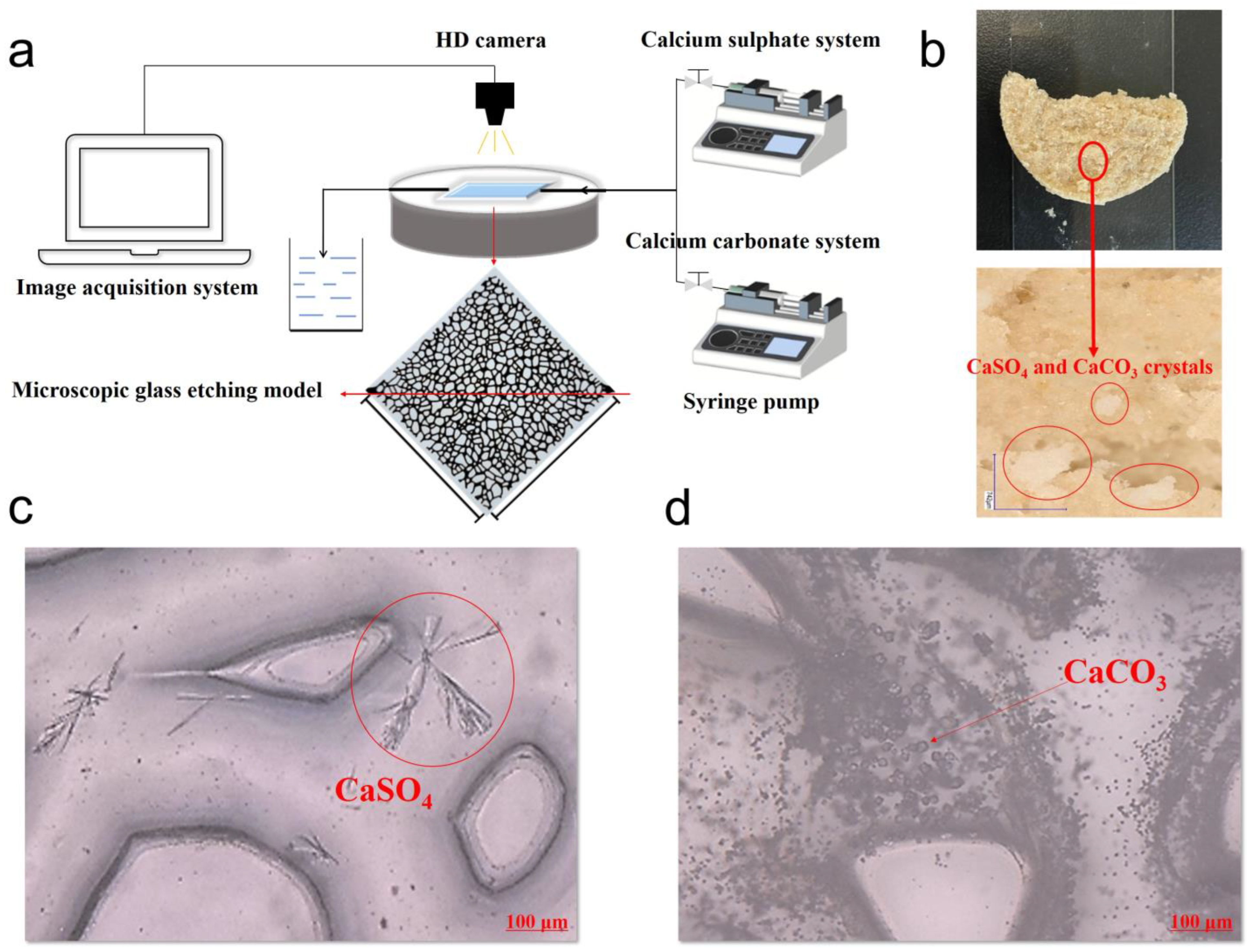
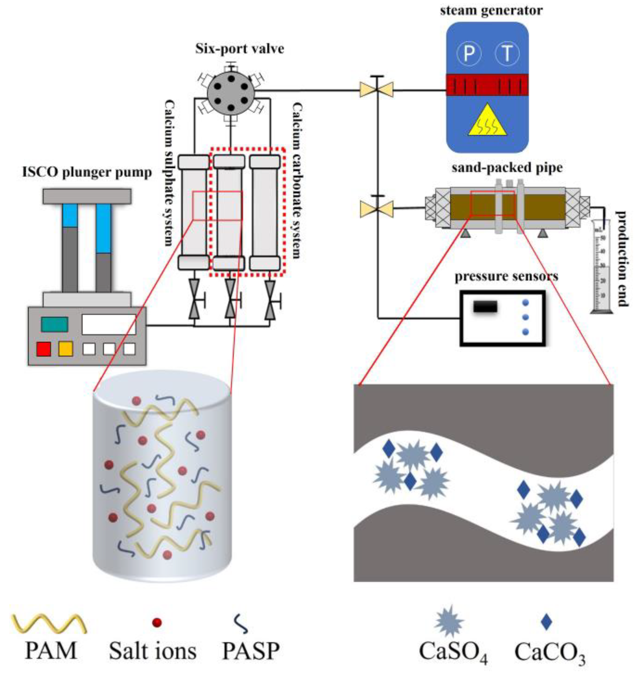
2.4. Micro-Visualization Experiments

The micro-visualization experimental setup consisted of a micro-injection pump, a heterogeneous micro-etched glass model, and a super-depth-of-field microscope. The micro-injection pump and constant-temperature oven provided the necessary flow power and temperature, while the heterogeneous micro-etched glass model simulated the pore structure of the formation; the model’s size was 40 mm × 40 mm. The micro-injection pump injects the plugging agent solution into the pores of the micro-etched glass model, and the super-depth-of-field microscope allows for clear observation of the precipitation of the calcium salt crystals at different locations within the pore structure. We carried out the following steps: Prepare the calcium sulfate blocking agent solution (0.02% PASP + 0.6% PAM + 2% calcium chloride + 2% sodium sulfate) and the calcium carbonate blocking agent solution (1% PAM + 2% sodium carbonate + 2% calcium chloride). Activate the microflow pump and inject the prepared blocking agent solutions into the microscopic glass model sequentially at an injection rate of 0.1 mL·min−1. Use the ultra-depth microscope to record the injection state of the calcium sulfate and calcium carbonate blocking agent solutions. Place the micro-etched glass model filled with the blocking agent solutions in a constant-temperature oven at 100 °C, 200 °C, or 300 °C to heat and precipitate the calcium salt blocking agent solutions. Remove the micro-etched glass model from the thermostat and observe the microscopic morphology of the precipitated crystals and the plugging positions of the precipitates.

2.5. Single-Core Displacement Experiment

In the single-core displacement experiments, an ISCO plunger pump was used to provide the necessary power for injecting the calcium salt plugging agent solutions. A heating jacket and constant-temperature oven were employed to create the precipitation temperature conditions required for the calcium sulfate and calcium carbonate systems. A sand-filled pipe model was used to simulate the formation environment, and a pressure data collector recorded the experimental data. The sand pipe in the single-core model was filled with 80–200-mesh quartz sand. The length of the single-core model was 30 cm, and its diameter was 2.5 cm. The permeability was controlled to 1100 × 10−3 µm2. The water permeability was measured, and the injection flow rate was set at 1 mL·min−1, with the pressure differential P1 recorded on both sides. In the preliminary phase of this study, it was observed that the crystal morphology, precipitation time, and blockage locations within the porous medium varied between the calcium sulfate blocking agent and the calcium carbonate blocking agent. As a result, investigating the impact of different injection ratios for these systems on the performance of the blocked core is essential. Calcium salt blocking agent solutions were prepared, and the injection was carried out using different displacement systems; the injection ratios of calcium sulfate blocking agent to calcium carbonate blocking agent were 0.3 PV + 0.7 PV, 0.4 PV + 0.6 PV, 0.5 PV + 0.5 PV, 0.6 PV + 0.4 PV, and 0.7 PV + 0.3 PV, respectively (single-fluid injection for the calcium sulfate blocking agent and double-fluid injection for the calcium carbonate plugging agent). The blocking agent solutions were injected into the core at a rate of 1 mL·min−1, with the pressure differential P2 recorded. The system was left to stand at 200 °C for 2 days, and high-temperature steam was used to displace the sand-filled pipe model. The stable pressure (P3) and maximum pressure (P4) of the sand-filled pipe model were recorded. The ratios P2/P1, P3/P1, and P4/P1 represent the resistance factor, stable residual resistance factor, and maximum residual resistance factor, respectively.

3. Results

3.1. Screening the Calcium Salt Blocking Agent Systems

3.1.1. Effect of Temperature on the Morphology of Calcium Salt Blocking Agent Systems

In our calcium sulfate blocking agent system, sodium sulfate reacts with calcium chloride to form calcium sulfate precipitate. The addition of PAM and PASP expands the metastable zone of the calcium sulfate, preventing the rapid crystallization of the blocking agent solution. Figure 1a,b show the calcium sulfate blocking agent solution with added PAM and PASP. It can be seen that after standing at room temperature for 24 h, the prepared blocking agent solution remains clear, with no precipitate visible (Figure 1a). PAM, a linear polymer, forms network nodes through entanglement and hydrogen bonds, providing a microgravity environment and isolating crystal nuclei [37]. PASP forms soluble chelates with calcium ions, inhibiting crystal growth [38]. The synergistic effect of these two substances ensures that the calcium sulfate blocking agent solution does not precipitate after 1 d at room temperature. After being heated to 200 °C for 1 d, the viscosity of PAM decreases, reducing its thickening, drag reduction, and dispersion performance. Additionally, the anti-scaling performance of PASP is significantly weakened by heat, resulting in a large amount of precipitate at the bottom of the bottle (Figure 1b). Under a digital microscope, the generated CaSO4 crystals exhibit dispersed tree-like or needle-like structures.
In the calcium carbonate blocking agent system, sodium carbonate reacts with calcium chloride to form calcium carbonate precipitates. PAM is added to the sodium carbonate solution as a high-viscosity single crystalline ion slug, and the calcium chloride solution is used as the subsequent reaction slug. The two solutions mix to form a supersaturated solution, precipitating calcium carbonate crystals. The calcium carbonate blocking agent solution appears turbid at room temperature (Figure 1c) and produces a large amount of precipitate after being heated to 200 °C for 1 d (Figure 1e). The resulting calcium carbonate crystals have a rhombohedral hexagonal structure, characteristic of the calcite form of calcium carbonate, which is its most stable crystal form [39]. The calcium carbonate blocking agent system employs a gel method for crystal growth, with the additives increasing the viscosity of the sodium carbonate solution and providing a microgravity environment, thus inhibiting rapid reactions from occurring when the calcium chloride solution is injected later. The calcium carbonate blocking agent solution with PAM shows an improved plugging performance in the formation at elevated temperatures. The initial viscosities of calcium sulfate and calcium carbonate blocking agents were 16.2 mPa·s and 22.8 mPa·s, respectively, both of which indicate good injectability.

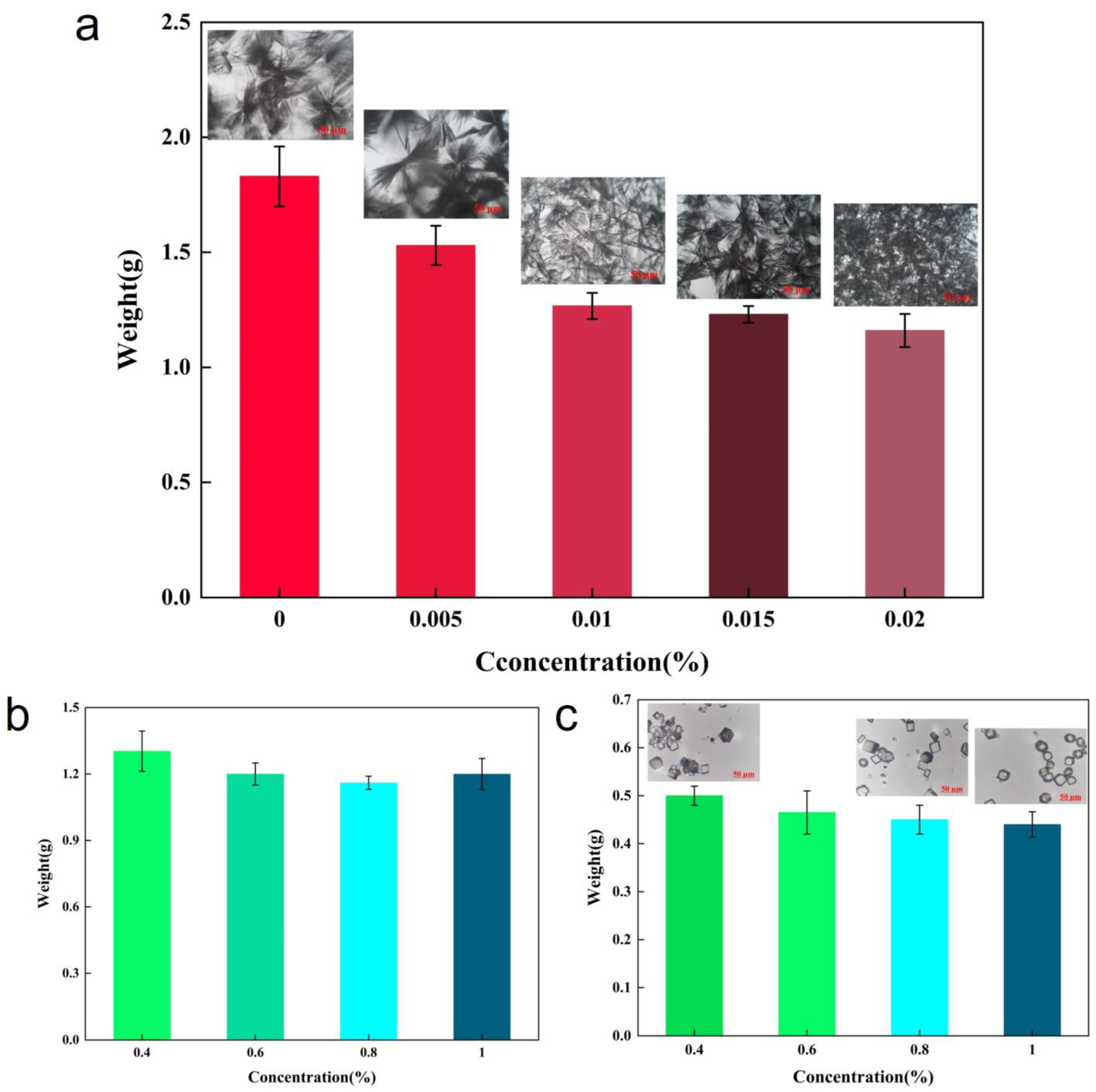
3.1.2. Selection of Suitable Concentrations of PAM and PASP

The scale inhibitor PASP can significantly inhibit the precipitation of calcium sulfate crystals. It demonstrates a notable anti-scaling effect at room temperature, ensuring that the calcium sulfate blocking agent solution can be injected using the single-fluid method without causing initial precipitation that could block the wellbore. However, it still allows crystal precipitation under the formation’s temperature conditions. At the same temperature and over the same length of time, the volume of precipitated crystals in the calcium sulfate blocking agent solution decreases significantly with the increase in the PASP concentration. When the PASP concentration is 0.02%, the dispersant has the most significant inhibitory effect on the calcium sulfate crystals, reducing the amount of crystallization seen after heating the solution to the formation temperature for 1 d by one third (Figure 2a). This indicates that PASP reduces the initial formation of calcium sulfate nuclei, while the size of the precipitated calcium sulfate crystals gradually decreases. The strong chelating effect between the PASP and calcium sulfate crystals inhibits crystal growth. Additionally, PAM (PAM) provides thickening, dispersion, and a microgravity environment, hindering interactions between crystals and resulting in the formation of numerous smaller calcium sulfate crystals. Figure 2b shows the impact of different PAM concentrations on the volume of precipitated crystals in the calcium sulfate blocking agent system when the PASP concentration is fixed at 0.02%. Overall, the PAM concentration has little effect on the volume of the precipitated crystals. The amount of crystallization seen with a high PAM concentration is slightly lower than that with a low PAM concentration. This can be attributed to PAM’s primary role in increasing the solution’s viscosity, granting filtration and isolation dispersion effects to the blocking agent solution. In the calcium carbonate blocking agent system, as shown in Figure 2c, the mass of calcium carbonate crystals does not significantly change with the increase in PAM concentration. Although the amount of calcium carbonate that precipitates is slightly lower with high PAM concentrations, the crystals are more dispersed and aggregation is reduced. Additionally, most of the calcium carbonate crystals exhibit a stable calcite form. The addition of PAM leads to some isolation and nucleation, ensuring crystal dispersion.

3.2. Studies of the Thermal Stability of Calcium Salt Systems

3.2.1. Effect of Temperature on the Precipitation Rate of Calcium Salts

Exploring the thermal stability of calcium salt blocking agent systems is crucial for profile control and water shutoff applications. Figure 3a shows the effect of temperature on the crystallization rate of the proposed calcium sulfate blocking agent system. The addition of PAM and PASP has a significant inhibitory effect on the growth of calcium sulfate crystals, resulting in slow crystal growth. No precipitation occurred within 24 h at room temperature, and crystallization reached a plateau at around 48 h with a crystallization weight of only 0.76 g. As the temperature increased, the crystallization rate significantly accelerated, and the amount of crystallization also increased notably. At 300 °C, a plateau was reached at approximately 12 h, with a crystallized precipitate weight of 2 g, indicating an almost complete precipitation of the blocking agent solution. Figure 3b shows the effect of temperature on the crystallization rate of the calcium carbonate blocking agent system. Overall, the crystallization rate of the calcium carbonate blocking agent system is faster than that of the calcium sulfate system due to the formation of a supersaturated gel solution, which precipitates crystals when the high-viscosity-stage plug and reaction stage come into contact. As shown in Figure 3b, the added PAM initially has a significant inhibitory effect on the growth of the calcium carbonate crystals, resulting in relatively slow crystal growth. At room temperature, nanoscale microcrystals are suspended in the solution when the two plugs first come into contact. After the reaction has been carried out for 12 h, the crystals precipitate to the bottom, with approximately 1 g of precipitated crystals forming after 24 h. As the temperature increases, the crystallization rate and amount of crystallization significantly increase. At 300 °C, a plateau is reached at approximately 12 h, with a crystallized precipitate weight of about 2 g, indicating an almost complete precipitation of the blocking agent solution.

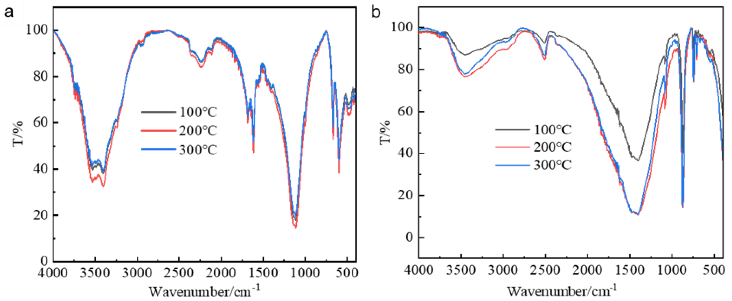
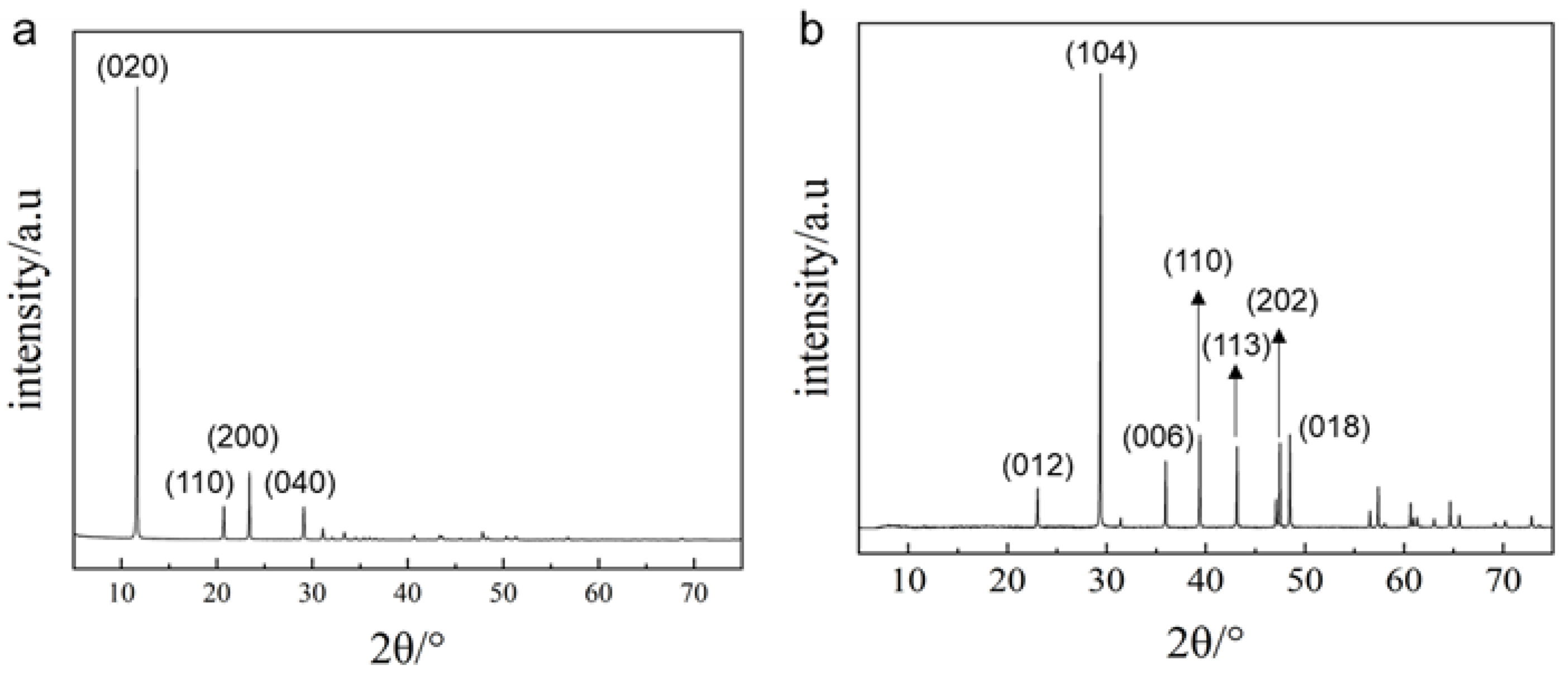
3.2.2. Effect of Temperature on the Crystal Structure of Calcium Salts

Our infrared spectroscopy analysis of the generated crystals (Figure 4) demonstrates that the infrared absorption peaks of calcium salt crystals formed at different temperatures are consistent. In Figure 4a, the peaks at 3560 cm−1, 3660 cm−1, and 1619 cm−1 correspond to water molecules bound to calcium sulfate. The broad bands at 1112 cm−1 and 1152 cm−1 are attributed to the SO42− S-O v3 stretching vibration. The band at 1008 cm−1 corresponds to the SO42− S-O v1 stretching vibration, while the weaker bands at 601 cm−1 and 664 cm−1 correspond to the SO42− S-O bending vibration [40]. These peaks align with the standard infrared spectral characteristics of calcium sulfate, confirming that the generated crystals consist exclusively of calcium sulfate. Figure 4b shows that the generated crystals exhibit distinct peaks at 1418 cm−1, 712 cm−1, and 876 cm−1, respectively, corresponding to the asymmetric stretching and in-plane and out-of-plane bending vibrations of O-C-O, which are characteristic peaks of calcite. Additionally, a weaker peak at 744 cm−1 suggests the presence of both calcite and vaterite crystal forms of calcium carbonate [41]. This indicates that temperature does not affect the inherent properties of the crystals but influences their crystallization quantity and rate.
An XRD analysis was performed on the crystals generated at 200 °C. In Figure 5a, the characteristic peaks of the generated crystals correspond to the (020), (110), (200), and (040) planes, displaying the standard characteristic peaks of calcium sulfate and thereby confirming that the generated crystals are calcium sulfate. In Figure 5b, the XRD peaks correspond to the (012), (104), (006), (110), (113), (202), and (018) planes, confirming that the majority of the generated calcium carbonate crystals are of a calcite crystal form.

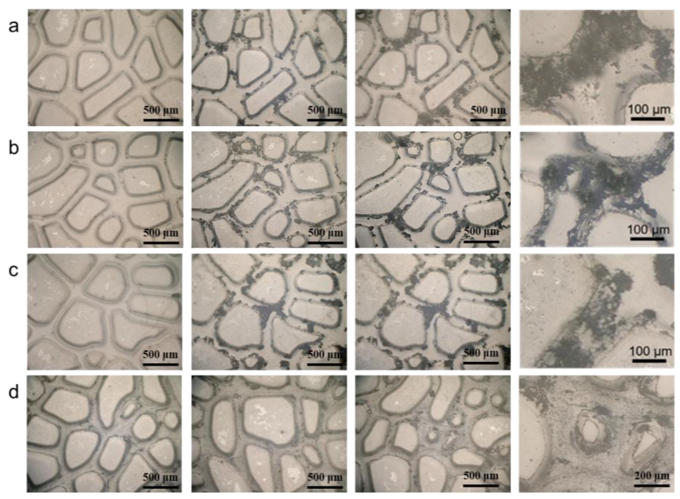
3.3. Analysis of Calcium Salt Crystal Growth in Core Pore Throat

Through microscopic visualization experiments, the plugging position of the precipitated calcium salt blocking agents within pore structures was observed, as well as their plugging patterns under different temperatures and lengths of time. Figure 6a shows the schematic of the experimental setup for microscopic visualization. Figure 6b shows the morphology and distribution of the calcium salt blocking agent systems in the core pore throat. From the comparison between the calcium sulfate blocking agent system and the calcium carbonate blocking agent system, shown in Figure 6c,d, it can be seen that there are differences in the precipitation of the blocking agents within the pores. Firstly, the size of the precipitated crystals varies: the diameter of the precipitated calcium sulfate crystals is significantly larger than that of the precipitated calcium carbonate crystals. Secondly, the location of the precipitated crystals differs: the calcium sulfate blocking agent system produces fewer crystals within a short period of time, with these preferentially precipitating in larger pore channels, while the calcium carbonate blocking agent system produces more crystals, which are uniformly sized and evenly distributed, in a short period of time. These phenomena are attributed to two main factors: the inherent properties of the calcium salt blocking agents and the additives used in each system. PASP is added to control the crystallization rate and prevent rapid nucleation of the calcium sulfate system. In contrast, only PAM is added to the calcium carbonate blocking agent system, allowing the high-viscosity plug to enter the larger pore channels first and then uniformly precipitate crystals. Compared to other solid-phase particle precipitate blockers, these calcium salt blocking agent systems exhibit better injectability and more stable precipitated crystals, providing stronger plugging capabilities. Additionally, their plugging time is controllable, making them suitable for deep profile control and plugging applications.
The precipitation behavior of crystals in the pore structure differs significantly from that in wide-mouthed bottles. Due to the larger specific surface area and rough surface of the pore structure, which provides more nucleation sites, crystals predominantly nucleate heterogeneously in the pore structure, whereas, in wide-mouthed bottles, crystals nucleate predominantly homogeneously. Therefore, it is crucial to investigate the precipitation patterns of precipitated calcium salt plugging agents in pore structures using heterogeneous micro-etched glass models. Temperature significantly influences the precipitation of precipitated calcium salt plugging agents. With the calcium sulfate plugging agent system, at 100 °C, precipitation gradually begins 3 h after injecting the plugging solution, with precipitation crystals observed in the larger pore channels of the micro-pore model after 6 h, and crystals seen growing perpendicular to the rough pore walls by 24 h (Figure 7a). Under the same pore conditions, the calcium sulfate plugging solution exhibits good stability and can effectively precipitate crystals according to the system’s plugging growth patterns, as well as effectively block large pore channels, following the theory of preference for growth at rough interfaces, as the mechanism of crystal growth seen preferentially blocks throats with minimal crystallization. At 200 °C and after 12 h, more and larger precipitation crystals are observed in the plugging solution, enhancing the sealing effect. With increasing time—after 24 h—larger crystal sizes and a greater numbers of crystals are observed, resulting in a better sealing effect which is conducive to subsequent steam injection into low-permeability reservoirs affected by mobility differences (Figure 7b). At 300 °C, precipitation gradually begins 2 h after injecting the plugging solution, with crystals starting to aggregate and grow in the larger pore channels of the micro-pore model after 12 h (Figure 7c). At 300 °C, the plugging solution shows a faster crystallization rate, with more and larger precipitation crystals appearing, significantly blocking the large pore channels and transforming the pore structure from highly porous and highly permeable to moderately porous and less heterogeneous. The calcium sulfate plugging solution also demonstrates good stability at 300 °C, indicating the excellent thermal resistance of these calcium salt plugging agents, which effectively block large pore channels according to the theory of crystal growth at rough interfaces and due to the mechanism of crystal growth preferentially blocking throats with minimal crystallization. As the temperature increases, the oversaturation of the calcium sulfate plugging system increases, accelerating crystal growth and enhancing plugging speed.
The precipitation of calcium sulfate crystals within the plugging agent system selectively blocks large pore channels for two primary reasons. Firstly, the roughness of the solid surface contacted by the solution affects nucleation: rougher surfaces accelerate nucleation accumulation, thus speeding up crystallization rates. Conversely, slower nucleation accumulation rates lead to slower crystallization rates and smaller amounts of precipitation. Crystal growth in reservoir pore spaces resembles the growth at rough interfaces, where all positions on the interface contribute to growth, requiring neither two-dimensional nucleation nor misfit dislocation sites, with adsorbed atoms randomly entering lattice sites to facilitate crystal growth [42]. Secondly, under constant oversaturation conditions, the fluid flow rate affects the growth mechanism of the plugging agent system. In the throats of large pore channels, where the fluid seepage velocity is higher, the crystal growth rate is faster, making it easier to block throats with growing crystals [43]. The mechanism that enables the preferential blocking of throats with growing crystals is the main mechanism used for efficiently sealing large pore channels and the reason why minimal crystallization achieves efficient sealing.
Calcium carbonate crystallizes quickly. Figure 7d shows the microscopic visualization of the crystallization experiments conducted on calcium carbonate plugging systems at different temperatures. The calcium carbonate plugging systems were alternately injected into microscopic glass models and left to stand at 100 °C for 6 h. A uniform distribution of calcium carbonate precipitation crystals was observed in the pore channels of the microscopic pore model. As the temperature increased to 200 °C, and even 300 °C, calcium carbonate precipitation crystals were observed to begin aggregating and growing in the larger pore channels of the microscopic pore model, albeit with smaller crystal dimensions compared to those of the calcium sulfate plugging agent system, indicating a weaker improvement in heterogeneity performance.

3.4. Analysis of the Plugging Performance of Calcium Salt Blocking Agent Systems

Figure 8 shows a schematic diagram of the equipment used in the plugging test. In the single-core displacement experiments, during the injection of two different plugging agent solutions at varying ratios, the pressure differential change followed a similar trend no matter the ratio. As shown in Figure 9, during the injection of the blocking agents, the pressure continuously increased and retained an upward trend. In the steam flooding process, the pressure differential initially increased, reaching a peak, then decreased, and finally stabilized during the displacement phase. During the steam injection, high-pressure steam drove the plugging system deeper into the formation, while high temperatures promoted the growth of precipitated crystals in the deeper layers. The reason for the subsequent decrease in and stabilization of the pressure during steam flooding is that part of the steam pushes the plugging system further into the formation, while the remaining portion continues to block the flow.
Table 1 presents a comparison of the resistance factors of five different injection agent ratios. When the injection agent ratio was 0.3 PV + 0.7 PV, the maximum residual resistance factor was 45.95, with the highest pressure during displacement reaching 1.1 MPa. During steam flooding, the pressure suddenly dropped for a period, resulting in a stable residual resistance factor of only 40.00. This indicated a weaker plugging ability and an unstable resistance to erosion. For the injection agent ratio of 0.4 PV + 0.6 PV, the maximum residual resistance factor was 278.00 and, during subsequent steam injection, the pressure decreased only slightly, with the stable residual plugging factor reaching 244.50. When the injection agent ratio was 0.5 PV + 0.5 PV, the maximum residual resistance factor was 256.92, and the pressure breakthrough during displacement was also high. Although there was a slight decrease in pressure during steam flooding, the drop was minimal. In conclusion, the injection agent ratios of 0.4 PV + 0.6 PV and 0.5 PV + 0.5 PV demonstrated better plugging capabilities compared to other injection ratios.
As also shown in Tang’s research [44,45], the addition of inhibitors to the calcium salt precipitation system temporarily prevents calcium salt precipitation at room temperature and results in less precipitation over the same period at high temperatures. Even when a highly concentrated system enters the formation through the wellbore, it will not block the wellbore or the near-well zone. Instead, it can be transported to deeper parts of the formation, facilitating a deep profile and ensuring an optimal injection performance and sealing capability.

4. Conclusions

This study investigates the crystal growth patterns and blocking mechanisms of high-temperature-resistant precipitated calcium salt blocking agents in porous media. Calcium sulfate plugging agents precipitate more significantly with increasing temperature, making them suitable for single-fluid injection. Conversely, calcium carbonate plugging agents crystallize rapidly and require dual-fluid injection. Both calcium salt blocking agents facilitate crystal growth within pores, leading to severe pore blockage. Their crystal growth exhibits the characteristics of perpendicular growth, aligning with theories on rough-interface crystal growth. Larger normal growth spaces facilitate crystal enlargement, provided there is a continuous supply of crystal growth solution to fill the growth space. High-temperature-resistant precipitated calcium salt plugging agents not only plug effectively but essentially remodel reservoir pore structures, transforming high-porosity, high-permeability reservoirs into moderate-porosity, moderate-permeability ones, thereby reducing reservoir heterogeneity. In oil field applications, two calcium salt plugging agents are used, and the concentrations of their dispersants are adjusted to achieve system blockage at specific times and locations, thereby synergistically regulating unbalanced vapor seepage in heavy oil reservoirs.

Author Contributions

Methodology, G.S., Y.J. and Q.C.; Formal analysis, Z.S. and N.K.; Investigation, G.S., Z.S., N.K. and Y.J.; Data curation, Z.S., N.K., Q.C. and X.W.; Writing—original draft, Z.S.; Writing—review and editing, Q.C.; Supervision, Y.J.; Project administration, G.S. All authors have read and agreed to the published version of the manuscript.

Funding

This research has been funded by the National Natural Science Foundation of China under Grant Number U22B20144.

Data Availability Statement

The original contributions presented in this study are included in the article. Further inquiries can be directed to the corresponding author.

Acknowledgments

We are grateful to the Shandong Engineering Research Center for CO2 Utilization and Storage for their kind help with this study. The valuable comments made by the anonymous reviewers are also sincerely appreciated.

Conflicts of Interest

Authors Guolin Shao and Yunfei Jia were employed by the Sinopec Shengli Oilfield Company of the China Petroleum and Chemical Corporation. The remaining authors declare that the research was conducted in the absence of any commercial or financial relationships that could be construed as a potential conflict of interest. The Sinopec Shengli Oilfield Company of the China Petroleum and Chemical Corporation had no role in the design of this study; in the collection, analyses, or interpretation of data; in the writing of the manuscript, or in the decision to publish the results.

References

  1. Tomaszewski, R. A comparative study of citations to chemical encyclopedias in scholarly articles: Kirk-Othmer Encyclopedia of Chemical Technology and Ullmann’s Encyclopedia of Industrial Chemistry. Scientometrics 2018, 117, 175–189. [Google Scholar] [CrossRef]
  2. Dou, L.R.; Li, D.W.; Wen, Z.X.; Wang, Z.M.; Mi, S.Y.; Zhang, Q. History and outlook of global oil and gas resources evaluation. Acta Pet. Sin. 2022, 43, 1035–1048. [Google Scholar]
  3. Jia, C.Z.; Pang, X.Q.; Song, Y. The mechanism of unconventional hydrocarbon formation: Hydrocarbon self-containment and intermolecular forces. Pet. Explor. Dev. 2021, 48, 437–452. [Google Scholar] [CrossRef]
  4. Xue, L.; Liu, P.C.; Zhang, Y. Development and research status of heavy oil enhanced oil recovery. Geofluids 2022, 1, 5015045. [Google Scholar] [CrossRef]
  5. Xiong, R.Y.; Guo, J.X.; Kiyingi, W.; Gao, C.H.; Wang, L.; Luo, J.J.; Song, H.X.; Wang, X.W. Technical transformation of heavy/ultra-heavy oil production in China driven by low carbon goals: A review. J. Clean. Prod. 2024, 458, 142531. [Google Scholar] [CrossRef]
  6. Guo, K.; Li, H.L.; Yu, Z.X. In-situ heavy and extra-heavy oil recovery: A review. Fuel 2016, 185, 886–902. [Google Scholar] [CrossRef]
  7. Malozyomov, B.V.; Martyushev, N.V.; Kukartsev, V.V.; Tynchenko, V.S.; Bukhtoyarov, V.V.; Wu, X.G.; Tyncheko, Y.A.; Kukartsev, V.A. Overview of Methods for Enhanced Oil Recovery from Conventional and Unconventional Reservoirs. Energies 2023, 16, 4907. [Google Scholar] [CrossRef]
  8. Pan, Y.; Qiao, W.; Chi, D.X.; Li, Z.X.; Shu, Y.J. Research of steam injection in-situ production technology to enhance unconventional oil and gas recovery: A review. J. Anal. Appl. Pyrolysis 2024, 177, 106332. [Google Scholar] [CrossRef]
  9. Qiao, J.; Zeng, J.; Jiang, S.; Feng, S.; Feng, X.; Guo, Z.; Teng, J. Heterogeneity of reservoir quality and gas accumulation in tight sandstone reservoirs revealed by pore structure characterization and physical simulation. Fuel 2019, 253, 1300–1316. [Google Scholar] [CrossRef]
  10. Dianshi, X.; Shuangfang, L.; Jinxiu, Y.; Luchuan, Z.; Bo, L. Classifying Multiscale Pores and Investigating Their Relationship with Porosity and Permeability in Tight Sandstone Gas Reservoirs. Energy Fuels 2017, 31, 9188–9200. [Google Scholar]
  11. Yuan, B.; Wood, D.A. A comprehensive review of formation damage during enhanced oil recovery. J. Pet. Sci. Eng. 2018, 167, 287–299. [Google Scholar] [CrossRef]
  12. Zhao, P.C.; Zhao, H.T.; Bai, B.J.; Yang, X.M. Improve injection profile by combining plugging agent treatment and acid stimulation. SPE Improv. Oil Recovery Conf. 2004, SPE-89394-MS. [Google Scholar]
  13. Gomaa, S.; Salem, K.G.; El-hoshoudy, A.N. Enhanced heavy and extra heavy oil recovery: Current status and new trends. Petroleum 2024, 3, 399–410. [Google Scholar] [CrossRef]
  14. Alvarez, J.; Han, S. Current overview of cyclic steam injection process. J. Pet. Sci. Res. 2023, 2, 116–127. [Google Scholar]
  15. Zhao, G.; Dai, C.L.; Gu, C.L.; You, Q.; Sun, Y.P. Expandable graphite particles as a novel in-depth steam channeling control agent in heavy oil reservoirs. Chem. Eng. J. 2019, 368, 668–677. [Google Scholar] [CrossRef]
  16. Li, B.L.; Li, B.F.; Zang, Y.N.; Zhu, D.; Li, Z.M.; Ruan, L.W. Experimental study of the distillation mechanism during co-injection of flue gas and steam for heavy oil development. Sep. Purif. Technol. 2023, 324, 124553. [Google Scholar] [CrossRef]
  17. Liu, P.; Shi, L.; Liu, P.; Li, L.; Hua, D. Experimental study of high-temperature CO2 foam flooding after hot-water injection in developing heavy oil reservoirs. J. Pet. Sci. Eng. 2020, 185, 106597. [Google Scholar] [CrossRef]
  18. Zhu, D.; Li, B.F.; Chen, L.K.; Zhang, C.B.; Zheng, L.; Chen, W.Q.; Li, Z.M. Experimental investigation of CO2 foam flooding-enhanced oil recovery in fractured low-permeability reservoirs: Core-scale to pore-scale. Fuel 2024, 362, 130792. [Google Scholar] [CrossRef]
  19. Li, S.P.; Yao, Z.Y.; Shang, F.H.; Li, M.H.; Wei, Y.H.; Li, S.Y. Improving CO2 storage efficiency in saline aquifers through wettability-optimized nanoparticle foam. Phys. Fluids 2025, 37, 013351. [Google Scholar] [CrossRef]
  20. Islam, M.; Ali, S.F. Use of silica gel for improving waterflooding performance of bottom-water reservoirs. J. Pet. Sci. Eng. 1993, 8, 303–313. [Google Scholar] [CrossRef]
  21. Xu, L. Chemical water shutoff profile research status and development trends. IOP Conf. Ser. Earth Environ. Sci. 2017, 82, 012061. [Google Scholar] [CrossRef]
  22. Liu, J.; Zhong, L.; Wang, C.; Li, S.; Yuan, X.; Liu, Y.; Meng, X.; Zou, J.; Wang, Q. Investigation of a high temperature gel system for application in saline oil and gas reservoirs for profile modification. J. Pet. Sci. Eng. 2020, 195, 107852. [Google Scholar] [CrossRef]
  23. Wang, B.; Lin, M.; Guo, J.; Wang, D.; Xu, F.; Li, M. Plugging properties and profile control effects of crosslinked polyacrylamide microspheres. J. Appl. Polym. Sci. 2016, 133. [Google Scholar] [CrossRef]
  24. Xie, K.; Su, C.; Liu, C.L.; Cao, W.J.; He, X.; Ding, H.N.; Mei, J.; Yan, K.; Cheng, Q.; Lu, X.G. Synthesis and Performance Evaluation of an Organic/Inorganic Composite Gel Plugging System for Offshore Oilfields. Acs Omega 2022, 7, 12870–12878. [Google Scholar] [CrossRef] [PubMed]
  25. Jaripatke, O.; Dalrymple, D. Water-control management technologies: A review of successful chemical technologies in the last two decades. SPE Int. Conf. Exhib. Form. Damage Control 2010, SPE-127806-MS. [Google Scholar] [CrossRef]
  26. Caili, D.; Qing, Y.; Fulin, Z. In-depth profile control technologies in China—A review of the state of the art. Pet. Sci. Technol. 2010, 28, 1307–1315. [Google Scholar] [CrossRef]
  27. Zhai, K.; Yi, H.; Liu, Y.; Geng, Y.; Fan, S.; Zhu, D. Experimental evaluation of the shielded temporary plugging system composed of calcium carbonate and acid-soluble preformed particle gels (ASPPG) for petroleum drilling. Energy Fuels 2020, 34, 14023–14033. [Google Scholar] [CrossRef]
  28. Cui, G.; Ren, S.; Dou, B.; Ning, F. Geothermal energy exploitation from depleted high-temperature gas reservoirs by recycling CO2: The superiority and existing problems. Geosci. Front. 2021, 12, 101078. [Google Scholar] [CrossRef]
  29. Barbosa, M.V.; Teixeira, L.A.C.; Martins, A.R.F.D.; Santos, B.F.D. Process Optimization for the Production of Ferric Sulfate Coagulant by the Oxidation of Ferrous sulfate with Hydrogen Peroxide. Chem. Prod. Process Model. 2020, 15, 20190091. [Google Scholar] [CrossRef]
  30. Erofeev, V.I.; Xiangguo, L. Optimization of parameters of inorganic profile control agent on the basis of sodium silicate for effective oil displacement from high salinity reservoir. Тoмскoгo Пoлитехническoгo Университета Инжиниринг Геoресурсoв 2019, 54, 67. [Google Scholar]
  31. Acock, A.M.; Reis, J.C. Oil recovery improvement through profile modification by thermal precipitation. SPE Improv. Oil Recovery Conf. 1994, SPE-27831-MS. [Google Scholar]
  32. Zhu, T.; Tiab, D. Improved sweep efficiency by selective plugging of highly watered out zones by alcohol induced precipitation. J. Can. Pet. Technol. 1993, 32, PETSOC-93-09-05. [Google Scholar] [CrossRef] [PubMed]
  33. Hashemi, S.J.; Hormozi, F.; Mokhtari, R. Controlling the gelation time of sodium silicate gelants for fluid management in hydrocarbon reservoirs. Fuel 2023, 341, 127645. [Google Scholar] [CrossRef]
  34. Trukhina, M.; Tkachenko, S.; Ryabova, A.; Oshchepkov, M.; Redchuk, A.; Popov, K. Calcium sulfate crystallization in presence of fluorecent-tagged polyacrylate and some refinement of scale inhibition mechanism. Minerals 2023, 13, 559. [Google Scholar] [CrossRef]
  35. Cheng, Q.; Li, B.F.; Shi, Z.; Shao, G.L.; Li, B.L.; Kang, N.; Wang, X.Q. Preparation and plugging characteristics investigation of a high temperature induced calcium salt precipitation system for profile control in high temperature reservoirs. Colloids Surf. A: Physicochem. Eng. Asp. 2025, 711, 136413. [Google Scholar] [CrossRef]
  36. Zhu, G.; Li, H.; Li, S.; Hou, X.; Xu, D.; Lin, R.; Tang, Q. Crystallization behavior and kinetics of calcium carbonate in highly alkaline and supersaturated system. J. Cryst. Growth 2015, 428, 16–23. [Google Scholar] [CrossRef]
  37. Liu, Y.; Xian, W.; He, J.; Li, Y. Interplay between entanglement and crosslinking in determining mechanical behaviors of polymer networks. Int. J. Smart Nano Mater. 2023, 14, 474–495. [Google Scholar] [CrossRef]
  38. Adelnia, H.; Sirous, F.; Blakey, I.; Ta, H.T. Metal ion chelation of poly (aspartic acid): From scale inhibition to therapeutic potentials. Int. J. Biol. Macromol. 2023, 229, 974–993. [Google Scholar] [CrossRef]
  39. Zhong, M.; Liu, B.; Chen, J.; Yan, G. Research on plugging characteristics of microorganism induced calcite precipitation in sandstone environment. J. Pet. Sci. Eng. 2022, 218, 111040. [Google Scholar] [CrossRef]
  40. Morris, R. Infrared spectrophotometric analysis of calcium sulfate hydrates using internally standardized mineral oil mulls. Anal. Chem. 1963, 35, 1489–1492. [Google Scholar] [CrossRef]
  41. Vagenas, N.V.; Gatsouli, A.; Kontoyannis, C.G. Quantitative analysis of synthetic calcium carbonate polymorphs using FT-IR spectroscopy. Talanta 2003, 59, 831–836. [Google Scholar] [CrossRef] [PubMed]
  42. Garside, J.; Mersmann, A.; Nývlt, J. Measurement of Crystal Growth and Nucleation Rates; IChemE: Birmingham, UK, 2002. [Google Scholar]
  43. Moghadasi, J.; Jamialahmadi, M.; Müller-Steinhagen, H.; Sharif, A. Scale formation in oil reservoir and production equipment during water injection kinetics of CaSO4 and CaCO3 crystal growth and effect on formation damage. SPE Eur. Form. Damage Conf. Exhib. 2003, SPE-82233-MS. [Google Scholar]
  44. Tang, X.F.; Shao, L.M.; Tan, H.; Liu, S.J.; Niu, L.W.; Ye, Y.Z. Improvement of Water Flooding Efficiency by Using the Reservoir Forming Ion Source to Realize the Adjustment of the Dominant Channel. Oilfield Chem. 2018, 35, 257–262. [Google Scholar]
  45. Niu, L.W.; Lu, X.G.; Xiong, C.M.; Tang, X.F.; Wu, X.C.; Jia, X.; Zhang, S. Experimental study on gelling property and plugging effect of inorganic gel system (OMGL). Pet. Explor. Dev. 2013, 40, 728–732. [Google Scholar] [CrossRef]
Figure 1. The crystallization process of the calcium salt blocking agents. Calcium sulfate blocking agent kept at 25 °C for 1 d (a) and 200 °C for 1 d (b); calcium carbonate blocking agent kept at 25 °C for 1 d (d) and 200 °C for 1 d (e); crystal morphology of generated CaSO4 (c) and CaCO3 (f).
Processes 13 01319 g001
Figure 2. (a) Precipitation mass and morphology of calcium sulfate with different concentrations of PASP; (b) precipitation mass of calcium sulfate with different concentrations of PAM; (c) precipitation mass and morphology of calcium carbonate with different concentrations of PAM.
Processes 13 01319 g002
Figure 3. The influence of temperature on the crystallization rate: calcium sulfate (a), calcium carbonate (b).
Processes 13 01319 g003
Figure 4. Infrared spectrum of calcium sulfate (a) and carbonate crystals (b).
Processes 13 01319 g004
Figure 5. X-ray diffraction of calcium sulfate (a) and carbonate crystals (b).
Processes 13 01319 g005
Figure 6. (a) Microscopic visualization device used for assessing calcium salt plugging agents. (b) The morphology and distribution of the calcium salt blocking agent systems in the core pore throat. Comparison between calcium sulfate blocking agent (c) and calcium carbonate blocking agent (d).
Processes 13 01319 g006
Figure 7. The pore growth characteristics of CaSO4 and CaCO3 plugging agents. Calcium sulfate plugging agent tested at 100 °C (a), 200 °C (b), and 300 °C (c) for 3 h, 12 h, and 24 h. Heating of calcium carbonate plugging agent tested at 100 °C, 200 °C, and 300 °C for 6 h (d).
Processes 13 01319 g007
Figure 8. Schematic diagram of the equipment used in the plugging test. The intermediate vessel contains calcium sulfate and calcium carbonate systems, consisting of salt ions, PASP, and PAM. The calcium salt system slowly generates CaSO4 and CaCO3 crystals in the core under high-temperature conditions.
Processes 13 01319 g008
Figure 9. Change in displacement pressure difference with different injection ratios (af).
Processes 13 01319 g009
Table 1. Experimental results of calcium salt plugging agents at different injection ratios.
Injection Agent Ratio/PVResistance FactorMaximum Residual Resistance FactorStable Residual Resistance FactorPlugging Rate/%
0.3 + 0.748.0045.9540.0097.50
0.4 + 0.655.13278.00244.5099.59
0.5 + 0.552.10256.92212.8299.53
0.6 + 0.451.79160.53101.0599.01
0.7 + 0.349.7279.4671.3598.00
Disclaimer/Publisher’s Note: The statements, opinions and data contained in all publications are solely those of the individual author(s) and contributor(s) and not of MDPI and/or the editor(s). MDPI and/or the editor(s) disclaim responsibility for any injury to people or property resulting from any ideas, methods, instructions or products referred to in the content.

