1. Introduction
Diesel power generation cabins serve as autonomous energy support systems, capable of supplying power to outdoor equipment in remote or off-grid environments. They hold significant value and are widely utilized across diverse sectors, including telecommunications [
1], scientific research stations [
2,
3,
4], mining [
5], and emergency disaster relief efforts [
6]. These systems provide reliable power in extreme and isolated conditions, ensuring the continuous operation of critical infrastructure and equipment in a range of industries. However, in some cold regions (such as Antarctica and plateaus), the extremely low-temperature environment causes thermal imbalance problems inside the cabins. When a cabin operates in a low-temperature external environment, the bottom of the cabins becomes cold, which increases the fuel viscosity in the tank and makes it difficult to start the generator. In extreme environments (outdoor temperature below −60 °C), if the temperature at the bottom of the tank inside the cabin drops below −40 °C and freezes the fuel, then the diesel engines will stop irreversibly [
7]. Another significant problem arises from the engine block, a high heat source. The diesel engine operates with an efficiency of about 33%, losing 30% of its energy through exhaust gas and 37% through cooling air and radiation [
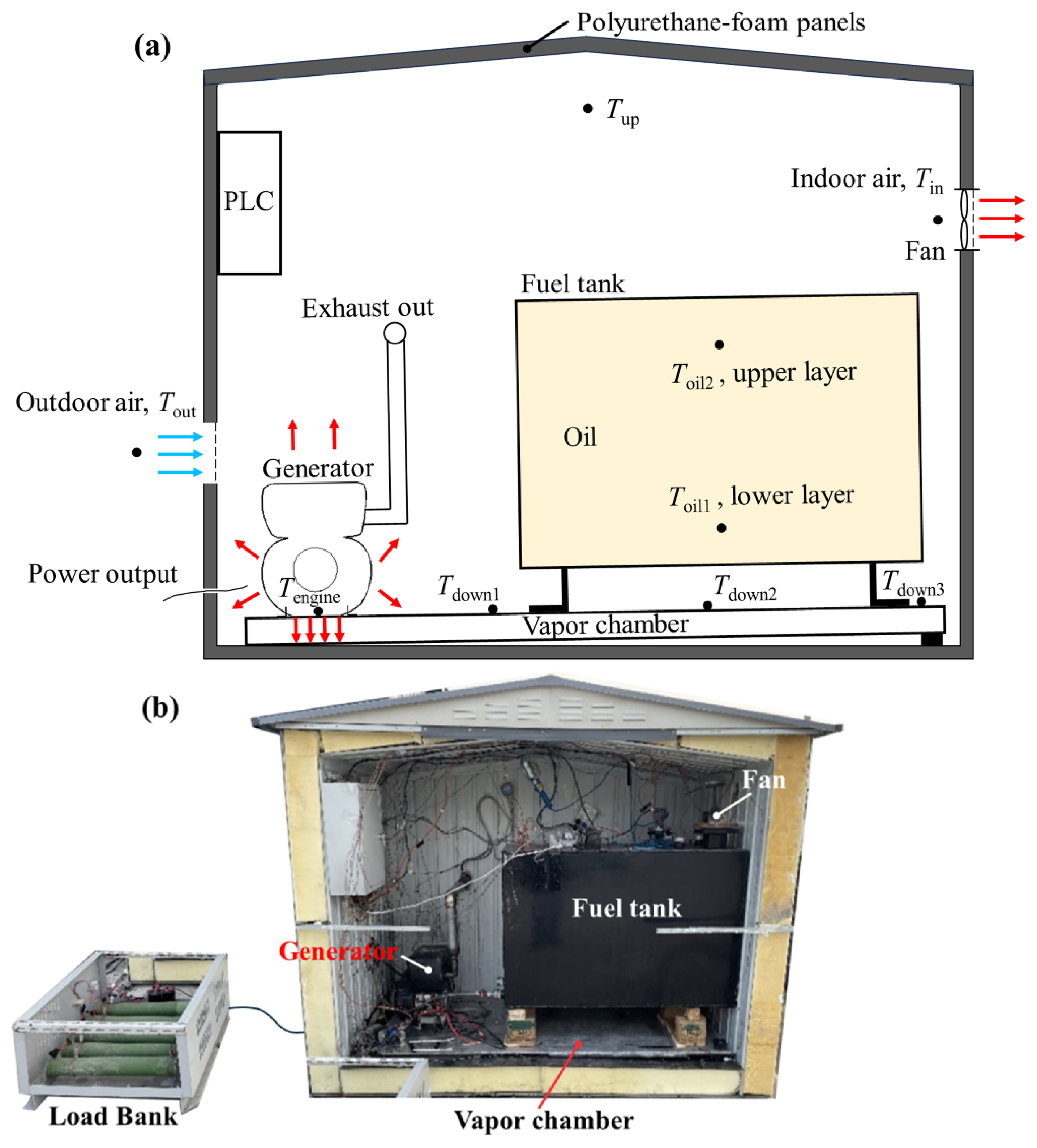
8]. In practice, a large part of the exhaust heat is coupled to the engine block through radiation and heat transfer. Therefore, even when the outdoor temperature is below −20 °C, the engine block temperature during operation still exceeds 60 °C, and the air temperature near the exhaust pipe exceeds 120 °C. This results in a large temperature difference between the upper and lower cabin air. When part of the indoor air temperature exceeds 60 °C, it will reduce the service life of other electrical equipment in the cabin (e.g., PLC) or even damage it directly. In summary, reasonable heat management in power generation cabins is an urgent problem that needs to be solved.
To address this issue, Lawrence et al. [
9] secured all engines to the top of the fuel tank with thick aluminum sheets, which helped to conduct heat from the engine to the bottom of the tank and keep the fuel liquid. Moreover, they ran the fuel pumps on all non-running engines continuously to circulate the fuel in a warm environment from the bottom of the tank to the bottom of the engine. However, this method had some drawbacks. First, the thermal conductivity of the aluminum sheet was limited, so only a small amount of engine heat could be utilized. Second, running the fuel pump for long periods increased energy consumption and risked damaging the fuel pump. Therefore, there is a need for passive heat transfer devices with better thermal conductivity to enhance the utilization of diesel engine heat and ensure the long-term and reliable operation of the power generation cabin. Deng et al. [
10] constructed a scaled-down model of the power generation cabin to simulate its annual dynamic temperature characteristics and thermal behavior under seasonal temperature variations in Antarctica. They presented the annual dynamic changes in indoor air and oil temperatures and analyzed the effects of ventilation rate and intermittent operation on indoor air temperature. The results suggested that the power generation cabin should be equipped with air inlets and exhaust fans to control the indoor air temperature. However, their experiments were limited to the scaled-down model and an unsteady model based on the lumped-parameter method, without extending to actual cabin-scale experiments. After a comprehensive review of the current research status of the operation of power generation cabins in a cold environment, it is found that there are two major problems: Firstly, the temperature uniformity inside the cabin is poor; secondly, due to the influence of the low-outdoor-temperature environment, there is a risk of the fuel freezing. The current solutions are limited by the inherent thermal conductivity of metal materials, making it difficult to fully utilize the heat generated during the operation of the generator. If it is possible to find a way to improve the heat transfer efficiency between the generator and the fuel tank, skillfully use the heat generated during the operation of the generator to increase the fuel temperature, and simultaneously heat the bottom air, then not only can the temperature uniformity inside the cabin be significantly improved, but also the potential risk of fuel freezing can be effectively avoided.
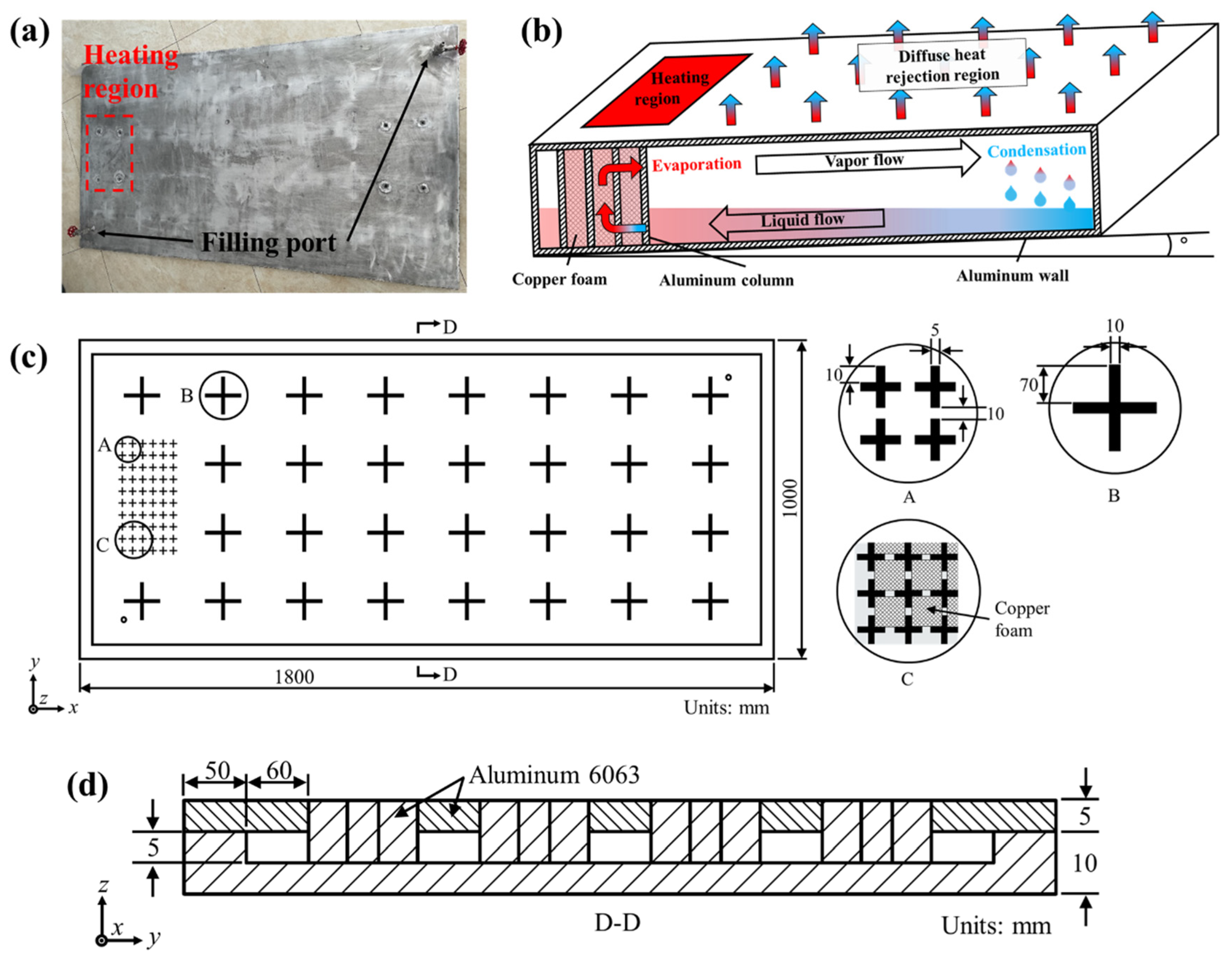
The vapor chamber (VC) is a kind of phase-change heat transfer element for two-dimensional plane heat dissipation. It relies on the phase-change heat transfer of the internal working fluid [
11,
12,
13] to rapidly transfer the heat from the high-temperature area to the condensing end with a larger heat dissipation area. As an efficient and reliable passive heat transfer element, it has been widely applied in various fields such as electronic devices [
14,
15,
16], architecture [
17,
18], aerospace [
19,
20,
21], and the military [
22]. Currently, the research related to VCs mainly centers around structural optimization [
23] and the selection of working fluids [
24] to enhance the heat transfer efficiency. Compared with traditional metal heat transfer devices, vapor chambers generally possess higher heat transfer performance. Chen et al. [
25] experimentally investigated the heat transfer performance of ultra-thin vapor chambers. They found that the effective thermal conductivity of the ultra-thin vapor chamber reached 12,000 W∙m
−1∙K
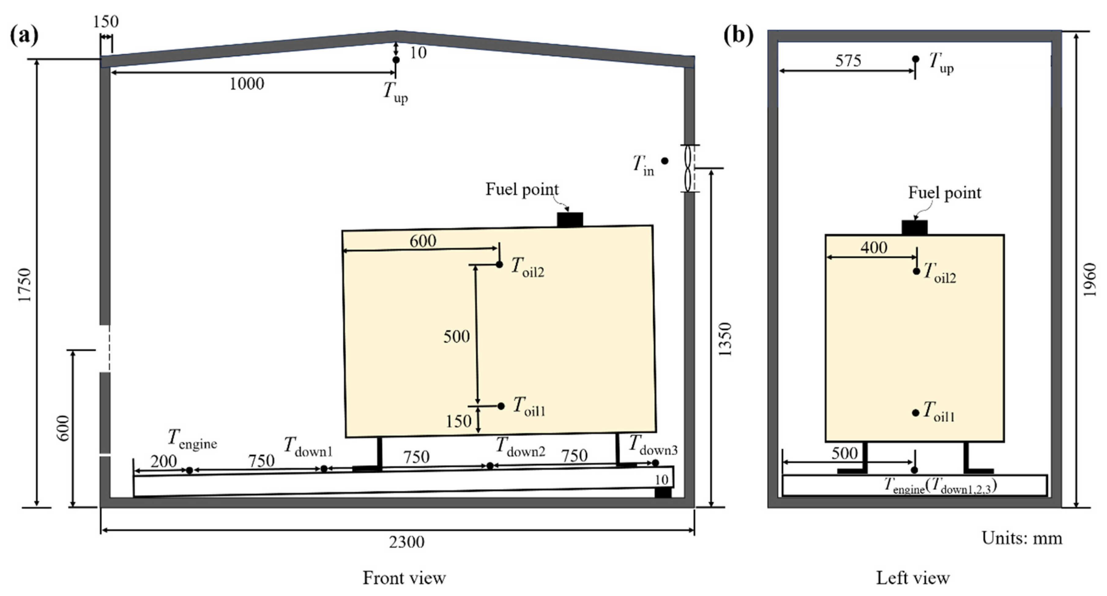
−1, which is 30 times that of pure copper. In addition, the ultra-thin vapor chamber had better temperature uniformity and thermal response performance. As previously stated, the operation of power generation cabins in a cold environment faces the technical challenge of thermal imbalance. The vapor chamber can make better use of the heat generated by the diesel engine itself and spontaneously regulate the temperature uniformity of the power generation cabin and the fuel. In this study, we designed and constructed a low-temperature power generation platform for operation in environments where outdoor temperatures fall below −20 °C. A transverse heat transfer VC was integrated at the base of the cabin, with the evaporative section positioned beneath the diesel engine and the condensing section located beneath the fuel tank. This configuration facilitates efficient heat transfer from the diesel engine’s base to the fuel tank’s bottom, thereby insulating the floor from extremely low temperatures and raising the fuel temperature to prevent freezing at critical points. Additionally, an exhaust fan was employed to actively expel warm air, reducing the air temperature near the cabin roof. This method ensures that electrical equipment operates in a thermally suitable environment.
3. Results and Discussion
3.1. Effect of Natural and Forced Convection on Cabin Temperature
All the experiments in this section were conducted without the installation of the VC. The ventilation volume is essential data for designing the power generation cabin. Here, we discuss the effects of natural convection and forced convection on the temperature inside the cabin. During natural convection, there is no fan at the air outlet, and the air inside the cabin is drawn in only by the diesel generator’s natural aspiration. In the case of forced convection, the air is expelled through the exhaust fan to accelerate air circulation inside the cabin. The entire experiment was conducted outdoors, with an outdoor temperature of −20 °C.
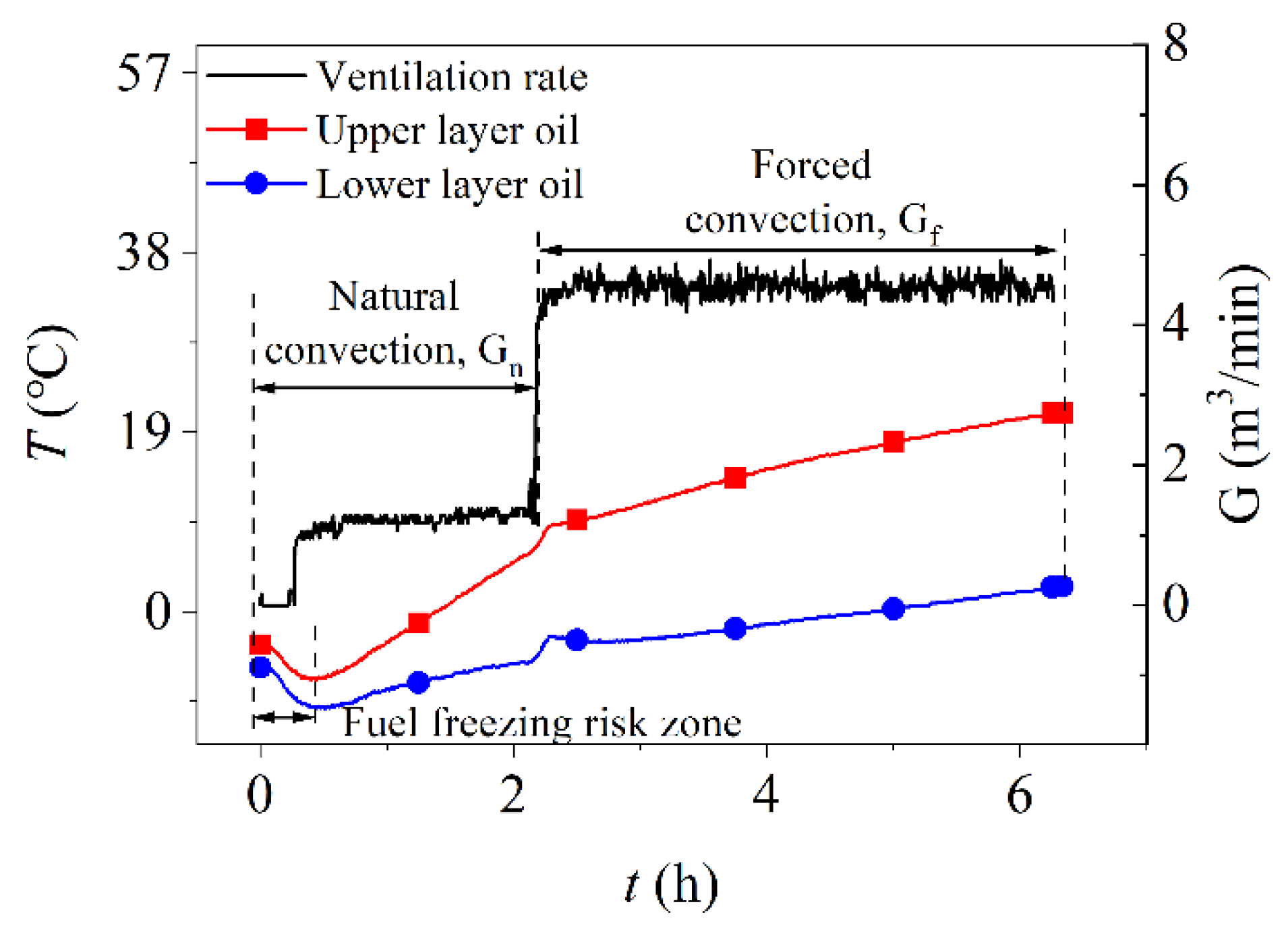
As shown in
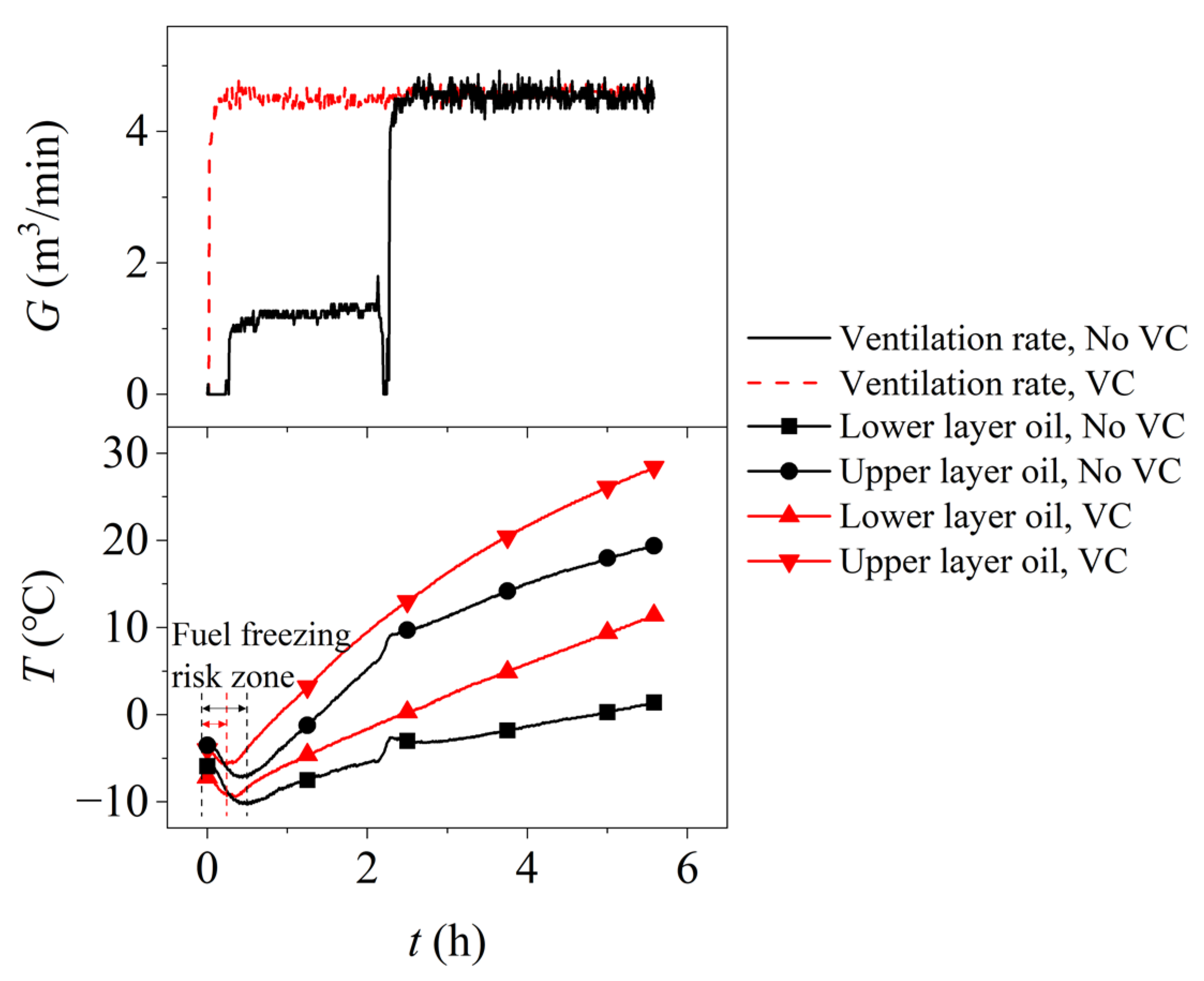
Figure 4, the ventilation rate is G
n = 1.2 m
3/min in the case of natural convection, and the ventilation rate is set to G
f = 4.5 m
3/min in the case of forced convection. Natural convection runs for 2 h, and forced convection runs for 4 h. During the first 2 h, the temperature of the lower layer oil increases from −5.9 °C to −4.6 °C, corresponding to a heating rate of approximately 0.65 °C/h. The temperature of the upper layer of oil rises from −3.5 °C to 7.1 °C, with a significantly higher rate of approximately 5.3 °C/h. This indicates that the upper layer of oil heats up considerably faster than the lower layer. This phenomenon is primarily caused by two factors. Firstly, the unburned fuel with a higher temperature from the diesel generator flows back to the top of the fuel tank through the return pipe, heating the upper layer of fuel. Secondly, the air heated by the engine rises to the top of the cabin, where the air temperature is significantly higher than at the bottom. The hot air circulating above the fuel tank exchanges convective heat with the upper layer of fuel, while the lower layer of fuel is largely insulated from this airflow, receiving only minimal radiative heat from the diesel generator. These two factors combined result in the upper layer of fuel heating much faster than the lower layer. Notably, due to the extremely low outdoor temperature and the high thermal inertia of the fuel tank, the first half hour after starting the diesel generator is considered the “fuel freezing risk zone”, where the fuel temperature can continue to drop by approximately 4.4 °C. If the outside air temperature falls below −40 °C, the fuel at the lower layer is likely to freeze during the initial start-up phase, leading to an irrecoverable shutdown of the diesel generator.
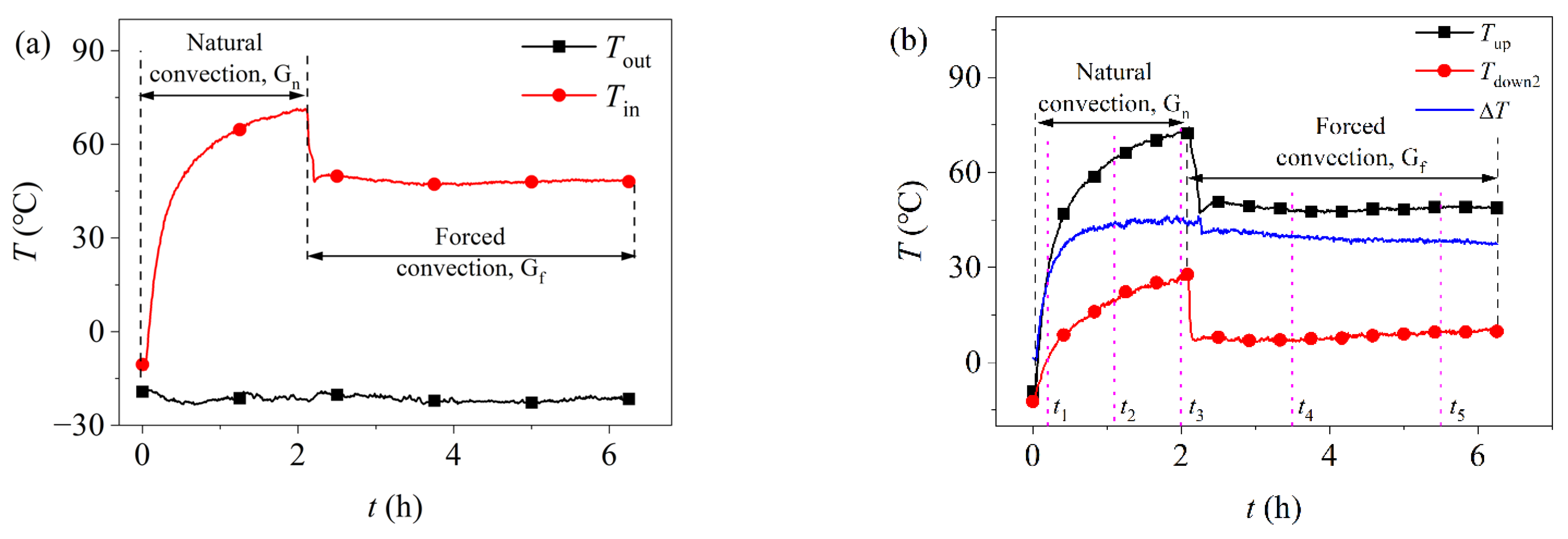
During the 2–6 h period under forced convection, the temperature of the lower layer of oil increased from −4.6 °C to 4 °C, while the temperature of the upper layer of fuel rose from 7.1 °C to 22.5 °C. It is evident that the rate of temperature increase for both the lower and upper layers of fuel slowed, with a more pronounced deceleration in the upper layer. This is due to the sudden transition from natural convection to forced convection, which significantly impacted the temperature distribution of the air inside the cabin. As shown in
Figure 5b, the temperature of the air in both the upper and lower sections of the cabin decreased by 20 °C at the 2 h mark, leading to the observed slowdown in fuel temperature rise. The more significant deceleration in the upper layer is attributed to the fact that the fuel tank is not fully filled, leaving a certain amount of air at the top. This allows the upper layer of fuel to exchange heat directly with the air, resulting in a quicker temperature response. In contrast, the lower layer of fuel receives heat primarily through conduction from the cabin air via the tank walls, leading to a slower temperature response.
As shown in
Figure 5, under natural convection conditions during the first 0–2 h, the air temperature at the top of the cabin reached 74.3 °C, and the indoor air temperature reached 71.2 °C, which exceeds the maximum operating temperature of 55 °C for the PLC inside the cabin. The air temperature at the bottom of the cabin reached 28.1 °C, resulting in a temperature difference of 43.1 °C between the upper and lower sections of the cabin. This indicates extremely poor temperature uniformity, necessitating forced ventilation to reduce the air temperature inside the cabin.
During the 2–6 h period under forced convection, the indoor air temperature decreased to 48.5 °C, the top air temperature in the cabin dropped to 49.4 °C, and the bottom air temperature fell to 10.6 °C. However, the temperature difference between the upper and lower air in the cabin remained at 38.8 °C, indicating that temperature uniformity was still suboptimal.
Table 3 systematically presents the temperature statistics at five uniformly sampled representative time points.
3.2. Influence of the VC on the Temperature Characteristics of the Cabin
If the temperature of the fuel at the bottom of the fuel tank drops below −40 °C, the fuel will freeze, leading to an irreversible failure of the diesel generator. To mitigate this issue, a VC is utilized to transfer heat from the bottom of the diesel generator throughout the power generation cabin, while isolating the heat dissipation from the fuel tank. This section investigates the effect of the VC on the temperature distribution within the cabin. As established in
Section 3.1, forced convection improves temperature uniformity inside the cabin. Therefore, as shown in
Figure 6, the condition of continuous operation for nearly 6 h with a VC installed at the bottom of the cabin and a ventilation rate of G
f = 4.5 m
3/min is compared to the scenario without the VC.
Within 6 h of installing the VC at the bottom of the cabin, the temperature of the lower layer oil increases from −7.2 °C to 11.4 °C, while the temperature of the upper layer of oil rises from −4 °C to 28.4 °C. Under these conditions, the presence of the VC accelerates the temperature rise of the oil. Notably, the VC isolates the direct heat transfer from the fuel tank to the cabin, effectively mitigating the drop in fuel temperature within the tank that occurs during the initial start-up of the diesel engine. With the VC in place, the duration of the temperature drop for the lower layer of oil during the initial start-up is reduced from 0.5 h to 0.35 h, and the temperature drop is decreased from 4.4 °C to 2.2 °C. Similarly, the duration of the temperature drop for the upper layer of oil is shortened from 0.44 h to 0.31 h, and the temperature drop is reduced from 3.7 °C to 1.6 °C. Therefore, the use of VC is advantageous for enabling diesel generators to effectively pass through the “fuel freezing risk zone” during the initial start-up phase, thereby preventing irreversible stoppages of the diesel generators.
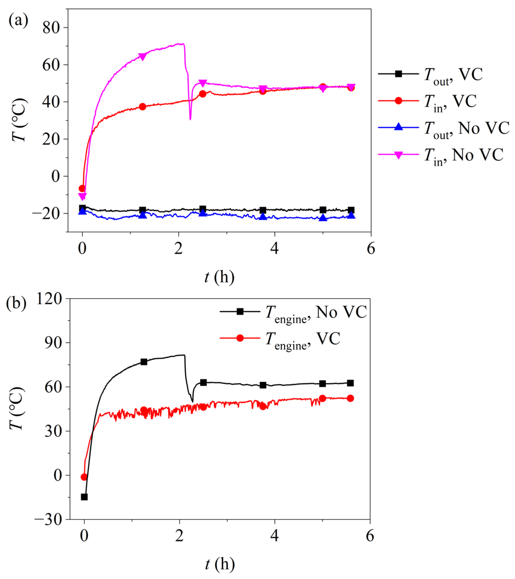
As shown in
Figure 7a, within 6 h of installing the VC, the indoor air temperature stabilizes at the same level as observed without the VC, indicating that the presence of the VC has no significant effect on the indoor air temperature.
Figure 7b illustrates the temperature distribution at the base of the diesel generator, where it can be observed that, under a ventilation rate of G
f = 4.5 m
3/min, the average temperature at the base of the diesel engine is approximately 10 °C lower within 4 h when the VC is installed compared to when it is not. This temperature reduction is attributed to the VC diffusing the heat from the base of the diesel engine throughout the cabin.
Figure 8 illustrates the air temperature and the temperature differential between the top and bottom of the cabin. After 6 h of operation, the presence or absence of the VC has minimal impact on the air temperature at the top of the cabin. However, within 4 h at a ventilation rate of G
f = 4.5 m
3/min, the air temperature at the bottom of the cabin shows significant improvement. Specifically, the temperature at T
down1, which is closest to the diesel generator, reaches a maximum of 42.5 °C. The temperatures at T
down2 and T
down3 are relatively similar, measuring 20.9 °C and 16.7 °C, respectively. It is evident that the air temperature decreases with increasing distance from the diesel engine. This is primarily because the ethanol vapor in the VC begins to condense and release heat before reaching the farthest end, leading to temperature stratification. Despite this, the air temperature at the farthest end of the VC is 6.7 °C higher than that of the bilge air without the VC, indicating that the VC significantly elevates the temperature across the entire cabin floor. The temperature differential between the top and bottom of the cabin, as shown in the diagram, reveals that without the VC, the temperature difference between the upper and lower air in the cabin is approximately 40 °C. After installing the VC, this differential decreases to a maximum of 33 °C and a minimum of 7.8 °C, reflecting a substantial improvement in temperature uniformity within the cabin.
4. Conclusions
This study addresses the issue of fuel freezing at the bottom of the fuel tank and the significant temperature disparity between the upper and lower regions of a power generation cabin. A VC was designed and implemented in a low-temperature environment power generation cabin in Daqing, China, where the external temperatures fall below −20 °C. Experimental investigations were conducted to evaluate the thermal performance of the cabin under both natural and forced convection conditions, as well as with the VC installed. The results indicate that, in the absence of the VC, the temperature of the bottom fuel oil increases slowly, while natural convection leads to excessively high temperatures at the top of the cabin, potentially damaging electrical equipment and resulting in poor temperature uniformity. Forced convection can significantly reduce the indoor air temperature (by 30 °C), thereby greatly decreasing the temperatures at the top and bottom of the cabin, and simultaneously improving the temperature uniformity inside the engine room. However, it should be noted that the effect of improving temperature stability is not remarkable, and the temperatures of the air and fuel at the bottom are still relatively low. The VC can effectively utilize the heat dissipated during the operation of the diesel engine. By virtue of its remarkable high thermal conductivity performance, the VC rapidly transfers the heat generated by the diesel engine to the bottom of the fuel oil, effectively increasing the temperature of the fuel oil at the bottom. This action makes the overall temperature distribution of the fuel more uniform, significantly alleviates the problem of fuel freezing, and remarkably optimizes the thermal environment of the generator. Additionally, compared with the situation without the installation of the VC, the maximum temperature difference between the top and the bottom of the cabin is reduced by 33 °C, which significantly enhances the temperature uniformity inside the cabin. Overall, this study demonstrates that installing a VC at the bottom of a power generation cabin is an effective measure for addressing low-temperature problems, providing a viable solution for ensuring the stable operation of diesel generators in cold regions.


