Article

Study of Nickel–Chromium-Containing Ferroalloy Production

by
Assylbek Abdirashit
1,*,
Bauyrzhan Kelamanov
1,*,
Otegen Sariyev
1,
Dauren Yessengaliyev
1,*,
Aigerim Abilberikova
2,
Talgat Zhuniskaliyev
2,
Yerbol Kuatbay
2,
Magauiya Naurazbayev
1 and
Alibek Nazargali
1
1
Department of Metallurgy and Mining, K. Zhubanov Aktobe Regional University, Aktobe 030000, Kazakhstan
2
Department of Metallurgy and Materials Science, Karaganda Industrial University, Temiratau 101400, Kazakhstan
*
Authors to whom correspondence should be addressed.
Processes 2025, 13(4), 1258; https://doi.org/10.3390/pr13041258
Submission received: 8 April 2025 / Revised: 16 April 2025 / Accepted: 17 April 2025 / Published: 21 April 2025
(This article belongs to the Section Manufacturing Processes and Systems)

Abstract

:
This article presents the results of laboratory studies on the smelting of nickel–chromium-containing ferroalloys from low-grade nickel ores from Kazakhstan. X-ray phase analysis was performed on raw materials, which included quartz, nontronite, chromium metahydroxide, goethite, magnetite, iron chromite, and nickel (II) silicate. The reduction reactions of metal oxides with carbon and carbon monoxide were studied as the temperature increased. Experimental smelting was carried out in a Tammann furnace at 1500–1550 °C using three types of reducing agent: RK coke, as well as its mixtures with low-ash Shubarkol coal, in ratios of 75:25 and 50:50. The second option demonstrated the highest economic efficiency, achieving a 91% nickel recovery rate, reduced coke consumption, and a slag-to-metal ratio of 3.07. Chemical analysis showed that the nickel content in the obtained alloys ranged from 2.5% to 6.5%, while chromium content ranged from 2.6% to 4.5%. X-ray phase analysis confirmed the presence of Fe2Ni0.6Si, Fe5Si3, and Fe2CrSi phases in the alloy structure. Local element concentrations varied within the following ranges: Fe—55–59%, Ni—2–10%, Cr—2–7%, and Si—29–35%. The results of this study confirmed the feasibility of producing a nickel–chromium-containing alloy with a nickel content of 2–10% and a chromium content of 2–7%.

1. Introduction

Currently, high global nickel prices make the establishment of nickel-containing alloy production in Kazakhstan a promising endeavor, especially considering the country’s significant explored reserves of nickel raw materials. However, a large portion of these ores remains unutilized due to the lack of efficient processing technologies and production capacities for their primary treatment [1,2,3].
One possible solution is the development of integrated processing technologies that enable the production of nickel alloys directly within Kazakhstan. This would significantly enhance the country’s export potential in the global ferrous and non-ferrous metal market.
One of the key regions for nickel ore mining is the Aktobe region, where the nickel content in ores is approximately 1%. Although a significant portion of the deposits in western Kazakhstan has already been depleted, the Kempirsai district offers potential for increasing nickel reserves by revising the cut-off grades for low-grade and off-balance ores. This area contains 35 deposits with total explored reserves of 423.5 million tons of nickel-containing raw materials [4].
At present, nickel ores are not processed domestically, but are exported without prior beneficiation or agglomeration, leading to significant economic losses. A potential solution to this issue could involve not only intensifying geological exploration efforts, but also developing efficient technologies for processing low-grade nickel ores [5,6,7,8,9,10].
According to [11,12], the bloomery process has been used for processing oxidized nickel ores. This method is based on the reduction of nickel and part of the iron to a metallic state without melting the ore. The reduced metals (bloom) were separated from the gangue using beneficiation methods, after which the bloom was further refined to a state suitable for use in various industries.
At several enterprises, including the “Yuzhuralnickel” plant (Orsk, Orenburg region), nickel production follows a complex technological scheme. This process involves multi-stage and labor-intensive ore preparation for smelting; it includes the reduction–sulfidizing smelting of the ore into matte, subsequent converting of the matte, roasting of the fine matte, and the smelting of the resulting nickel oxide to produce fire-refined nickel metal, the final product of the nickel plant [13,14].
The most widely used method for producing ferronickel worldwide is smelting in electric furnaces. The “Doniambo” plant (France, New Caledonia), commissioned in 1958 [15,16,17,18], operates using a technological scheme that includes ore preparation, roasting in tubular rotary kilns, electric smelting of the calcine to produce ferronickel, and subsequent refining.
Electric smelting offers several advantages: it does not require ore agglomeration, is suitable for ores with varying compositions, provides a convenient crude ferronickel for refining, and has good environmental performance. However, its main drawback is the production of low-grade ferronickel (Ni < 8%) from ores with high iron content due to slag foaming. In this context, a two-stage electric smelting process proposed by the “GINtsvetmet” institute is considered promising. This process includes carbothermic reduction (Ni < 5%) followed by refining to 10–20% Ni. However, it is still insufficiently studied and has not yet been tested on a semi-industrial scale [19].
The bath smelting process, developed by A.V. Vanyukov, is used for processing copper–nickel, nickel, and other sulfide ores. It is carried out in a shaft furnace, the walls of which consist of copper water-cooled plates, while the hearth and roof are made of refractory materials [20]. The key advantages of this technology include low sensitivity to charge quality and an ability to process both lump ores (up to 50 mm) and fine concentrates without prior drying. Oxygen-enriched air is used as the blast. The resulting matte can contain 45–55% nickel.
The development of technologies for processing low-grade nickel ores has been a longstanding challenge; however, no optimal technological solution has been proposed to date. This underscores the importance of creating efficient methods for incorporating substandard ores into metallurgical processing, making the development of new nickel processing technologies highly relevant for Kazakhstan.
The aim of the present study is to develop technology for producing a nickel–chromium-containing alloy from low-grade Batamsha nickel ore. This research addresses the urgent issue of processing substandard raw materials with low nickel content (~1.05%) through reductive smelting using carbon-containing reagents. This study includes a thermodynamic analysis of the reduction processes of ore components, laboratory-scale smelting experiments with various charge compositions, and X-ray diffraction and microstructural analyses of the resulting alloys. The obtained results demonstrate the potential of producing a nickel–chromium alloy suitable for use as an alloying additive in metallurgy, and confirm the viability of the proposed method for processing low-grade nickel ores.

2. Materials and Methods

In this study, low-grade nickel ore from the “Batamsha” deposit, RK coke, Shubarkol coal, and lime were used as charge materials for the production of a nickel–chromium-containing ferroalloy (Figure 1). The technical composition and chemical analysis of the ash from the reducing agent, lime, and nickel ore are presented in Table 1.
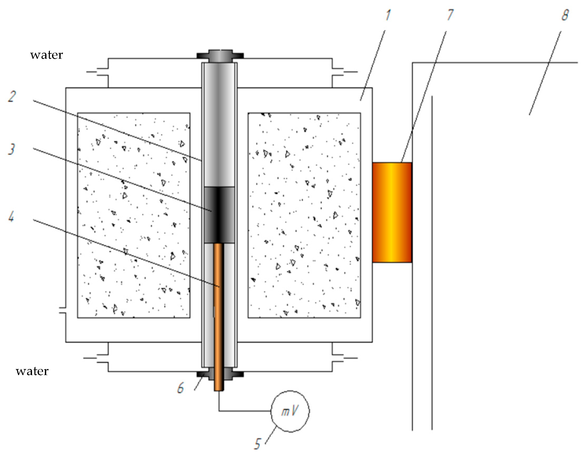
In the “Metallurgy” laboratory of LLP “ERG Research and Engineering Center”, a series of experiments was conducted to produce a nickel–chromium-containing alloy using a high-temperature Tammann electric furnace equipped with a graphite heater (Figure 2). As a reducing agent for processing low-grade nickel ore from the “Batamsha” deposit, RK coke was used, as well as its mixture with low-ash coal from the Shubarkol deposit, in ratios of 75:25 and 50:50.
The Tammann resistance furnace is a research apparatus designed for generating high temperatures and is used for modeling metallurgical processes. This high-temperature unit is equipped with a heater, where the working space is a carbon tube, and a power transformer. The temperature in the furnace is smoothly regulated using a thyristor voltage regulator, which is connected to the primary winding of the power transformer. This setup allows the output busbars to deliver a current of several thousand amperes at low voltage (ranging from 0.5 to 15 V).
The temperature was measured using a tungsten–rhenium thermocouple TR-5/20, with its hot junction placed at the bottom of the crucible in a reinforced corundum sheath. The full specifications of the high-temperature Tammann furnace are presented in Table 2.
The phase composition of the studied samples was determined using a D8 ADVANCE diffractometer (Bruker Elemental GmbH, Berlin, Germany) equipped with a HTK 2000 high-temperature chamber. Measurements were carried out in the 2θ range, from 10° to 80°, with a scan step of 0.02° and a measurement time of 1 s per step.
The morphology and local elemental composition of the samples were examined using a JEOL JXA-8230 electron probe microanalyzer (Tokyo, Japan). This instrument integrates scanning electron microscopy with advanced energy-dispersive (EDS) and wavelength-dispersive (WDS) spectroscopy capabilities, enabling high-precision microstructural and elemental analysis.
The chemical analysis of the samples was conducted in accordance with State Standard 22772.4-77, State Standard 22772.6-77, and State Standard 22772.7-96 [21,22,23].

3. Results and Discussion

According to the results of X-ray structural analysis (X-ray diffractometer D8 Advance BRUKER, Karlsruhe, Germany) (Figure 3), the low-grade nickel ore consists of quartz, nontronite, chromium metahydroxide, goethite, magnetite, and iron chromite. Nickel is present in the form of nickel (II) silicate.
The calculation of the charge material ratio was based on the distribution of oxides and elements presented in Table 3 and Table 4.
As part of this study, a series of experimental melts were carried out using various reducing agents: pure coke from the Republic of Kazakhstan, and its mixtures with low-ash coal from the Shubarkol deposit, in ratios of 75:25 and 50:50. The charge mixture, which included pre-crushed components with a particle size of up to 5 mm, was thoroughly mixed and loaded into a graphite crucible in measured portions. Melting was carried out in a Tamman resistance furnace at a temperature of 1500–1550 °C until complete melting of the charge materials was achieved. After melting, the alloy was held at 1550 °C for 30 min to stabilize the phase composition and ensure uniform distribution of the components. After holding, the samples were cooled under natural conditions to room temperature. The obtained technological parameters and process efficiency indicators are presented in Table 5.
The analysis of the presented data shows that the option with a reducer ratio of 75:25 (Option II) is the most optimal in terms of process efficiency. This is confirmed by the following indicators:
Nickel recovery: The second option ensures a high nickel recovery rate of 91%, which is only 1% lower than the maximum (with 100% coke), but significantly higher than the equal ratio of coke and coal (88%).
Coke savings: The 75:25 option reduces coke consumption from 7.193 g to 5.93 g, improving the economic efficiency of the process.
Slag ratio: The value of 3.07 indicates a more stable slag process compared to the 50:50 option (3.02), contributing to better metal quality and lower nickel losses.
In this regard, further comprehensive studies (X-ray phase, microstructural, and chemical analysis) were conducted on the metallic and slag products obtained from smelting using the second variant of the reducing mixture.
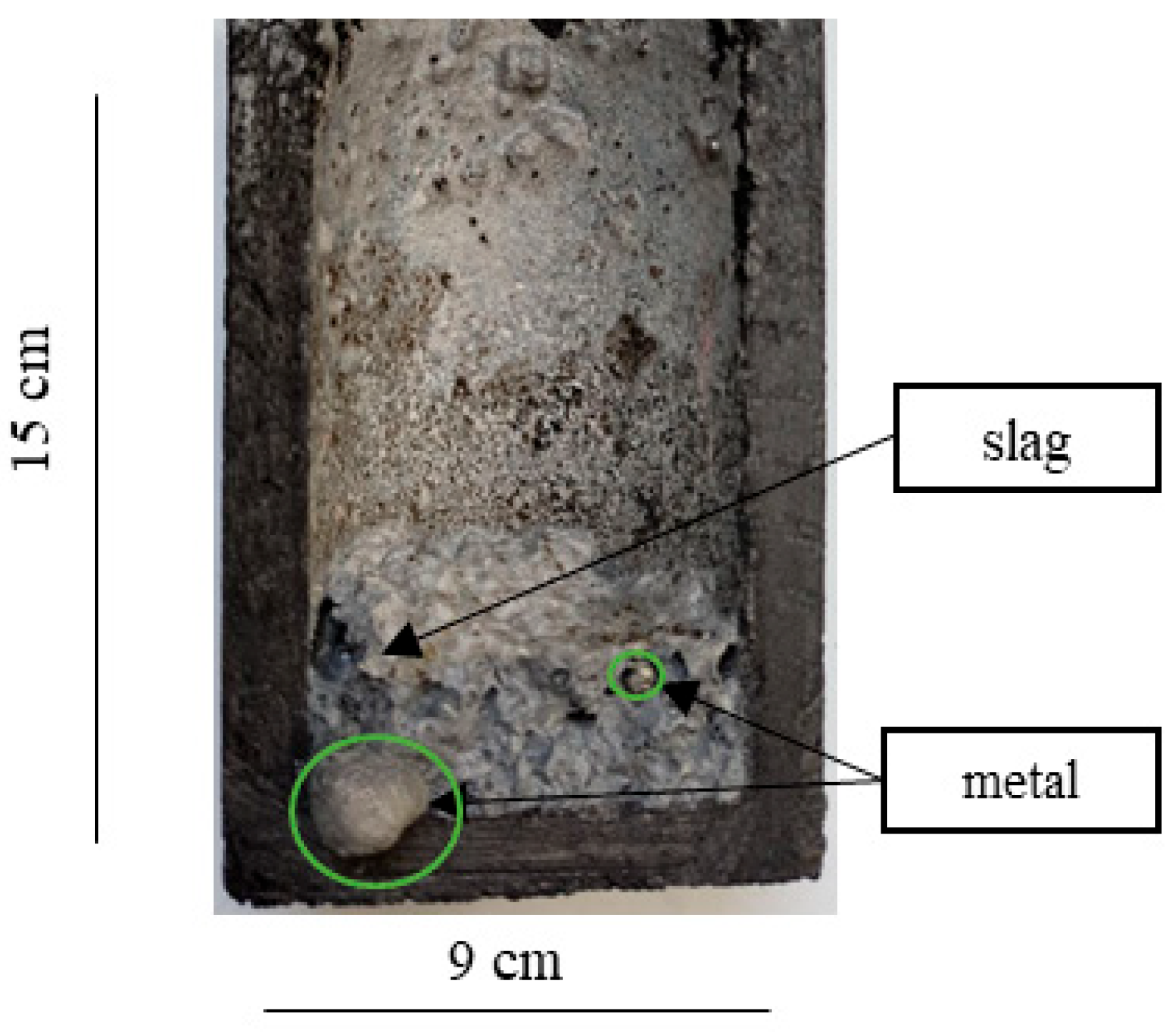
Figure 4 shows the products obtained from smelting using option II. As seen, the metal and slag are clearly separated. It should be noted that no significant gas emissions were recorded during the smelting process.
The selected smelting products (metal and slag) were not subjected to crushing or magnetic separation, as they exhibited a clearly defined phase boundary in solidified form. This made it possible to manually separate the metallic nuggets from the slag mass without additional operations. The metallic nuggets were analyzed using X-ray diffraction (XRD) (Bruker Elemental GmbH, Berlin, Germany) and scanning electron microscopy (SEM) with energy-dispersive spectroscopy (EDS) (JEOL JXA-8230, Tokyo, Japan) elemental mapping to determine their phase and microstructural composition. Additionally, chemical analyses were performed on both the metallic and slag phases to quantitatively determine the content of key elements (Fe, Ni, Cr, Si), enabling a comprehensive assessment of the reduction process efficiency and the recovery rate of valuable components.
During the thermal treatment of the charge within the studied temperature range (1500–1550 °C), Reactions (1)–(17) occurred during the smelting process, reflecting the sequential reduction of ore components and the formation of phases in the alloy.
  • Iron is present in the form of Fe2O3, Fe3O4, and FeO(OH). These oxides are reduced sequentially as the temperature increases:
Upon heating in the temperature range of 260–300 °C, goethite loses water and transforms into hematite [24].
2FeO(OH) → Fe2O3 + H2O
According to study [25], with further heating (400–900 °C), hematite is reduced to magnetite (Fe3O4), and magnetite is subsequently reduced to wüstite (FeO):
3Fe2O3 + CO → 2Fe3O4 + CO2
3Fe2O3 + C → 2Fe3O4 + CO
Fe3O4 + CO → 3FeO + CO2
Fe3O4 + C → 3FeO + CO
Then, at temperatures of 1000–1500 °C, wüstite (FeO) is reduced to metallic iron:
FeO + C → Fe + CO
FeO + CO → Fe + CO2
Thus, the complete reduction of iron (Fe) is completed at 1400–1500 °C [22].
2.
Chromium in the ore is present in the form of CrO(OH) and FeCr2O4.
The thermal decomposition reaction of chromium (III) hydroxide results in the formation of chromium (III) oxide and water. This reaction occurs at a temperature range of 430–1000 °C.
2CrO(OH) → Cr2O3 + H2O
Chromium oxide begins to be reduced at a temperature of 1120 °C [26]. In study [27], a thermodynamic assessment was conducted to evaluate the probability of 16 reactions occurring in the chromium oxide–carbon phase. Up to 1500 °C, the following reactions are possible:
2/3Cr2O3 + 2C → 4/3Cr + 2CO
1/3Cr2O3 + CO → 2/3Cr + 3CO2
2/3Cr2O3 + 26/9 C → 4/9Cr3C2 + 2CO
2/3Cr2O3 + 54/21C → 4/21Cr7C3 + 2CO
3/13Cr2O3 + 17/13 CO → 2/13Cr3C2 + CO2
7/27Cr2O3 + 33/27C → 2/27Cr7C3 + CO2
According to the authors of [28], the reduction of iron chromite (FeCr2O4) occurs in five stages at increasing temperatures (Stage 1: 800–1010 °C, Stage 2: 1090–1120 °C, Stage 3: 1260–1270 °C, Stage 4: 1310 °C, Stage 5: 1310–1500 °C), with the final reaction occurring at the highest temperature range.
FeCr2O4 + 4.4 C → (Fe, Cr, C, Fe3C, Cr3C2, Cr7C3) + 4CO
3.
Nickel in the ore is present in the form of silicates (Ni2SiO4). According to the authors of [25], nickel silicate is reduced by carbon as follows:
Ni2SiO4 + 2C → 2Ni + SiO2 + 2CO
4.
Silicon in the ore is present in the form of quartz. Up to 80% of SiO2 binds with CaO and transitions into the slag, while 20% is reduced according to the reaction at temperatures above 1500 °C [29].
SiO2 + 2C → Si + 2CO
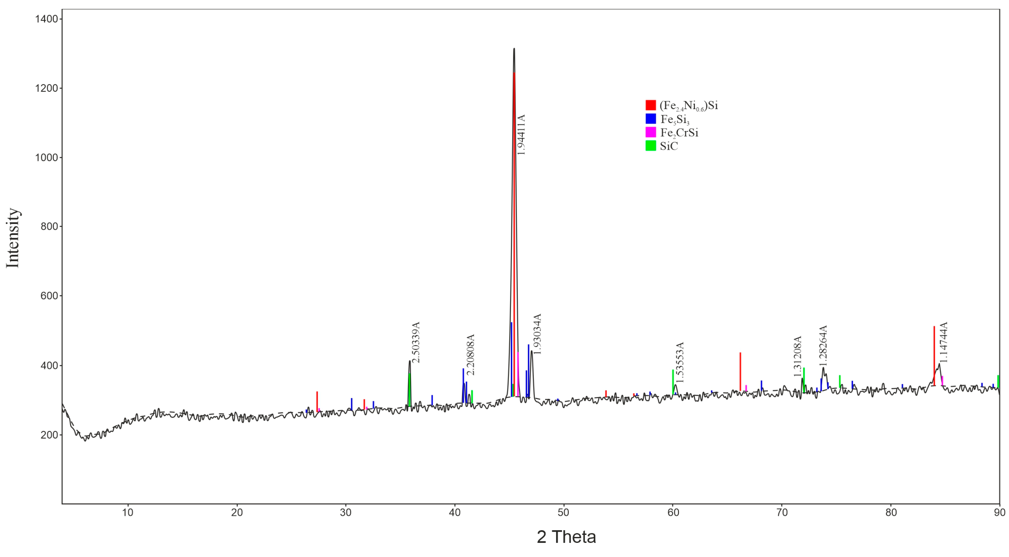
The reduced elements are assumed to interact with each other, forming an intermetallic compound, which is confirmed by the X-ray phase analysis data (Figure 4).
2Fe + 0.6Ni + Si → Fe2Ni0.6Si
5Fe + 3Si → Fe5Si3
2Fe + Cr + Si → Fe2CrSi
During the reduction of nickel silicates (Reaction (16)) and quartz (Reaction (17)), metallic Ni and Si interact with the reduced Fe (Reactions (6) and (7)), forming the thermodynamically stable compound Fe2Ni0.6Si. This is confirmed by the phase identified in the X-ray diffraction pattern (Figure 5) and the co-localization of Fe and Ni in the EDS maps (Figure 6b,c).
The portion of Si not incorporated into intermetallics with Ni and Cr interacts with Fe to form a silicon-containing intermetallic compound. This phase is visualized in the XRD pattern (Figure 5) and corresponds to regions with elevated Si content and decreased concentrations of Ni and Cr in the EDS maps (Figure 6e).
The reduction of Cr2O3 (Reactions (9) and (10)) and FeCr2O4 (Reaction (15)) results in the formation of metallic Cr, which, together with Si and Fe, forms the intermetallic compound Fe2CrSi. This phase was also identified by X-ray phase analysis and is characterized by the counter-phase distribution of Cr and Si (Figure 6d,e).
The microstructure of the nickel–chromium-containing alloy sample is characterized by heterogeneous grains containing a well-developed network of cracks (Figure 6). The average elemental composition of this selected area, obtained using energy-dispersive X-ray spectroscopy (EDS), can be represented as follows: Fe0.58Ni0.04Cr0.05Si0.33.
Using the EDS element mapping method, patterns of the Fe-Ni-Cr-Si alloy’s component composition were identified, which can be described in terms of “co-phasing” and “counter-phasing” (Figure 6).
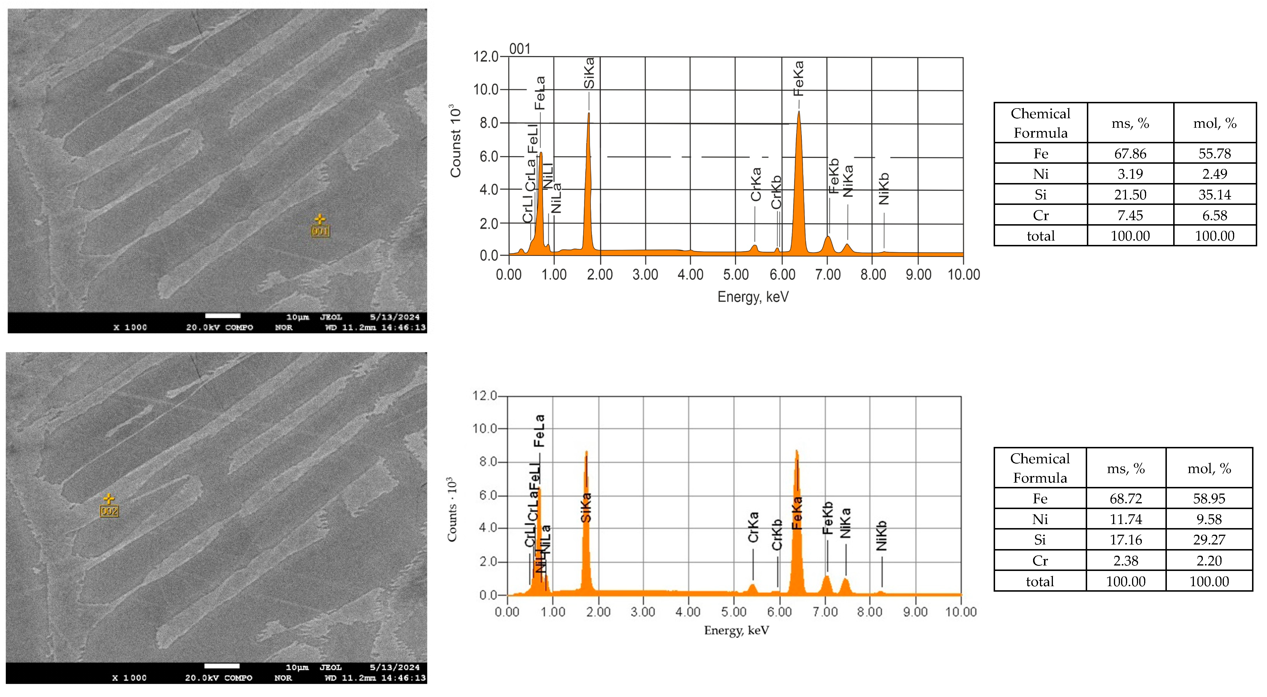
The local concentrations of alloy components, obtained through point EDS microanalysis (Figure 7), can be represented as follows: for region 1 (low nickel content), Fe0.56Ni0.02Cr0.07Si0.35, for region 2 (high nickel content), Fe0.59Ni0.1Cr0.02Si0.29. Thus, the observed local variations in elemental composition can reach the following values: Fe: 55–59%, Ni: 2–10%, Cr: 2–7%, and Si: 29–35%.
In this case, Fe and Ni exhibit co-phasing, which is typical for many metallic alloys. Meanwhile, Si and Cr demonstrate a so-called “counter-phase” distribution of concentrations, where Fe reaches its maximum concentrations in areas acting as a “binder” for grains with the highest Si concentrations.
This behavior of the alloy component correlates with the contrast in the micrograph obtained through backscattered electron imaging—the higher the average atomic number of the areas, the brighter their contrast appears.
The intermetallic compounds identified by XRD are confirmed by the microstructure (Figure 6) and the local elemental distribution (Figure 7), and their formation is explained by the regular reduction Reactions (1)–(17) occurring during smelting. The chemical composition of the obtained products, as presented in Table 6, validates the occurrence of the proposed reactions under the experimental conditions.
As shown in Table 6, the nickel content in these products ranges from 2.5% to 6.5%, while the chromium content varies from 2.6% to 4.5%. The carbon content in all samples fluctuates up to 4%, whereas the silicon content in the experimental smelting samples varies from 2.22% to 24.9%. This variation is primarily associated with the holding time of the crucible in the furnace and the temperature conditions during smelting. Sulfur and phosphorus are present in the experimental alloy samples in trace amounts, ranging from 0.004% to 0.039% and from 0.003% to 0.032%, respectively.
X-ray phase analysis of the obtained product samples revealed that the nickel–chromium-containing alloy consists of the following phases: Fe2Ni0.6Si, Fe5Si3, and Fe2CrSi (Figure 5).

4. Conclusions

The crucible smelting of a nickel–chromium-containing alloy was carried out at a temperature of 1500–1550 °C. The experimental melts confirmed the fundamental feasibility of producing an alloy containing 2–10% nickel and 2–7% chromium, suitable for alloying heat-resistant and stainless steels. Although the nickel content does not exceed 10%, which is comparable to some examples of electric smelting, the proposed technology offers several significant advantages:
Enables the processing of low-grade and substandard nickel ores from Kazakhstan without the need for prior agglomeration;
Demonstrates flexibility with respect to raw material composition;
Features lower energy consumption compared to electric smelting;
Has a reduced environmental impact due to the absence of slag foaming;
Ensures the production of an industrially applicable semi-product that meets the needs of the domestic market.
Thus, the developed technology represents a promising direction in the production of nickel–chromium alloys and may help reduce dependence on expensive imported nickel, while meeting the growing demand for stainless and specialty steels in Kazakhstan.

Author Contributions

Conceptualization, A.A. (Assylbek Abdirashit) and B.K.; methodology, B.K.; software, O.S.; validation, A.A. (Assylbek Abdirashit), D.Y. and A.A. (Aigerim Abilberikova); formal analysis, A.N.; investigation, B.K.; resources, Y.K.; data curation, T.Z.; writing—original draft preparation, A.A. (Assylbek Abdirashit); writing—review and editing, O.S.; visualization, D.Y.; supervision, M.N.; project administration, B.K.; funding acquisition, B.K. All authors have read and agreed to the published version of the manuscript.

Funding

This research is funded by the Science Committee of the Ministry of Science and Higher Education of the Republic of Kazakhstan (Grant No. AP 19679501).

Data Availability Statement

The data used to support the findings of this study are included within this article.

Conflicts of Interest

The funders had no role in the design of this study; in the collection, analyses, or interpretation of data; in the writing of the manuscript; or in the decision to publish the results.

References

  1. Shofi, A.; Supriyatna, Y.I.; Prasetyo, A.B. Selective reduction of southeast sulawesi nickel laterite using palm kernel shell charcoal: Kinetic studies with addition of Na2SO4 and NaCl as additives. Bull. Chem. React. Eng. Catal. 2020, 15, 501–513. [Google Scholar] [CrossRef]
  2. Sari, Y.; Manaf, A.; Astuti, W.; Nurjaman, F.; Susanti, D.; Sipahutar, W.S.; Bahfie, F. Nickel Recovery in Ferronickel Concentrate by Green Selective Reduction of Nickel Laterite. Eng. Sci. Technol. Int. J. 2024, 57, 101798. [Google Scholar] [CrossRef]
  3. Sari, Y.; Manaf, A.; Astuti, W.; Haryono, T.; Nurjaman, F.; Bahfie, F. Recovery of Ferronickel by Green Selective Reduction of Nickel Laterite. IOP Conf. Ser. Earth Environ. Sci. 2024, 1388, 012026. [Google Scholar] [CrossRef]
  4. Tolymbekov, M.Z.; Kelamanov, B.S.; Baisanov, A.S.; Kaskin, K.K. Processing Kazakhstan’s Chromonickel Ore. Steel Transl. 2008, 38, 660–663. [Google Scholar] [CrossRef]
  5. Kelamanov, B.; Yessengaliyev, D.; Sariev, O.; Akuov, A.; Samuratov, Y.; Zhuniskaliyev, T.; Kuatbay, Y.; Mukhambetgaliyev, Y.; Kolesnikova, O.; Zhumatova, A.; et al. Technological Analysis of the Production of Nickel-Containing Composite Materials. J. Compos. Sci. 2024, 8, 179. [Google Scholar] [CrossRef]
  6. Kelamanov, B.; Samuratov, Y.; Zhumagaliyev, Y.; Akuov, A.; Sariev, O. Titanium and Chrome Oxides System Thermodynamic Diagram Analysis. Metallurgija 2020, 59, 101–104. [Google Scholar]
  7. Kelamanov, B.; Sariev, O.; Akuov, A.; Samuratov, Y.; Sultamuratova, Z.; Orynbassar, R. Study of Nickel Briquettes by Thermographic Method. Metallurgija 2022, 61, 217–220. [Google Scholar]
  8. Agatzini-Leonardou, S.; Tsakiridis, P.E.; Oustadakis, P.; Karidakis, T.; Katsiapi, A. Hydrometallurgical process for the separation and recovery of nickel from sulphate heap leach liquor of nickeliferrous laterite ores. Miner. Eng. 2009, 22, 1181–1192. [Google Scholar] [CrossRef]
  9. Chen, J.; Hayes, P.C. Mechanisms and Kinetics of Reduction of Solid NiO in CO/CO2 and CO/Ar Gas Mixtures. Metall. Mater. Trans. B Process Metall. Mater. Process. Sci. 2019, 50, 2623–2635. [Google Scholar] [CrossRef]
  10. Qu, G.; Zhou, S.; Wang, H.; Li, B.; Wei, Y. Production of ferronickel concentrate from low-grade nickel laterite ore by non-melting reduction magnetic separation process. Metals 2019, 9, 1340. [Google Scholar] [CrossRef]
  11. Sadykhov, G.B.; Kop’Ev, D.Y.; Olyunina, T.V.; Anisonyan, K.G. Bloomery Processing of Oxidized Magnesia Nickel Ores. Russian Metall. (Metally) 2019, 2019, 1–7. [Google Scholar] [CrossRef]
  12. Khasanov, M.S.; Sadykhov, G.B.; Anisonyan, K.G.; Zablotskaya, Y.V.; Olyunina, T.V. Effect of the Temperature of Reduction Roasting of Ferriferrous Oxidized Nickel Ores on the Nickel and Cobalt Recovery during Hydrometallurgical Processing of a Cinder. Russ. Metall. 2022, 714–718. [Google Scholar] [CrossRef]
  13. Zayakin, O.V. Development of a Rational Composition and Technology for the Production of Nickel-Containing Ferroalloysfrom Low-Grade Oxidized Nickel Ores. Ph.D. Thesis, Institute of Metallurgy, Ural Branch of the Russian Academy of Sciences, Yekaterinburg, Russia, 2002. [Google Scholar]
  14. Sadykhov, G.B.O.; Kisilev, A.I.; Lainer, Y.A. Method for Processing Nickel Laterite Ores Resulting in the Direct of Ferronickel. Patent WO 2014133421, 4 September 2014. [Google Scholar]
  15. Zhang, Z.F.; Zhang, W.B.; Zhang, Z.G.; Chen, X.F. Nickel extraction from nickel laterites: Processes, resources, environment and cost. China Geol. 2025, 1, 187–213. [Google Scholar] [CrossRef]
  16. Zevgolis, E.N.; Daskalakis, K.A. The Nickel Production Methods from Laterites and the Greek Ferronickel Production among Them. Mater. Proc. 2021, 5, 104. [Google Scholar] [CrossRef]
  17. Lin, B. Rotary Kiln for Producing Ferronickel from Indonesia Sulawesi Nickel Laterite Ore Through RKEF (Rotary Kiln-Electric Furnace) Technical Processing. Patent CN 202973836, 5 June 2013. [Google Scholar]
  18. Quintero-Coronel, D.A.; Guillin-Estrada, W.D.; Echeverri-Roman, J.L.; Maury, H.; Corredor, L.; Ruiz, J.A.; Rueda, B.S.; Gonzalez-Quiroga, A. Large- and Particle-Scale energy assessment of reduction roasting of nickel laterite ore for Ferronickel production via the rotary Kiln-Electric furnace process. Therm. Sci. Eng. Prog. 2022, 32, 101331. [Google Scholar] [CrossRef]
  19. Romero, J.M.; Pardo, Y.S.; Parra, M.; Castillo, A.D.J.; Maury, H.; Corredor, L.; Sánchez, I.; Rueda, B.; Gonzalez-Quiroga, A. Improving the rotary kiln-electric furnace process for ferronickel production: Data analytics-based assessment of dust insufflation into the rotary kiln flame. Alex. Eng. J. 2022, 61, 3215–3228. [Google Scholar] [CrossRef]
  20. Voskoboynikov, V.G.; Kudrin, V.A.; Yakushev, A.M. General Metallurgy: University Textbook, 6th ed.; Revised and Updated; RJSC “Akademkniga”: Moscow, Russia, 2002; 768p. [Google Scholar]
  21. GOST 22772.4-77; Manganese Ores, Concentrates and Agglomerates. Methods for Determination of Iron Content (Total). State Committee for Standards of the Council of Ministers of the USSR: Moscow, Russia, 1979.
  22. GOST 22772.6-77; Manganese Ores, Concentrates and Agglomerates. Methods for the Determination of Phosphorus. Committee for Standards of the Council of Ministers of the USSR: Moscow, Russia, 1979.
  23. GOST 22772.7-96; Manganese Ores, Concentrates and Agglomerates. Methods for Determination of Sulfur. Committee for Standards of the Council of Ministers of the USSR: Moscow, Russia, 1999.
  24. Fazlutdinov, K.K. Physicochemical Features of Cr(VI) Solution Utilization Using Steel Shavings: Reduction Kinetics, Phase Formation, Structure, and Morphology of Precipitates. Ph.D. Dissertation, Ural Federal University named after the first President of Russia B. N. Yeltsin (UrFU), Yekaterinburg, Russia, 2017. 154p. [Google Scholar]
  25. Demidov, A.I.; Markelov, I.A. Thermodynamics of Iron Reduction from Oxides by Carbon Monoxide in the Presence of Carbon. Mater. Sci. Power Eng. 2021, 27, 162. [Google Scholar] [CrossRef]
  26. Senin, A.V.; Mikhailov, G.G.; Pashkeev, I.Y.; Kuznetsova, O.V. Thermodynamic Analysis of Carbothermic Reduction of Iron Chromite. Bull. South Ural State Univ. Ser. Math. Mech. Phys. 2003. Available online: https://cyberleninka.ru/article/n/termodinamicheskiy-analiz-karbotermicheskogo-vosstanovleniya-hromita-zheleza (accessed on 18 April 2025).
  27. Kryukov, R.E.; Goryushkin, V.F.; Bendre, Y.V.; Bashchenko, L.P.; Kozyrev, N.A. Some Thermodynamic Aspects of Cr2O3 Reduction by Carbon. Izv. Vuzov. Black Metall. 2019, 62, 950–956. [Google Scholar]
  28. Bajraktari-Gashi, Z.; Halilaj, B. Material Balance of the Technological Process in the New Foundry of New Ferronickel in Drenas 2017. J. Technol. Exploit. Mech. Eng. 2018, 4, 29–35. [Google Scholar] [CrossRef]
  29. Janelidze, I.; Jandieri, G.; Tsertsvadze, T. Thermodynamic Analysis of Interaction of Components in the SiO2-C System: Improvement of Technical Silicon Production Technological Process. Phys. Chem. Solid State 2021, 22, 345–352. [Google Scholar] [CrossRef]
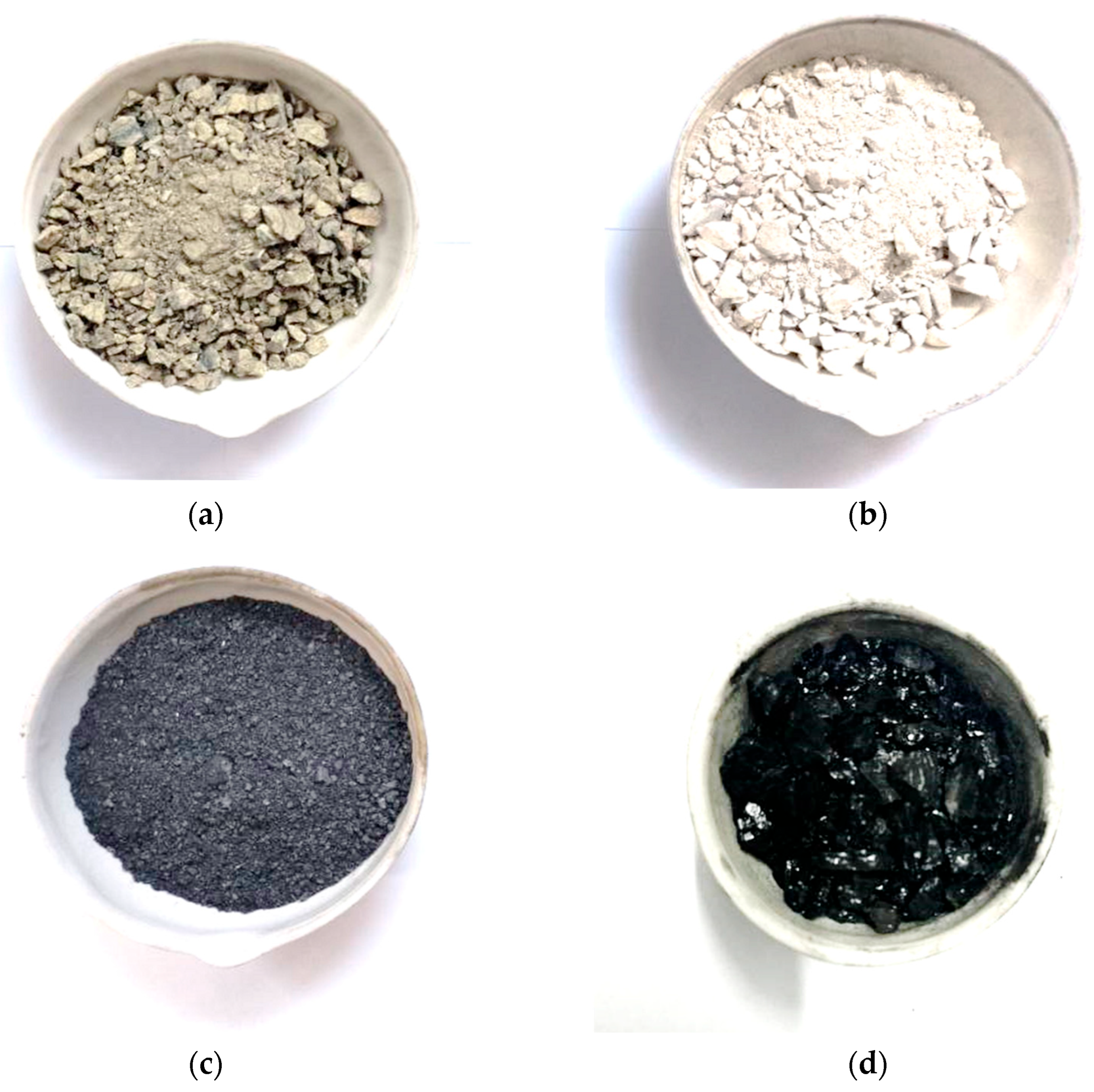
Figure 1. Charge materials: (a) nickel ore; (b) lime; (c) coke; (d) Shubarkol coal.
Processes 13 01258 g001
Figure 2. Tammann resistance furnace. 1—Resistance furnace; 2—graphite tube; 3—charge material; 4—thermocouple; 5—potentiometer (PP-63); 6—asbestos plate; 7—copper busbars; 8—furnace transformer.
Processes 13 01258 g002
Figure 3. X-ray diffraction pattern of the low-grade nickel ore sample.
Processes 13 01258 g003
Figure 4. Products of high-temperature smelting of the nickel–chromium-containing alloy.
Processes 13 01258 g004
Figure 5. X-ray diffraction pattern of the nickel–chromium-containing alloy obtained by smelting.
Processes 13 01258 g005
Figure 6. Microstructure of the nickel–chromium-containing alloy (a) and its EDS element mapping; (b) Fe, (c) Ni, (d) Cr, and (e) Si.
Processes 13 01258 g006
Figure 7. Microanalysis of regions using point EDS elemental analysis.
Processes 13 01258 g007
Table 1. Chemical and technical composition of charge materials.
MaterialContent, %
FCAshWpVSiO2Al2O3MgOFetotPtot
Coke75.7320.41.073.83
Coke Ash 48.5014.574.3411.840.04
Coal55.289.245.4437.71
Coal Ash 51.8032.543.123.990.14
MaterialContent, %
CrtotNitotFetotCaOSiO2Al2O3MgO
Nickel Ore0.301.0519.620.4642.834.397.07
Lime 1.15901.963.103.27
Ash—ash content. Wp—working moisture. V—volatile matter yield.
Table 2. Specifications of the high-temperature Tammann electric furnace.
ParametersUnits of MeasurementIndicators
Power ConsumptionkW80
Mains VoltageV380
Maximum Voltage on Furnace BusbarsV15
Heating Time to Maximum Temperaturedata0.5
Overall Dimensions
Lengthmm930
Widthmm630
Heightmm1000
Table 3. Distribution of oxides during the reduction of nickel ore.
OxidesNiOCr2O3SiO2FeOAl2O3CaOMgO
Reduced, %98992090000
Transition into slag, %218010100100100
Table 4. Distribution of reduced elements.
ElementNiCrFeSiPS
Transitions into Metal, %9590988500
Evaporates, %510215100100
Table 5. Technological parameters of smelting with different reducing agent ratios.
IndicatorsOptions
IIIIII
Reducer Ratio (Coke to Coal)100:075:2550:50
Material Consumption, g:
 Nickel Ore100100100
 RK Coke7.1935.934.39
 Shubarkol Coal-1.984.39
 Lime24.2224.2224.22
Basicity (CaO/SiO2)0.40.40.4
Slag Ratio3.443.073.02
Average Nickel Recovery, %85–9288–9185–88
Table 6. Chemical composition of smelting products.
MaterialContent, %
AlloyNiCrFeSiCSP
Sample 13.684.5073.87.214.380.0220.08
Sample 23.24.462.5021.582.510.021
Sample 36.542.6573.22.224.10.0130.033
Sample 43.213.4070.5724.900.600.0050.021
Sample 52.962.6073.6919.191.010.0040.003
SlagNiOCr2O3FeOSiO2Al2O3CaOMgO
Sample 10.20.163.2243.374.2441.128.68
Sample 20.0690.544.6242.253.615.2714.88
Sample 30.151.055.2669.123.942.3810.34
Sample 40.1020.587.7277.002.481.7610.09
Sample 50.0690.365.9466.4816.421.763.75
Disclaimer/Publisher’s Note: The statements, opinions and data contained in all publications are solely those of the individual author(s) and contributor(s) and not of MDPI and/or the editor(s). MDPI and/or the editor(s) disclaim responsibility for any injury to people or property resulting from any ideas, methods, instructions or products referred to in the content.