Abstract
Diesel–methanol dual-fuel (DMDF) mode holds significant potential for achieving highly efficient and clean combustion in modern marine engines. However, issues such as low methanol substitution rate and high pollutant emissions persist, and the underlying mechanisms are not fully understood. This study numerically investigated the combustion and emissions of a heavy-duty marine engine operating in DMDF mode. Multi-cycle simulations, incorporating diesel and methanol dual-fuel chemical mechanisms, were carried out to explore engine performance across various key parameters, including valve phasing, injection pressure, injection phasing, and nozzle diameter. The results indicate that valve phasing can greatly affect the indicated thermal efficiency, particularly at large valve overlap angles. This is primarily attributed to the variations of methanol film mass and thereby overall combustion efficiency. The optimized valve phasing increases the indicated thermal efficiency by 2.4%. By optimizing injection parameters, the formation of methanol film is effectively reduced, facilitating the improvement in the indicated thermal efficiency. The optimal injection pressure and nozzle diameter are 20 bar and 0.3 mm, respectively, resulting in increases in indicated thermal efficiency of 1.28% and 1.07%, compared to the values before optimization. Advancing injection timing and increasing nozzle diameter markedly decrease methanol film mass because some methanol remains undisturbed by the intake flow, while large droplet sizes tend to enhance the resistance to airflow. As injection pressure rises from 20 bar to 50 bar, the spray–wall interaction region expands, droplet size diminishes, and methanol film formation increases. Consequently, the combustible methanol in the cylinder is reduced, undermining the indicated thermal efficiency. Additionally, there exists a trade-off relationship between NOx and soot emissions, and the high heat release rate results in increased NOx but decreased soot emissions for diesel–methanol dual-fuel engines.
1. Introduction
For the foreseeable future, the diesel engine is still the most important power source for industrial shipping due to its high energy conversion efficiency and outstanding reliability. However, large amounts of fossil fuels have been consumed by diesel engines in the past decades, resulting in serious environmental issues. The increasing environmental issues and the implementation of stringent emission regulations are driving the advancement of diesel engines towards higher efficiency and lower emissions. To achieve the goal of zero carbon emissions, several surrogate fuels, such as natural gas [1], bio-diesel [2], hydrogen [3], and alcohol [4], have been supplied to diesel engines. Compared to other surrogate fuels, methanol is a viable surrogate fuel because of its advantages of low cost, convenient transportation, and abundant resources [5,6].
There are typically three technical routes to introduce methanol fuel into diesel engines, which are diesel–methanol dual-fuel mixtures [7], methanol intake port injection at low pressure [8], and methanol direct injection at high pressure [9]. For diesel–methanol dual-fuel mixture technology, the most attractive merits are that only one injector is required and engine modification is relatively straightforward. However, this method requires emulsifier agents or co-solvents and even the methanol fraction is limited because diesel and methanol do not mix well [10]. The methanol direct injection technology involves redesigning the cylinder head to install an extra diesel injector, thereby resulting in high technical costs. By contrast, methanol intake port injection combined with diesel ignition is an effective and simple technology. This mode can output a maximum power comparable to conventional diesel engines [11]. Additionally, compared to traditional diesel engines, the trade-off relations between combustion and emissions performance can be improved when using diesel–methanol dual-fuel (DMDF) mode. Therefore, engines with DMDF mode have received more attention in recent years.
Undesirable combustion behaviors can be encountered when IC engines operate in DMDF mode, including partial combustion, misfire, and knocking combustion, leading to a deterioration in combustion efficiency and emissions performance. Wang et al. [12] addressed the above phenomena by analyzing in-cylinder pressure and heat release rate in a heavy-duty diesel engine. They found that the lower boundary was constrained by partial combustion, occurring under high methanol substitution rates at 20% engine load. The upper boundary corresponded to the knocking combustion at high engine loads, while the right boundary was defined by misfire events at medium engine loads. The effects of the methanol substitution rate and injection strategy on the DMDF mode have been investigated extensively. Agarwal et al. [13] experimentally compared the combustion and emissions characteristics between the DMDF and conventional diesel modes, which showed that generator efficiency improved with methanol energy shares of 30–50%, alongside reductions in both NOx and soot emissions. Wei et al. [14] studied the impacts of methanol mass ratio and diesel injection timing in heavy-duty diesel engines, and they found that the peak heat release rate of pre-mixed combustion increased and the trade-off between NOx and soot improved at higher methanol mass ratios. Karvounis et al. [15] demonstrated that NOx emissions from DMDF mode decreased 30.5% compared to pure diesel mode when the methanol energy fraction was 50%. The results from Zang et al. [16] revealed that the ignition delay time in DMDF mode was prolonged and the mixing process of the fuels within the cylinder was improved, resulting in reduced soot emissions. Liu et al. [17] reported that increasing the methanol substitution rate and advancing diesel injection timing enhanced combustion intensity, leading to reduced fuel consumption and exhaust temperatures. Regarding advanced combustion modes, Altun et al. [18] reported that methanol–diesel and methanol–biodiesel RCCI significantly suppressed NOx and soot emissions. Panda et al. [19] found that methanol–diesel RCCI engines achieved higher thermal efficiency compared to traditional diesel engines alongside improved emissions performance. Qu et al. [20] investigated the impact of exhaust gas recirculation (EGR) on engine combustion and emissions under high methanol energy ratios. Their findings indicated that at low loads, various EGR modes could meet China VI emissions regulations. However, at medium loads, a combination of low-pressure and high-pressure dual-loop EGR was required. Wang et al. [21] compared the performance of pure diesel and DMDF combustion across different altitudes. They found that as altitude increased from 10 m to 2400 m, the DMDF mode exhibited a smaller variation coefficient of indicated mean effective pressure, ensuring more stable combustion. Additionally, NOx and soot emissions were lower in the DMDF mode across all tested altitudes. The above work has demonstrated the superior performance of the DMDF mode in engine combustion and NOx and soot emissions as well as high methanol substitution rates, which is of great importance to mitigate the massive greenhouse gas emissions and pollutants from traditional engines.
It is noted that both boundary conditions and injection parameters can significantly affect DMDF engine performance. Kumar et al. [22] reported an elevated intake air temperature of 80 °C could boost thermal efficiency significantly due to the shortage of ignition delay at elevated temperatures. Wang et al. [23] demonstrated that intake air heating could enhance an engine’s brake thermal efficiency by 7.3% under low load conditions. Guan et al. [24] optimized the compression ratio and intake air temperature of a diesel–methanol dual-fuel engine and achieved a net indicated thermal efficiency of 47.4%. The effect of intake temperature on the degree of unevenness cylinder-to-cylinder was investigated by Chen et al. [25], showing that an intake temperature ranging from 35 to 80 °C was suitable when the methanol substitution rate was below 40%. Wei et al. [26] utilized the grey wolf optimizer algorithm and optimized support vector machine regression to determine the methanol substitution rate, excess air ratio, and diesel injection timing, which achieved 13.39% and 26.22% reductions in indicated specific fuel consumption and NOx emissions, respectively. Dierickx et al. [27] examined the effects of methanol injector positioning on brake thermal efficiency and NOx emissions, and they found that the methanol energy fraction could reach 84% with single-point injection at the intake ports, compared to 80% with multi-point injection across the intake ports. Xu et al. [28] employed an improved genetic algorithm to optimize piston bowl shape and fuel injection strategy under varying engine loads. Their findings revealed that both open and re-entrant piston bowls were suitable for low and medium loads, whereas the open-type piston was preferable at high loads. Additionally, as engine load increased, the sensitivity of fuel injection parameters grew, making the optimization of injection timing and pressure crucial for engine performance. Li et al. [29] explored the influence of the diesel injection strategy on DMDF combustion using a six-cylinder common rail diesel engine. Their results showed that a dual-injection mode, which combined pilot and main injections, effectively reduced the heat release rate and peak cylinder temperature. However, this mode also resulted in increased cycle-to-cycle variations in indicated mean effective pressure. Furthermore, while the dual-injection mode decreased HC emissions, it resulted in higher CO, NOx, and PM emissions.
Despite the great efforts to optimize the performance of DMDF engines, the impact of key parameters, particularly valve phasing and methanol injection parameters, on engine combustion and emissions characteristics remains not fully understood. The issues such as low methanol substitution rates and high pollutant emissions still persist in realistic scenarios. The present study aimed to investigate the effects of valve phasing and methanol injection parameters, including injection phasing, injection pressure, and nozzle orifice, on engine combustion and emissions characteristics, allowing for multi-cycle simulations incorporating dual-fuel chemical mechanisms. The correlations between methanol film mass, thermal efficiency, and pollutants were clarified. The results provide useful insights into the optimization and control of combustion and emissions in DMDF engines.
2. Numerical Models and Methodology
2.1. Engine Models
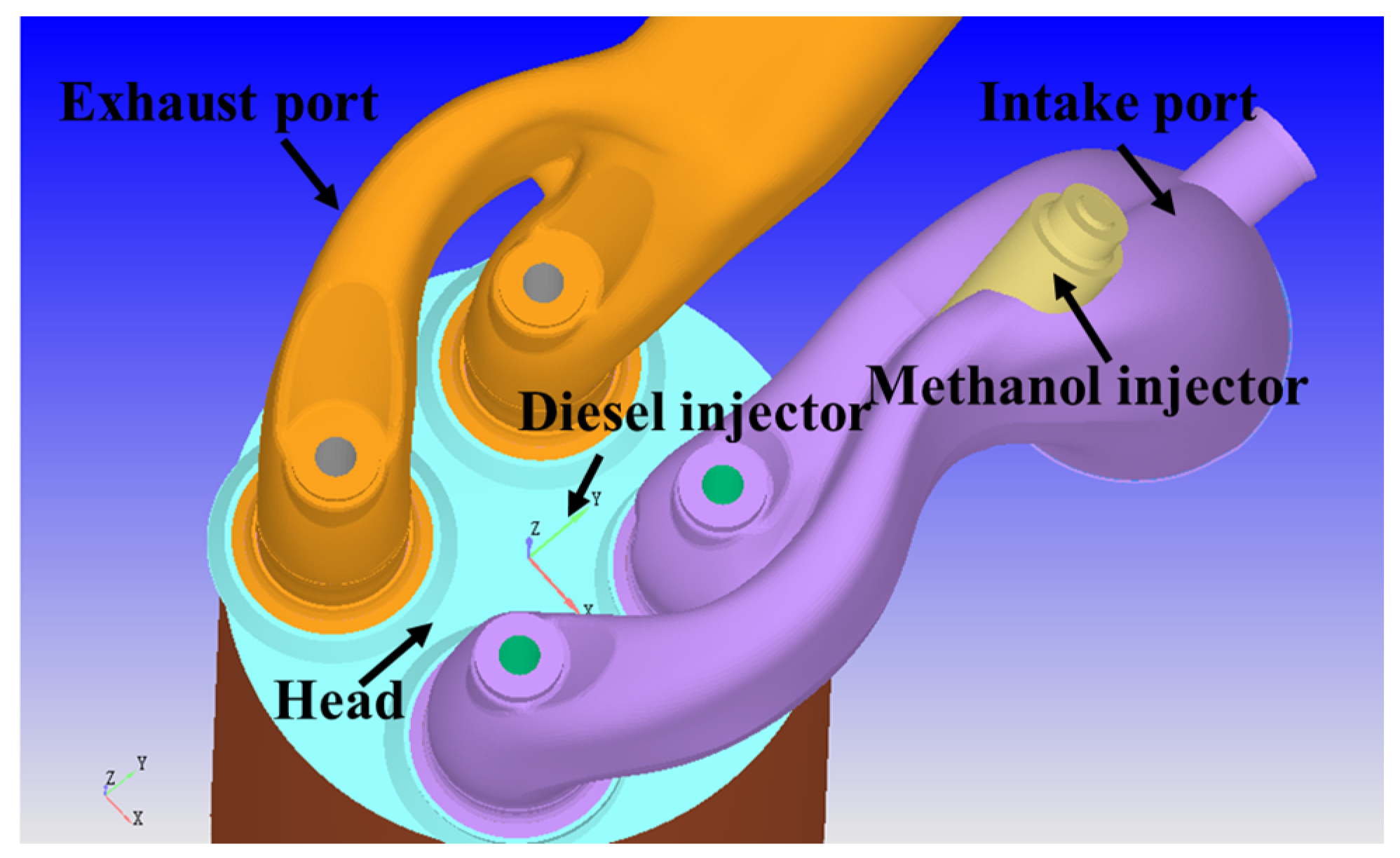
In the simulations, a diesel–methanol dual-fuel marine engine was used. The engine was a six-cylinder, four-stroke design. The geometric specification of the combustion chamber was 200 mm in bore, 300 mm in stroke, and 17:1 in compression ratio. The intake phasing ranged from −394 °CA after top dead center (ATDC) to −177 °CA ATDC, and the exhaust valve opened at 141 °CA ATDC and closed at 393 °CA ATDC. Figure 1 shows the physical model of the DMDF engine, which consists of an intake port, an exhaust port, and a combustion chamber. A methanol injector is installed at the intake port to inject methanol spray at low pressure, while a diesel injector is located at the cylinder head to introduce diesel. Table 1 provides the specifications of the test engine.
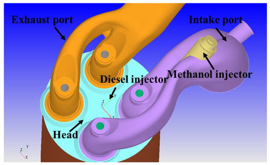
Figure 1.
Schematic of diesel–methanol dual-fuel engine model with intake and exhaust ports.

Table 1.
Specifications for the DMDF engine.
2.2. Numerical Models and Validations
The present study adopted a diesel–methanol dual-fuel engine model using the three-dimensional CFD software CONVERGE v2.4. To facilitate the combustion of diesel and methanol, a dual-fuel chemical mechanism was employed and integrated with the SAGE detailed chemical kinetics solver [30]. The n-heptane skeletal mechanism was derived from a newly developed detailed mechanism [31,32,33] from Lawrence Livermore National Laboratory, 7000 East Ave., Livermore, CA, USA. The methanol detailed mechanism was built based on the AramcoMech 3.0 mechanism [34]. The rate constant reported by Olm et al. [35] for the reaction CH2OH + O2= CH2O + HO2 was adopt to account for its significance in methanol oxidation. To predict medium-temperature auto-ignition, C7KET = C5H11CO + OH + CH2O and C5H11CO + O2 = NXC3H7 + C2H3 + CO + HO2 were selected to depict the decomposition of C7KET.
The renormalization group (RNG k − ε) model [36] was employed to predict the turbulence flow in the intake port, exhaust port, and cylinder. The wall heat transfer was simulated by the Angelberger model [37]. The spray droplet break-up process for diesel and methanol was formulated using the KH-RT model [38], while the spray–wall interaction was predicted using the wall film model [39]. The film mass was calculated using the film mass equations proposed by O’Rourke et al. [40]. Droplet evaporation and collision were predicted using the Frossling correlation [41] and the NTC model [42], respectively. Regarding emissions, the extended Zeldovich model [43] was employed for NOx formation and the Hiroyasu model [44] was used for soot prediction. In the simulations, a base grid of 4 mm was employed, with a three-level fixed embedding area added to refine the grid in diesel spray and methanol spray regions. Additionally, a three-level adaptive mesh refinement (AMR) based on velocity and temperature gradients was applied. A two-level AMR was also enabled during the intake and exhaust strokes.
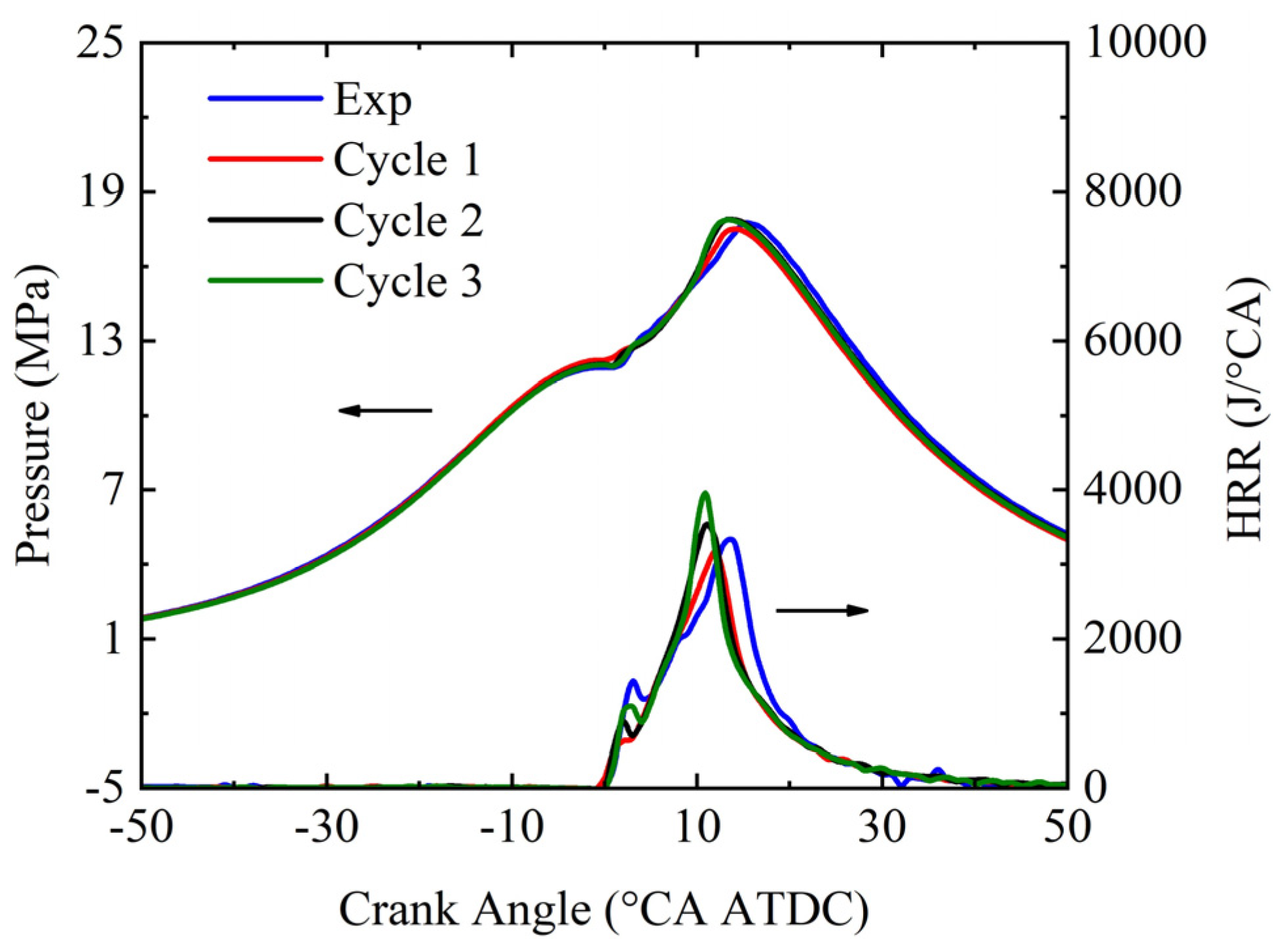
Before conducting multi-cycle engine simulations under varying methanol injection parameters, the engine model was validated against experimental results at a 75% engine load and an engine speed of 909 rpm. The temperatures of the intake valves, exhaust valves, and cylinder wall and cylinder head were 600 K, 780 K, and 500 K, respectively. Figure 2 depicts the comparisons between the numerical results and the experimental data. It shows that the simulation results of the second cycle closely match those of the third cycle, indicating that a two-cycle scheme effectively eliminates the influence of the initial conditions. Furthermore, the predicted in-cylinder pressure and heat release rate (HRR) align well with experimental results, highlighting the feasibility of the current model in predicting DMDF engine combustion.
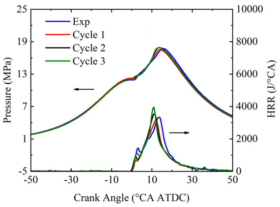
Figure 2.
Comparisons of in-cylinder pressure and heat release rate between simulation and experiment.
2.3. Operation Conditions
The parameters of methanol port injection significantly affect the atomization and evaporation of methanol spray droplets. Improving methanol atomization can enhance the quality of the methanol–air mixture, leading to more efficient combustion and lower pollution emissions. In the baseline engine, the injection pressure was 8 bar, with a nozzle diameter of 0.25 mm, and a start of injection (SOI) at −400 °CA ATDC. The methanol injection conditions used in this study are listed in Table 2. Injection pressures ranging from 8 bar to 50 bar were examined, while the injection duration remained fixed, with the SOI varying from −360 °CA ATDC to −440 °CA ATDC. With a constant flow rate of methanol, three different nozzle diameters (i.e., 0.2 mm, 0.25 mm, and 0.3 mm) for the methanol injector were investigated, which corresponded to the nozzle numbers of 46 holes, 30 holes, and 20 holes, respectively.
Table 2.
Parameters for methanol port injection.
3. Results and Discussion
3.1. Optimization of Engine Valve Phasing
The primary advantage of methanol port injection is its low retrofit cost. However, methanol injected into the intake port can be swept into the exhaust port during scavenging processes, leading to a significant decline in fuel economy at larger valve overlap angles. Therefore, optimizing valve phasing is essential for diesel engines operating in DMDF mode. The distributions of methanol during scavenging are illustrated in Figure 3. Herein, ∆θ = −6 °CA, ∆θ = 19 °CA, and ∆θ = 44 °CA correspond to −6 °CA, 19 °CA, and 44 °CA after intake valve opening, respectively. The red regions indicate regions where the methanol mass fraction exceeds 0.05. Before the intake valve opens, methanol–air mixtures accumulate in the intake port. Once the intake valve opens, methanol follows the scavenging flow into the exhaust port due to the incomplete closure of the exhaust valve, leading to methanol loss until the exhaust valve fully closes. At ∆θ = 44 °CA, a significant portion of the injected methanol is swept into the exhaust port under the original valve phasing, leaving only a small fraction available for combustion. With an optimized valve phasing, the volume of red regions within the cylinder increases significantly, while the red regions in the exhaust port shrink compared to the original valve phasing. This indicates that the optimized valve phasing improves retention of injected methanol within the cylinder and reduces scavenging mass losses. As a result, optimized valve phasing plays a crucial role in improving the indicated thermal efficiency (ITE) of DMDF engines.
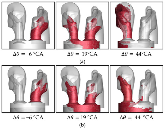
Figure 3.
Methanol distribution after scavenging starting. (a) Original and (b) optimized valve phasing (∆ represents the difference between the current time and the opening time of the intake valve).
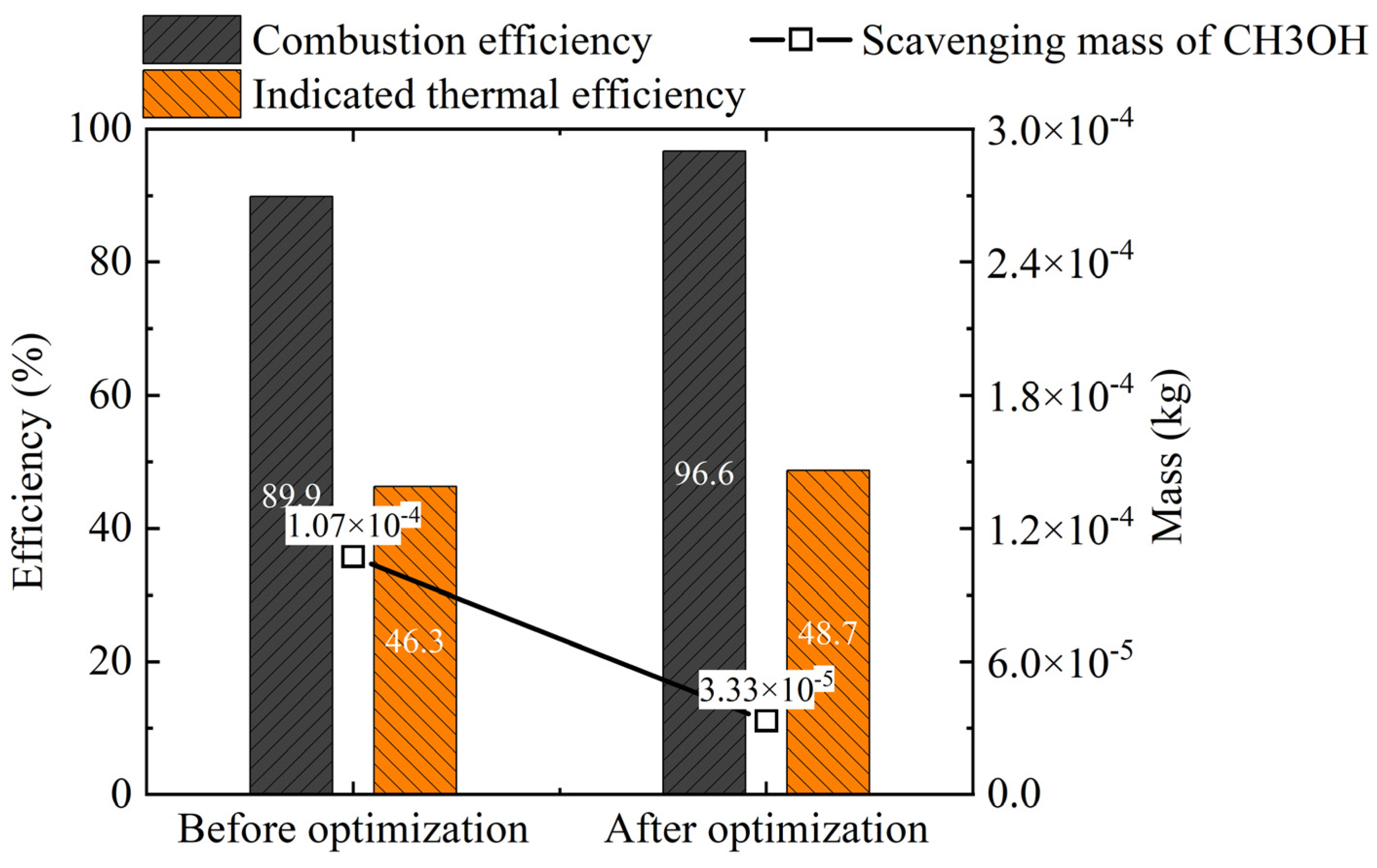
Figure 4 shows the comparisons of methanol scavenging mass, combustion efficiency, and indicated thermal efficiency. It shows that the scavenging mass of methanol decreased from 1.07 × 10⁻⁴ kg to 3.33 × 10⁻⁵ kg after optimizing the valve phasing, representing a reduction of approximately two-thirds. With increased participation of methanol in combustion, the combustion efficiency improved from 89.9% to 96.6%. Furthermore, the ITE increased from 46.3% to 48.7%. These results confirm that optimized valve phasing effectively minimizes methanol scavenging loss, reduces unburned methanol emissions, and enhances overall engine performance.
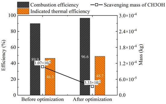
Figure 4.
Comparisons of methanol scavenging mass, combustion efficiency, and indicated thermal efficiency.
Figure 5 illustrates the combustion process and pollutant formation after optimizing valve phasing. It shows that the methanol–air mixture is uniformly distributed within the cylinder at 0 °CA. Starting from 2 °CA, compression ignition of diesel spray occurs, creating a high-temperature region that induces methanol–air mixture ignition. As a result, methanol consumption begins, leading to a reduction in its mass fraction. At 4 °CA, with the expansion of the high-temperature region caused by diesel spray development, further depletion of methanol takes place within the cylinder. By 6 °CA, both the high-temperature region and diesel spray occupy nearly all chamber while continuous consumption of methanol persists. During this stage, there is further contraction of high methanol concentration areas as the remaining quantities are consumed during subsequent combustion processes. Regarding the distributions of NOx and soot emissions, the gray and purple areas indicate iso-surfaces of NOx and a soot mass fraction of 0.004. At 8 °CA, a small amount of NOx and soot starts to emerge in the cylinder. By 10 °CA, both NOx and soot concentrations begin to increase, appearing in various areas of diesel spray combustion. Notably, NOx predominantly accumulates upstream of the combustion zone due to pre-mixed combustion with higher oxygen concentration facilitating its generation. Downstream from the region where oxygen concentration decreases significantly, a mixed-controlled combustion occurs, leading to substantial production of soot. From 10 °CA to 20 °CA, there is a rapid increase in both NOx and soot masses as combustion progresses intensively. The diesel injection ceases after 20 °CA, and the remaining diesel in the cylinder undergoes combustion by mixing with air. As the combustion rate decreases and the piston descends, there is a significant drop in temperature within the cylinder. At 30°CA, there is a decrease in soot quality due to competition between generation and oxidation rates. During the interval from 20 °CA to 30°CA, the oxidation rate becomes more prominent, resulting in a decline in soot quality.
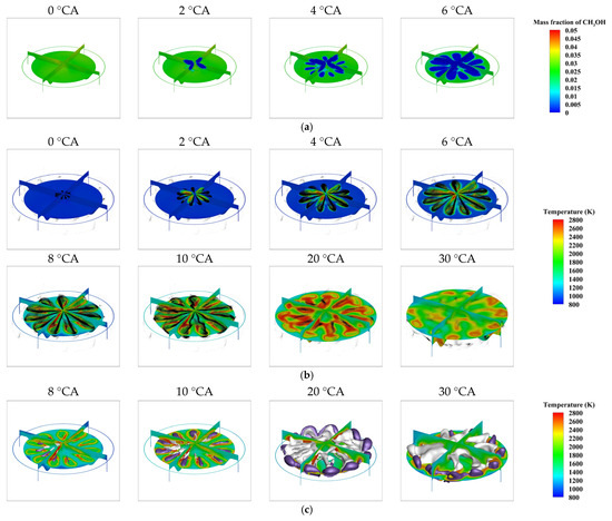
Figure 5.
Distribution of (a) methanol fraction, (b) temperature, and (c) NOx and soot emissions. The black particles represent diesel spray, and gray and purple colors represent the iso-surface of NOx and soot mass fraction at 0.004, respectively.
3.2. Effects of Injection Phasing on Engine Performance
Figure 6 shows the effects of injection phasing on the in-cylinder pressure, HRR, and combustion phase. As the SOI advances, the HRR phase is initially delayed and then advanced, while the peak value of HRR gradually increases. When SOI is −440 °CA, the HRR phase occurs earlier compared to other conditions, with a higher peak HRR. As shown in Figure 6b, CA90 initially increases and then decreases with SOI advancement, whereas CA10 and CA50 remain almost unchanged. Consequently, the combustion duration from CA10 to CA90 first increases and then decreases as SOI advances, reaching its shortest duration at SOI = −440 °CA, which is beneficial for improving engine performance. Figure 6c demonstrates how SOI influences methanol film formation and the amount of methanol available for combustion. As SOI advances, there is a gradual decrease in mass for methanol film while an increase occurs in the mass of methanol entering the cylinder. Notably, at SOI = −440 °CA, the maximum quantity of methanol is retained within the cylinder, enhancing combustion efficiency.
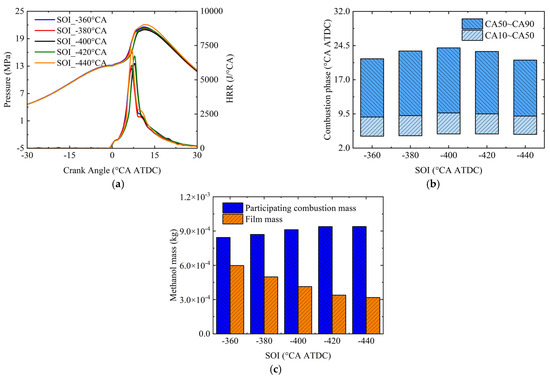
Figure 6.
Effects of injection phasing on (a) in-cylinder pressure and heat release rate, (b) combustion phase, and (c) methanol mass.
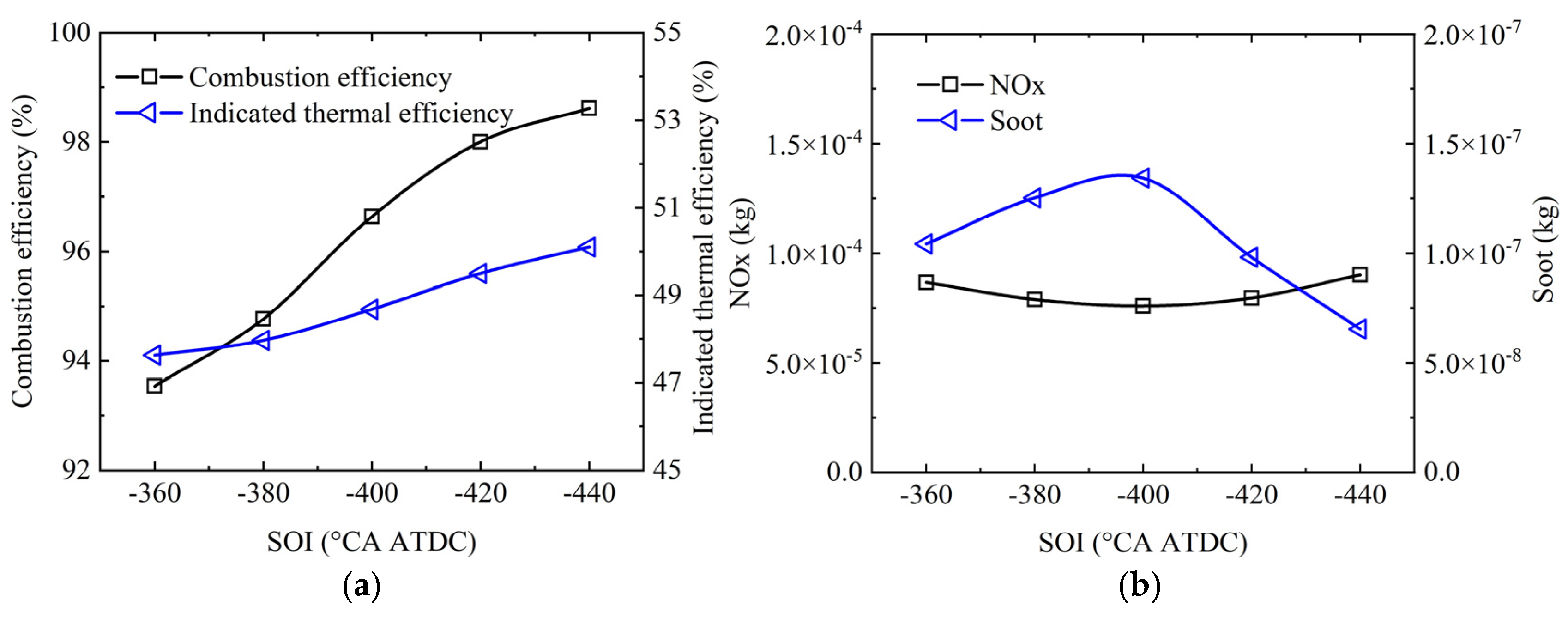
Figure 7 shows the effects of injection phasing on engine combustion efficiency, ITE, and pollutant emissions. Pollutant emissions refer to the number of emissions produced per cycle by each cylinder of engine. It is seen that advancing the SOI leads to a gradual increase in engine combustion efficiency and improved fuel combustion, resulting in an increased release of combustion heat and enhanced ITE. For the DMDF engine, the combustion heat release comprises both methanol and diesel combustion heat releases. Since direct injection of diesel results in a little unburned diesel, the increase in combustion efficiency can be attributed to the greater mass of methanol involved in cylinder combustion, increasing the engine’s overall total combustion heat release. Figure 7b demonstrates that NOx emissions gradually increase while soot emissions decrease with advanced SOI, indicating a trade-off relationship between these two pollutants.
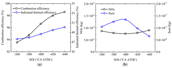
Figure 7.
Effects of injection phasing on (a) combustion efficiency and indicated thermal efficiency and (b) NOx and soot emissions.
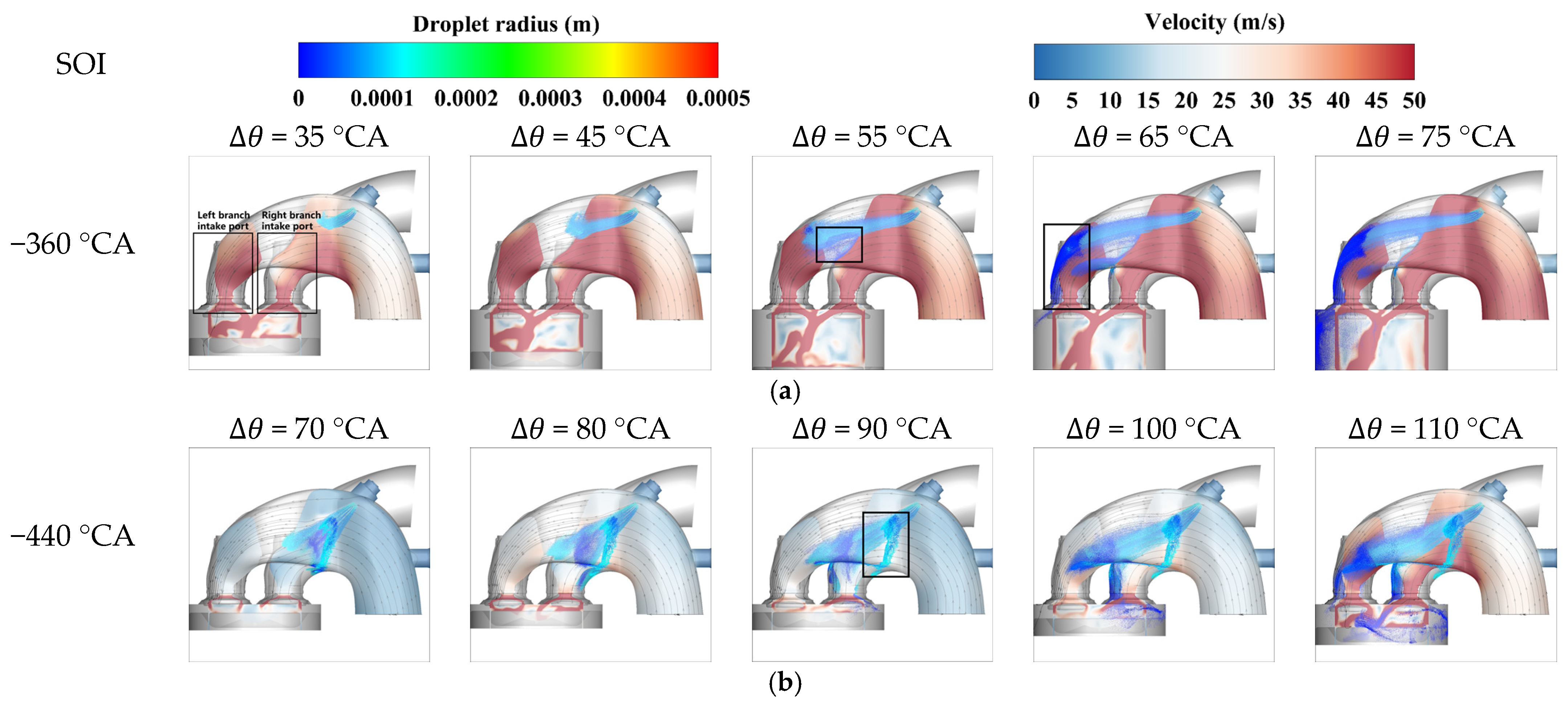
Figure 8a shows the methanol intake port injection from ∆θ = 35 °CA (35 °CA after start of injection) to ∆θ = 75 °CA (75 °CA after start of injection) with an SOI of −360 °CA. The slice cloud diagram represents the velocity field, the color of the methanol spray droplets indicates the spray droplet size, and the solid black line depicts the flow field streamlines. At ∆θ = 35 °CA, methanol is injected along the axis by a low-pressure injector in the intake port and starts to rise under intake flow influence. The penetration distance and spray area of methanol spray gradually increase as the injection progresses. At ∆θ = 55 °CA, methanol spray collides with the intake port wall, resulting in a small amount of film formation at the collision site (as shown in the black box). As the injection continues, methanol droplets collide with left branch intake port wall under strong intake airflow, leading to significant accumulation of wall film (as shown in black box at ∆θ = 65 °CA).
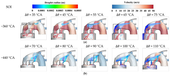
Figure 8.
Distribution of flow line and spray droplets for methanol intake port injection at (a) SOI = −360 °CA and (b) SOI = −440 °CA. The slice cloud represents the velocity field, and the color of spray droplets represents the droplet size, and solid black line represents the flow line.
Figure 8b illustrates the methanol intake port injection process from ∆θ = 70 °CA (70 °CA after start of injection) to ∆θ = 110 °CA (110 °CA after start of injection) with a SOI of −440 °CA. At ∆θ = 70 °CA, due to weak airflow movement within the intake port, methanol spray develops along the axis direction. At ∆θ = 90 °CA, the methanol spray encounters the intake port wall, causing formation of a small amount of film (as shown in the black box). At ∆θ = 100 °CA, the methanol spray divides into two streams at the airway forks: one enters the cylinder through the right branch airway while the other enters through the left branch airway at ∆θ = 110 °CA. Accordingly, the development analysis from the initial spraying stage until entry into the cylinder was conducted for both SOI = −360 °CA and SOI = −440 °CA. The results indicate that at SOI = −360 °CA, the vigorous air motion causes the methanol spray to impinge on the wall of the left branch intake port, resulting in a substantial formation of film. By contrast, at SOI = −440 °CA, the airflow movement is relatively weak, preventing the spray from being carried towards the wall by the air flow. This elucidates why advancing SOI leads to a reduction in methanol film mass and an increase in methanol mass participating combustion.
3.3. Effects of Injection Pressure on Engine Performance
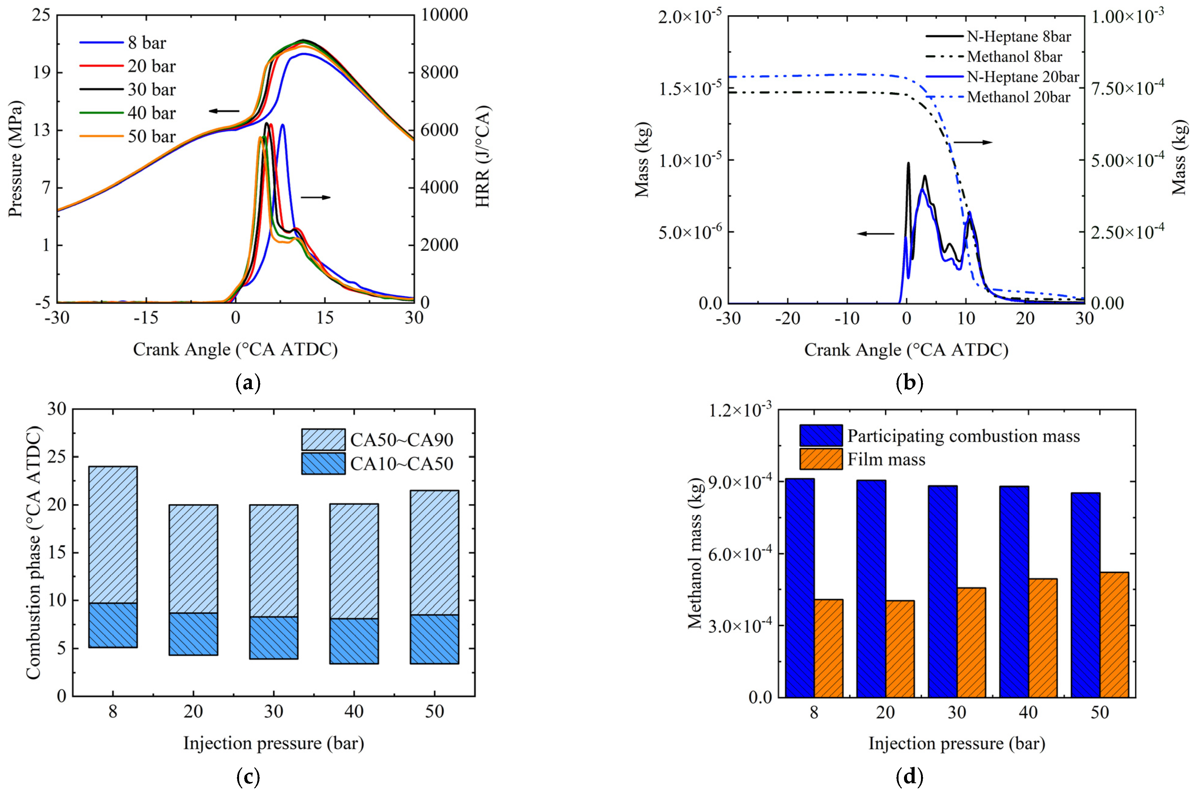
Figure 9a shows the effects of injection pressure on the pressure, HRR, and combustion phase of the engine. As the injection pressure increases, both the HRR and the cylinder pressure phases advance. The HRR phases at injection pressures of 20 bar, 30 bar, 40 bar, and 50 bar occur significantly earlier than at 8 bar. Additionally, the HRR exhibits two peaks, and cylinder pressure is significantly increased. This phenomenon is attributed to simultaneous consumption of methanol and diesel at 8 bar injection pressure. At 20 bar injection pressure, after the methanol is consumed, diesel still remains in the cylinder, as shown in Figure 9b. Consequently, diesel fuel undergoes diffusion combustion, producing a second HRR peak. With increasing injection pressure, the combustion start time CA10 advances while the combustion end time CA90 initially decreases and then increases, as depicted in Figure 9c. The shortest combustion duration occurs at 20 bar, which promotes improved engine performance. Figure 9d illustrates variations in methanol mass participating combustion and film mass at different injection pressures. There is an increase in methanol film mass and decrease in methanol mass participating combustion with elevated injection pressure. Further analysis regarding how injection pressures affect film mass will be provided later.
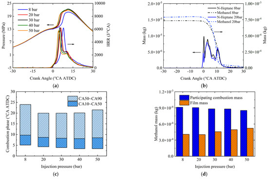
Figure 9.
Effects of injection pressure on (a) in-cylinder pressure and heat release rate, (b) changes of diesel and methanol mass, (c) combustion phase, and (d) methanol mass.
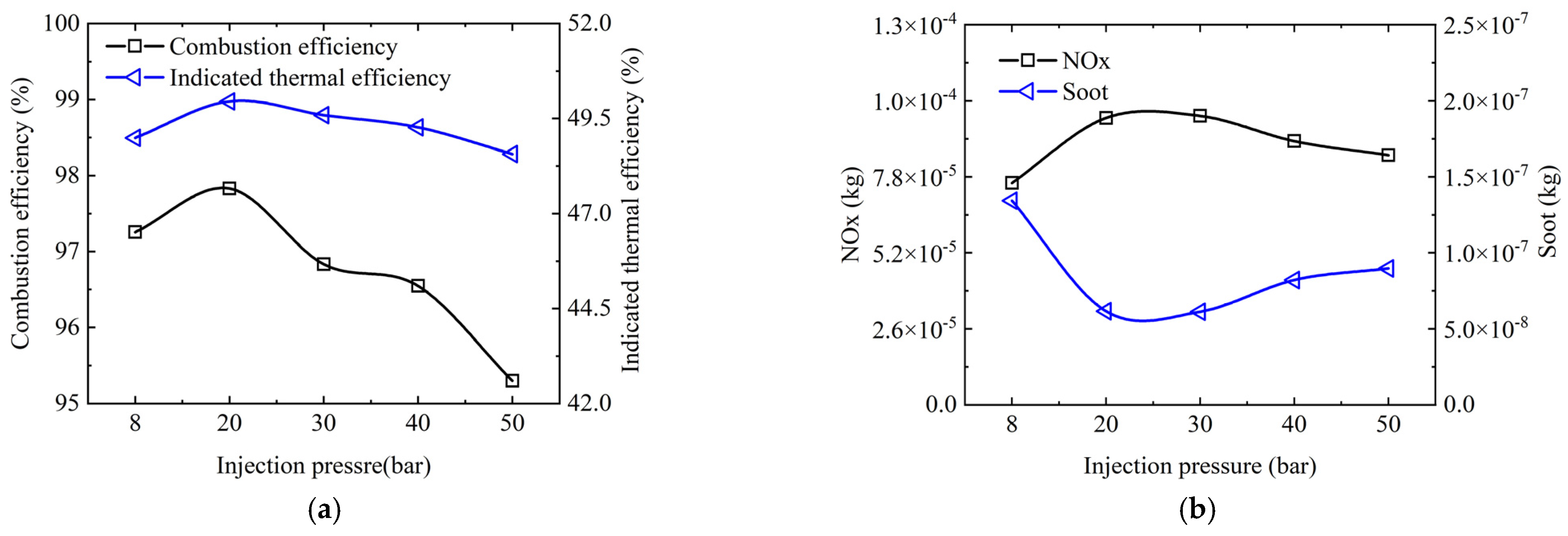
Figure 10 shows the effects of injection pressure on engine combustion efficiency, ITE, and pollutant emissions. It is seen that as the injection pressure increases, the combustion efficiency of the engine improves due to an increase in methanol mass participating combustion, resulting in higher engine ITE. The highest ITE is achieved at 20 bar injection pressure. NOx emissions initially increase and then decrease with increasing injection pressure, while soot emissions exhibit a reverse trend, indicating a trade-off relationship between these two pollutants. These observations can be attributed to the shorter combustion durations, which lead to more concentrated heat release and higher temperatures within the cylinder.

Figure 10.
Effects of injection pressure on (a) combustion efficiency and indicated thermal efficiency, and (b) NOx and soot emissions.
Figure 11 shows the methanol injections from ∆θ = 30 °CA (30° CA after the start of injection) to ∆θ = 70 °CA (70° CA after the start of injection) at 20 bar and 50 bar injection pressures. The methanol spray is injected along the axis at ∆θ = 30 °CA. The collision between the spray and the intake port results in film formation (as indicated by the black box at ∆θ = 40 °CA). With further development of the spray, it bifurcates into two streams, forming additional films on both bifurcated walls. These two streams of spray enter the cylinder through their respective left and right branches. Due to the enhanced airflow movement at ∆θ = 70 °CA, methanol film is formed on the wall as a result of the collision between the intake air movement at the branch airway and the wall (as indicated by the black box). The spray area, as depicted in Figure 11b, exhibits an increase when the injection pressure reaches 50 bar due to the higher flow rate of the injector. Consequently, there is a corresponding rise in both the collision between the spray and the wall and the film formation on various surfaces such as the intake port side wall, the intake port bifurcation, and the left branch wall at ∆θ = 30 °CA, ∆θ = 40 °CA, and ∆θ = 60 °CA, respectively. There are two factors contributing to this phenomenon: firstly, the expansion of spray area results in an increase in both spray and wall impact areas; secondly, the elevation of injection pressure leads to a reduction in droplet size, rendering these smaller droplets more susceptible to the influence of intake flow. These two factors collectively contribute to a higher occurrence of film formation at an injection pressure of 50 bar compared to 20 bar.
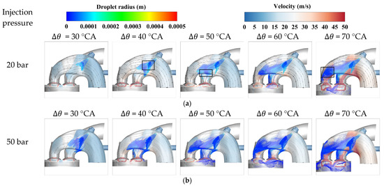
Figure 11.
Distribution of flow line and spray droplets for methanol intake port injection at (a) injection pressure = 20 bar and (b) injection pressure = 50 bar. The slice cloud represents the velocity field, the color of the spray droplets represents the droplet size, and the solid black line represents the flow line.
3.4. Effects of Nozzle Diameter on Engine Performance
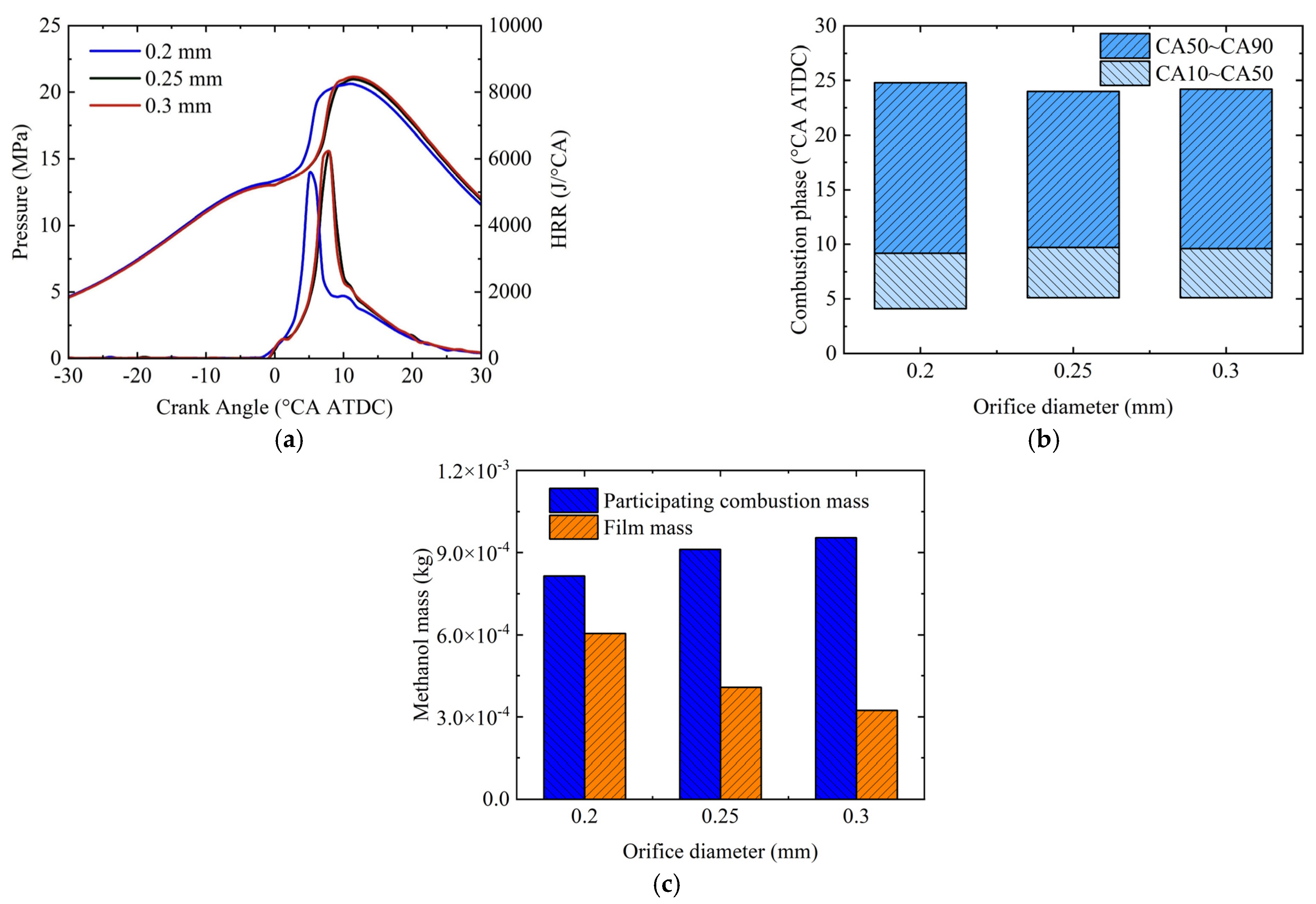
Figure 12 shows the effects of nozzle diameter on the in-cylinder pressure, HRR, and combustion phase of engine. When the nozzle diameter is 0.2 mm, both the HRR and cylinder pressure phases advance, leading to lower peak values. Analysis of the combustion phase reveals that CA10 occurs earlier than in the other two operating conditions, while CA90 occurs later with a 0.2 mm nozzle diameter. Consequently, the combustion duration is longer compared to the other operating conditions. Regarding film mass, it shows that as the nozzle diameter increases, there is a decrease in methanol film mass but an increase in methanol mass participating combustion within the cylinder. This suggests that larger nozzle diameters facilitate greater methanol combustion within the cylinder.

Figure 12.
Effects of nozzle diameter on (a) in-cylinder pressure and heat release rate, (b) combustion phase, and (c) methanol mass participating combustion and film mass.
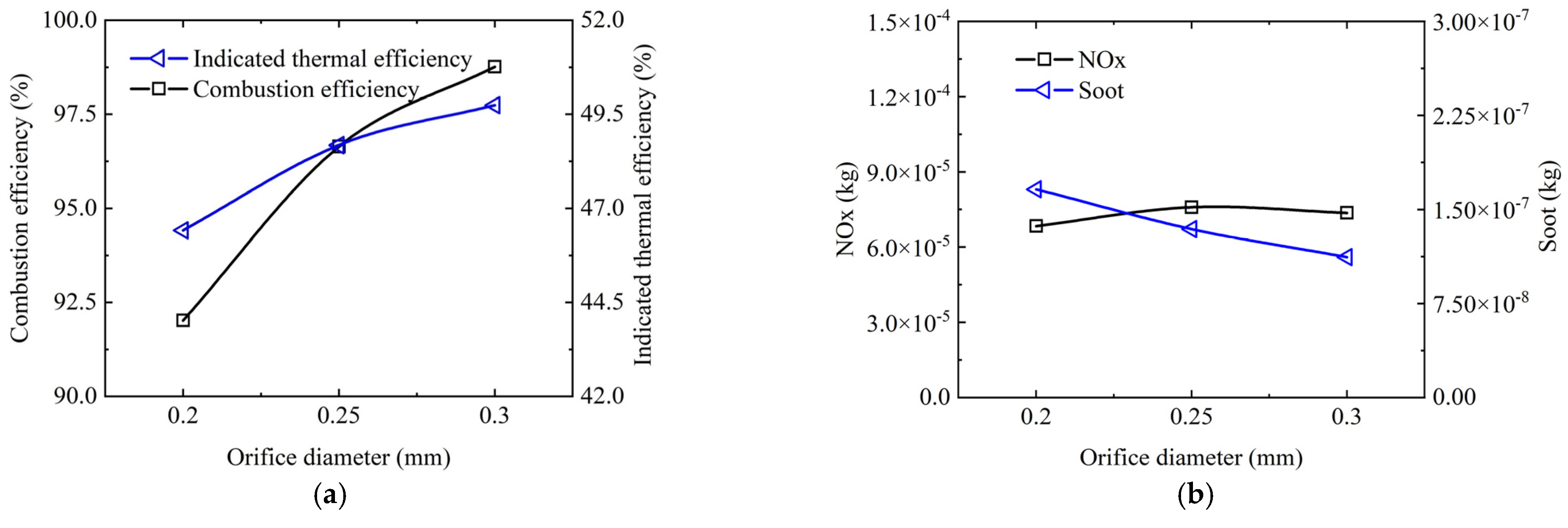
Figure 13 shows the effects of nozzle diameter on engine combustion efficiency, ITE, and pollutant emissions. As the nozzle diameter increases, methanol mass participating combustion also increases, leading to improved engine combustion efficiency. Additionally, compared to a 0.2 mm nozzle diameter, both 0.25 mm and 0.3 mm diameters exhibit shorter combustion durations and higher heat release rates. Consequently, under their combined effect, the ITE gradually increases with increasing nozzle diameter. Additionally, as shown in Figure 13b, soot emissions decrease progressively with increasing nozzle diameter. However, NOx emissions for both 0.25 mm and 0.3 mm diameters are higher than those for a 0.2 mm diameter. The possible reason is that the combustion heat release is higher when the nozzle diameter is 0.25 mm and 0.3 mm, which leads to an increased in-cylinder temperature, promoting the generation of NOx while simultaneously inhibiting soot formation.
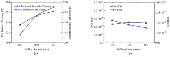
Figure 13.
Effects of nozzle diameter on (a) combustion efficiency and indicated thermal efficiency, and (b) NOx and soot emissions.
Figure 14 resents the methanol intake port injection from ∆θ = 50 °CA to ∆θ = 90 °CA with different nozzle diameters. At ∆θ = 50 °CA, the methanol spray develops along a central axis. At ∆θ = 60 °CA, the methanol spray collides with the intake port side wall, resulting in a small amount of film formation. There is no significant difference observed between the droplet size of sprays with 0.2 mm and 0.3 mm nozzle diameters at ∆θ = 60 °CA. At ∆θ = 70 °CA, due to intensive airflow movement within the intake port, smaller droplets at the front of sprays with a nozzle diameter of 0.2 mm are stripped off while there is a significantly lower number of small droplets produced by a 0.3 mm nozzle diameter. At ∆θ = 80 °CA, the spray divides into two streams and enters the cylinder through two branches. At ∆θ = 90 °CA, there is a more noticeable difference in small droplet numbers between these two conditions. This can be attributed to smaller sizes of droplets generated by a 0.2 mm nozzle diameter compared to those generated by a 0.3 mm nozzle diameter under similar conditions. Consequently, these smaller droplets have less mass and are more likely to be carried by airflow and impact on walls during movement, resulting in film formation. Although reducing the nozzle diameter results in more uniform spray droplets, which enhance mixture formation, a smaller nozzle diameter strengthens the tendency for film formation, thereby compromising methanol mass participating combustion and undermining engine combustion efficiency.
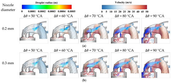
Figure 14.
Distribution of flow line and spray droplets for methanol intake port injection at (a) nozzle diameter = 0.2 mm and (b) nozzle diameter = 0.3 mm. The slice cloud represents the velocity field, the color of the spray droplets represents the droplet size, and the solid black line represents the flow line.
4. Conclusions
In the present study, a diesel–methanol dual-fuel engine model was numerically investigated, focusing on combustion and emissions characteristics. Multi-cycle simulations incorporating diesel and methanol dual-fuel chemical mechanisms were conducted to explore engine performance under various key parameters, including valve phasing, injection pressure, injection phasing, and nozzle diameter. The correlations between methanol film mass, thermal efficiency, and pollutants were clarified.
The indicated thermal efficiency of a diesel–methanol dual-fuel engine is substantially affected by the methanol combustion efficiency. Optimizing injection parameters can minimize methanol film formation, thereby enhancing the methanol mass available for combustion. Advancing injection timing and increasing nozzle diameter reduce methanol film formation. An optimal injection pressure of 20 bar minimizes film mass and achieves optimized engine performance.
Advancing injection timing and increasing nozzle diameter have a detrimental effect on the film mass. The reasons are ascribed to an early injection timing, which results in a portion of methanol being sprayed into the intake before the intake valve opens, preventing methanol from being carried by airflow to the intake wall. Additionally, a larger nozzle diameter results in larger spray droplet size, enhancing resistance against entrainment by airflow and diminishing film mass. Conversely, a higher injection pressure leads to increased methanol film formation due to an increased spray impact area and smaller droplet sizes, which results in methanol film mass.
Optimizing the valve phasing significantly reduces methanol scavenging mass loss by approximately two-thirds, resulting in an increase in the indicated thermal efficiency from 46.3% to 48.7%. Additionally, as most of the methanol gets consumed, NOx and soot formation occur around the diesel spray region. The upstream of the spray exhibits NOx formation while higher concentrations of soot are observed downstream.
The present study focusses on investigating the impact of valve phasing and key injection parameters on the combustion and emissions characteristics of DMDF engines in open valve injection mode. Further investigation is required to explore the influence of methanol injection in closed valve injection mode on the performance of DMDF engines.
Author Contributions
Conceptualization, Z.L., J.M. and J.P.; Software, Z.S.; Investigation, Z.S., Z.L., J.M., C.W. and W.L.; Data curation, Z.S.; Writing—review & editing, Z.S. and J.P.; Visualization, Z.S., C.W., W.L. and J.P.; Supervision, J.P.; Funding acquisition, J.P. All authors have read and agreed to the published version of the manuscript.
Funding
This work was supported by the National Natural Science Foundation of China (52222604) and the Science Foundation of Shandong Province of China (ZR2023ZD20).
Data Availability Statement
The original contributions presented in this study are included in the article. Further inquiries can be directed to the corresponding authors.
Conflicts of Interest
Authors Zhenyu Sun, Jinchun Ma, Chunying Wang, Wei Li and Jiaying Pan were employed by the company Weichai Power Co., Ltd. The remaining authors declare that the research was conducted in the absence of any commercial or financial relationships that could be construed as a potential conflict of interest. The company had no role in the design of the study; in the collection, analyses, or interpretation of data; in the writing of the manuscript, or in the decision to publish the results.
Abbreviations
ATDC, after top dead center; AMR, adaptive mesh refinement; DMDF, diesel–methanol dual-fuel; EGR, exhaust gas recirculation; HRR, heat release rate; ITE, indicated thermal efficiency; RNG, renormalization group; SOI, start of injection.
References
- Lian, Z.; Li, W.; Cai, Y.; Chen, H.; Jiang, J.; Li, G.; Zhao, F.; Yu, W. Investigations of diesel and natural gas injection interaction on combustion characteristics of a high-pressure direct-injection dual-fuel engine based on large eddy simulation. Appl. Energy 2025, 378, 124807. [Google Scholar] [CrossRef]
- Zhao, W.; Li, Z.; Huang, G.; Zhang, Y.; Qian, Y.; Lu, X. Experimental investigation of direct injection dual fuel of n-butanol and biodiesel on Intelligent Charge Compression Ignition (ICCI) Combustion mode. Appl. Energy 2020, 266, 114884. [Google Scholar] [CrossRef]
- Gong, C.; Li, Z.; Sun, J.; Liu, F. Evaluation on combustion and lean-burn limit of a medium compression ratio hydrogen/methanol dual-injection spark-ignition engine under methanol late-injection. Appl. Energy 2020, 277, 115622. [Google Scholar] [CrossRef]
- Wang, X.; Gao, J.; Chen, Z.; Chen, H.; Zhao, Y.; Huang, Y.; Chen, Z. Evaluation of hydrous ethanol as a fuel for internal combustion engines: A review. Renew. Energy 2022, 194, 504–525. [Google Scholar] [CrossRef]
- Verhelst, S.; Turner, J.W.G.; Sileghem, L.; Vancoillie, J. Methanol as a fuel for internal combustion engines. Prog. Energy Combust. Sci. 2019, 70, 43–88. [Google Scholar] [CrossRef]
- Su, L.-W.; Li, X.-R.; Sun, Z.-Y. The consumption, production and transportation of methanol in China: A review. Energy Policy 2013, 63, 130–138. [Google Scholar] [CrossRef]
- Huang, Z.; Lu, H.; Jiang, D.; Zeng, K.; Liu, B.; Zhang, J.; Wang, X. Engine performance and emissions of a compression ignition engine operating on the diesel-methanol blends. Proc. Inst. Mech. Eng. Part D J. Automob. Eng. 2004, 218, 435–447. [Google Scholar] [CrossRef]
- Udayakumar, R.; Sundaram, S.; Sivakumar, K. Engine performance and exhaust characteristics of dual fuel operation in DI diesel engine with methanol. In SAE Technical Paper; SAE International: Warrendale, PA, USA, 2004; ISSN 0148-7191. [Google Scholar]
- Tian, Z.; Wang, Y.; Zhen, X.; Liu, Z. The effect of methanol production and application in internal combustion engines on emissions in the context of carbon neutrality: A review. Fuel 2022, 320, 123902. [Google Scholar] [CrossRef]
- Jin, C.; Ding, C.; Hu, J.; Geng, Z.; Li, X.; Dong, J.; Xu, T.; Liu, H. Study on the stability and properties of carbon neutral methanol in blends with diesel fuel. Fuel 2024, 374, 132453. [Google Scholar] [CrossRef]
- Song, R.; Liu, J.; Wang, L.; Liu, S. Performance and Emissions of a Diesel Engine Fuelled with Methanol. Energy Fuels 2008, 22, 3883–3888. [Google Scholar] [CrossRef]
- Wang, Q.; Wei, L.; Pan, W.; Yao, C. Investigation of operating range in a methanol fumigated diesel engine. Fuel 2015, 140, 164–170. [Google Scholar] [CrossRef]
- Agarwal, A.K.; Kumar, V.; Jena, A.; Kalwar, A. Fuel injection strategy optimisation and experimental performance and emissions evaluation of diesel displacement by port fuel injected methanol in a retrofitted mid-size genset engine prototype. Energy 2022, 248, 123593. [Google Scholar] [CrossRef]
- Wei, L.; Yao, C.; Han, G.; Pan, W. Effects of methanol to diesel ratio and diesel injection timing on combustion, performance and emissions of a methanol port premixed diesel engine. Energy 2016, 95, 223–232. [Google Scholar] [CrossRef]
- Karvounis, P.; Theotokatos, G.; Patil, C.; Xiang, L.; Ding, Y. Parametric investigation of diesel–methanol dual fuel marine engines with port and direct injection. Fuel 2025, 381, 133441. [Google Scholar] [CrossRef]
- Zang, R.; Yao, C. Numerical Study of Combustion and Emission Characteristics of a Diesel/Methanol Dual Fuel (DMDF) Engine. Energy Fuels 2015, 29, 3963–3971. [Google Scholar] [CrossRef]
- Liu, J.; Yao, A.; Yao, C. Effects of injection timing on performance and emissions of a HD diesel engine with DMCC. Fuel 2014, 134, 107–113. [Google Scholar] [CrossRef]
- Altun, Ş.; Fırat, M.; Varol, Y.; Okcu, M. Comparison of direct and port injection of methanol in a RCCI engine using diesel and biodiesel as high reactivity fuels. Process Saf. Environ. Prot. 2023, 174, 681–693. [Google Scholar] [CrossRef]
- Panda, K.; Ramesh, A. Parametric investigations to establish the potential of methanol based RCCI engine and comparison with the conventional dual fuel mode. Fuel 2022, 308, 122025. [Google Scholar] [CrossRef]
- Qu, G.; Yao, A.; Chen, C.; Ren, J.; Yao, C. Effect of EGR strategy on combustion and emission of DMDF engine for meeting China VI emission legislation. Fuel 2021, 299, 120879. [Google Scholar] [CrossRef]
- Wang, J.; Chen, L.; Chen, J. Experimental investigation on combustion and emission characteristics of diesel methanol dual fuel (DMDF) engine at various altitudes. Energy Environ. 2024, 35, 331–352. [Google Scholar] [CrossRef]
- Kumar, D.; Sonawane, U.; Chandra, K.; Agarwal, A.K. Experimental investigations of methanol fumigation via port fuel injection in preheated intake air in a single cylinder dual-fuel diesel engine. Fuel 2022, 324, 124340. [Google Scholar] [CrossRef]
- Wang, Q.; Yao, C.; Dou, Z.; Wang, B.; Wu, T. Effect of intake pre-heating and injection timing on combustion and emission characteristics of a methanol fumigated diesel engine at part load. Fuel 2015, 159, 796–802. [Google Scholar] [CrossRef]
- Guan, W.; Wang, X.; Zhao, H.; Liu, H. Exploring the high load potential of diesel–methanol dual-fuel operation with Miller cycle, exhaust gas recirculation, and intake air cooling on a heavy-duty diesel engine. Int. J. Engine Res. 2021, 22, 2318–2336. [Google Scholar] [CrossRef]
- Chen, Z.; Yao, C.; Wang, Q.; Han, G.; Dou, Z.; Wei, H.; Wang, B.; Liu, M.; Wu, T. Study of cylinder-to-cylinder variation in a diesel engine fueled with diesel/methanol dual fuel. Fuel 2016, 170, 67–76. [Google Scholar] [CrossRef]
- Wei, F.; Zhang, Z.; Wei, W.; Zhang, H.; Cai, W.; Dong, D.; Li, G. Multi-objective optimization of the performance for a marine methanol-diesel dual-fuel engine. Fuel 2024, 368, 131556. [Google Scholar] [CrossRef]
- Dierickx, J.; Verbiest, J.; Janvier, T.; Peeters, J.; Sileghem, L.; Verhelst, S. Retrofitting a high-speed marine engine to dual-fuel methanol-diesel operation: A comparison of multiple and single point methanol port injection. Fuel Commun. 2021, 7, 100010. [Google Scholar] [CrossRef]
- Xu, G.; García, A.; Jia, M.; Monsalve-Serrano, J. Computational optimization of the piston bowl geometry for the different combustion regimes of the dual-mode dual-fuel (DMDF) concept through an improved genetic algorithm. Energy Convers. Manag. 2021, 246, 114658. [Google Scholar] [CrossRef]
- Li, Y.; Chen, H.; Zhang, C.; Chen, H. Effects of diesel pre-injection on the combustion and emission characteristics of a common-rail diesel engine fueled with diesel-methanol dual-fuel. Fuel 2021, 290, 119824. [Google Scholar] [CrossRef]
- Senecal, P.; Pomraning, E.; Richards, K.; Briggs, T.; Choi, C.; McDavid, R.; Patterson, M. Multi-dimensional modeling of direct-injection diesel spray liquid length and flame lift-off length using CFD and parallel detailed chemistry. SAE Trans. 2003, 112, 1331–1351. [Google Scholar]
- Mehl, M.; Pitz, W.J.; Westbrook, C.K.; Curran, H.J. Kinetic modeling of gasoline surrogate components and mixtures under engine conditions. Proc. Combust. Inst. 2011, 33, 193–200. [Google Scholar] [CrossRef]
- Mehl, M.; Pitz, W.J.; Sjöberg, M.; Dec, J.E. Detailed Kinetic Modeling of Low-Temperature Heat Release for PRF Fuels in an HCCI Engine. In SAE Technical Paper; SAE International: Warrendale, PA, USA, 2009. [Google Scholar] [CrossRef]
- Curran, H.J.; Gaffuri, P.; Pitz, W.J.; Westbrook, C.K. A Comprehensive Modeling Study of n-Heptane Oxidation. Combust. Flame 1998, 114, 149–177. [Google Scholar] [CrossRef]
- Zhou, C.-W.; Li, Y.; Burke, U.; Banyon, C.; Somers, K.P.; Ding, S.; Khan, S.; Hargis, J.W.; Sikes, T.; Mathieu, O.; et al. An experimental and chemical kinetic modeling study of 1,3-butadiene combustion: Ignition delay time and laminar flame speed measurements. Combust. Flame 2018, 197, 423–438. [Google Scholar] [CrossRef]
- Olm, C.; Varga, T.; Valkó, É.; Curran, H.J.; Turányi, T. Uncertainty quantification of a newly optimized methanol and formaldehyde combustion mechanism. Combust. Flame 2017, 186, 45–64. [Google Scholar] [CrossRef]
- Han, Z.; Reitz, R.D. Turbulence Modeling of Internal Combustion Engines Using RNG κ-ε Models. Combust. Sci. Technol. 1995, 106, 267–295. [Google Scholar] [CrossRef]
- Angelberger, C.; Poinsot, T.; Delhay, B. Improving Near-Wall Combustion and Wall Heat Transfer Modeling in SI Engine Computations. In SAE Technical Paper; SAE International: Warrendale, PA, USA, 1997. [Google Scholar] [CrossRef]
- Beale, J.C.; Reitz, R.D. Modeling spray atomization with the Kelvin-Helmholtz/Rayleigh-Taylor hybrid model. At. Sprays 1999, 9, 623–650. [Google Scholar]
- O’Rourke, P.J.; Amsden, A. A spray/wall interaction submodel for the KIVA-3 wall film model. SAE Trans. 2000, 109, 281–298. [Google Scholar]
- O’rourke, P.; Amsden, A. A particle numerical model for wall film dynamics in port-injected engines. SAE Trans. 1996, 105, 2000–2013. [Google Scholar]
- Reitz, R.; Bracco, F. Mechanism of atomization of a liquid jet. Phys. Fluids 1982, 25, 1730–1742. [Google Scholar] [CrossRef]
- Taskiran, O.O.; Ergeneman, M. Trajectory based droplet collision model for spray modeling. Fuel 2014, 115, 896–900. [Google Scholar] [CrossRef]
- Heywood, J.B. Internal Combustion Engine Fundamentals, 1st ed.; McGraw-Hill Education: Columbus, OH, USA, 1988; Volume 25, pp. 1117–1128. [Google Scholar]
- Hiroyasu, H.; Kadota, T. Models for combustion and formation of nitric oxide and soot in direct injection diesel engines. SAE Trans. 1976, 85, 513–526. [Google Scholar]


Disclaimer/Publisher’s Note: The statements, opinions and data contained in all publications are solely those of the individual author(s) and contributor(s) and not of MDPI and/or the editor(s). MDPI and/or the editor(s) disclaim responsibility for any injury to people or property resulting from any ideas, methods, instructions or products referred to in the content. |
© 2025 by the authors. Licensee MDPI, Basel, Switzerland. This article is an open access article distributed under the terms and conditions of the Creative Commons Attribution (CC BY) license (https://creativecommons.org/licenses/by/4.0/).