Abstract
This critical review evaluates chemical looping combustion using a syngas derived from gasified biomass (BMD Syngas). It is anticipated that establishing such a process will open new opportunities for CO2 sequestration and the use of highly concentrated CO2 in the manufacturing and synthesis of fuels from entirely renewable feedstocks. This review focuses on the process conducted through using two interconnected fluidized bed units: a nickel oxide reduction unit (an endothermic Fuel Reactor) and a nickel oxidation unit (an exothermic Air Reactor). In this respect, a high-performance OC (HPOC) with Ni on a γ-Al2O3 fluidizable support (20wt% Ni, 1wt% Co, 5wt% La/γ-Al2O3) was developed at the CREC (Chemical Reactor Engineering Centre) of the University of Western Ontario, Canada. The HPOC was studied in a CREC Riser Simulator. The benefits of this mini-fluidized unit are that it can be operated at 2–40 s reaction times, 550–650 °C temperatures, 1.3–2.5 H2/CO ratios, and 0.5–1 biomass/syngas stoichiometric ratios, mimicking the conditions of industrial-scale CLC units. When using a syngas derived from biomass and the HPOC under these operating conditions, 90% CO, 92% H2, and 88% CH4 conversions, together with a 91% CO2 yield, were obtained. These results allowed the prediction of a 1.84–3.0 wt% () oxygen transport capacity, with a 40–70% nickel oxide conversion. The experimental data acquired with the CREC Riser Simulator permitted the development of realistic kinetic models. The resulting kinetics were used in combination with Computational Particle Fluid Dynamics (CPFD) to demonstrate the operability of a large-scale industrial syngas CLC process in a downer fuel unit. In addition, these CPFD simulations were employed to corroborate that high CO2 yields are achievable in 12–15 m length downer fuel units.
1. Introduction
The demand for energy is expected to rise by 60% by 2030, with 85% of this energy anticipated to come from fossil fuels [1]. The combustion of fossil fuels yields greenhouse gases containing CO2, Nox, and CH4. Of these three gases, CO2 is the species that has the most significant impact on global warming. CO2 is released via point sources from power stations, and via distributed sources from automobiles. Fossil-fueled power plants contribute significantly to worldwide CO2 emissions (~33–40%) [2]. Therefore, it is in these facilities where the application of CLC (chemical looping combustion) shows the best prospects.
CLC is a promising technology that displays unique features. It can provide inherent CO2 separation, yielding highly concentrated CO2 with little nitrogen [3,4]. In addition, a CLC method that employs carefully selected oxygen carriers can provide CO2 ready for capture. This process is highly thermally efficient and uses flameless combustion, yielding small amounts of nitrogen oxide (NOx).
CLC has been applied by utilizing a number of fossil fuels such as natural gas, coal, crude oil, and various petroleum fractions. However, CLC can also provide a unique alternative for the conversion of renewable feedstocks such as biomass. Biomass is produced naturally. Furthermore, biomass can be converted into a syngas in gasifiers, yielding CO and H2, together with minor CH4 and CO2 fractions. The BMD syngas for CLC has significant value, since it creates energy with minimum ecological impact [5]. The condensation of the water from the CLC outlet stream can lead to a highly concentrated CO2 gas, ready to be buried. Alternatively, this CO2 can be used together with green hydrogen produced via water electrolysis or photocatalysis for the synthesis of green fuels.
The availability of oxygen carriers (OCs) is still a concern in large-scale CLC unit implementation. In this respect, Ni, Cu, Co, Fe, and Mn are known possible OC candidates. Detailed reviews of the performance of these oxygen carriers can be found elsewhere [6,7]. However, a major concern is if the proposed oxygen carriers will be able to perform under the typical operating conditions of large-scale industrial units. With this in mind, a fluidizable Ni-based high-performance oxygen carrier (HPOC) with a La-Co modified γ-Al2O3 support was developed and evaluated by our team in a fluidized CREC Riser Simulator [8,9,10]. Given the demonstrated potential of this HPOC and its significant prospects for CLC technology, this review aims to provide an overview of OCs reported in the open literature in terms of reactivity, stability, and carbon formation while comparing them to the HPOC under study. This review also assesses the BMD syngas CLC conversion process thermodynamics and demonstrates that the CREC Riser Simulator is a unique experimental tool to evaluate and develop the CLC reduction kinetics of HPOCs. Furthermore, the developed HPOC reduction kinetics are shown to be valuable when used in conjunction with the Barracuda simulations of a combined CLC downer–riser circulating fluidized bed industrial process. This allows one to anticipate the favorable fluidizable HPOC performance in large-scale CLC short contact time reactors using a biomass-derived syngas.
2. The Chemical Looping Combustion (CLC) Process
Lewis and Gilliland were the first to suggest the concept of CLC in 1954 [11]. Subsequently, Lewis et al. [12] proposed a similar approach for producing pure CO2 from a hydrocarbon gas. It was anticipated that the CLC system can operate with high thermal efficiency and minimum energy losses in power plants [13]. It was argued that CLC can achieve 50–60% electrical efficiency in a 0.33 kg CO2/kWh power integrated process [14].
CLC can be configured using two interconnected circulating fluidized bed units: an Air Reactor and a Fuel Reactor, as depicted in Figure 1. The OC particles are circulated between the Fuel Reactor and the Air Reactor to be reduced by the fuel and oxidized by air, respectively. The Air Reactor is equipped with heat exchangers using vertical tubes to minimize the disturbance on the particle flow while allowing significant heat transfer.
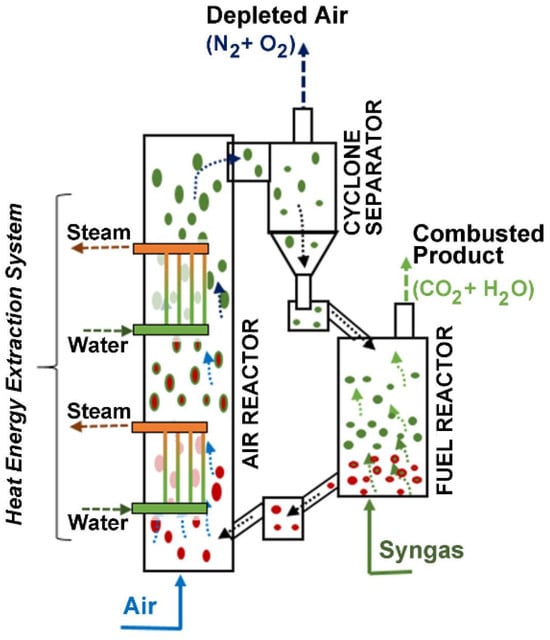
Figure 1.
Chemical looping combustion (CLC) process. Reprinted with permission from Ref [9]. Copyright (2020), American Chemical Society. Note: (a) Green is for MyOx particles, (b) Red is for MyOx-1 particles, (c) Arrows represent the upflow of gas either for air or syngas.
CLC yields an exiting combustion gas composed mainly of CO2 and water vapor, with minor amounts of other trace pollutants. By condensing the water vapor, CLC gives a highly concentrated CO2. This free-of-water CO2 is available to be sequestrated or eventually used in applications, such as the synthesis of jet fuel.
A description of the overall CLC reaction stoichiometry for the processing of syngas is provided below, with MyOx representing a generic metal oxide, using Equations (1) and (2):
Fuel Reactor: Reduction
Air Reactor: Oxidation
Once the fuel combustion is complete, the reduced metal-oxide MyOx−1 (OC) is transported to the Air Reactor where it is reoxidized with the oxygen from air, as described with Equation (2). As a result, this gives an exit stream from the Air Reactor, containing nitrogen as the major component and minor amounts of oxygen. Thus, exit gases are released with minimum negative environmental impact.
3. CLC Process Thermodynamics
The CLC process is subject to two important thermodynamic constraints as follows: (a) thermal levels have to be high enough to attain significant CLC conversions, and (b) the selected temperatures for the redox reactions (Equations (1) and (2)) must be below the OC material temperature limits.
A thorough CLC thermodynamic analysis was reported by McGlashan et al. [15]. This analysis considered the overall CLC process as being similar to the one of an internal combustion (IC) engine. On this basis, the overall process efficiency was determined by using the generated shaft work (Ws1). Figure 2 shows a representation of a CLC process while employing a NiO-based oxygen carrier.

Figure 2.
(a) BMD syngas CLC thermodynamics using a NiO oxygen carrier, an Air Reactor, and a Fuel Reactor, (b) BMD syngas conversion enthalpies for NiO reduction (Fuel Reactor), Ni oxidation (Air Reactor), and direct syngas combustion. Notes: (i) Red vertical arrows denote the exothermic Ni oxidation and the direct syngas combustion, while the (ii) blue vertical blue arrow denotes the endothermic syngas NiO reduction.
In a BMD syngas CLC process, the resulting shaft work () involves both the Air Reactor and the Fuel Reactor net enthalpies and the unit heat losses (), as described in Figure 2. In particular, and assuming that (adiabatic units) in both the oxidizer reactor and the reducer reactor, the overall efficiency can be defined as follows:
with representing the work performed in the CLC loop and
Furthermore, by applying the assumptions described by McGlashan et al. [15], a high reversible efficiency of the BMD syngas CLC system can be established as follows:
On this basis, and by using the data reported in Table 1, a efficiency of 97–99% for CLC was obtained when using NiO as oxygen carrier and syngas as a fuel. It is also expected that given that the proposed NiO-γAl2O3 oxygen carrier is limited in its operability because it cannot be used at temperatures above 700 °C, its net CLC efficiency in the twin circulating beds (Air Reactor and Fuel Reactor) is 48.6%, as described with Equation (5):
with being the efficiency of the CLC unit, and being the theoretical Carnot efficiency, converting into electrical power.

Table 1.
Enthalpies and entropies of reduction and oxidation for two types of BMD syngas at 298 K. Notes: (a) Syngas-133, (b) Syngas-250. Further details provided in Appendix A.
In summary, the reported results show that NiO-based OCs have the potential to be valuable for industrial CLC applications that use BDM syngas. This is because, in this case, the is much smaller than the , with most of the available enthalpy being utilized for power generation.
4. Oxygen Carrier Requirements
4.1. Oxygen Carriers for CLC
The various requirements for an enhanced OC performance are listed below [6,7]. They include the following:
- Favorable OC thermodynamics for BMD syngas conversion via CLC at the selected temperatures and pressures [16,17]. This is important to minimize the endothermic nature of the OC reduction reactions.
- An OC with good fluidizability properties at the anticipated CLC operating conditions. This is essential for a CLC process configured with circulating beds where fluidization in both the Air and the Fuel Reactor is considered.
- An OC with a high capacity for oxygen transport from the Air Reactor to the Fuel Reactor. This is significant to minimize the OC recirculating flow.
- An OC showing high reactivity and high stability in both the Air Reactor and the Fuel Reactor. This is important to decrease the CLC operational process costs, given that, without these properties, frequent replacements of the used OC with a fresh OC sample will be required.
- A high resistance of the OC to particle attrition with little elutriated solids and negligible solid agglomeration. This is critical to minimize oxygen carrier losses and frequent oxygen carrier replacement impacting in the CLC process operational costs.
- A small carbon deposition on the OC in the Fuel Reactor. If this is not the case, the deposited carbon on the OC, released in the Air Reactor as CO2, will reduce the desired high CO2 separation efficiency of the CLC process.
- An OC with a low manufacturing cost and with insignificant environmental impact.
Furthermore, and regarding the various OC properties, one can notice that pure metal oxides do not comply with the above described criteria, with reactivity declining after several redox cycles [18]. This points to the fact that a good OC having a high specific surface area with good fluidization characteristics and high attrition resistance such as is the case with γ-Al2O3 [19] is a must for CLC to be implemented successfully.
4.2. OC Preparation Methods
OC preparation methods have an important influence on OC performance and OC stability. Several well-established methods are available for OC preparation, such as the following: (a) co-precipitation, (b) freeze granulation, (c) incipient wetness impregnation, (d) natural mineral grinding, (e) sol–gel, (f) spray drying, and others. These methods were initially developed for catalysts [20] and then were extended to OCs. Table 2 reports different oxygen carrier preparation methods along with their advantages and disadvantages [21].
Table 2.
Oxygen carrier preparation methods.
When the pros and cons of these OC preparation methods are evaluated, the incipient wetness impregnation appears to be the most suitable in order to accomplish high metal dispersion over a selected support [34,35,36]. Furthermore, from the various methods listed, it was found that the incipient wetness impregnation provides the best control of metal loading, given that essentially all of the OC precursor containing solution components are quantitatively transferred to the OC support during support impregnation. One has to consider, however, that the incipient wetness impregnation, while being feasible for large-scale OC preparation, requires special care in order to prevent non-uniform metal dispersion in the OC support pore structure. Given all of these issues, the HPOC developed by our research team was synthesized using incipient wetness impregnation.
4.3. Proposed Oxygen Carriers
Research studies have been conducted employing Ni, Cu, Mn, Co, and Fe as OCs. In addition, various metal oxide supports (e.g., Al2O3, TiO2, SiO2,) have also been considered to develop stable and fluidizable oxygen carriers.
Table 3 reports the OCs frequently used in pilot-scale testing, as reported in the technical literature. Table 3 also provides comments regarding the following: (a) the type of testing units larger than 2 kW unit used, (b) the fuel conversion performance obtained, and (c) the synthesis methods of the OCs used.
Table 3.
Oxygen carriers used in CLC units larger than 2 kW.
OC particles may cluster or form unwanted chemical species via metal–support interactions [43,44,45]. Thus, an OC should also be selected with the objective of minimizing such effects.
As a result, and based on thermodynamics (refer to Section 3), NiO is considered as a good option for CLC. However, non-supported NiO particles showed modest performance in repetitive redox cycles. This was assigned to the Ni crystallites tendency to form agglomerates [46]. In contrast, NiO dispersed on γ-Al2O3 could be considered as an attractive option for CLC. The γ-alumina support provides high stability to the OC at high temperatures [47,48,49]. Furthermore, the γ-Al2O3 support particles display excellent fluidization properties, making the prepared OC appropriate for fluidized bed CLC processes.
However, when employing dispersed NiO on an γ-Al2O3 support, unwanted interactions between the metal oxide and the support may occur, with this leading to NiAl2O4 formation [34,35,50]. To account for this undesirable event [51], NiAl2O4 itself has been proposed as a support instead. However, the use of NiAl2O4 as an OC support limits the nickel crystallite density on the OC surface, making the CO2 yield of the CLC process less predictable. Thus, it can be seen that there are still significant challenges that need to be addressed in the implementation of NiAl2O4 as a support for OCs.
Concerning Ni-based OCs, it has been shown that they can provide a 1.84–6wt% oxygen transport capacity, with 40–50wt% NiO conversion at 750–1000 °C under excess oxygen conditions [52,53]. Nonetheless, these OCs display low stability due to metal support agglomeration. However, Ni-based OCs, modified with La and Co, display high thermal stability and very limited metal–support phase interactions [34,50]. It was demonstrated when evaluating the performance of these OCs, using methane as fuel, that they can yield a 1.84–3.45% -O- transport capacity and a 40–72% NiO conversion at lower temperatures (e.g., 600–680 °C).
5. NiO-Based Oxygen Carriers in BMD Syngas CLC
Nickel-based OCs have been used in several methane CLC studies. However, there is limited research that employs them in BMD syngas CLC. Table 4 reports a summary of the few syngas CLC studies where NiO-based OCs using α-Al2O3, γ-Al2O3, MgAl2O4, and NiAl2O4 supports were employed. Evaluations were developed by utilizing fixed bed thermogravimetric methods, temperature programmed oxidation and reduction methods, and the CREC Riser Simulator.
Table 4.
Syngas CLC studies using NiO-based OCs. Notes: Various designation codes are reported in the acronyms list.
γ-Al2O3 has received much attention as an OC support due to its specific surface area (190 m2/g) and the availability of the provided surface area for nickel dispersion [65,66]. However, given the possible nickel aluminate formation, these OCs are recommended to be used at temperatures lower than 750 °C in order to minimize the undesirable presence of nickel aluminate species [36,67].
Furthermore, avoiding the NiAl2O4 formation by incorporating cobalt into the γ-Al2O3 is another good approach for OC manufacturing [34]. In addition, it was found that controlling the temperature during the preparation of the OC also has a very significant beneficial effect, preventing the formation of nickel aluminate, and as a result, positively affecting the performance of the OC. Thus, as a consequence, and considering all these findings, the CREC-UWO team was able to develop an HPOC with negligible contained amounts of NiAl2O4 [9].
6. Preparation of the High-Performance Oxygen Carrier (HPOC)
As already stated in Section 5, OCs can display poor stability due to NiAl2O4 formation. Thus, a Ni-based OC has to be modified to minimize these effects. To accomplish this, a HPOC based on using Ni on γ-Al2O3 with La and Co dopants was designed and implemented at the CREC-UWO [34,50]. It was shown that when evaluating the performance of this HPOC, when using methane as fuel, that the HPOC can yield a 1.84–3.45% oxygen transport capacity, and a 40–72% NiO conversion, at 600–680 °C [52,53]. It was also proven that the developed HPOC displays good thermal stability and little Ni–alumina support interactions.
These HPOCs were prepared using the incipient wetness technique [34]. The preparation of the HPOC required that a sieved γ-Al2O3 support (Sasol CATALOX® SCCa 5/200, Sasol Limited, Sandton, Johannesbourg, South Africa) with 53–125 µm particles be added to a sealed conical glass flask. The used flask had a lateral outlet attached to a 250-mmHg vacuum line. Following this, the next steps carried out as follows:
(a) First Impregnation. La(NO3)3.6 H2O in a water solution was added to the fluidizable alumina support. This was followed by the drying of the resulting paste at 140 °C for 4 h. The obtained solids were reduced at 750 °C over 8 h under fluidized bed conditions using a 10% H2 balanced with Ar gas. La addition was performed in order to achieve a 5wt% La loading.
(b) Second Impregnation. A Co(NO3)2.6 H2O in a water solution was incorporated to the La–alumina particles under vacuum and intense solid mixing. This was followed by the drying of the resulting paste at 140 °C for 4 h, after which the solid particles were reduced at 750 °C for 8 h under fluidization conditions, employing a 10% H2 balanced with an Ar gas. This was conducted to achieve 1wt% Co loading.
(c) Third Impregnation. Ni(NO3)2.6 H2O in a water solution was added to the La–Co–alumina under vacuum and intense solid mixing. This was followed by the drying of the obtained paste at 140 °C for 4 h, after which the solids were reduced at 750 °C over 8 h in a fluidized bed, with 10% H2 balanced with Ar. This was conducted to achieve 10wt% Ni loading. The Ni impregnation was repeated twice to reach a combined 20wt% Ni and to obtain a desired HPOC formulation of 20wt% Ni, 1wt% Co, and 5wt% La.
Furthermore, the HPOCs prepared at CREC-UWO laboratories were characterized by using several methods. These techniques included XRD, BET, H2-TPO, TPR, NH3-TPD, and pulse chemisorption. It was confirmed that the HPOC displayed favorable properties including (a) a 107.5 m2/g surface area, (b) a 0.35 cm3/g pore volume and a 146A average pore size, (c) 1.27% Ni dispersion, (d) 77A Ni crystallite sizes, (e) reduced support acidity, (f) very stable OC oxidation reduction cycles, and (g) the minimum formation of nickel aluminate. Additional details regarding both the HPOC preparation methods and the oxygen carrier characterization methods are reported in [10].
7. CREC Riser Simulator to Establish HPOC Performance
To evaluate HPOCs for BMD syngas CLC, it is important to develop reactivity studies. Our research team decided to use a batch mini-fluidized bed reactor unit, designated as the CREC Riser Simulator. This device was invented by de Lasa in 1992 [68,69], with further enhancements being introduced in 2019 [70,71]. While there are other possible laboratory bench reactor alternatives that can be used for the evaluation of CLC kinetic studies, the CREC Riser Simulator is the unit most recommended to match the reaction operating parameters of industrial-scale circulating fluidized beds. This is particularly the case if one envisions the CLC process as a combination of a twin Riser Air Reactor and a Downer Fuel Reactor unit, as described in Figure 1. This type of unit can assist in the development of kinetic models, helping with accurate simulation calculations and the design of large-scale CLC reactors.
In the last 25 years, in addition to CLC, the CREC Riser Simulator has helped to elucidate the kinetics of a number of catalytic reactions such as the following: (a) the steam and dry reforming of methane, (b) the catalytic and thermal gasification of biomass, (c) the oxidative hydrogenation of light gases, and (d) the catalytic desulfurization of gasoline, among others [34,66,72,73,74,75,76,77,78,79,80,81,82]. Regarding CLC, the methane CLC in the CREC Riser Simulator was developed by the CREC-UWO team in the early phases of our research [10,58]. In spite of its special features, there are no articles apart from those of the CREC research team [8,9] that study BMD syngas conversion under CLC’s short reaction times in the CREC Riser Simulator.
Figure 3a,b show the CREC Riser Simulator, which includes the reactor itself (catalyst basket, impeller, cooling jacket), and its auxiliary unit components (4PV, 6PV, vacuum box, mass flow controller, gas chromatograph).
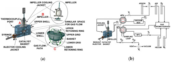
Figure 3.
(a) The CREC Riser simulator, (b) the CREC Riser simulator and its auxiliary equipment components. Reprinted with permission from Ref [71]. Copyright (2022), MDPI. Notes: (A) CREC Riser Simulator, (B) CREC Riser Simuator Impeller, (C) CREC Riser Simulator Basket.
The mini-fluidized CREC Riser Simulator is equipped with a rotating upper impeller and a central basket. The basket is manufactured with upper and lower grids in order to ensure that the solids (e.g., catalyst, OC) under evaluation are contained securely. The rotation of the impeller produces an upflow of gas in the center of the basket allows solid particles to be fluidized, with the recirculated gas flowing down in the outer basket section. Thus, this unit allows the fluidization of particles, with intense gas mixing. At 4000 rpm impeller rotational speeds, the high gas recirculation yields a quasi-constant gas phase species concentration. Given the strong gas mixing and simultaneous particle fluidization inside the CREC Riser Simulator basket, the CREC Riser Simulator operates as a “fluidized batch reactor” at quasi-isothermal conditions, as shown by Equation (6):
with VT being the total reactor volume in cm3, Ci being the mass concentration of any of the “i” chemical species in g/cm3, t being the reaction time in seconds, ri being the reaction rate of the species formed or consumed in grams of syngas species/(gOC. s), and W being the mass of OC in grams.
Thus, and in agreement with Equation (6), reaction times in the CREC Riser Simulator are equivalent to residence times in a continuous riser reactor, or alternatively in a continuous downer reactor. This closeness of reaction times in the 2–40 s range allows one to anticipate the OC performance in CLC twin circulating fluidized beds.
Figure 4 displays the pressure profile occurring in a typical CREC Riser Simulator run, lasting 30 s. It shows the sudden pressure increase at the injection of syngas, followed by a modest augmentation of pressure during the OC reduction, and ending with an abrupt pressure decrease, which corresponds with the almost instantaneous evacuation of the reactor basket contents to the vacuum box. These gaseous species consist of the unconverted syngas, as well as formed CO2 and water. Following this, these gaseous chemical species in the vacuum box are analyzed using a 6PV and gas chromatography unit, as shown in Figure 3b.
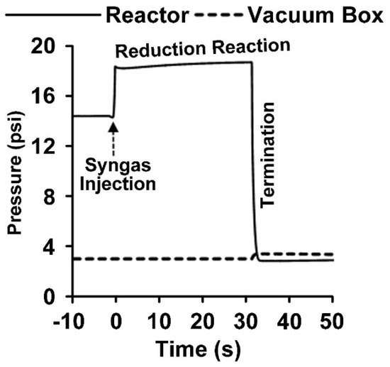
Figure 4.
Pressure changes during a reactivity test using the HPOC and BMD syngas. The pressure profile shows the phases in a run which include the BMD syngas injection, reduction period, and termination (evacuation). Reprinted with permission from Ref [8]. Copyright (2020), American Chemical Society.
On the basis of the GC analysis and the data gathered from every run, the H2, CO, and CH4 syngas conversions, and the CO2 yields, were calculated as follows:
with being the moles of species and with being either , , , and , denoting the moles of elemental oxygen.
Figure 5a,b report the typical results obtained when testing the HPOC with BMD syngas in the CREC Riser Simulator, mimicking the CLC process at ψ = 0.5 (moles of syngas/moles of NiO) and 550–650 °C. Here, one can see a progressive increase in the CO2 yields reaching 90% with a 33% OC conversion at 40 s of reaction time.
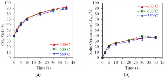
Figure 5.
HPOC performance: (a) CO2 yields, (b) NiO conversions. Data for Syngas-250, Syngas/NiO molar ratio = ψ = 0.5, temperature: 550–650 °C, reaction times: 0–40 s. Reprinted with permission from Ref [8]. Copyright (2019), American Chemical Society.
Figure 5a shows that high 90% CO2 yields can be achieved with , , and syngas component conversions exceeding 80%, as reported in Figure 6a,b, using a HPOC. This is the case under operating conditions mimicking those of an industrial CLC unit, with temperatures in the 550–650 °C range. These results show that temperatures in this range have a mild effect on OC performance.
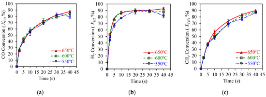
Figure 6.
HPOC performance: (a) CO conversion, (b) H2 conversions, (c) CH4 conversion. Data for Syngas-250, Syngas/NiO molar ratio = ψ = 0.5, temperature: 550–650 °C, reaction times: 0–40 s. Reprinted with permission from Ref [8]. Copyright (2019), American Chemical Society.
8. CLC Reaction Network
In order to establish a syngas CLC reaction model for a NiO-based OC, a suitable reaction mechanism for the anticipated 550–650 °C conditions is required [83,84].
Equation (10) represents the overall stoichiometry, describing the oxidation of the NiO oxygen carrier in the Air Reactor as follows:
Table 5 describes a number of possible reactions, enthalpies of reaction, and equilibrium constants that can be calculated using the syngas components (CO, H2, CH4, CO2), and a NiO-based HPOC. All of these reactions may contribute, to various extents, to the overall nickel oxide reduction as follows:
Table 5.
Enthalpies of reaction at standard conditions and chemical equilibrium constants for the postulated NiO reactions in the fuel reactor. The formation species enthalpies and entropies are from [85,86].
Table 5 also reports the chemical equilibrium constants (Keq) at 600 °C and at 1 atm. These are the operating conditions close to the ones of industrial-scale CLC reactors. One can observe in Table 5, that Reactions 1, 2, 3, 4, and 5 all display Keq values much larger than 1. While the various reactions listed in Table 5 are thermodynamically allowed, in practice, Reaction 3 is preferred versus Reactions 1 and 2. This is the case given that Reaction 3 involves a single NiO site in every reduction step, and as a result, is considered as mechanistically more feasible [10,87].
Table 6 reports three additional reactions that may occur in CLC. These reactions involve gas phase chemical species that may potentially influence the CLC product distribution. These reactions are described in Table 5, as follows: (a) the dry reforming of methane (DRM-Reaction 6), (b) the water gas shift reaction (WGSR-Reaction 7), and (c) the steam reforming of methane (Reaction 8).
Table 6.
Enthalpies of reaction at standard conditions and chemical equilibrium constants for postulated gas phase species reactions in the Fuel Reactor.
Table 6 shows that the dry reforming of methane (DRM), or Reaction 6, and the steam reforming of methane (SRM), or Reaction 8, are not favored thermodynamically, given that these reactions have Keq values of 0.119, and 0.18, respectively. Furthermore, one can also observe in Table 6 that the water gas shift reaction (WGSR), or Reaction 7, shows a Keq of 1.54 at 1 atm and 600 °C. Thus, while one can notice that the WGSR is moderately thermodynamically allowed, one can also observe that the prevailing oxidation state of the nickel species in the OC is NiO, as shown in Figure 5b. As a result, it was considered that the catalytic driven Reaction 7 does not have an influence in CLC, and that all these three reactions (Reactions 6, 7, and 8) can be omitted from the CLC kinetics model.
Finally, one is able to account for the coke in the CLC kinetic model by including the formation–consumption coke reactions as described via (19)–(22):
In this respect, one should note that the accounting of coke in CLC, both for the development of kinetics as well as for chemical equilibrium property predictions, is a challenging issue. For instance, the calculation of deposited coke using the C species, as shown in Equations (19)–(22), is an oversimplification and should not be used. On the other hand, the “x”, “y”, and “z” parameters of the recommended coke formula () cannot be established with certainty. This affects the exact formulation of coke reaction stoichiometries and their thermodynamic equilibria. Fortunately, the net coke formed in the CLC process under the conditions studied in the CREC Riser Simulator is very small [88], and therefore, the effect of coke on the overall CLC reaction network can be neglected.
Thus, it can be argued that based on various stoichiometric and thermodynamic considerations, one can select the following set of reactions for kinetic modeling: (a) Reaction 3 (Equation (13)), which is an irreversible reaction, and (b) Reactions 4 and 5 (Equations (14) and (15)), which include forward and backward reaction terms.
9. Kinetics of CLC Using HPOC
A kinetic rate equation for syngas CLC has to provide the needed information regarding HPOC conversion rates, in both reduction and oxidation cycles. The observed energies of activation for various Ni-based oxygen carriers on Al2O3 supports, reported in the technical literature, are shown in Table 7 [7].
One can observe in Table 7 that the magnitudes of the energies of activation obtained for methane, hydrogen, and carbon monoxide reduction are in the 39–78 kJ/mole, 26–96 kJ/mole, and 18–27 kJ/mole ranges, respectively. Furthermore, one can also notice that the oxidation energies of activation are in the 22–44 kJ/mole range for nickel oxidation. These are all indicators that point towards the value of implementing CLC processes at higher temperatures. While this is true, one should note that high temperatures are limited by the thermal stability of the selected OC, as is the case with the HPOC support which is limited to 750 °C.
However, for the simulation of the CLC process using a fluidizable HPOC, it is required to have available intrinsic syngas reduction kinetics. These kinetics are applicable to the small size HPOC particles (e.g., 30–100 micron range), and should involve rates not limited by particle mass and heat transfer. Furthermore, it was also desirable that the HPOC intrinsic kinetics be mechanistically sound, accounting for various possible phenomenological-based mechanistic steps such as the following: (a) nucleation, (b) geometrical contraction, (c) diffusion, (d) reaction order, and (e) Arrhenius law [89,90].
Both the Nucleation Nuclei Growth Model (NNGM) [66,91,92] and the Shrinking Core Model (SCM) [93,94,95] have been employed by others. However, from these two models, the NNGM has been the one favored by our research team [90]. The NNGM considers that once the nickel site reduction is finalized, only then is the oxygen reduction in the neighboring unreacted NiO site started. Factors in this analysis are given by the fact that metal crystallites dispersed in a porous support (e.g., γ-Al2O3) may have imperfections such as cracks, surface, and point defects [96]. The OC areas may provide nucleation sites where the activation energies display minimum values [97].
Table 7.
Reduction and oxidation kinetic parameters reported in the technical literature for Ni-based OCs using various fuels.
Table 7.
Reduction and oxidation kinetic parameters reported in the technical literature for Ni-based OCs using various fuels.
| OC/Support | Conditions/Reactants | Kinetics | Activation Energy (kJ/mole) | References |
|---|---|---|---|---|
| 60wt% NiO/Al2O3 | TGA (600–950 °C), H2 and CH4 | SCM | [93,98] | |
| 20wt% NiO-/Al2O3 | TPR-TPO (200–750 °C) H2 and O2 | NNGM | [58] | |
| 20wt% NiO/Co-Al2O3 | TPO, TPR (200–750 °C) CREC-RS (650 °C) H2 and O2 | NNGM | [99] | |
| 20 wt% NiO/Al2O3 | CREC-RS (680 °C) CH4 | SCM, NNGM, PLM | [35] | |
| 20wt% NiO/La-Al2O3 | TPR,TPO (200–750 °C) CREC-RS (650 °C) H2 and CH4 | NNGM | [66] | |
| 40wt% NiO/NiAl2O4 | TPR (300–600 °C) | SCM | [63] | |
| 65wt% NiO/Al2O3 | TGA (800–950 °C) H2 and CH4 | SCM | [94] | |
| 15wt% NiO/Al2O3 | Fixed Bed (600–900 °C) CH4, H2, CO | MVM | [100] | |
| 40wt% NiO/NiAl2O4 | TGA (750–1000 °C) CH4, H2, CO | SCM | [101] | |
| 18wt% NiO/Al2O3 | TGA (700–950 °C) H2, CO, O2 | SCM | [52] |
Notes: (a) Model codes reported in the acronyms list, (b) : energies of activation for CLC reactions involving methane, carbon monoxide, and hydrogen in the Fuel Reactor, respectively, and (c) : energy of activation for nickel oxidation in the Air Reactor.
It should be noted that reduction reactions with nickel oxide, including Reaction 3 and the forward Reactions 4 and 5, as shown in Table 5 (Equations (13)–(15)), can be considered as first order functions of the CH4, CO, and H2 partial pressures, respectively [50,84,100]. Furthermore, Reactions 4 and 5 (Equations (14) and (15)) can also be accounted for by including the reverse influence of CO2 and H2O conversion reactions. These reverse reactions are assumed to be first order functions of CO2 and H2 partial pressures. Furthermore, assuming a NNGM random nucleation (n = 1), the CLC kinetics can be expressed as follows:
with and being the forward and backward reaction terms in Equation (16), and being the forward and the backward reaction rates in Equation (17), and being the fraction of remaining active NiO sites. Furthermore, , is the pre-exponential factor, is the apparent activation energy, and is the 600 °C centering reaction temperature. It is strongly recommended to use in to reduce cross-correlation between kinetic parameters.
CLC intrinsic rates (−), can be established in CREC Riser Simulator as follows:
where represents the moles of “” species (µmole), stands for the reactor volume (), denotes the partial pressure (), is the universal gas constant (), represents the reactor temperature (), and stands for the reaction time ().
Given that and are constant during an experimental run, Equation (26) can be rewritten in terms of the individual chemical species partial pressures as follows:
Furthermore, by combining Equations (23)–(25) and (27), this leads to Equations (28)–(32). Equation (33) describes the total change in the α fraction of the reduced NiO active sites, with representing the initial moles of nickel oxide:
With the ratio and representing the weight of oxygen carrier used in the experiments.
Equations (28)–(33), which include and , were determined numerically using the following procedure: (a) Initial values were assigned to and , (b) then, Equations (28)–(33) were solved by using the “ode45” from MATLAB R2024b, and (c) finally, the and were adjusted, by using a non-linear “lsqnonlin” optimization method, minimizing the following function:
With and being the “” species partial pressures (, and ) predicted and measured, and and being the theoretical and experimental OC oxygen conversions.
Kinetic parameters were assessed for the HPOC by using both Syngas-250 and Syngas-133 [8]. Table 8 reports the estimated parameters with their percentual 95% confidence spans. This table shows that these confidence spans fall in a close-range, suggesting kinetic model adequacy, and the independence of the determined kinetic parameters from the syngas composition. Ten kinetic parameters were determined by using 250 observed data points, with at least three repeats per experiment, with a DOF (degree of freedom) of 240. Furthermore, additional studies evaluating the ten-parameter cross-correlation matrix show all cross-correlation coefficients being below one, with this providing additional support to the proposed kinetic model.
Table 8.
Kinetic parameters determined using Syngas-250 and Syngas-133 and the HPOC [8].
Table 8 also reports the frequency factors for the forward reactions. This shows k10 < k20 < k30 differences, with these differences agreeing with the observed . Regarding the backward reactions, the k40 and k50 parameters display a k40 < k50 difference, with this confirming the high H2O reactivity versus the reactivity of CO2 on the reduced nickel sites. In other words, the retardation rates due to the reverse reactions are more significant for H2 than for CO2.
Figure 7 and Figure 8 display the parity plots for Syngas-250 and Syngas-133. These figures compare the predicted and experimentally observed chemical species’ partial pressure values, at different reaction times, temperatures, ψ ratios, and using the HPOC.
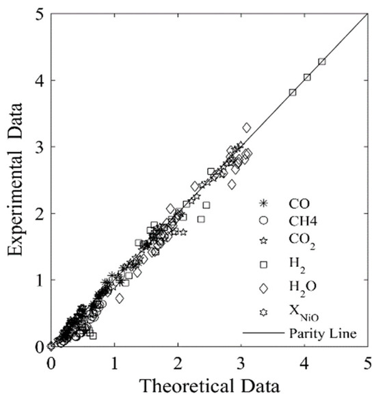
Figure 7.
Experimental chemical species partial pressures obtained using the Syngas-250, and the HPOC compared with those predicted by the model. Data reported: 250 data points. Every data point is the average for at least 3 repeats. Note: standard deviation = 2.9%. Reprinted with permission from Ref [8]. Copyright (2019), American Chemical Society.
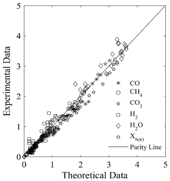
Figure 8.
Experimental chemical species partial pressures obtained using the Syngas-133 and an HPOC compared with those predicted by the model. Data reported: 250 data points. Every data point is the average from for at least 3 repeats. Note: standard deviation = 3.9%. Reprinted with permission from Ref [8]. Copyright (2019), American Chemical Society.
One can see that runs with Syngas-250 showed a 2.9% standard deviation error, while the runs with Syngas-133 displayed a 3.9% standard deviation error [8]. Both of these standard deviation errors are acceptable and within the anticipated experimental error bands. As a result, both the kinetic parameters and the kinetic model considered using two BMD syngas samples are considered adequate for the CLC while using the HPOC.
10. Large-Scale and Demonstration CLC Unit Simulation
Table 9 reports a summary of CLC fluidized bed units available at various research centers around the world. This demonstrates the far-reaching research on CLC technology that is being developed currently in different countries.
Table 9.
Pilot-scale CLC fluidized bed units available at various research centers around the world.
In this respect, Table 9 shows the significant number of CLC units employed based on the twin fluidized bed design, and, in particular, the bubbling bed combined with a riser, a moving bed, and fast fluidization. While these configurations can provide suitable results, the downer–riser configuration was preferred for the HPOC [108]. This was the case given the anticipated close plug flow operation in those units, and as a consequence the anticipated high syngas conversions, CO2 yields, and oxygen carrier regeneration efficiencies.
Table 10 describes the active research being developed with computer-based simulations for the advancement of OCs to be used in large-scale CLC units. Furthermore, one can also mention the significant and valuable efforts being developed to validate the proposed models with experimental data [109].
Table 10.
Simulations of the large-scale CLC process employing various OCs. Adapted from [7].
While all these efforts are commendable, Ahmed and de Lasa [108] recently reported research involving the simulation of a 36.6 kW CLC reactor, consisting of an Air Riser Reactor–Fuel Downer Reactor unit with the following dimensions: (a) Air Reactor: diameter: 0.12 m, height: 8.0 m; (b) Fuel Reactor: diameter: 0.20 m, height: 6 m. Simulations involved Computational Particle Fluid Dynamics (CPFD) implemented in conjunction with the HPOC reduction kinetics, as described in Section 8.
Figure 9 shows a schematic representation of the CLC unit proposed by Ahmed and de Lasa [108]. The HPOC particles flow downwards from the bottom of a cyclone encountering BMD syngas jets. The BMD syngas jets are supplied to the downer via a gas distributor injection port. Thus, HPOC particles are mixed uniformly with the syngas fed before they move downwards.
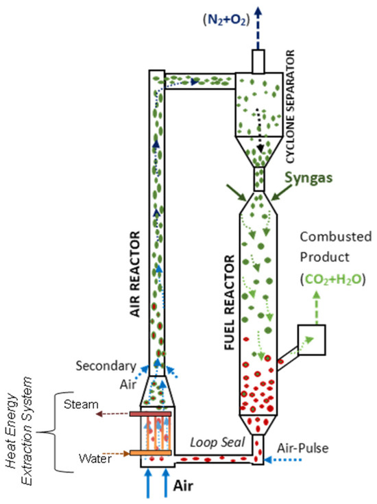
Figure 9.
Schematic diagram of a Downer Fuel Reactor and a Riser Air Reactor configuration and their auxiliary components in a CLC process. Reprinted with permission from Ref [102]. Copyright (2020), American Chemical Society. Notes: (a) Green for oxidized HPOC particles, (b) Red for reduced HPOC particles, (c) Arrows for director of the circulating gas-soild suspension.
Regarding the downer design, both the downer dimensions (e.g., height, diameter) are selected to warrant that the gas volumetric flow, and the OC residence times provide the desired high syngas conversions. Furthermore, the cyclone is designed to provide efficient HPOC particle separation, with minimum OC particle entrainment. In the selected CLC configuration, the Downer Fuel Reactor is connected to the Air Reactor via an L-type loop seal [108]. It is in this section where the recycled HPOC is forced to enter into the Air Reactor via an air pulsation system.
The twin CLC reactor system simulations were conducted using CPFD Barracuda VR software. These computations were carried out by employing an Eulerian–Lagrangian method, with computational particles having uniform species composition, size, density, and temperature [108]. The Barracuda VR software included an MP-PIC subroutine accounting for gas–particle and particle–particle interactions. In addition, the OC kinetics, described in Section 8 of this review, were accounted for in the Barracuda VR simulations. This enabled the simulation of a twin reactor scale CLC unit, using an affordable computational time. Additional details regarding the differential equations and the numerical approach using Barracuda are given in [114,115,116].
Table 11 reports the various HPOC properties considered in the CPFD simulations. These are as follows: (a) the particle mean diameter, (b) the particle density, (c) the particle sphericity, (d) the particle close pack volume fraction, d) the particle–wall tangential and normal retention coefficients, (e) the diffuse bounce, and (f) the maximum momentum redirection from particle-to-particle collisions.
Table 11.
Physical properties of HPOC particles.
Furthermore, in both the Riser Air Reactor and in the Downer Fuel Reactor, HPOC particles move as particle clusters rather than as individual particles. Therefore, the accounting of HPOC particle clusters was considered to be very important to accurately describe the downer hydrodynamics and as a result enable the gas–solid interactions in the Downer Fuel Reactor [70].
The CPFD Barracuda simulations also involved other significant applicable assumptions, such as that of the adiabatic and the quasi-isothermal operation of the Downer Fuel Reactor. This was considered adequate given the small OC reduction enthalpy in the Fuel Reactor, as reported in Section 3. Concerning the Air Reactor, it was also assumed that all the heat generated as a result of HPOC re-oxidation was removed in the lower Energy Extraction Air Reactor System, described in Figure 9.
CPFD Barracuda considers the Reynolds Averaged Navier–Stokes equations to simulate fluid dynamics in a 3D Downer Fuel Reactor. As a result, volume averaged mass continuity and momentum balances [117,118] can be considered for the gas phase, as shown in Equations (35) and (36):
where is the gas phase volume fraction, is the gas phase density, is the time, is the gas velocity vector, is the gas mass production rate in the gas phase per unit volume due to the particle-gas reaction, is the mean gas phase pressure, is the exerted particle force per unit fluid volume, is the acceleration vector due to gravity, and is the stress tensor in the gas phase.
Furthermore, the properties of the gaseous phase components were evaluated by solving the transport equation for the individual gas phase species, as follows:
with being the turbulent mass diffusivity (), µ representing the shear viscosity, which is the sum of laminar and turbulent viscosity [119], and denoting the turbulent Schmidt number.
The MP-PIC method employed in the simulations of the Downer Fuel Reactor considered a transport equation to describe particle phase dynamics. This equation includes a particle distribution function (PDF) [108]. Equation (38) expresses a PDF as . This f variable depends on the following: the HPOC location in space, the HPOC particle velocity, and the HPOC mass. The f variable is also affected by the A HPOC acceleration parameter, the D drag function, and the HPOC inter-particle normal stress.
The selected PDF includes a collision term (right-hand side of Equation (38)), as suggested by O’Rourke et al. [120].
Furthermore, for non-spherical HPOC clusters, with particle cluster distributions as given in Figure 10, the following Ganser Model [121] was considered adequate for drag calculations.

Figure 10.
Particle clusters in a Downer Reactor: Distribution of particle clusters for a 1.5 m/s gas velocity and a 50 kg/m2/s particle mass flux. Reprinted with permission from Ref [102]. Copyright (2020), American Chemical Society.
With ψ being the particle cluster sphericity and with c1, c2, n0, n1, n2, and n3 being 0.1118, 0.01794, 3305, 2.65, 0.6567, 1.8148, and 0.5743, respectively. In addition, K1 and K2 isometric shape parameters in Equation (41) are defined as and
Figure 11a describes the CPFD simulations while using the HPOC for the following operating conditions: (a) Syngas flow feed: 0.0059 kg/s, (b) Air flow feed: 0.010 kg/s, (c) Fuel Reactor temperature: 923 K, (d) Inlet Fuel Reactor pressure: 101 KPa. The results obtained are for the Downer Fuel Reactor and the Riser Air Reactor. Figure 11b,c show that 60 s computational times were needed to obtain a stabilized solid flow as well as an air flow and syngas flow in the Fuel and Air Reactor, respectively. Reported results are given at the designated “cut off” planes, as shown in Figure 11a.
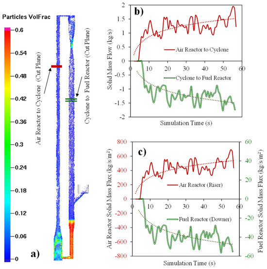
Figure 11.
Simulated HPOC circulation in a CLC unit: (a) Particle volume fractions at various unit locations, (b) particle flow rates at selected reference planes and at various computational times, and (c) particle mass fluxes at the selected reference planes and at various computational times. Reprinted with permission from Ref [102]. Copyright (2020), American Chemical Society.
Therefore, as reported in Figure 11a, 1.5 Kg/s HPOC circulation was used in the CPFD simulation with a 1–3% HPOC volume fraction in the Fuel Reactor after 60 s of computational time. In addition, and as is shown in Figure 11c, a 500 kg/s/m2 mass flux in the Riser Air Reactor and a 50 kg/s/m2 mass flux in the Downer Fuel Reactor can both be achieved. These values agree with typical experimental values and industrial requirements [122].
Figure 12a,b report the fluid velocity, the particle velocity, and the average volume fraction along the Downer Fuel Reactor unit, as calculated via CPFD simulations.
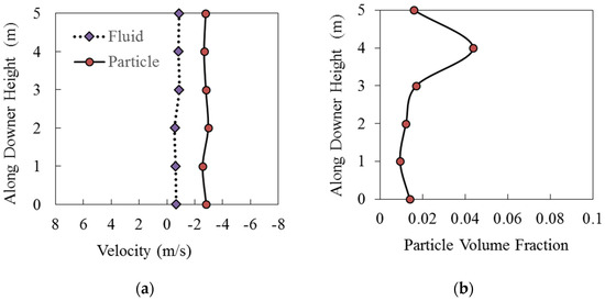
Figure 12.
Axial fluid and particle velocities along the CLC Downer Fuel Reactor length using the HPOC: (a) Particle and fluid velocity relative to downer height, (b) particle volume fraction relative to downer height. Reprinted with permission from Ref [102]. Copyright (2020), American Chemical Society.
One can notice from Figure 12a,b that the cross-section average particle volume fractions and cross-section average particle velocities are relatively constant. This is consistent with the quasi-isothermal conditions of the downer as well as with the modest change in the total number of moles in the Fuel Reactor while the reduction reaction is progressing. The only exception to this trend is in the downer section where the BMD syngas is fed. In this section, a particle densification was observed. However, once a distance of 1–2 m of downer length away from the BMD syngas feed level is reached, and the downer flow pattern is established, the particle volume fraction stabilizes in the 1% level, with the gas and cluster average velocities being at 0.75 m/s and 2.76 m/s, respectively.
Table 12 reports the calculated BMD syngas component conversions and CO2 yields for the Syngas-250 under isothermal conditions. Assessments were performed for a Downer Fuel Reactor having 3.75 m, 7.5 m, and 15 m heights, under the selected operating conditions: (a) syngas flow feed: 0.0059 kg/s, (b) air flow feed: 0.010 kg/s, (c) Fuel Reactor temperature: 923 K, (d) Inlet Fuel Reactor pressure: 101 KPa.
Table 12.
Calculated Syngas-250 components conversions and CO2 yields for downers of various heights (3.75 m, 7.5 m and 15 m) using the HPOC kinetics, described in Section 8.
One can observe, based on the results in Table 12, that the HPOC at a 15 m height in the Downer Fuel Reactor gives high syngas component conversions (99.6% for H2, 91.2% for CO, 71.9% for CH4) with high CO2 yields (87.0%). The CPFD results also show that the 1.5 kg/s HPOC circulation in such a configuration is possible, with a close to 1% solid volumetric concentration. The proposed 36 KW twin reactor CLC configuration also benefits from the little CO2 gas leaking, made possible by the implemented L-type loop-seal placed between Downer Fuel Reactor and Riser Air Reactor.
11. Conclusions and Future Perspectives
Industrial-scale fast catalytic fluidized beds, and especially CLC Downer Fuel Reactor units and Riser Air Reactor units, have the potential to provide the reaction environment for the efficient combustion of biomass-derived syngas. As a result, biomass-derived syngas could be used as fuel in power stations, avoiding the adverse ecological impact of employing fossil fuels. These fast-fluidized beds reactors can operate with high-performance fluidizable oxygen carriers (HPOC) free of particle mass and heat diffusional transport rate limitations. These fast-fluidized beds reactors can be operated with high syngas throughputs and short OC residence times, and can provide a high conversion of syngas components (CH4, H2, CO) into a free nitrogen CO2.
CLC thermodynamics is an area of significant importance for CLC process development and evaluation. For instance, it is proven in this review that when using NiO oxygen carriers, much smaller enthalpies are needed for oxygen carrier reduction than the ones required for the oxygen carrier oxidation. This allowed us to predict a 48.6% overall energy conversion efficiency with this favoring fluidizable NiO oxygen carriers for industrial-scale applications as a result.
Given the promise of HPOCs, this review focuses on the preparation of such oxygen carriers with their performance being demonstrated using a mini-fluidized CREC Riser Simulator. This experimental tool has the ability to anticipate the high syngas species conversion and CO2 yields that can be obtained in industrial size CLC fluidized bed units. On the basis of the data obtained in the CREC Riser Simulator, phenomenological-based kinetics, involving solid–gas reactions and NiO supported oxygen carriers, were successfully developed. This provided an adequate description of the HPOC performance and of the high CO2 yields obtained.
Furthermore, CPFD computations such as the ones obtained with Barracuda VR were shown to be valuable in order to account for the kinetics and the fluid dynamics in both the Downer Fuel Reactor and the Riser Air Reactor. These simulations demonstrated the scalability of an integrated Downer Fuel Reactor–Riser Air Reactor CLC unit with the proposed reactor configuration providing high 86% CO2 yields and a 85% overall conversion of syngas components.
Based on the state-of-the art CLC process described, one can predict that new HPOCs with low-cost preparation, stable performance, and very low fluidizable support attrition will be needed in the near future. One can also anticipate the great importance of conducting quick performance evaluations and developing mechanistic-based kinetics of OCs using laboratory scale tools, such as the CREC Riser Simulator, which emulate industrial-scale CLC unit operating conditions.
Furthermore, and to complement this research effort, it is anticipated that in the near future more refined CPFD simulations will be required for the full development of a Downer Fuel Reactor and a Riser Air Reactor combined twin unit process. It is also expected that the CLC design will require innovative components such as the following: (a) a L-type loop-seal located between Fuel Reactor and Air Reactor, (b) a syngas injection system placed at the top of the Downer Fuel Reactor unit, (c) high efficiency particle separation cyclones, and (d) Air Reactor vertical tube heat exchangers with minimum flow disturbance.
In summary, this review highlights the recent progress in CLC obtained with an HPOC oxygen carrier. It studies the potential value of a promising process where biomass-derived syngas is combusted with NiO, yielding CO2 and water as the sole products. The condensation of the water from the CLC outlet stream can lead to a highly concentrated CO2 gas stream ready to be either buried or alternatively be used together with green hydrogen for the synthesis of green fuels produced from renewable feedstocks.
Author Contributions
Conceptualization, H.d.L. and N.T.B.; methodology, H.d.L. and N.T.B.; software, N.T.B.; validation, H.d.L. and N.T.B.; formal analysis, H.d.L. and N.T.B.; investigation, H.d.L. and N.T.B.; resources, H.d.L.; data curation, N.T.B.; writing—original draft preparation, H.d.L.; writing—review and editing, N.T.B.; supervision, H.d.L.; project administration, H.d.L.; funding acquisition, H.d.L. All authors have read and agreed to the published version of the manuscript.
Funding
This reesearch was funded by the Natrural Sciences and Engineering Research Counci of Canada (NSERC-Canada) via the Hugo de Lasa-Research Discovery Grant. The APC was funded via MDPI publishers.
Data Availability Statement
Data will be available upon request.
Acknowledgments
We would like to gratefully acknowledge the financial support provided by the NSERC-Discovery Grant (2020-H. de Lasa grant), Canada, and RECAT Technologies Inc. We are also grateful for the technical advice provided by Imtiaz Ahmed and Samira Roston during the preparation of this manuscript. We would also like to thank Florencia de Lasa who provided valuable assistance in the editing of this manuscript and preparation of the graphical abstract.
Conflicts of Interest
The authors declare no conflict of interest.
Notation
| as per Equation (39) (s−1); | |
| Turbulent diffusivity (m2 s−1); | |
| Mass concentration of “i” chemical species in g/cm3; | |
| Activation energy methane conversion with NiO via CLC (kJ/mole); | |
| Activation energy CO conversion with NiO via CLC (kJ/mole); | |
| Activation energy hydrogen conversion with NiO via CLC (kJ/mole); | |
| Activation energy oxygen conversion with Ni via CLC (kJ/mole); | |
| 1/RT. (101325/14.7) unit conversion factor; | |
| Molar flow of the “i” in CLC products, with “i’ being the CO, H2 or CH4 (Kmol/s); | |
| Function of particle position (xp), velocity(up), mass (Mp) and time(t); | |
| Exerted particle force per unit fluid volume (newtons m−3); | |
| Gravity acceleration (m2/s); | |
| Pre-exponential frequency factor for the forward constant Reaction 3 (mol.m−3psi−1s); | |
| Pre-exponential frequency factor for the forward constant Reaction 4 (mol.m−3psi−1s); | |
| Pre-exponential frequency factor for the forward constant Reaction 4 (mol.m−3psi−1s); | |
| Pre-exponential frequency factor for the forward Reaction 3 (mol.m−3psi−1s); | |
| Pre-exponential frequency factor for the forward Reaction 3 (mol.m−3psi−1s); | |
| Forward kinetic constant for Reaction 3 (mol.m−3psi−1s); | |
| Forward kinetic constant for Reaction 4 (mol.m−3psi−1s); | |
| Forward kinetic constant for Reaction 5 (mol.m−3psi−1s); | |
| Backward kinetic constant for Reaction 4 (mol.m−3psi−1s); | |
| Backward kinetic constant for Reaction 5 (mol.m−3psi−1s); | |
| Chemical equilibrium constant for Reactions 3, 4 and 5 (-); | |
| Isometric parameters; | |
| Number of experimental data points; | |
| Mass of an OC particle cluster; | |
| Moles of i chemical species in CLC products, with “i’ being the CO, H2 or CH4; | |
| partial pressures of “i” chemical species (psi); | |
| Total pressure (atm); | |
| Heat loses in Fuel Reactor (kJ/s); | |
| Heat loses in Air Reactor (kJ/s); | |
| Heat discarded from the heat engine (kJ/s); | |
| Heat transfer from the Air Reactor (kJ/s); | |
| Reaction rate of the species formation, or the consumption of “i” species (grams of “i” species/(gcat s)); | |
| OC particle ratio (m); | |
| Universal gas constant (J/mole K); | |
| Particle Reynolds number (-); | |
| Schmidt dimensionless number (-); | |
| Reaction time in seconds; | |
| Temperature (°K or °C); | |
| Interstitial gas velocity (m s−1); | |
| Particle velocity (m s−1); | |
| Total reactor volume (cm3); | |
| Mass of oxygen carrier in grams; | |
| Shaft work extracted from the reversible thermal engine; | |
| Shaft work extracted from the CLC unit; | |
| in CREC Riser Simulator | |
| in a Downer Fuel Reactor; | |
| Molar fraction of the “i” component in the gas phase; | |
| in CREC Riser Simulator in a downer unit. |
Greek Symbols
| Fraction of converted NiO sites or Ni sites (-); | |
| Weight of OC per unit reactor volume (kg m−3); | |
| Enthalpy change from syngas oxidation in the Air Reactor (kJ/mole); | |
| Entropy change from syngas oxidation in the Air Reactor (kJ/mole K); | |
| Enthalpy change from syngas direct combustion; | |
| Entropy change resulting from syngas direct combustion (kJ/mole K); | |
| Overall efficiency = ηCLC, syngas. ηthermal,engine; | |
| Ø; | |
| Ws/(ΔHo)oxidation Ø; | |
| (ΔHo)oxidation/(ΔHo)syngas, ratio; | |
| Shear viscosity (Pa.s); | |
| (ΔS)oxidation/(ΔS)syngas ratio; | |
| Gas void fraction (-); | |
| Gas density (kg m−3); | |
| Particle density (kg m−3); | |
| Fluid stress tensor (Pa); | |
| Fluid particle tensor (Pa); | |
| Particle cluster sphericity (-). |
Acronyms
| BET | Brunauer–Emmett–Teller method for specific surface area; |
| BMD Syngas | Biomass-derived syngas; |
| CLC | Chemical looping combustion; |
| COP | Co-precipitation; |
| CPFD | Computational Particle Fluid Dynamics; |
| CREC-RS | Chemical Reactor Engineering Centre; |
| CREC-UWO | Chemical Reactor Engineering Centre, University of Western Ontario, Canada; |
| DIS | Dissolution; |
| IMP | Wet/incipient wetness impregnation; |
| MM | Mechanical mixing; |
| MP-PIC | Multi-phase particle-in-cell-fluid model; |
| MVM | Modified volumetric model; |
| NNGM | Nucleation and nuclei growth model; |
| pFxB | Pressurized fixed bed; |
| PLM | Power law model; |
| SC | Solution combustion; |
| SCM | Shrinking Core Model SD spray drying; |
| Syngas-133 | 44v% H2, 33v% CO, 11v% CH4, and 12v% CO2 gas blend; |
| Syngas-250 | 50v% H2, 20v% CO, 10v% CH4, and 20v% CO2 gas blend; |
| TGA | Thermogravimetric analyzer; |
| TPO | Temperature programmed oxidation; |
| TPR | Temperature programmed reduction. |
Appendix A. Validation of Enthalpy Assigned Calculation Values
As a process of validation and verification of the reaction enthalpies considered, it is valuable to show that the addition of the NiO reduction and of the Ni oxidation enthalpies in syngas CLC to comply with the condition given by the following equation:
with ΔHcombustion representing the enthalpy of direct syngas combustion.
In order to confirm this, the following definitions and calculations are required:
- (a)
- Thermodynamic Properties.
Calculations of the enthalpies of reduction for Reactions 3, 4, and 5 require the thermodynamic data, given in Table A1:
On this basis, one can calculate the heats of reaction for Reactions 3, 4 and 5 as described in Table 5, Section 7, and as shown below:
- Reaction 3: CH4 + NiO → Ni+ CO + 2 H2, ΔHR,3 = 204.41 kJ/mole;
- Reaction 4: H2 + NiO →H2O+ Ni, ΔHR,4 = − 1.7 kJ/mole;
- Reaction 5: CO + NiO →CO2 + Ni, ΔHR,4 = − 42.9 kJ/mole.
Table A1.
Enthalpy and Gibbs energy of formation for various chemical species.
Table A1.
Enthalpy and Gibbs energy of formation for various chemical species.
| Chemical Species | ΔHf298 (kJ/mole) | ΔGf298 (kJ/mole) |
|---|---|---|
| Reducing Gas | ||
| H2 | 0 | 0 |
| CO | −110.5 | −137.2 |
| CH4 | −74.8 | −50.5 |
| CO2 | −393.50 | −3944.4 |
| OC and O2 | ||
| NiO | −240.1 | −157.1 |
| Ni | 0 | 0 |
| O2 | 0 | 0 |
- (b)
- Reaction Enthalpy for Syngas-133 and NiO.
The overall heat of reaction for the Syngas-133 at complete reduction conditions can be calculated as follows:
Given the Syngas-133 molar composition, then syngas.
Furthermore, considering that 1.21 moles of NiO are needed to convert 1.21 moles of Syngas-133 fed, the heat of reduction based on the moles of NiO consumed, or the equivalent moles of O consumed, is given by Equation (A3):
- (c)
- Reaction Enthalpy for Syngas-250 and NiO.
Similar calculations can be developed for the Syngas-250 using Equation (A2) as follows:
Given the Syngas-250 composition, this gives ΔHreduction,250 = 6.391 kJ/mole syngas. Thus, one requires 1.1 moles of converted NiO per mole of Syngas-250 fed, yielding a heat of reduction based on the moles of NiO or O consumed and given by:
- (d)
- Enthalpy of Oxidation for Ni-based OC.
The enthalpy of oxidation of Ni-based OCs can be calculated on the basis of the Ni + ½ O2→NiO stoichiometry and the data of Table A1, with a resulting ΔHoxidation = −240 Kmole/NiO formed or O consumed.
- (e)
- Net enthalpy for the CLC process.
Furthermore, considering Equation (A1), the net enthalpy change for the CLC process can be calculated for Syngas-133 and Syngas-250 as follows:
and
- (f)
- Enthalpy of Direct Combustion.
The enthalpy for the direct combustion of the syngas with oxygen can be established as well using the heats of formation of the syngas and the heat of formation of CO2 and water as follows:
Thus, it can be observed that the algebraic sum of the enthalpy values assigned to both the oxidation and the reduction in the NiO oxygen carriers in CLC deviates by less than 0.1% with respect to the direct syngas combustion enthalpies. Thus, this validates the enthalpy values assigned as well as the assumption that the Syngas Downer Fuel Reactor functions under isothermal conditions. This is given by the following:
References
- Omoruyi, S.O.; Idiata, D.J. The Environmental and Cost Implication of Fossil Fuel Generators: New Benin Market, Benin City, Nigeria. Int. J. Eng. Tech. Adv. Eng. 2015, 5, 25–29. [Google Scholar]
- Carapellucci, R.; Milazzo, A. Membrane Systems for CO2 Capture and Their Integration with Gas Turbine Plants. Proc. Inst. Mech. Eng. Part J. Power Energy 2003, 217, 505–517. [Google Scholar] [CrossRef]
- Yang, H.; Xu, Z.; Fan, M.; Gupta, R.; Slimane, R.B.; Bland, A.E.; Wright, I. Progress in Carbon Dioxide Separation and Capture: A Review. J. Environ. Sci. 2008, 20, 14–27. [Google Scholar] [CrossRef]
- Zhao, H. 2024 Pioneers in Energy Research: Juan Adánez. Energy Fuels 2024, 38, 21666–21671. [Google Scholar] [CrossRef]
- Mahinpey, N.; Farooqui, A.; Abdalla, A.; Asghari, K. Chapter 12—Power Generation from Syngas. In Advances in Synthesis Gas: Methods, Technologies and Applications; Rahimpour, M.R., Makarem, M.A., Meshksar, M., Eds.; Elsevier: Amsterdam, The Netherlands, 2023; Volume 3, pp. 289–319. ISBN 978-0-323-91878-7. [Google Scholar]
- Hossain, M.M.; de Lasa, H.I. Chemical-Looping Combustion (CLC) for Inherent CO2 Separation-a Review. Chem. Eng. Sci. 2008, 63, 4433–4451. [Google Scholar] [CrossRef]
- Adanez, J.; Abad, A.; Garcia-labiano, F.; Gayan, P.; Diego, L.F. De Progress in Chemical-Looping Combustion and Reforming Technologies. Prog. Energy Combust. Sci. 2012, 38, 215–282. [Google Scholar] [CrossRef]
- Ahmed, I.; de Lasa, H. 110th Anniversary: Kinetic Model for Syngas Chemical Looping Combustion Using a Nickel-Based Highly Performing Fluidizable Oxygen Carrier. Ind. Eng. Chem. Res. 2019, 58, 2801–2811. [Google Scholar] [CrossRef]
- Ahmed, I.; de Lasa, H. Syngas Chemical Looping Combustion Using a Highly Performing Fluidizable Oxygen Carrier. Catal. Today 2020, 343, 63–71. [Google Scholar] [CrossRef]
- Quddus, M.R. A Novel Mixed Metallic Oxygen Carrier for Chemical Looping Combustion: Preparation, Characterization & Kinetic Modeling; Western University: London, ON, Canada, 2013. [Google Scholar]
- Lewis, W.K.; Gilliland, E.R. Production of Pure Carbon Dioxide. U.S. Patent 2665971A, 12 January 1954. [Google Scholar]
- Lewis, W.K.; Gilliland, E.R.; Reed, W.A. Reaction of Methane with Copper Oxide in a Fluidized Bed. Ind. Eng. Chem. 1949, 41, 1227–1237. [Google Scholar] [CrossRef]
- Richter, H.J.; Knoche, K.F. Reversibility of Combustion Processes. In Proceedings of the ACS Symposium Series; American Chemical Society: Washington, DC, USA, 1983; pp. 71–85. [Google Scholar]
- Ishida, M.; Zheng, D.; Akehata, T. Evaluation of a Chemical-Looping-Combustion Power-Generation System by Graphic Exergy Analysis. Energy 1987, 12, 147–154. [Google Scholar] [CrossRef]
- McGlashan, N.R. Chemical-Looping Combustion—A Thermodynamic Study. Proc. Inst. Mech. Eng. Part C J. Mech. Eng. Sci. 2008, 222, 1005–1019. [Google Scholar] [CrossRef]
- Hossain, M.M. Chemical-Looping Combustion with Gaseous Fuels: Thermodynamic Parametric Modeling. Arab. J. Sci. Eng. 2014, 39, 3415–3421. [Google Scholar] [CrossRef]
- Svoboda, K.; Slowinski, G.; Rogut, J.; Baxter, D. Thermodynamic Possibilities and Constraints for Pure Hydrogen Production by Iron Based Chemical Looping Process at Lower Temperatures. Energy Convers. Manag. 2007, 48, 3063–3073. [Google Scholar] [CrossRef]
- Ishida, M.; Jin, H. A Novel Chemical-Looping Combustor without NOx Formation. Ind. Eng. Chem. Res. 1996, 35, 2469–2472. [Google Scholar] [CrossRef]
- Ishida, M.; Jin, H. A Novel Combustor Based on Chemical-Looping Reactions and its Reaction Kinetics. J. Chem. Eng. Jpn. 1994, 27, 296–301. [Google Scholar] [CrossRef]
- Bartholomew, C.H.; Farrauto, R.J. Fundamentals of Industrial Catalytic Processes, 2nd ed.; Wiley: Hoboken, NJ, USA, 2006; ISBN 978-0-471-45713-8. [Google Scholar]
- Daneshmand-Jahromi, S.; Sedghkerdar, M.H.; Mahinpey, N. A Review of Chemical Looping Combustion Technology: Fundamentals, and Development of Natural, Industrial Waste, and Synthetic Oxygen Carriers. Fuel 2023, 341, 127626. [Google Scholar] [CrossRef]
- Abdalla, A.; Tijani, M.M.; Mohamedali, M.; Mahinpey, N. The Effects of WO3 Addition to NiO/ZrO2 Oxygen Carriers for Chemical Looping Combustion of Methane. J. Environ. Chem. Eng. 2022, 10, 106945. [Google Scholar] [CrossRef]
- Mattisson, T.; Johansson, M.; Lyngfelt, A. The Use of NiO as an Oxygen Carrier in Chemical-Looping Combustion. Fuel 2006, 85, 736–747. [Google Scholar] [CrossRef]
- Stevens, R.W.; Newby, R.A.; Keairns, D.; Woods, M. Oxygen Carrier Production Cost. In Proceedings of the Clearwater Clean Energy Conference Clearwater; National Energy Technology Laboratory (NETL): Pittsburgh, PA, USA; Morgantown, WV, USA, 2019. [Google Scholar]
- Jerndal, E.; Mattisson, T.; Thijs, I.; Snijkers, F.; Lyngfelt, A. Investigation of NiO/NiAl2O4 Oxygen Carriers for Chemical-Looping Combustion Produced by Spray-Drying. Int. J. Greenh. Gas Control 2010, 4, 23–35. [Google Scholar] [CrossRef]
- Johansson, M.; Mattisson, T.; Lyngfelt, A. Comparison of Oxygen Carriers for Chemical-Looping Combustion. Therm. Sci. 2006, 10, 93–107. [Google Scholar] [CrossRef]
- Cabello, A.; Gayán, P.; Abad, A.; de Diego, L.F.; García-Labiano, F.; Izquierdo, M.T.; Scullard, A.; Williams, G.; Adánez, J. Long-Lasting Cu-Based Oxygen Carrier Material for Industrial Scale in Chemical Looping Combustion. Int. J. Greenh. Gas Control 2016, 52, 120–129. [Google Scholar] [CrossRef]
- Adánez-Rubio, I.; Bararpour, S.T.; Abad, A.; Gayán, P.; Williams, G.; Scullard, A.; Mahinpey, N.; Adánez, J. Performance Evaluation of a Cu-Based Oxygen Carrier Impregnated onto ZrO2 for Chemical-Looping Combustion (CLC). Ind. Eng. Chem. Res. 2020, 59, 7255–7266. [Google Scholar] [CrossRef]
- de Diego, L.F.; García-Labiano, F.; Adánez, J.; Gayán, P.; Abad, A.; Corbella, B.M.; María Palacios, J. Development of Cu-Based Oxygen Carriers for Chemical-Looping Combustion. Fuel 2004, 83, 1749–1757. [Google Scholar] [CrossRef]
- Karnaukhov, T.M.; Veselov, G.B.; Cherepanova, S.V.; Vedyagin, A.A. Sol-Gel Synthesis and Characterization of the Cu-Mg-O System for Chemical Looping Application. Materials 2022, 15, 2021. [Google Scholar] [CrossRef]
- Karami, D.; Soleimanisalim, A.H.; Sedghkerdar, M.H.; Mahinpey, N. Preparation of Novel Oxygen Carriers Supported by Ti, Zr-Shelled γ-Alumina for Chemical Looping Combustion of Methane. Ind. Eng. Chem. Res. 2020, 59, 3221–3228. [Google Scholar] [CrossRef]
- Danks, A.E.; Hall, S.R.; Schnepp, Z. The Evolution of “Sol-Gel” Chemistry as a Technique for Materials Synthesis. Mater. Horiz. 2016, 3, 91–112. [Google Scholar] [CrossRef]
- Liu, L.; Li, Z.; Cai, N. Oxidization and Reduction Kinetics of a Manganese Oxygen Carrier Granulated with the Spray Drying Method at a Tonnage Scale for Chemical Looping Combustion. Fuel 2021, 303, 121267. [Google Scholar] [CrossRef]
- Quddus, M.R.; Hossain, M.M.; de Lasa, H.I. Ni Based Oxygen Carrier Over γ-Al2O3 for Chemical Looping Combustion: Effect of Preparation Method on Metal Support Interaction. Catal. Today 2013, 210, 124–134. [Google Scholar] [CrossRef]
- Sedor, K.E.; Hossain, M.M.; de Lasa, H.I. Reactivity and Stability of Ni/Al2O3 Oxygen Carrier for Chemical-Looping Combustion (CLC). Chem. Eng. Sci. 2008, 63, 2994–3007. [Google Scholar] [CrossRef]
- Dueso, C.; Abad, A.; García-Labiano, F.; De Diego, L.F.; Gayán, P.; Adánez, J.; Lyngfelt, A. Reactivity of a NiO/Al2O3 Oxygen Carrier Prepared by Impregnation for Chemical-Looping Combustion. Fuel 2010, 89, 3399–3409. [Google Scholar] [CrossRef]
- Ohlemüller, P.; Reitz, M.; Ströhle, J.; Epple, B. Investigation of Chemical Looping Combustion of Natural Gas at 1 MWth Scale. Proc. Combust. Inst. 2019, 37, 4353–4360. [Google Scholar] [CrossRef]
- Siriwardane, R.; Riley, J.; Bayham, S.; Straub, D.; Tian, H.; Weber, J.; Richards, G. 50-kWth Methane/Air Chemical Looping Combustion Tests with Commercially Prepared CuO-Fe2O3-Alumina Oxygen Carrier with two Different Techniques. Appl. Energy 2018, 213, 92–99. [Google Scholar] [CrossRef]
- Langørgen, Ø.; Saanum, I.; Haugen, N.E.L. Chemical Looping Combustion of Methane Using a Copper-Based Oxygen Carrier in a 150 kW Reactor System. Energy Procedia 2017, 114, 352–360. [Google Scholar] [CrossRef]
- Gu, H.; Shen, L.; Zhang, S.; Niu, M.; Sun, R.; Jiang, S. Enhanced Fuel Conversion by Staging Oxidization in a Continuous Chemical Looping Reactor Based on Iron Ore Oxygen Carrier. Chem. Eng. J. 2018, 334, 829–836. [Google Scholar] [CrossRef]
- Rifflart, S.; Hoteit, A.; Yazdanpanah, M.M.; Pelletant, W.; Surla, K. Construction and Operation of a 10 kW CLC Unit with Circulation Configuration Enabling Independent Solid Flow Control. Energy Procedia 2011, 4, 333–340. [Google Scholar] [CrossRef]
- Linderholm, C.; Mattisson, T.; Lyngfelt, A. Long-Term Integrity Testing of Spray-Dried Particles in a 10-kW Chemical-Looping Combustor Using Natural Gas as Fuel. Fuel 2009, 88, 2083–2096. [Google Scholar] [CrossRef]
- Mattisson, T.; Lyngfelt, A. Capture of CO2 Using Chemical-Looping Combustion. In Proceedings of the First Biennial Meeting of the Scandinavian−Nordic Section of the Combustion Institute, Göteborg, Sweden, 18–20 April 2001; pp. 163–168. [Google Scholar]
- Bolt, P.H.; Habraken, F.H.P.M.; Geus, J.W. Formation of Nickel, Cobalt, Copper, and Iron Aluminates From α- and γ-Alumina-Supported Oxides: A Comparative Study. J. Solid State Chem. 1998, 135, 59–69. [Google Scholar] [CrossRef]
- Zafar, Q.; Mattisson, T.; Gevert, B. Redox Investigation of Some Oxides of Transition-State Metals Ni, Cu, Fe, and Supported on SiO2 and MgAl2O4. Energy Fuels 2006, 20, 34–44. [Google Scholar] [CrossRef]
- Jin, H.; Ishida, M. A New Type of Coal Gas Fueled Chemical-Looping Combustion. Fuel 2004, 83, 2411–2417. [Google Scholar] [CrossRef]
- Jin, H.; Okamoto, T.; Ishida, M. Development of a Novel Chemical-Looping Combustion: Synthesis of a Looping Material with a Double Metal Oxide of CoO−NiO. Energy Fuels 1998, 12, 1272–1277. [Google Scholar] [CrossRef]
- Mattisson, T.; Järdnäs, A.; Lyngfelt, A. Reactivity of Some Metal Oxides Supported on Alumina with Alternating Methane and Oxygen—Application for Chemical-Looping Combustion. Energy Fuels 2003, 17, 643–651. [Google Scholar] [CrossRef]
- Cho, P.; Mattisson, T.; Lyngfelt, A. Comparison of Iron-, Nickel-, Copper- and Manganese-Based Oxygen Carriers for Chemical-Looping Combustion. Fuel 2004, 83, 1215–1225. [Google Scholar] [CrossRef]
- Hossain, M.M.; de Lasa, H.I. Reactivity and Stability of Co-Ni/Al2O3 Oxygen Carrier in Multicycle CLC. AIChE J. 2007, 53, 1817–1829. [Google Scholar] [CrossRef]
- Ishida, M.; Yamamoto, M.; Ohba, T. Experimental Results of Chemical-Looping Combustion with NiO/NiAl2O4 Particle Circulation at 1200 °C. Energy Convers. Manag. 2002, 43, 1469–1478. [Google Scholar]
- Dueso, C.; García-Labiano, F.; Adánez, J.; de Diego, L.F.; Gayán, P.; Abad, A. Syngas Combustion in a Chemical-Looping Combustion System Using an Impregnated Ni-Based Oxygen Carrier. Fuel 2009, 88, 2357–2364. [Google Scholar] [CrossRef]
- Erri, P.; Varma, A. Spinel-Supported Oxygen Carriers for Inherent CO2 Separation during Power Generation. Ind. Eng. Chem. Res. 2007, 46, 8597–8601. [Google Scholar] [CrossRef]
- Shen, L.; Gao, Z.; Wu, J.; Xiao, J. Sulfur Behavior in Chemical Looping Combustion with NiO/Al2O3 Oxygen Carrier. Combust. Flame 2010, 157, 853–863. [Google Scholar] [CrossRef]
- Shen, L.; Wu, J.; Gao, Z.; Xiao, J. Characterization of Chemical Looping Combustion of Coal in a 1 kWth Reactor with a Nickel-Based Oxygen Carrier. Combust. Flame 2010, 157, 934–942. [Google Scholar] [CrossRef]
- Shen, L.; Wu, J.; Gao, Z.; Xiao, J. Reactivity Deterioration of NiO/Al2O3 Oxygen Carrier for Chemical Looping Combustion of Coal in a 10 kWth Reactor. Combust. Flame 2009, 156, 1377–1385. [Google Scholar] [CrossRef]
- Sedor, K.E.; Hossain, M.M.; de Lasa, H.I. Reduction Kinetics of a Fluidizable Nickel-Alumina Oxygen Carrier for Chemical-Looping Combustion. Can. J. Chem. Eng. 2008, 86, 323–334. [Google Scholar] [CrossRef]
- Hossain, M.M.M.; Sedor, K.E.E.; de Lasa, H.I.I. Co-Ni/Al2O3 Oxygen Carrier for Fluidized Bed Chemical-Looping Combustion: Desorption Kinetics and Metal-Support Interaction. Chem. Eng. Sci. 2007, 62, 5464–5472. [Google Scholar] [CrossRef]
- García-Labiano, F.; De Diego, L.F.; Gayán, P.; Adánez, J.; Abad, A.; Dueso, C. Effect of Fuel Gas Composition in Chemical-Looping Combustion with Ni-Based Oxygen Carriers. 1. Fate of Sulfur. Ind. Eng. Chem. Res. 2009, 48, 2499–2508. [Google Scholar] [CrossRef]
- Adánez, J.; Garcá-Labiano, F.; Gayán, P.; de Diego, L.F.; Abad, A.; Dueso, C.; Forero, C.R. Effect of Gas Impurities on the Behavior of Ni-Based Oxygen Carriers on Chemical-Looping Combustion. Energy Procedia 2009, 1, 11–18. [Google Scholar] [CrossRef]
- Gayán, P.; Dueso, C.; Abad, A.; Adanez, J.; de Diego, L.F.; García-Labiano, F. NiO/Al2O3 Oxygen Carriers for Chemical-Looping Combustion Prepared by Impregnation and Deposition-Precipitation Methods. Fuel 2009, 88, 1016–1023. [Google Scholar] [CrossRef]
- Hossain, M.M.; Lopez, D.; Herrera, J.; de Lasa, H.I. Nickel on Lanthanum-Modified γ-Al2O3 Oxygen Carrier for CLC: Reactivity and Stability. Catal. Today 2009, 143, 179–186. [Google Scholar] [CrossRef]
- Erri, P.; Varma, A. Diffusional Effects in Nickel Oxide Reduction Kinetics. Ind. Eng. Chem. Res. 2009, 48, 4–6. [Google Scholar] [CrossRef]
- Ishida, M.; Jin, H. Fundamental Study on a Novel Gas Turbine Cycle. J. Energy Resour. Technol. 2001, 123, 10–14. [Google Scholar] [CrossRef]
- Trueba, M.; Trasatti, S.P. γ-Alumina as a Support for Catalysts: A Review of Fundamental Aspects. Eur. J. Inorg. Chem. 2005, 2005, 3393–3403. [Google Scholar] [CrossRef]
- Hossain, M.M.; Quddus, M.R.; de Lasa, H.I. Reduction Kinetics of La Modified NiO/La-γAl2O3 Oxygen Carrier for Chemical-Looping Combustion. Ind. Eng. Chem. Res. 2010, 49, 11009–11017. [Google Scholar] [CrossRef]
- Villa, R.; Cristiani, C.; Groppi, G.; Lietti, L.; Forzatti, P.; Cornaro, U.; Rossini, S. Ni Based Mixed Oxide Materials for CH4 Oxidation under Redox Cycle Conditions. J. Mol. Catal. Chem. 2003, 204–205, 637–646. [Google Scholar] [CrossRef]
- Lasa, H.I.d. Riser Simulator. U.S. Patent 5102628A, 4 April 1992. [Google Scholar]
- de Lasa, H. Reactor and Multifunctional Riser and Downer Simulator Incorporating the Same. U.S. Patent 10220363B2, 3 May 2019. [Google Scholar]
- Lanza, A.; de Lasa, H. Scaling-up down Flow Reactors. CPFD Simulations and Model Validation. Comput. Chem. Eng. 2017, 101, 226–242. [Google Scholar] [CrossRef]
- de Lasa, H. The CREC Fluidized Riser Simulator a Unique Tool for Catalytic Process Development. Catalysts 2022, 12, 888. [Google Scholar] [CrossRef]
- Rostom, S.; de Lasa, H.I. Propane Oxidative Dehydrogenation Using Consecutive Feed Injections and Fluidizable VOx/γAl2O3 and VOx/ZrO2–γAl2O3 Catalysts. Ind. Eng. Chem. Res. 2017, 56, 13109–13124. [Google Scholar] [CrossRef]
- Aponte, Y.; de Lasa, H. A Zn-Offretite for the Adsorption of Thiophenic Species under Fluidized Catalytic Cracking Conditions. Synthesis, Characterization and Reactivity. Appl. Catal. B Environ. 2016, 189, 160–171. [Google Scholar] [CrossRef]
- Ayandiran, A.A.; Bakare, I.A.; Binous, H.; Al-Ghamdi, S.; Razzak, S.A.; Hossain, M.M. Oxidative Dehydrogenation of Propane to Propylene over VOx/CaO-γ-Al2O3 Using Lattice Oxygen. Catal. Sci. Technol. 2016, 6, 5154–5167. [Google Scholar] [CrossRef]
- Mazumder, J.; de Lasa, H.I. Catalytic Steam Gasification of Biomass Surrogates: Thermodynamics and Effect of Operating Conditions. Chem. Eng. J. 2016, 293, 232–242. [Google Scholar] [CrossRef]
- Pujro, R.; Falco, M.; Sedran, U. Production of Aromatic Compounds in the Heavy Naphtha and Light Cycle Oil Ranges: Catalytic Cracking of Aromatics and C10 Naphthenic-Aromatics. J. Chem. Technol. Biotechnol. 2016, 91, 336–345. [Google Scholar] [CrossRef]
- Bakare, I.A.; Mohamed, S.A.; Al-Ghamdi, S.; Razzak, S.A.; Hossain, M.M.; de Lasa, H.I. Fluidized Bed ODH of Ethane to Ethylene over VOx-MoOx/γ-Al2O3 Catalyst: Desorption Kinetics and Catalytic Activity. Chem. Eng. J. 2015, 278, 207–216. [Google Scholar] [CrossRef]
- Mohamed, S.A.; Quddus, M.R.; Razzak, S.A.; Hossain, M.M.; de Lasa, H.I. Fluidizable NiO/Ce-γAl2O3 Oxygen Carrier for Chemical Looping Combustion. Energy Fuels 2015, 29, 6095–6103. [Google Scholar] [CrossRef]
- Del Rio, D.; Bastos, R.; Sedran, U. Commercial Additives for Sulfur Control in FCC Gasoline: Overall Analysis of Their Impact on LCO and Gasoline. Catal. Today 2013, 213, 206–210. [Google Scholar] [CrossRef]
- Al-Sabawi, M.; de Lasa, H. Modeling Thermal and Catalytic Conversion of Decalin under Industrial FCC Operating Conditions. Chem. Eng. Sci. 2010, 65, 626–644. [Google Scholar] [CrossRef]
- Salaices, E.; Serrano, B.; de Lasa, H. Biomass Catalytic Steam Gasification Thermodynamics Analysis and Reaction Experiments in a CREC Riser Simulator. Ind. Eng. Chem. Res. 2010, 49, 6834–6844. [Google Scholar] [CrossRef]
- de la Puente, G.; Ávila, A.; Chiovetta, G.; Martignoni, W.P.; Cerqueira, H.S.; Sedran, U. Adsorption of Hydrocarbons on FCC Catalysts under Reaction Conditions. Ind. Eng. Chem. Res. 2005, 44, 3879–3886. [Google Scholar] [CrossRef]
- García-Labiano, F.; Adánez, J.; de Diego, L.F.; Gayán, P.; Abad, A. Effect of Pressure on the Behavior of Copper-, Iron-, and Nickel-Based Oxygen Carriers for Chemical-Looping Combustion. Energy Fuels 2006, 20, 26–33. [Google Scholar] [CrossRef]
- Garcia-Labiano, F.; Diego, L. De Reduction and Oxidation Kinetics of a Copper-Based Oxygen Carrier Prepared by Impregnation for Chemical-Looping Combustion. Ind. Eng. Chem. Res. 2004, 43, 8168–8177. [Google Scholar] [CrossRef]
- Barin, I.; Platzki, G. Thermochemical Data of Pure Substances, 3rd ed.; VCH: Weinheim, NY, USA, 1995; ISBN 978-3-527-28745-1. [Google Scholar]
- Smith, J.M.; Van Ness, H.C.; Abbott, M.M. Introduction to Chemical Engineering Thermodynamics, 8th ed.; McGraw-Hill Education: New York, NY, USA, 2018; ISBN 978-1-259-69652-7. [Google Scholar]
- Mazumder, J. Steam Gasification of Biomass Surrogates: Catalyst Develpment and Kinetic Modelling; The University of Western Ontario: London, ON, Canada, 2014; pp. 1–160. [Google Scholar]
- Ahmed, I. Syngas Chemical Looping Combustion Using A Fluidizable Oxygen Carrier: Reactivity, Kinetics, Reactor Simulation. Ph.D. Thesis, Western University, London, ON, Canada, 2018. [Google Scholar]
- Khawam, A.; Flanagan, D.R. Solid-State Kinetic Models: Basics and Mathematical Fundamentals. J. Phys. Chem. B 2006, 110, 17315–17328. [Google Scholar] [CrossRef]
- Zhou, Z.; Han, L.; Bollas, G.M. Kinetics of NiO Reduction by H2 and Ni Oxidation at Conditions Relevant to Chemical-Looping Combustion and Reforming. Int. J. Hydrogen Energy 2014, 39, 8535–8556. [Google Scholar] [CrossRef]
- Manukyan, K.V.; Avetisyan, A.G.; Shuck, C.E.; Chatilyan, H.A.; Rouvimov, S.; Kharatyan, S.L.; Mukasyan, A.S. Nickel Oxide Reduction by Hydrogen: Kinetics and Structural Transformations. J. Phys. Chem. C 2015, 119, 16131–16138. [Google Scholar] [CrossRef]
- Dai, X.; Cheng, J.; Li, Z.; Liu, M.; Ma, Y.; Zhang, X. Reduction Kinetics of Lanthanum Ferrite Perovskite for the Production of Synthesis Gas by Chemical-Looping Methane Reforming. Chem. Eng. Sci. 2016, 153, 236–245. [Google Scholar] [CrossRef]
- Abad, A.; García-Labiano, F.; de Diego, L.F.; Gayán, P.; Adánez, J. Reduction Kinetics of Cu-, Ni-, and Fe-Based Oxygen Carriers Using Syngas (CO + H2) for Chemical-Looping Combustion. Energy Fuels 2007, 21, 1843–1853. [Google Scholar] [CrossRef]
- Moghtaderi, B.; Song, H. Reduction Properties of Physically Mixed Metallic Oxide Oxygen Carriers in Chemical Looping Combustion. Energy Fuels 2010, 24, 5359–5368. [Google Scholar] [CrossRef]
- Dueso, C.; Ortiz, M.; Abad, A.; García-Labiano, F.; De Diego, L.F.; Gayán, P.; Adánez, J. Reduction and Oxidation Kinetics of Nickel-Based Oxygen-Carriers for Chemical-Looping Combustion and Chemical-Looping Reforming. Chem. Eng. J. 2012, 188, 142–154. [Google Scholar] [CrossRef]
- Boldyrev, V.V. Topochemistry of Thermal Decompositions of Solids. Thermochim. Acta 1986, 100, 315–338. [Google Scholar] [CrossRef]
- Burnham, A.K.; Weese, R.K.; Weeks, B.L. A Distributed Activation Energy Model of Thermodynamically Inhibited Nucleation and Growth Reactions and Its Application to the β−δ Phase Transition of HMX. J. Phys. Chem. B 2004, 108, 19432–19441. [Google Scholar] [CrossRef]
- Abad, A.; Adánez, J.; García-Labiano, F.; de Diego, L.F.; Gayán, P.; Celaya, J. Mapping of the Range of Operational Conditions for Cu-, Fe-, and Ni-Based Oxygen Carriers in Chemical-Looping Combustion. Chem. Eng. Sci. 2007, 62, 533–549. [Google Scholar] [CrossRef]
- Hossain, M.M.; de Lasa, H.I. Reduction and Oxidation Kinetics of Co-Ni/Al2O3 Oxygen Carrier Involved in a Chemical-Looping Combustion Cycles. Chem. Eng. Sci. 2010, 65, 98–106. [Google Scholar] [CrossRef]
- Iliuta, I.; Tahoces, R.; Patience, G.S.; Rifflart, S.; Luck, F. Chemical-Looping Combustion Process: Kinetics and Mathematical Modeling. AIChE J. 2010, 56, 1063–1079. [Google Scholar] [CrossRef]
- Abad, A.; Adánez, J.; García-Labiano, F.; de Diego, L.F.; Gayán, P.; Kolbitsch, P.; Pröll, T. CLC Modeling the Fuel Reactor at Fast Fluidization—Conversion of CH4 Using a NiO-Based Oxygen Carrier in a 12 kWth Unit. In Proceedings of the 1st International Conference on Chemical Looping, Lyon, France, 17–19 March 2010. [Google Scholar]
- Kim, H.R.; Wang, D.; Zeng, L.; Bayham, S.; Tong, A.; Chung, E.; Kathe, M.V.; Luo, S.; McGiveron, O.; Wang, A.; et al. Coal Direct Chemical Looping Combustion Process: Design and Operation of a 25-kWth Sub-Pilot Unit. Fuel 2013, 108, 370–384. [Google Scholar] [CrossRef]
- Abad, A.; De Diego, L.F.; García-Labiano, F.; Izquierdo, M.T.; Mendiara, T.; Gayán, P.; Adánez-Rubio, I.; Adánez, J. Reviewing the Operational Experience on Chemical Looping Combustion of Biomass at CSIC: I G-CLC vs CLOU. Energy Fuels 2024, 38, 20681–20706. [Google Scholar] [CrossRef]
- Markström, P.; Linderholm, C.; Lyngfelt, A. Chemical-Looping Combustion of Solid Fuels—Design and Operation of a 100 kW Unit with Bituminous Coal. Int. J. Greenh. Gas Control 2013, 15, 150–162. [Google Scholar] [CrossRef]
- Parker, J.M. CFD Model for the Simulation of Chemical Looping Combustion. Powder Technol. 2014, 265, 47–53. [Google Scholar] [CrossRef]
- Kolbitsch, P.; Pröll, T.; Bolhar-Nordenkampf, J.; Hofbauer, H. Design of a Chemical Looping Combustor Using a Dual Circulating Fluidized Bed (DCFB) Reactor System. Chem. Eng. Technol. 2009, 32, 398–403. [Google Scholar] [CrossRef]
- Ströhle, J.; Orth, M.; Epple, B. Design and Operation of a 1 MWth Chemical Looping Plant. Appl. Energy 2014, 113, 1490–1495. [Google Scholar] [CrossRef]
- Ahmed, I.; de Lasa, H. CO2 Capture Using Chemical Looping Combustion from a Biomass-Derived Syngas Feedstock: Simulation of a Riser–Downer Scaled-Up Unit. Ind. Eng. Chem. Res. 2020, 59, 6900–6913. [Google Scholar] [CrossRef]
- Tu, Q.; Luo, Z.; Wang, H. MP-PIC Simulation of the Gas-Solid Full-Loop Flow Characteristics in a Dual Fluidized Bed and Validation with Experimental Data. Chem. Eng. J. 2021, 421, 129835. [Google Scholar] [CrossRef]
- Jung, J.; Gamwo, I.K. Multiphase CFD-Based Models for Chemical Looping Combustion Process: Fuel Reactor Modeling. Powder Technol. 2008, 183, 401–409. [Google Scholar] [CrossRef]
- Cloete, S.; Johanse, S.T.; Amini, S. Multiphase CFD-Based Models for a Chemical Looping Combustion Process. In Proceedings of the 1st International Conference on Chemical Looping, Lyon, France, 17–19 March 2010. [Google Scholar]
- Mahalatkar, K.; Kuhlman, J.; Huckaby, E.D.; O’Brien, T. Computational Fluid Dynamic Simulations of Chemical Looping Fuel Reactors Utilizing Gaseous Fuels. Chem. Eng. Sci. 2011, 66, 469–479. [Google Scholar] [CrossRef]
- Hamilton, M.A.; Whitty, K.J.; Lighty, J.S. Numerical Simulation Comparison of Two Reactor Configurations for Chemical Looping Combustion and Chemical Looping with Oxygen Uncoupling. J. Energy Resour. Technol. 2016, 138, 042213. [Google Scholar] [CrossRef]
- Andrews, M.J.; O’Rourke, P.J. The Multiphase Particle-in-Cell (MP-PIC) Method for Dense Particulate Flows. Int. J. Multiph. Flow 1996, 22, 379–402. [Google Scholar] [CrossRef]
- Snider, D.M.; O’Rourke, P.J.; Andrews, M.J. Sediment Flow in Inclined Vessels Calculated Using a Multiphase Particle-in-Cell Model for Dense Particle Flows. Int. J. Multiph. Flow 1998, 24, 1359–1382. [Google Scholar] [CrossRef]
- O’Rourke, P.J.; Zhao, P.; Snider, D. A Model for Collisional Exchange in Gas/Liquid/Solid Fluidized Beds. Chem. Eng. Sci. 2009, 64, 1784–1797. [Google Scholar] [CrossRef]
- Anderson, T.B.; Jackson, R.O.Y. A Fluid Mechanical Description of Fluidized Beds. Ind. Eng. Chem. Fundam. 1967, 6, 527–539. [Google Scholar] [CrossRef]
- Jackson, R. The Dynamics of Fluidized Particles; Cambridge Monographs on Mechanics; Cambridge University Press: Cambridge, MA, USA, 2000; ISBN 978-0-521-78122-0. [Google Scholar]
- Smagorinsky, J. General Circulation Experiments with the Primitive Equations. Mon. Weather Rev. 1963, 91, 99–164. [Google Scholar]
- O’Rourke, P.J.; Snider, D.M. An Improved Collision Damping Time for MP-PIC Calculations of Dense Particle Flows with Applications to Polydisperse Sedimenting Beds and Colliding Particle Jets. Chem. Eng. Sci. 2010, 65, 6014–6028. [Google Scholar] [CrossRef]
- Chhabra, R.P.; Agarwal, L.; Sinha, N.K. Drag on Non-Spherical Particles: An Evaluation of Available Methods. Powder Technol. 1999, 101, 288–295. [Google Scholar] [CrossRef]
- Lanza, A. Cluster Fluid Dynamics in Down Flow Reactors: Experimental and Modeling Study. Ph.D. Thesis, Western University, London, ON, Canada, 2015. [Google Scholar]

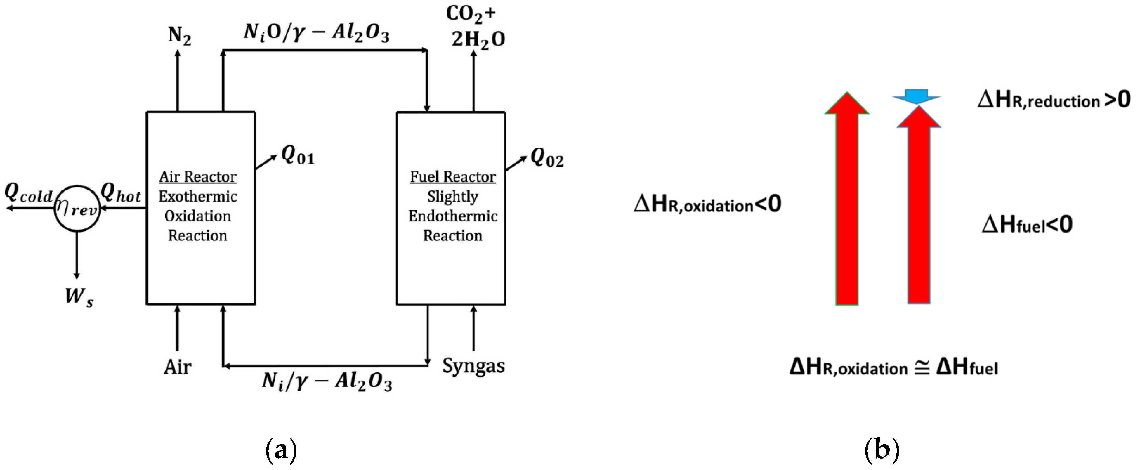
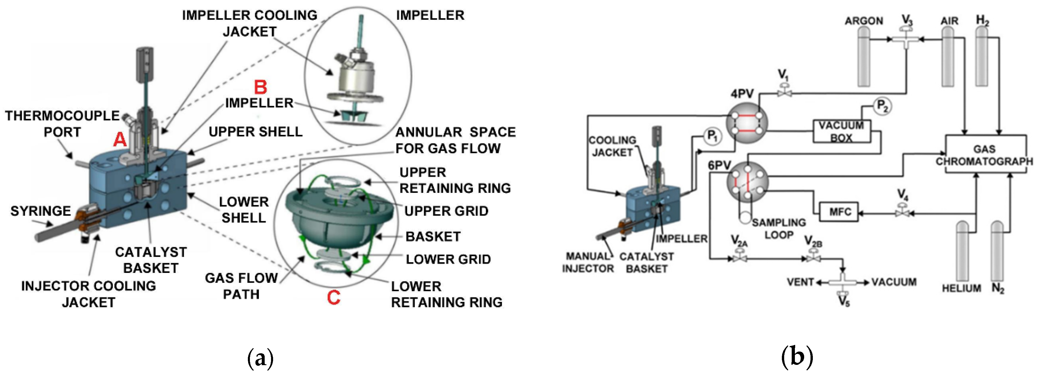

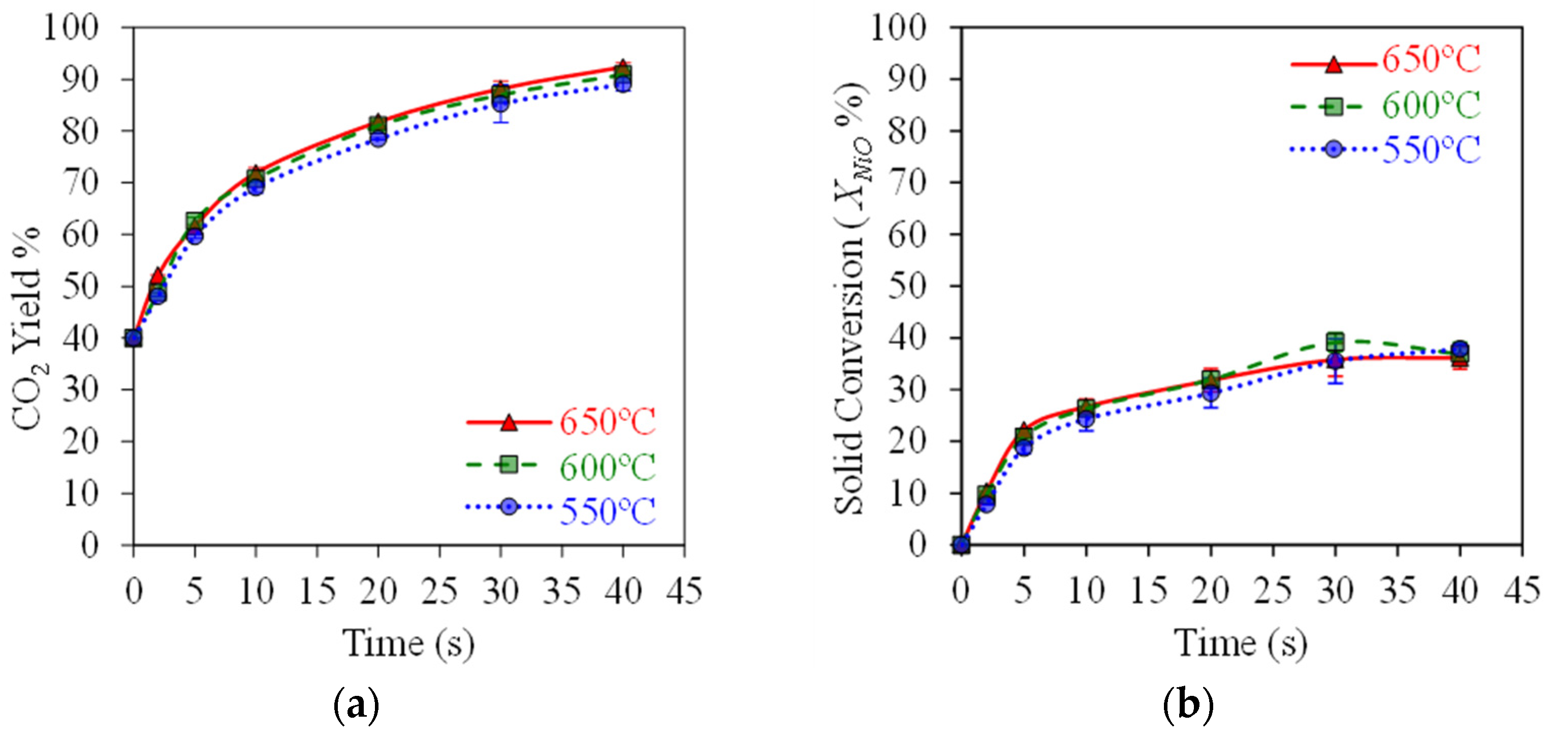
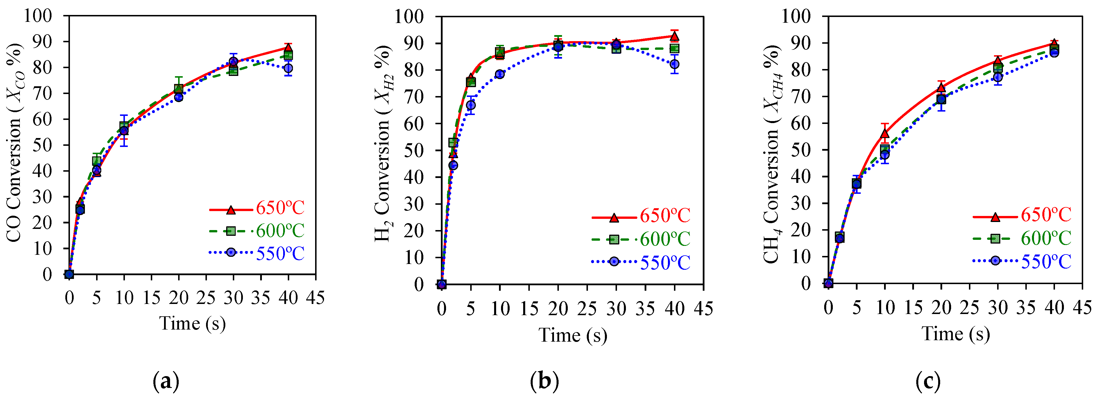

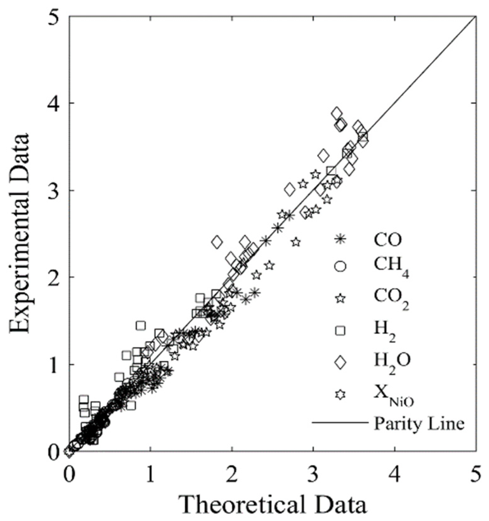
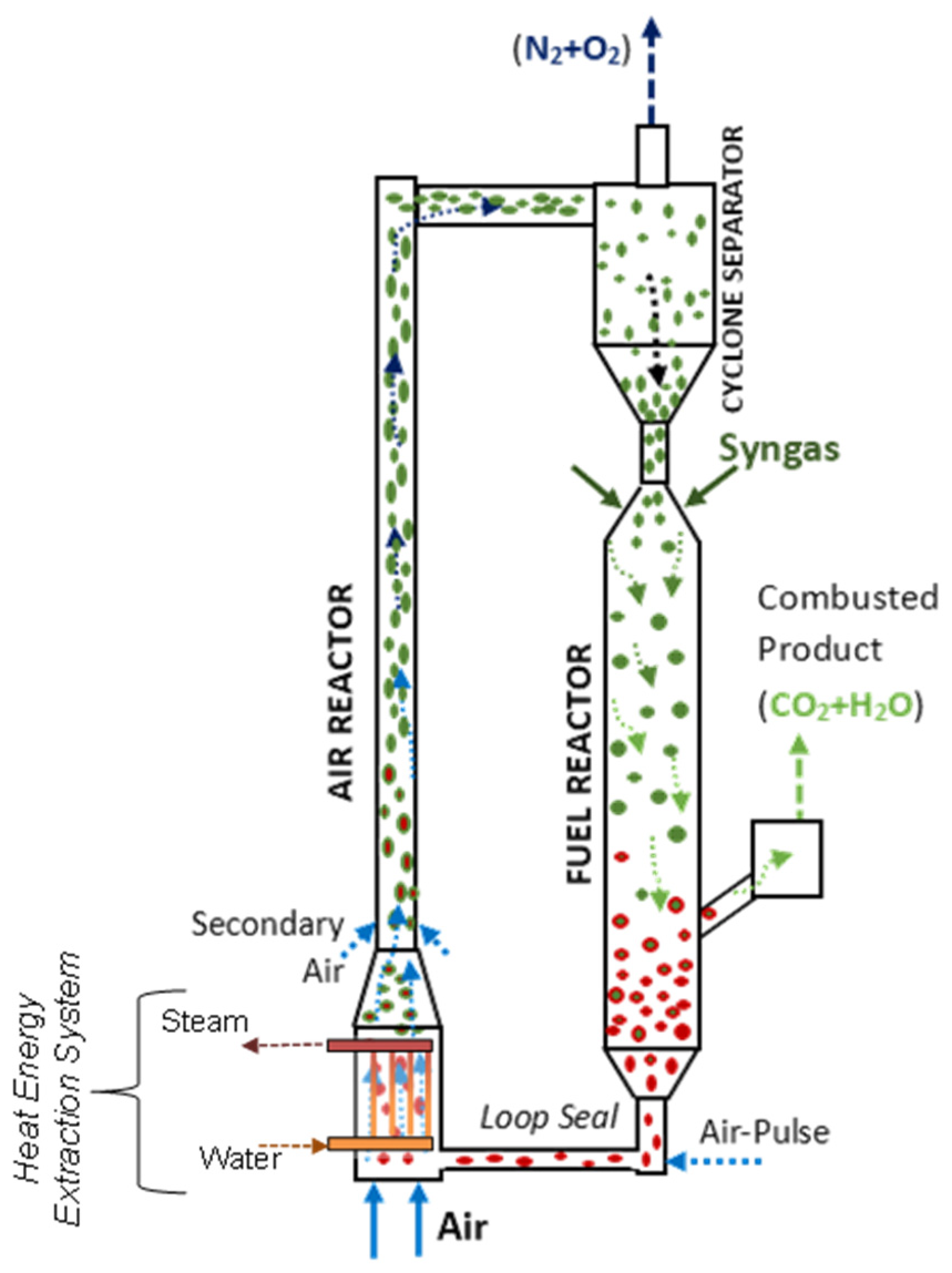
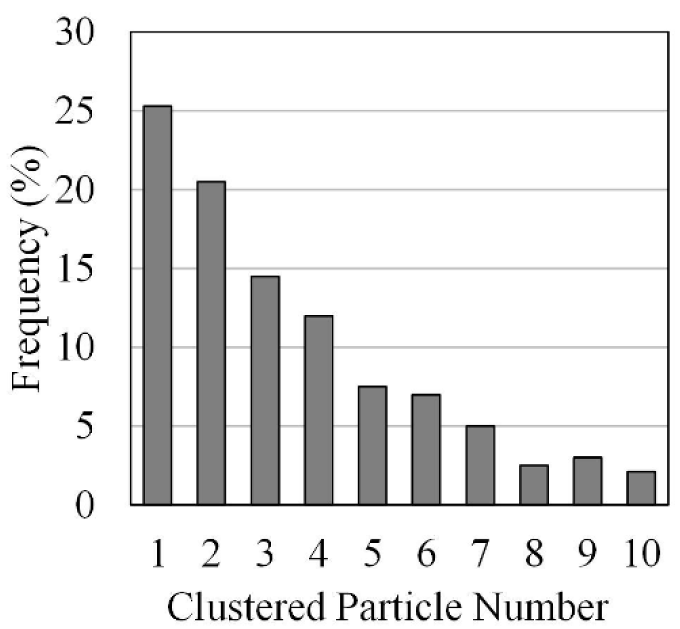
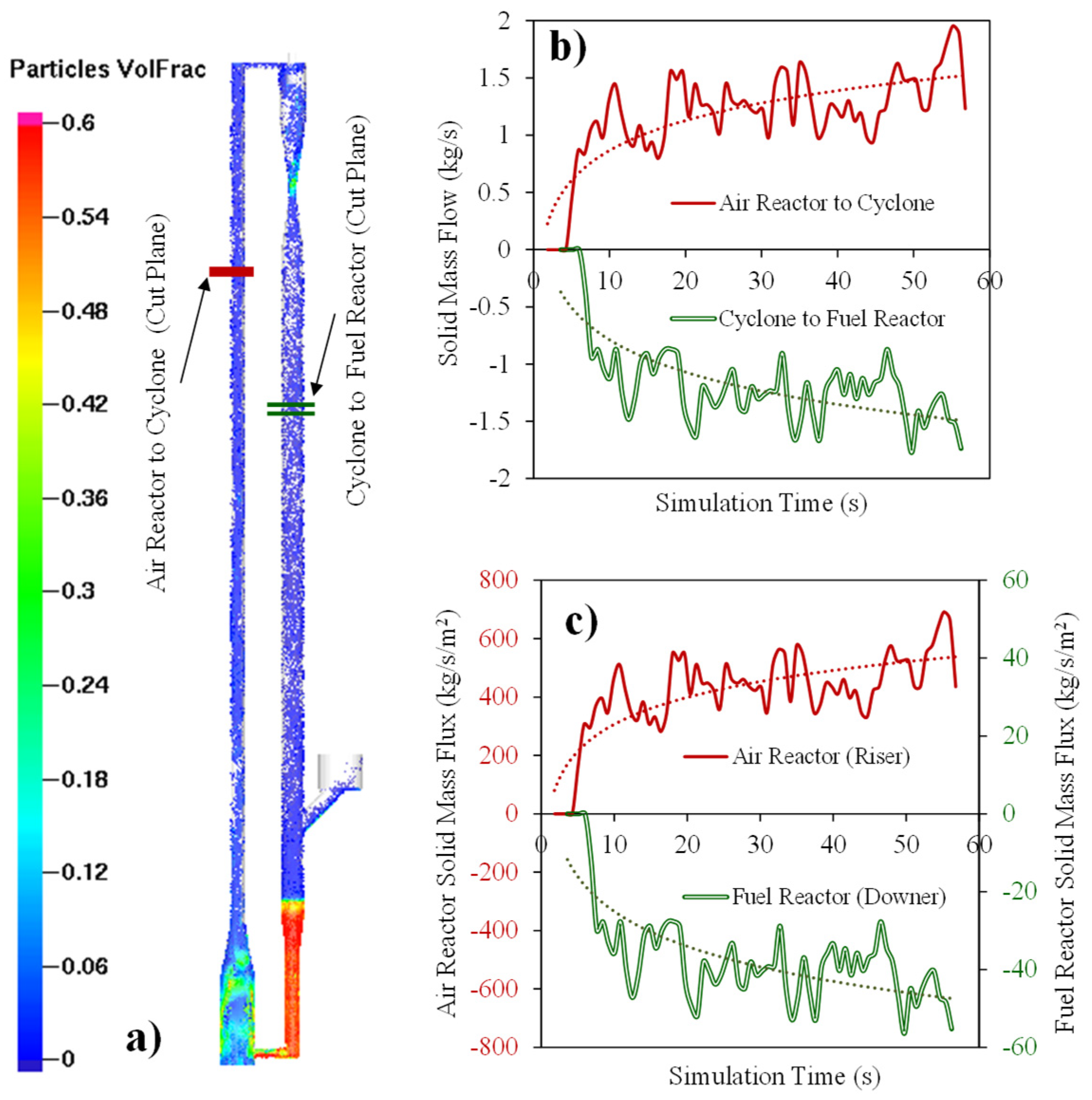
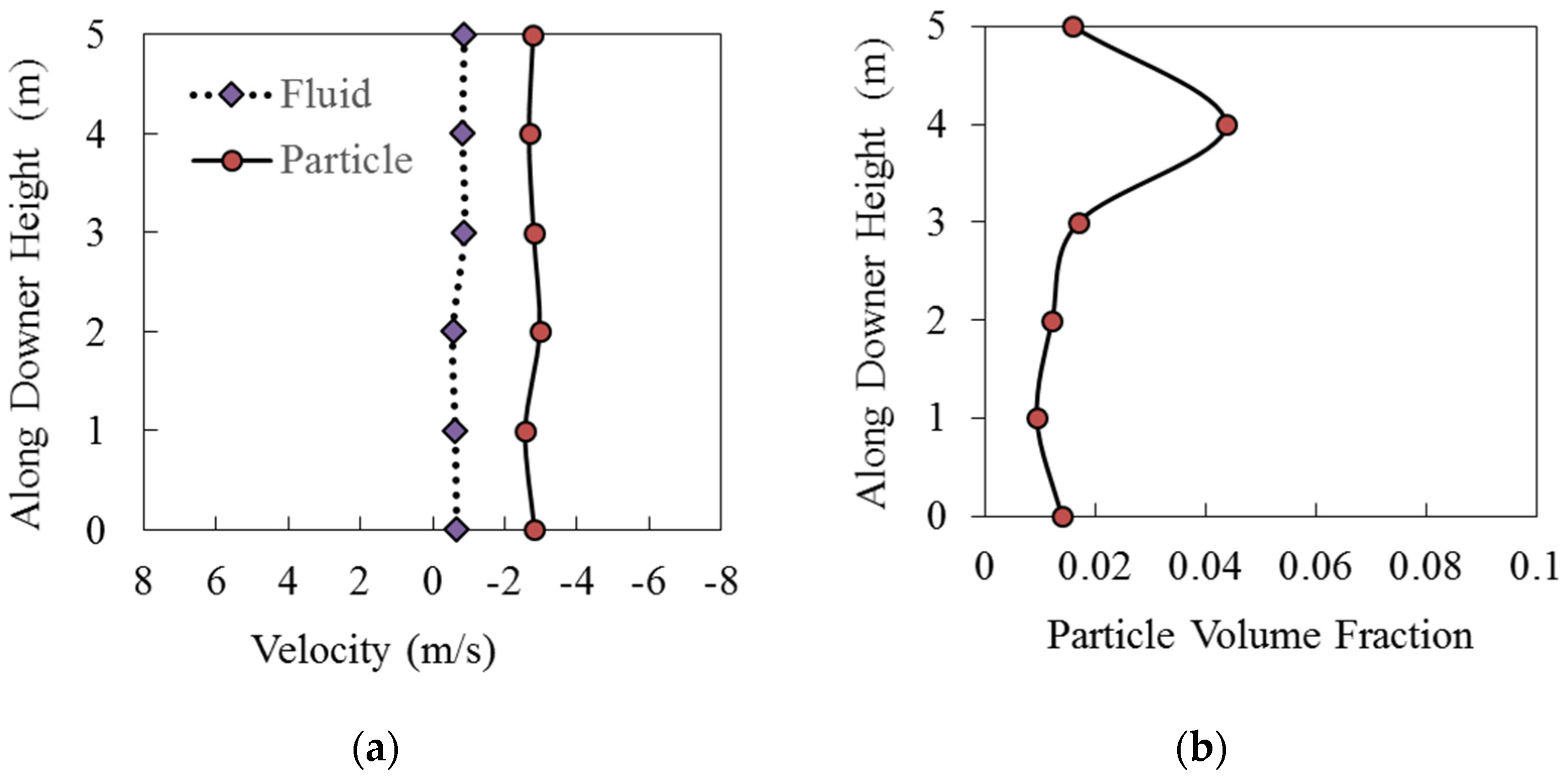
Disclaimer/Publisher’s Note: The statements, opinions and data contained in all publications are solely those of the individual author(s) and contributor(s) and not of MDPI and/or the editor(s). MDPI and/or the editor(s) disclaim responsibility for any injury to people or property resulting from any ideas, methods, instructions or products referred to in the content. |
© 2025 by the authors. Licensee MDPI, Basel, Switzerland. This article is an open access article distributed under the terms and conditions of the Creative Commons Attribution (CC BY) license (https://creativecommons.org/licenses/by/4.0/).