Article

Numerical Study on Hydraulic Fracture Propagation in Coalbed Methane Considering Coal Seam Cleats

1
School of Petroleum and Natural Gas Engineering, Chongqing University of Science and Technology, Chongqing 401331, China
2
PetroChina Southwest Oil and Gas Field Company, Chengdu 610051, China
*
Author to whom correspondence should be addressed.
Processes 2025, 13(4), 1036; https://doi.org/10.3390/pr13041036
Submission received: 17 February 2025 / Revised: 22 March 2025 / Accepted: 27 March 2025 / Published: 31 March 2025
(This article belongs to the Section Energy Systems)

Abstract

:
This study investigated the mechanisms influencing hydraulic fracture propagation under the influence of cleat complex geometries. The study established a 3D-DEM (three-dimensional discrete element method) model for complex fracture propagation, utilizing the discrete element method and incorporating complex cleat geometries. The model simulates the propagation patterns of hydraulic fractures within coal seams. The findings indicate the following: (1) The fracture width within coal seam cleats undergoes significant variations. A quantification method for these variations and a novel concept of cleat-induced fracture deflection angle are proposed. As the cleat angle increases from 0° to 45°, the cleat-induced fracture deflection angle also increases, reaching 17.1°, demonstrating that cleats have a directional inducing effect on hydraulic fracture propagation; (2) injection hole pressure decreases during fracture capture by coal cleats, whereas pressure escalation occurs during penetration through these cleats; (3) a smaller angle between the face cleat orientation and the direction of maximum principal stress results in longer fracture lengths and narrower fracture widths; and (4) higher injection rates augment the fracture width, facilitating the entry of proppants.

1. Introduction

With the decreasing conventional oil and gas resources and the increasing demand for energy, unconventional oil and gas resources, such as coalbed methane, have become a major hotspot in the field of energy exploitation [1]. Coalbed methane reservoirs are characterized by low porosity, low permeability, and low pressure, and geological conditions are complicated [2]. It is difficult to extract and often needs to be modified by hydraulic fracturing to increase production capacity [3]. However, the development of cleats in CBM reservoirs seriously affects the propagation of hydraulic fracture [4]. This fracture characteristic also plays a crucial role in enhancing CBM production [5]. The influence of hydraulic fracture propagation in CBM under the coal cleats is of theoretical and guiding significance for hydraulic fracturing engineering design.
Extensively developed cleats are one of the most significant features of coal seams compared to other types of reservoirs and are also an important factor affecting the effectiveness of coalbed methane development [6]. Through physical experiments, Fan et al. [7] investigated the impact of coal cleats and in situ stresses on the propagation of hydraulic fractures. The results indicated that coal cleats have a significant inducing effect on fractures, which is basically consistent with the conclusions presented in Section 4.1.3 of this paper. However, physical experiments are costly, limited in sample size, prone to large errors in results, and constrained by the degree of cleat development in the materials studied, thus necessitating research tailored to the specific materials available. Many scholars have conducted numerous numerical simulations of coalbed methane based on field geological and engineering data. Li et al. first used Abaqus 6.14 software to analyze fracture reorientation and fracture propagation during fracturing operations in shale reservoirs [8] and then constructed a mathematical model of fracture propagation for CO2 fracturing based on percolation-stress-damage coupling [9], which was used to analyze the influence of different drilling fluid components and reservoir parameters on fracture propagation behavior in low permeability reservoirs. Tan et al. [10] investigated the impact of coal cleats, in situ stress, and construction parameters on the propagation of hydraulic fractures in coal seams. The results indicated that coal cleats and in situ stress play significant roles in determining the direction of fracture propagation. Yang et al. [11] developed a mathematical model of coal cleats on a field scale to investigate the anisotropy of the coupled stress-flow model. The results showed that the anisotropy of coal had a significant effect on the stress distribution, hydraulic conductivity, and damage zones. Wen li et al. [12] used the DFN (Discrete Fracture Network) model to assess the effect of fracture parameters on fluid flow in coal samples from the Yilgarn region of Western Australia. The results showed that the fluid flow increased with the increase in fracture width and stagnation size, but fluctuated with the increase in fracture density. Yu Jing et al. [13], in their study, improved the DFN model by means of coarse-walled fractures with variable width. Their calculated permeability was 30% lower than the conventional DFN, which was more accurate than previous studies. Gao Hui et al. [14] simulated different fracturing processes in coal seams using water as well as supercritical CO2 as fracturing fluids under various stress conditions based on the continuous-discontinuous element method (CDEM). The results showed that fracture development under supercritical CO2 fracturing was more complete, with a large number of fractures and complex morphology. Tao Xiong et al. [15] used Abaqus 6.14 software to establish a three-dimensional finite element model of hydraulic fracturing in deep coal seams, considering seepage-stress-damage coupling. The results show that the hydraulic fracture of injection holes in coal seams is completely restricted from expanding in coal seams, and it is difficult for the hydraulic fracture to pass through the top and bottom plates of coal seams. Zou et al. [16] used cohesive units based on the finite element method to simulate the extended law of hydraulic fractures in CBM and investigated the damage evolution of rocks around hydraulic fractures based on the linear damage theory. Huang Shan et al. [17] investigated the fracture propagation law of coal seams under multi-cluster shot holes based on the discrete element method (DEM) model. The results show that the stress difference has little effect on the fracture area and the number of fractures, but has a significant effect on the fracture density and the subsequent fracture generation efficiency.
The aforementioned scholars have addressed the issue of fracture propagation in coalbed methane fracturing using numerical simulation methods, such as the discrete element method (DEM) and the finite element method (FEM). However, due to the constraint posed by the fracture structure, highly realistic fracture geometries could improve computational accuracy. Although significant progress has been made in studying hydraulic fracture propagation in coal seams—including the “preferential channeling effect” of fractures along cleats and the non-planar fracture morphology controlled by bedding planes and cleats—existing studies have largely overlooked the combined influence of cleat fracture geometry and in situ stress on hydraulic fracture growth. This oversight fails to accurately characterize the impact of densely developed cleat fractures on hydraulic fracture extension during coalbed methane extraction. In this study, we systematically investigate the effects of cleat fracture continuity, spacing, intersection angles, in situ stress differences under varying cleat angles, and injection rates on hydraulic fracture propagation. Our findings reveal that fracture propagation is governed not only by in situ stress but also by cleat-induced stress redistribution. Furthermore, we propose a quantitative method for micro-scale fracture width variation analysis and introduce a novel concept: the cleat-induced fracture deflection angle. This work advances the understanding of fracture-geomechanics interactions in heterogeneous coal reservoirs.

2. Method

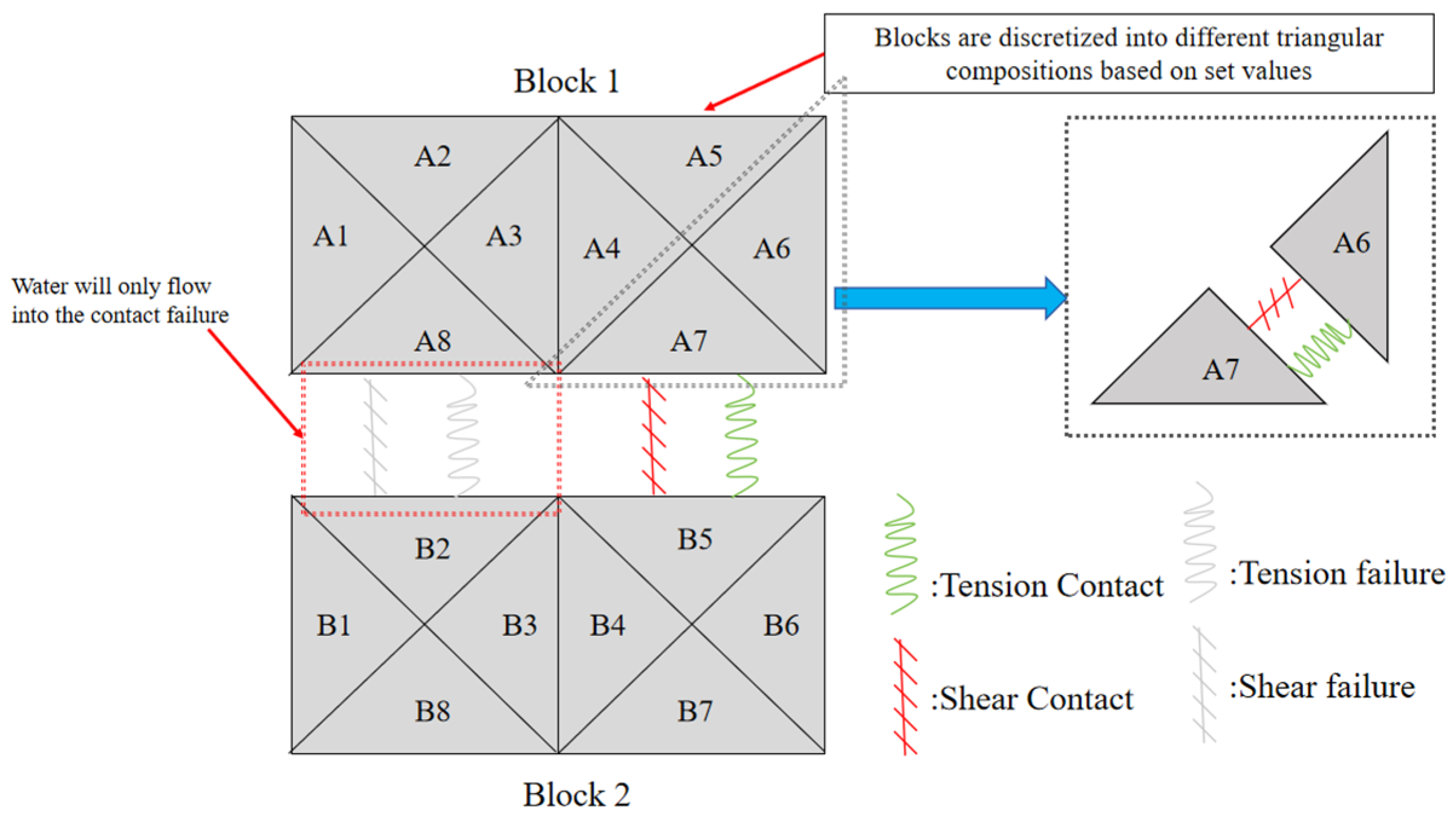
2.1. Mathematical Modeling

The block discrete element method is based on a set value to discretize different blocks into different tetrahedra. The different tetrahedra are connected by tensile and shear contacts, and water injection nodes are assigned among the contacts. In this paper, fluid filtration is not considered, and flowing water only occurs where there is contact failure to express the propagation of hydraulic fractures in the reservoir [18], as shown in Figure 1.
Nodal velocities, displacement, and forces are updated at each time step [19] to conform to Newton’s laws of motion. The intrinsic relationship of the deformed block is expressed as follows:
Δ σ i j e = λ 0 Δ ε v δ ij + 2 μ 0 Δ ε ij
where λ0 and μ0 are Lame’s constants, Δ σ i j e is the elastic increment of the stress increment, Δεv is the increment of the volumetric stress, Δεij is the stress increment, and δij is the Kronecker delta function.
In block discrete elements, a hydraulic fracture is created by failure between contacts. The contact failure has a certain aperture diameter, which is used to represent fracture width in hydraulic fracturing. The disruption of contact exhibits Coulomb slip contact behavior. In the elastic phase, the deformation among the contacts is described by normal and shear relationships. Assuming a normal force in the direction of compression, the normal force increment is as follows:
ΔFn = −KnΔUnAc
The shear force vector increments are as follows:
Δ F i s = K s   Δ U i s A c
where Ac is the contact area and Kn and Ks are the normal and shear stiffness, respectively, ΔUn is the increment of normal displacement, and Δ U i s is the increment of shear displacement.
The maximum normal stress at contact failure is reached through the following:
F m a x n = T max   A c
where F m a x n is the maximum normal stress at contact failure, and Tmax is the tensile strength of the contact.
The maximum shear stress at contact failure is reached through the following:
F m a x s = c A C + F n tan φ
where F m a x s is the maximum shear stress at contact failure, c is the cohesion, and φ is the friction angle.
Equations (2) and (3) are applicable when normal and shear stresses are less than contact tensile and shear strengths. When ΔFn > F m a x n or Δ F i s > F m a x s , the deformation of the node is determined by the deformation of the block, as shown in Equation (1).
Fluid flow in the region of the block where there is a contact failure is in accordance with the Navier–Stokes equation. The contacts are parallel to each other and the fluid is not compressible without taking into account filter losses. The Navier–Stokes equation can be simplified to the Reynolds equation.
q = u 3 Δ P 12 μ l
where u is the cleat aperture diameter, μ is the fluid viscosity, l is the length of the region after the block is discretized, and Δ P is the pressure difference between adjacent regions.
The aperture of the region is denoted as follows:
u = u 0 + Δ U n + Δ U s t a n ψ
where u 0 is the initial pore diameter and ψ is the expansion angle.
The pressure in the region is denoted as follows:
p = p 0 + K w Q Δ t V K w Δ V V 0
where p 0 is the initial pressure, K w is the bulk modulus of the fluid, Q is the sum of flow rate changes in the fluid region, Δ t is the time step of flow rate changes, V 0 is the initial fluid region volume, and V is the new fluid region volume.
The coupled model of stress and fluid is described by the effective stress. The effective stress σ′ is denoted as follows:
σ = σ + α p
where σ is the total stress, α is the Boit coefficient, and p is the internal pressure in the fluid region.
The boundary conditions of the model are defined as follows:
(1)
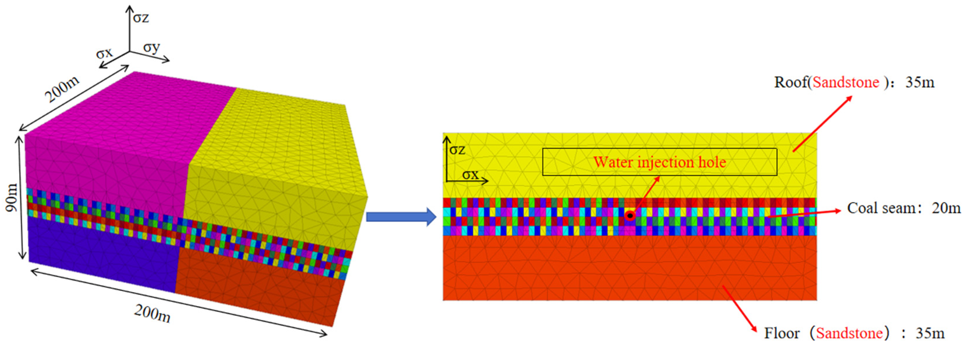
Displacement boundary: Uz = 0 in the Z direction at the bottom of the constrained model to simulate the rigid support of the coal seam floor; the normal displacement constraint is applied to the side of the model, and the displacement Ux = 0 in the X-axis direction and Uy = 0 in the Y-axis direction to avoid rigid body displacement.
(2)
Stress boundary: The vertical stress is calculated according to the formation density. The position of the model centroid is 600 m, the stress gradient is 25 MPa/km, and the horizontal stress is the maximum horizontal principal stress of 15 MPa and the minimum horizontal principal stress of 12 MPa according to the measured data.
(3)
Fluid pressure boundary: The initial pore pressure is 9.8 MPa/km.
Where Uz is the displacement in the z direction, Ux is the displacement in the x direction, Uy is the displacement in the y direction.

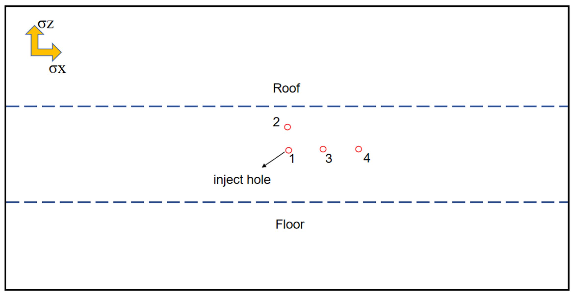
2.2. Geometric Modeling

2.2.1. Three-Dimensional Coalbed Methane Fracture Propagation Modeling with Coal Cleats

The model consists of several blocks, and the cleats are added into the coal seam to divide the coal seam into ‘tofu block’ shape [20]. The length, width, and height of the model is 200 m, 200 m, 90 m, respectively, in which the coal seam is 20 m, where σx is the direction of the maximum principal stress, σy is the direction of the minimum principal stress, and σz is the direction of the vertical stress. The vertical stress is assigned to a simulation model according to the stress gradient. The water injection hole is set at the center of mass of the simulation model. It is shown in Figure 2. The model is divided into different regions by the preset joints, with randomly generated colors used in the software to represent them.
The model is based on the basic data of the Longtan Formation in Guizhou Province to establish a three-dimensional CBM fracture propagation model. The rock and geological parameters are shown in Table 1, the fluid properties are shown in Table 2, and the initial conditions of the model are shown in Table 3.

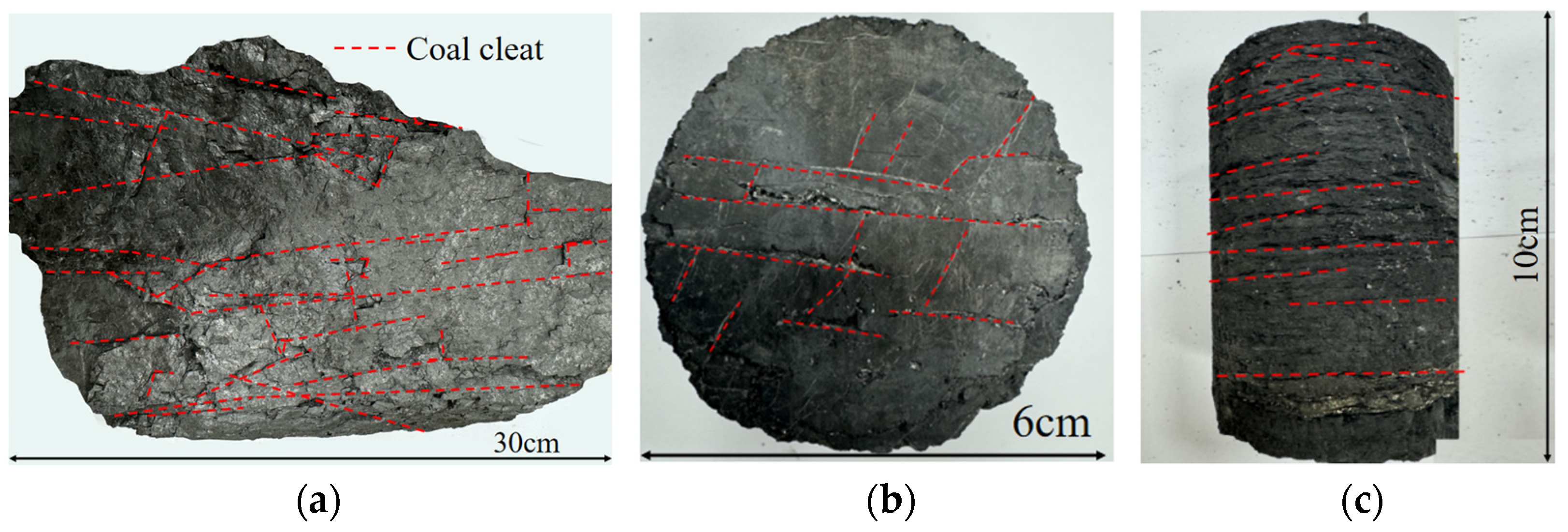
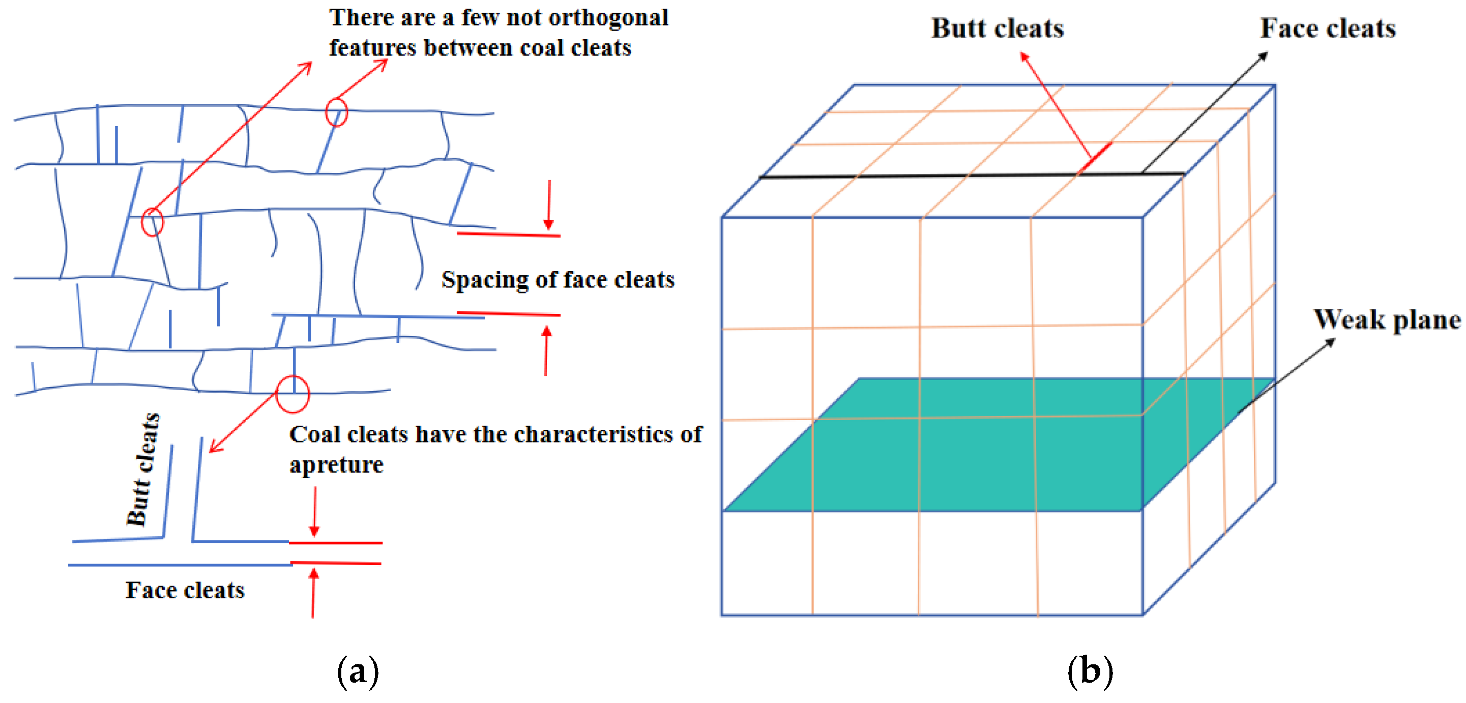
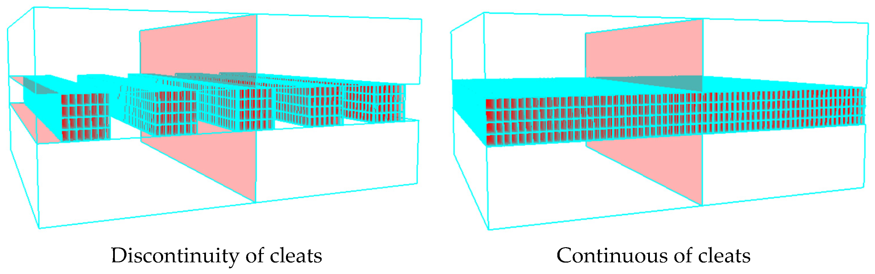
2.2.2. Geometrical Modeling of Coal Cleats
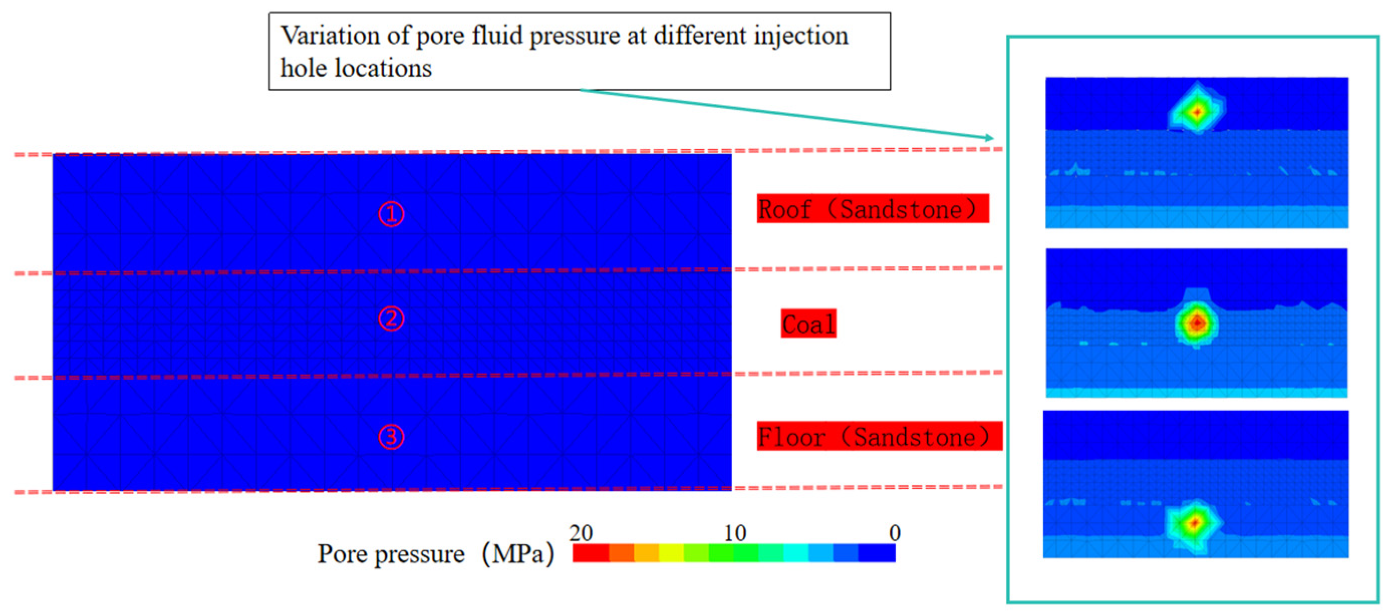
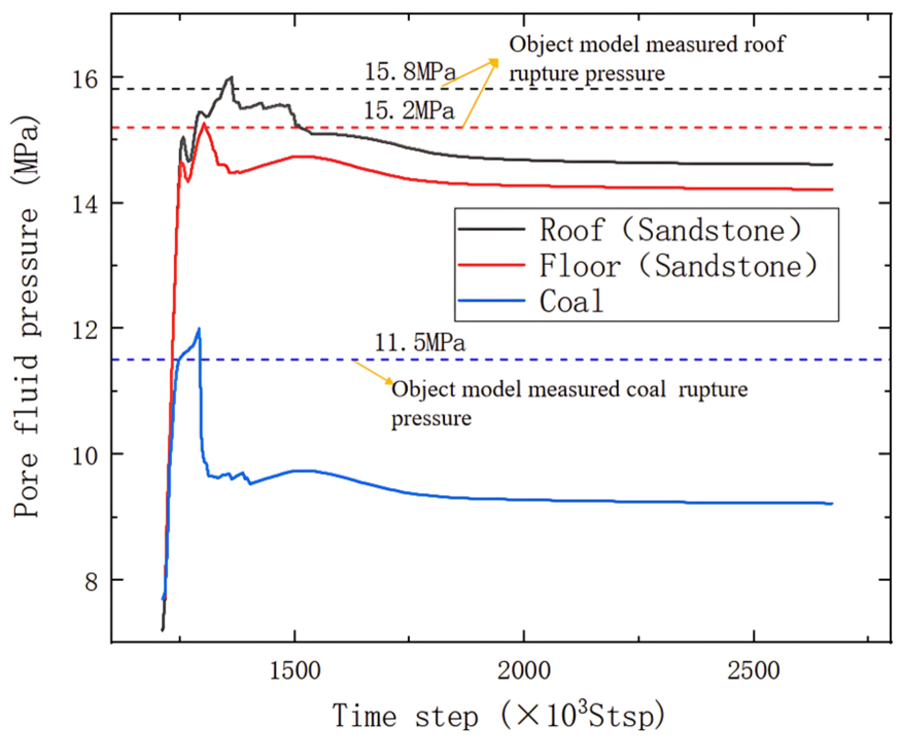
Widely developed coal cleats are one of the most significant features of coal seams compared with other types of reservoirs and are also an important factor affecting the effectiveness of CBM development. Figure 3a shows the diagram of the 9# coal seam of the Longtan Formation in Guizhou Province, China. The depth of the 9# coal seam is 670~690 m, from which it can be seen that there may be a discontinuous distribution between the coal cleats. Figure 3b shows the transverse interface of the core of the 8# coal seam of the Longtan Formation in Guizhou Province, China. The 8# coal seam is at a depth of 655~660 m, which is closer to the 9# coal seam, from which it can be seen that most of the angles of the butt cleats and the face cleats are acute. Figure 3c shows a longitudinal cross-section of the core of the 8# coal seam in the Longtan Formation, Guizhou Province, China. From the two different coal seams, it can be seen that cleats are developed in large quantities in the coal seams, and the density of the cleats in the longitudinal distribution of the face cleats in Figure 3a rock is 0.8 lines/cm, and the density of the cleats in the longitudinal distribution of the face cleats in Figure 3b rock is 0.6 lines/cm. The degree of development of the cleats in the different reservoirs varies a lot, especially in the density of the face cleats, the angle of face cleats with butt cleats, and the continuity of the cleats.
Figure 4a shows the schematic cross-section of a coal block and a diagram of coal cleat modeling. Face cleats are orthogonal in comparison to butt cleats. There is a certain aperture in the coal cleats. The distance between the face and the face cleats is regarded as the spacing of the cleat. There is a big gap between the spacing of cleats and the cleat length in different coal seams, and the cleat length varies from a few millimeters to tens of meters, with a huge range of variation [21]. In addition to the massive development of cleats, the weak-face discontinuous structure also exists in large quantities in the coal seam. In the process of hydraulic fractures extending in the vertical direction of the minimum principal stress, when encountering the weak face, the hydraulic fractures may be captured, penetrated, or the propagation direction may be shifted, and the existence of the weak face will have different degrees of influence on the propagation of hydraulic fractures. The length of butt cleats is typically in the order of centimeters, posing significant challenges in modeling using the discrete element method (DEM) for block modeling. To simplify the model, a schematic diagram of coal seam modeling is shown in Figure 4b. The interaction among the cleats and the weak face in the coal seam divides the coal reservoir into ‘tofu blocks’, which is the basis for the modeling of hydraulic fracture propagation in the coal seams.
The conditions of actual rocks indicate that the properties of face cleats and butt cleats are orthogonal to each other. In this study, the fracture is used to set up the cleat [22]. Fluid can flow in the fracture. The cleat spacing is enlarged. Centered on the model mass point (0, 0, 0), the cleat spacing and cleat number are controlled to divide the coal seam into ‘tofu blocks’. In the top and bottom plates of the coal seam, a vertical fracture propagation surface is prefabricated, as shown in Figure 5, to study the penetration of hydraulic fracturing into the top and bottom plates of the coal seam. The influence of roughness and mechanical anisotropy has not been considered on the surface of coal cleats, and a certain tensile and shear breaking strength is set among the cleats.
The distribution of fractures varies significantly among different coal seams, and some seams exhibit nearly no cleats due to the discontinuous distribution of cleats within the coal [23]. The distribution characteristics of coal seam cleats play a crucial role in the propagation of hydraulic fractures. To investigate the propagation patterns of hydraulic fractures under various coal cleat distribution features, based on the basic model of average cleat distribution shown in Figure 5, three distinct models of fracture continuity distribution are established, as illustrated in Figure 6 below: discontinuous cleat distribution and continuous cleats distribution. Coal cleats possess a certain aperture, with face cleats and butt cleats forming orthogonal features. Of course, the following models represent idealized conditions and are constructed solely for the purpose of facilitating research. These models also aim to explore the propagation patterns of hydraulic fractures in coal seams without cleats versus those with developed cleats. The subsequent research findings further demonstrate that coal seam cleats have a significant impact on the propagation of hydraulic fractures.

3. Model Validation

Taking the Longtan Formation Well H in Guizhou Province, China, as an example, the model is validated based on the available data. The depth of the model’s center of mass is 580 m. The data of mechanical characteristics of the top and bottom plates of the 16# coal in the H well are used as the input parameters of the model, as shown in Table 4. The simulation of the change in pore fluid pressure at the injection holes under different lithological injection locations and the injection hole locations are shown in Figure 7, numbered as hole 1 for the top plate (siltstone), hole 2 for the coal, and hole 3 for the bottom plate (muddy) siltstone, respectively.
The hydraulic fracturing of water injection holes at different locations in different rocks is simulated. The error value between the fracture pressure in different rocks in the model and the results obtained from the physical modeling experiments is <0.04, the error value = (numerical simulation rupture pressure—actual rupture pressure)/actual rupture pressure, and the average of the error values of three different positions. The simulation model can represent the effect of the actual formation. The results are shown in Figure 8 below.

4. Analysis and Discussion of Results

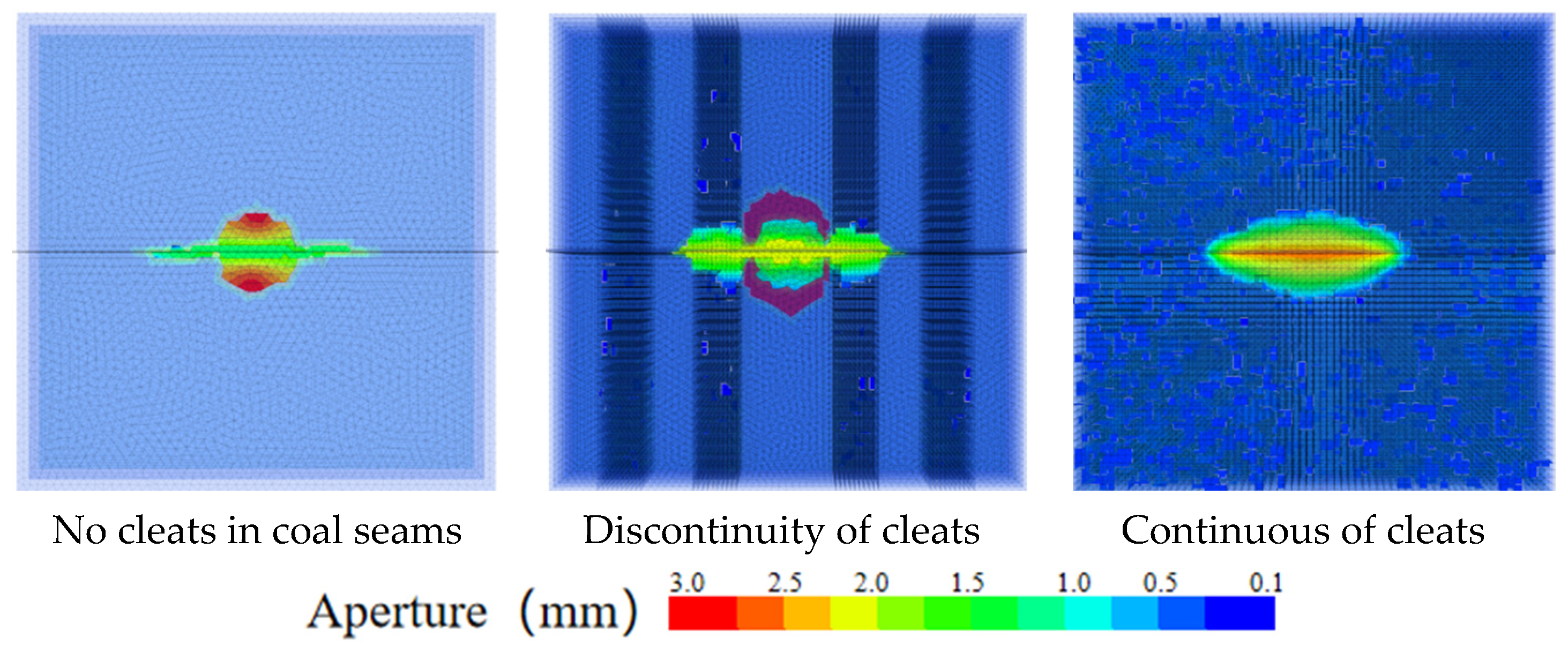
4.1. Effect of Cleats in Coal Seams on Hydraulic Fracture Propagation

The characteristics of cleats in coal seams are the most significant factors distinguishing them from other reservoirs, profoundly influencing the propagation patterns of hydraulic fractures. As mentioned earlier, in the Longtan Formation of Guizhou Province, China, the cleat features of actual coal rock are remarkably distinct. In this subsection, coal seam cleats are studied in three parts: the continuity of the coal seam cleat system, the spacing within the cleat system, and the angle between face cleats and butt cleats as areas of focus.

4.1.1. Continuity of Cleats

Figure 9 illustrates the fracture morphologies under different cleat distribution characteristics in an ideal state, demonstrating that hydraulic fractures are intercepted by areas with cleats. In coal seams with poorly developed cleats, fractures initiate at the water injection borehole and subsequently propagate to form a single main fracture extending toward the distant end. In coal seams with well-developed cleats, fractures initially propagate near the water injection borehole and then form a main fracture extending toward the distant end. After being intercepted by cleats, the main fracture propagates within the cleat system. A schematic diagram is provided in Figure 10.
We wrote code to traverse all nodes with fracture widths, utilized a judgment function, and exported the fracture widths along the line from the centroid of the coal seam profile (water injection hole) to the boundary. Based on these data, we created a chart to analyze the variation in fracture width.
The variation in the fracture aperture under different continuity of cleat is shown in Figure 11. According to the continuity of different cleats, it can be seen that the continuity of a cleat has a great influence on the propagation pattern and the fracture width of hydraulic fractures. Hydraulic fractures are more likely to form complex cleats where the cleats are very developed, and it is also easier to obtain more fluid. The initial aperture of the fracture in the model is set to 1 × 10⁻⁴ m, and the maximum variation in the fracture aperture is set to 3 × 10⁻³ m. It can be seen from the quantitative graph of fracture width under different cleat continuity that the width of the hydraulic fracture has a small range of variation in the absence of cleats, while it varies in the presence of cleats, which also suggests a new design for spreading proppant. When establishing a simulation model using the DEM, the process of discretizing the blocks involves a certain degree of randoness, such as slight variations in the number and locations of the discretized solution domains. These random factors can lead to a certain degree of asymmetry in the hydraulic fractures observed in the simulation results.
The stimulated reservoir volume (SRV) in coal reservoirs is a crucial indicator for evaluating the effectiveness of hydraulic fracturing. In the 3dec trial version software based on the discrete element method (DEM) used, calculating the SRV is difficult. By using the referencing method used by other scholars [24] to calculate SRV and the model with a water injection rate of 16 m3/min as an example, as shown in Figure 12, it can be observed from the 3D fracture morphology map that fractures have difficulty penetrating through the roof and floor. Under the continuous distribution of cleats, hydraulic fractures are fully extended in the coal seam. In this block, the vertical stress is greater than the minimum principal stress. The hydraulic fractures should be dominated by vertical fractures, and the fractures can be fully extended in the coal seam. SRV = x-axis and y-axis section fracture width change area * coal reservoir height (20 m).
Utilizing the open-source public image processing software ImageJ 1.53t, we calculated the modified area of fractures along the x-axis and y-axis, as well as the length and width of hydraulic fractures. CIPOLLA et al. [25] proposed a theory with the fracture complexity index (Ifc) to characterize fracture complexity. The fracture complexity index is abbreviated as Ifc, which is the ratio of fracture network width to length in the microseismic fracture detection map. For example, during the continuous distribution of cleats in coal seams, the water injection rate is 16 m3/min. First of all, the image length is calibrated to the actual reservoir length of 200 m, and the required area of measurement and length are selected. It can be calculated that the reservoir reconstruction volume (SRV) under this condition is V = S (reservoir reconstruction area) × H (reservoir reconstruction height) = 2050 m2 × 20 m = 41,000 m3, and the fracture complexity index (Ifc) = fracture network width/fracture network length = 37.3 m/94.7 m = 2.54. The higher the ratio of the fracture width to length is, the higher the fracture complexity is. On the contrary, a lower ratio may indicate that the fracture is more slender and less likely to produce complex seam networks, and the complexity is lower.

4.1.2. The Influence of Spacing of the Cleat System

According to the analysis of the influence of cleat continuity on the propagation of hydraulic fracture in the coal reservoir, it is found that cleat continuity has a great influence on the fracture length, fracture width, and reservoir reconstruction area. Models with four different cleat densities of 5 m, 10 m, 15 m, and 20 m were established. The propagation of hydraulic fractures in the coal seam under different cleat spacing is analyzed. Figure 13 shows the fracture morphology of 3D with different spacings of coal cleat systems, and Figure 14 shows the morphology of the x-axis and y-axis of the profile fracture width with different spacings of coal cleat systems. The water injection holes are on the cleat when the spacing of the coal cleat system is 5 m and 20 m. From Figure 14, it can be seen that when the water injection holes are on the cleat, the hydraulic fracture preferentially extends along the cleat, and there is a favorable reforming area at the cleat, and the hydraulic fractures show “cross” propagation, and the coal cleats system has an inducing effect on the direction of the propagation of the hydraulic fracture. The hydraulic fracture is fully extended in the first cleats encountered with a certain amount of fluid. When the spacing of the coal cleat system is 10 m and 15 m, the water injection hole is in the middle of the cleat system, and the hydraulic fracture can be fully extended in the two nearby cleat systems, and the hydraulic fracture is difficult to be fully extended outside the cleats. When the spacing of the coal cleat system reaches 20 m, the fracture length is the longest, and the area will hardly achieve a favorable stimulated volume far away from the water injection hole.
Based on the variation data of fracture width, as shown in Figure 15, when the fracture spacing is 5 m, 10 m, 15 m, and 20 m, the regions where the fracture width changes uniformly and within a narrow range have lengths that coincidentally match these spacing values. At locations with cleats, the large variation in the fracture width is unfavorable for the placement of proppant in fracturing operations, necessitating a redesign of the proppant placement scheme. Due to the highly developed cleats in coal seams, the proppant placement scheme may differ significantly from that used in conventional tight sandstone or shale formations.
Under a fluid injection rate of 16 m3/min, hydraulic fractures generally do not penetrate through the roof and floor, regardless of the spacing of coal cleats. The spacing of the coal cutting system has a nonlinear effect on the SRVof the reservoir. The reason for this change is that we ignore the influence of the perforation position on the srv. It can be seen from Figure 14 that when the perforation position happens not to be on the cutting system, the coal seam without cutting greatly inhibits the SRV. When hydraulic fracturing is performed, it is recommended that the perforation location is in the cutting of a large number of developed coal seams, which may obtain a better SRV, as illustrated in Figure 16b. However, it significantly affects the fracture width values. As the spacing between cleat systems increases, the average fracture width decreases from 1.1 × 10⁻³ m to 0.48 × 10⁻³ m. This is because as the spacing between cleats system widens, the density of cleats in the model decreases, resulting in narrower fracture widths in coal seams with no cleat system or poorly developed cleats compared to those with abundantly developed cleats. According to the results shown in Figure 16a, the spacing of coal cleats has insignificant effects on the fracture width, the fracture length, and the fracture complexity index.

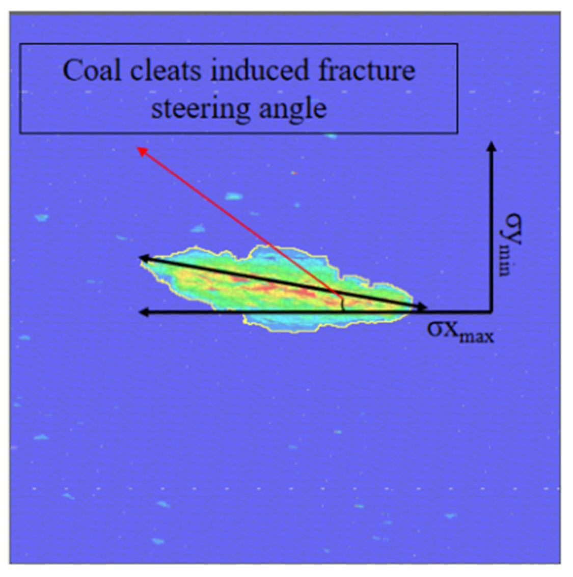
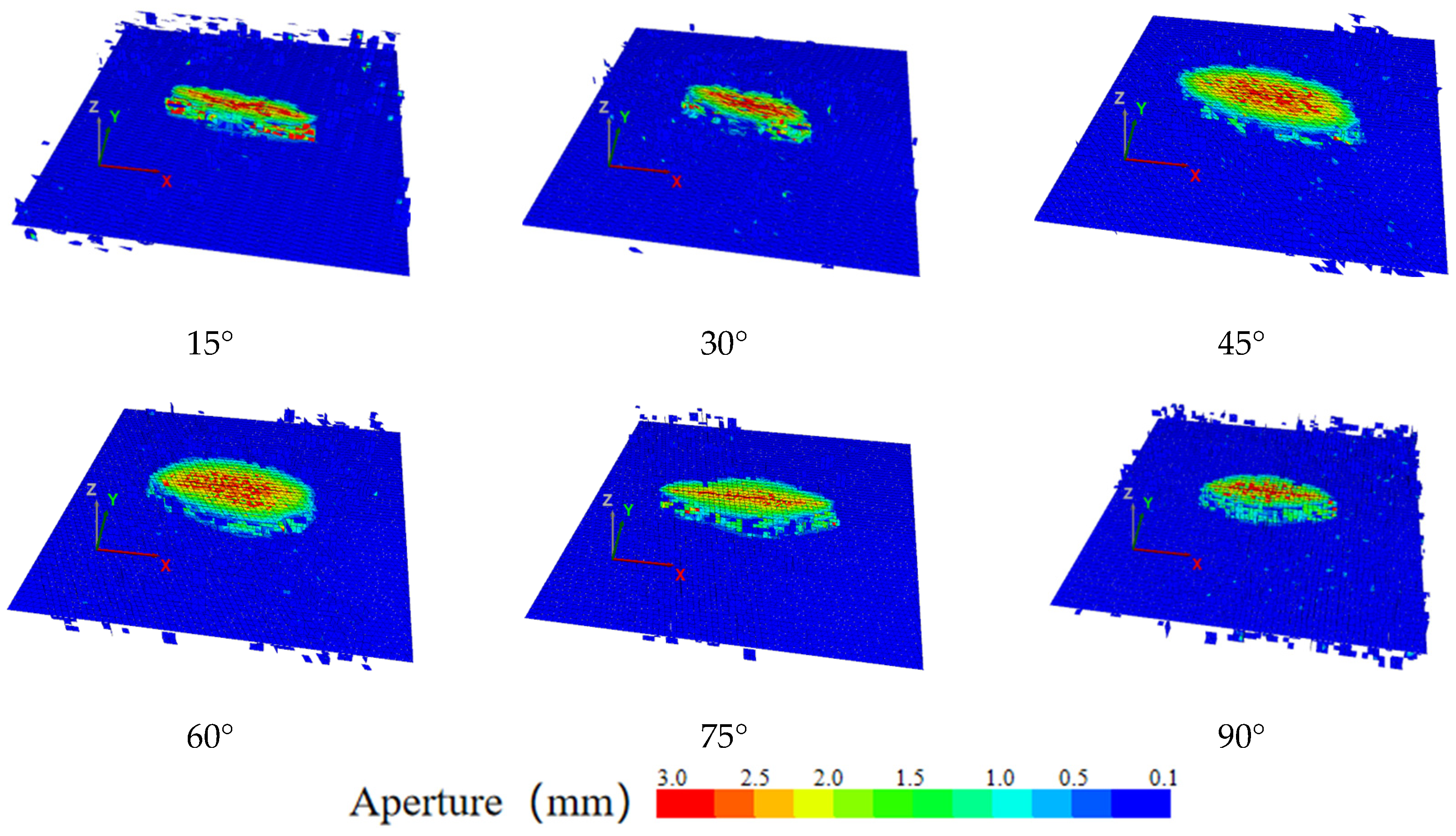
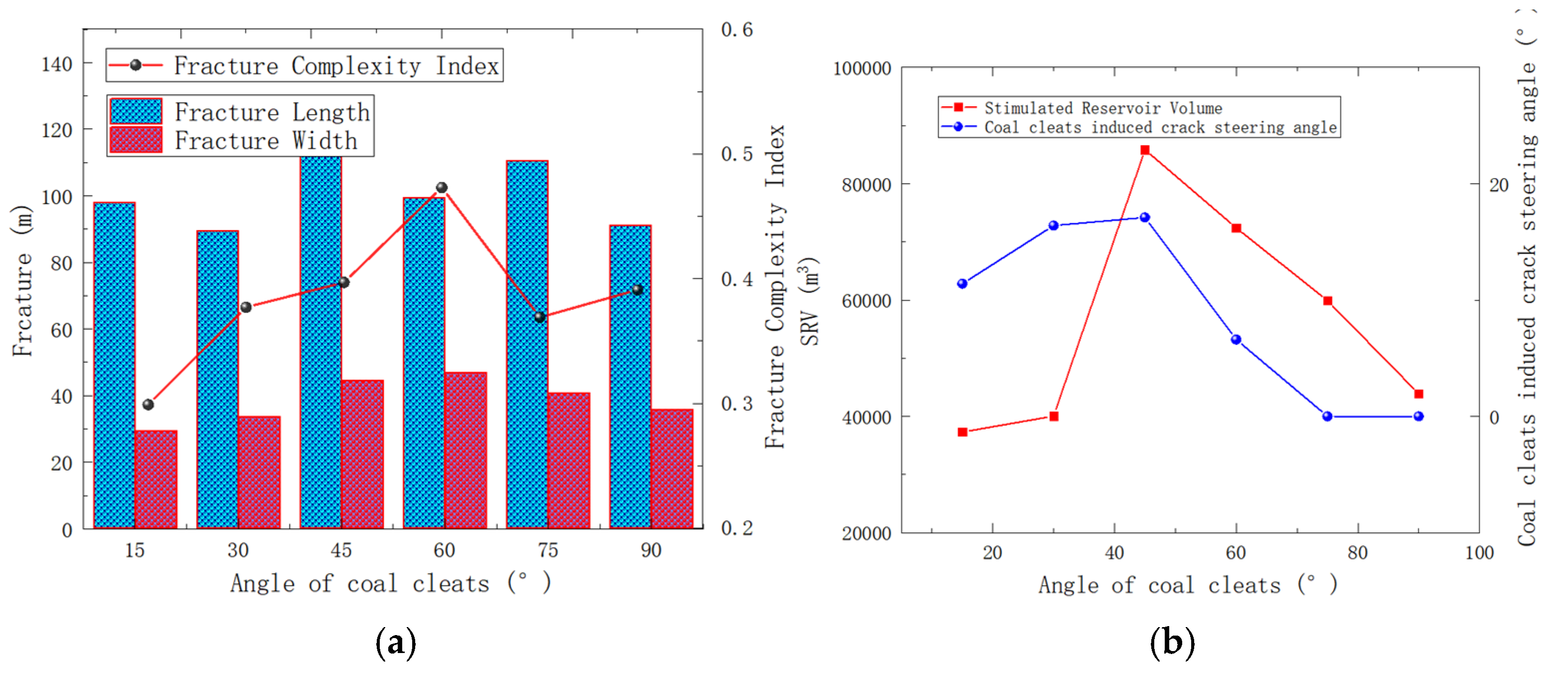
4.1.3. The Influence of Angle Face Cleat and Butt Cleat

Based on the observation of the 9# coal seam of the Longtan Formation in Guizhou Province, it is found that most of the angles between the butt cleat and the face cleat show orthogonal characteristics, but there are a few face cleats and butt cleats with acute angles. The effect of different cleat angles on the propagation of hydraulic fractures is investigated. The hydraulic fracture propagation models of coal reservoirs with cleat angles of 15°, 30°, 45°, 60°, 75°, and 90° were established.
Based on the established hydraulic fracture propagation model of coal reservoir, the hydraulic fracture propagation in the reservoir was simulated under the coal cleat angles of 15°, 30°, 45°, 60°, 75°, and 90°. Figure 17 shows the morphology of the X-axis and Y-axis profiles with different coal cleat angles. As seen in Figure 17, the extended direction of the hydraulic fracture is also closely related to the angle of the cleat. Although the hydraulic fracture extends along the maximum principal stress, it will also be deflected with the change in the angle of the cleats. When the angle of the cleats is greater than 45°, the hydraulic fracture modifies the area in the X-axis and Y-axis, and changes from a long and narrow shape to an elliptical shape. When a large number of regular face cleats have a characteristic angle with a direction of maximum principal stress, the direction of fracture propagation will be induced to turn by the direction of face cleats. Figure 18 shows the schematic diagram of fracture diversion induced by cleats. A new concept is introduced here. When the direction of the face cleat does not coincide with the direction of the maximum principal stress, the angle between the longest fracture length direction and the direction of the maximum principal stress of the hydraulic fracture extending in the profile of horizontal to the ground surface is defined as the steering angle of the fracture induced by the direction of the face cleat. The exact meaning is shown in Figure 19. The purpose of introducing this concept is to quantitatively study the inducing effect of face cleat on the propagation direction of hydraulic fractures.
Figure 20 shows a graph of 3D fracture morphology for different cleat angles. Figure 21a shows plots of fracture length, width, and Ifc data for different cleat angles. Figure 21b shows the data plots of SRV and the steering angle of the cleat-induced fracture for different cleat angles. The direction of the butt cleat is parallel to the maximum principal stress, and for the convenience of the study, all the butt cleat is continuously distributed here. When the angle between face cleat and butt cleat is 15°, the hydraulic fracture is severely induced by the face cleat, and the propagation direction is 11.4° from the direction of maximum principal stress. As the angle between the face cleat and the maximum principal stress increases to 45°, the steering angle of the cleat-induced fracture also increases to 17.1°. The influence of the face cleat on the direction of fracture propagation is increasing. When the angle between the face cleat and the butt cleat is 60°; although the steering angle of the cleat-induced fracture decreases to 6.6°, it can be seen from the graphs of X-axis and Y-axis changes in the width of the fracture at 60° that the fracture is still induced by the face cleat. When the angle between the face cleat and the butt cleat increases from 75° to 90°, the face cleat gradually loses their inducing effect on hydraulic fractures. Here, since the butt cleat is considered a continuous distribution, the butt cleat also has a competitive effect on the direction of fracture propagation. As the angle between the face cleat and the butt cleat keeps expanding, the overall fracture width shows a tendency to propagate, and the fracture complexity index is the most complex when the angle is 60°. It can be inferred that when the direction of the face cleat in the coal seam is parallel to the direction of the maximum principal stress, the hydraulic fracture complexity is poor, and it is easy to form a modified area with a narrow shape.

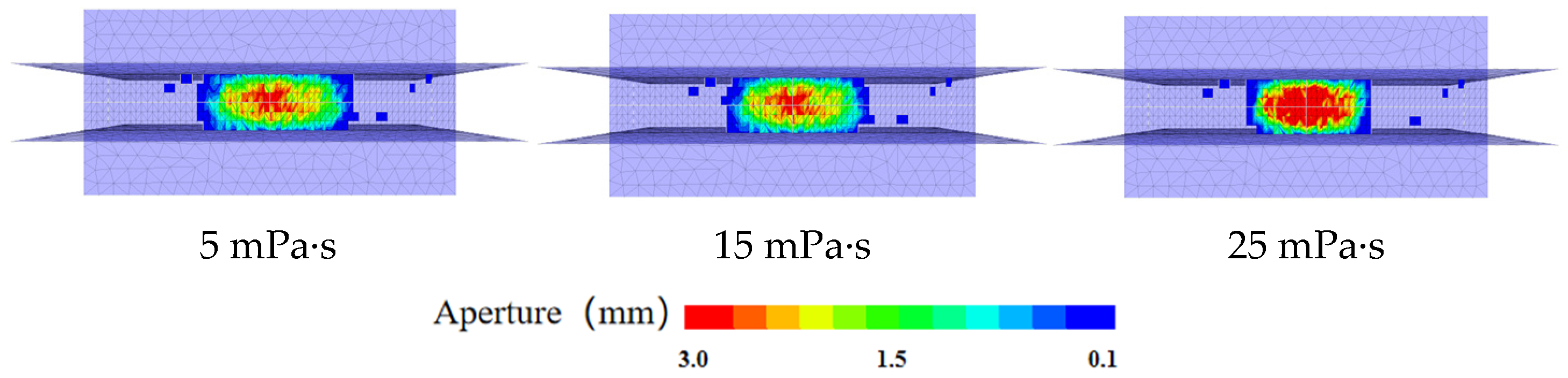
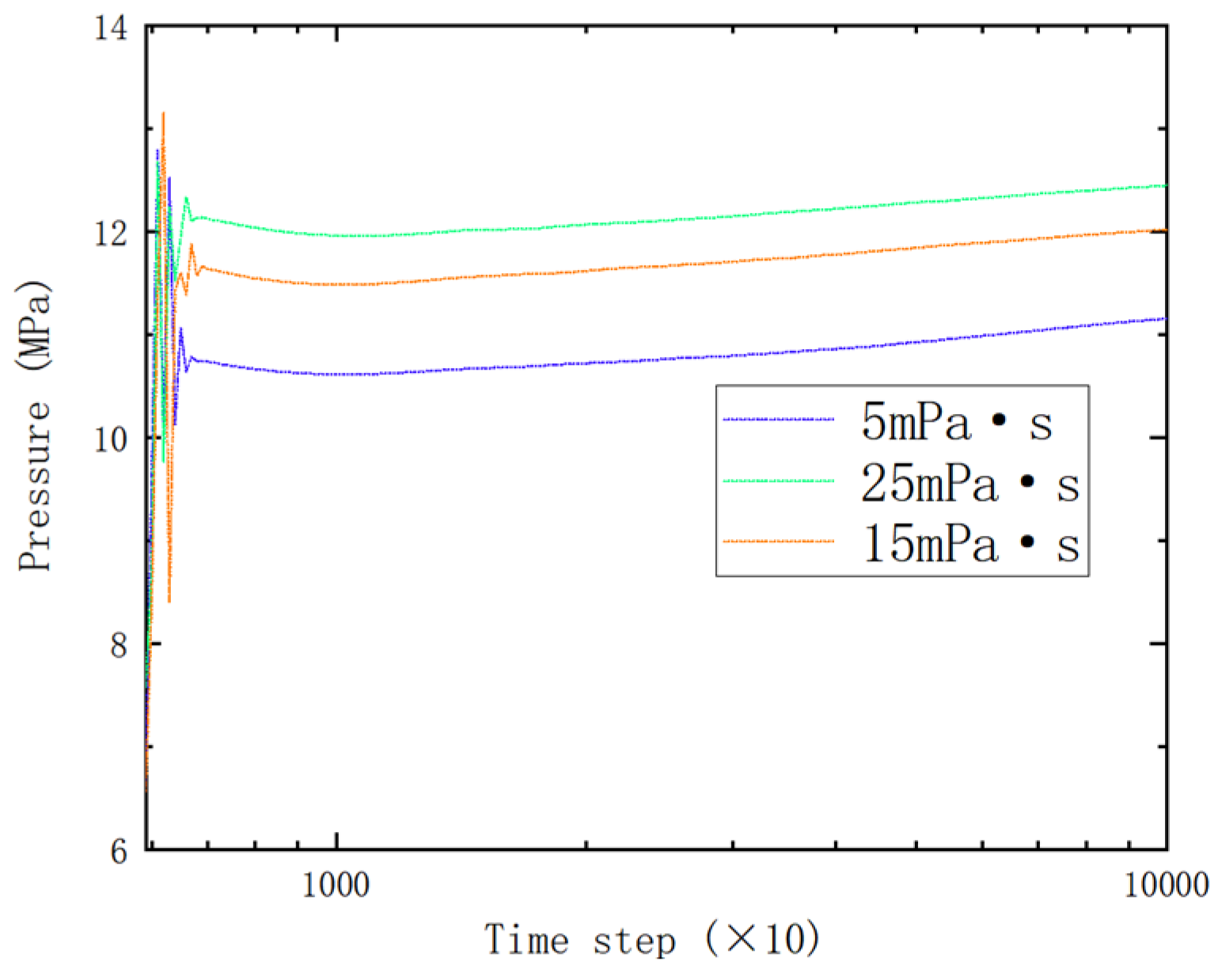
4.2. Effect of Different Viscosity of Liquid in Coal Seams on Hydraulic Fracture Propagation

The viscosity of fracturing fluid plays a critical role in fracture propagation. This section investigates the effects of three fluid viscosities (5 mPa·s, 15 mPa·s, and 25 mPa·s) on hydraulic fracture propagation. As shown in Figure 22, pore pressure variations were monitored at four locations: Point 1 (injection hole), Point 2 (5 m from Point 1), Point 3 (10 m from Point 1), and Point 4 (10 m from Point 3). Figure 23 displays the pore pressure profiles at different monitoring points under 5 mPa·s viscosity. The data analysis reveals that during the initial water injection phase, significant fluctuations in pore pressure were observed at the injection borehole (Point 1) within the cleated coal formation. This phenomenon is attributed to the interception of propagating hydraulic fractures by natural cleats, which temporarily reduces the fracture propagation pressure. The pressure subsequently increased again as fractures penetrated through the cleat systems. With continued injection, hydraulic fractures progressively extended toward Points 2, 3, and 4, resulting in sustained pore pressure increases at these monitoring locations. Notably, the magnitude of pore pressure exhibited an inverse correlation with distance from the injection point: Points 2, 3, and 4 demonstrated sequentially lower pressure values corresponding to their increasing separation from the injection hole.
Figure 24 illustrates fracture morphology under different fluid viscosities. Figure 25 shows the pressure data of different viscosities. The data demonstrate that as viscosity increases, fracture propagation length decreases while fracture width progressively enlarges. For all three viscosity conditions, the pore pressure at Point 1 exhibited its initial pressure drop around 12 MPa. During early injection stages, coal cleat interference consistently induced significant pressure fluctuations at Point 1 across all viscosity scenarios. As fluid viscosity elevated, sustained pore pressure increases at Point 1 were observed, aligning with the viscosity–pressure relationship derived from the Navier–Stokes equations. From a field fracturing perspective, this viscosity-dependent pressure behavior indicates that higher-viscosity fracturing fluids will require elevated operational pumping pressures during stimulation treatments.

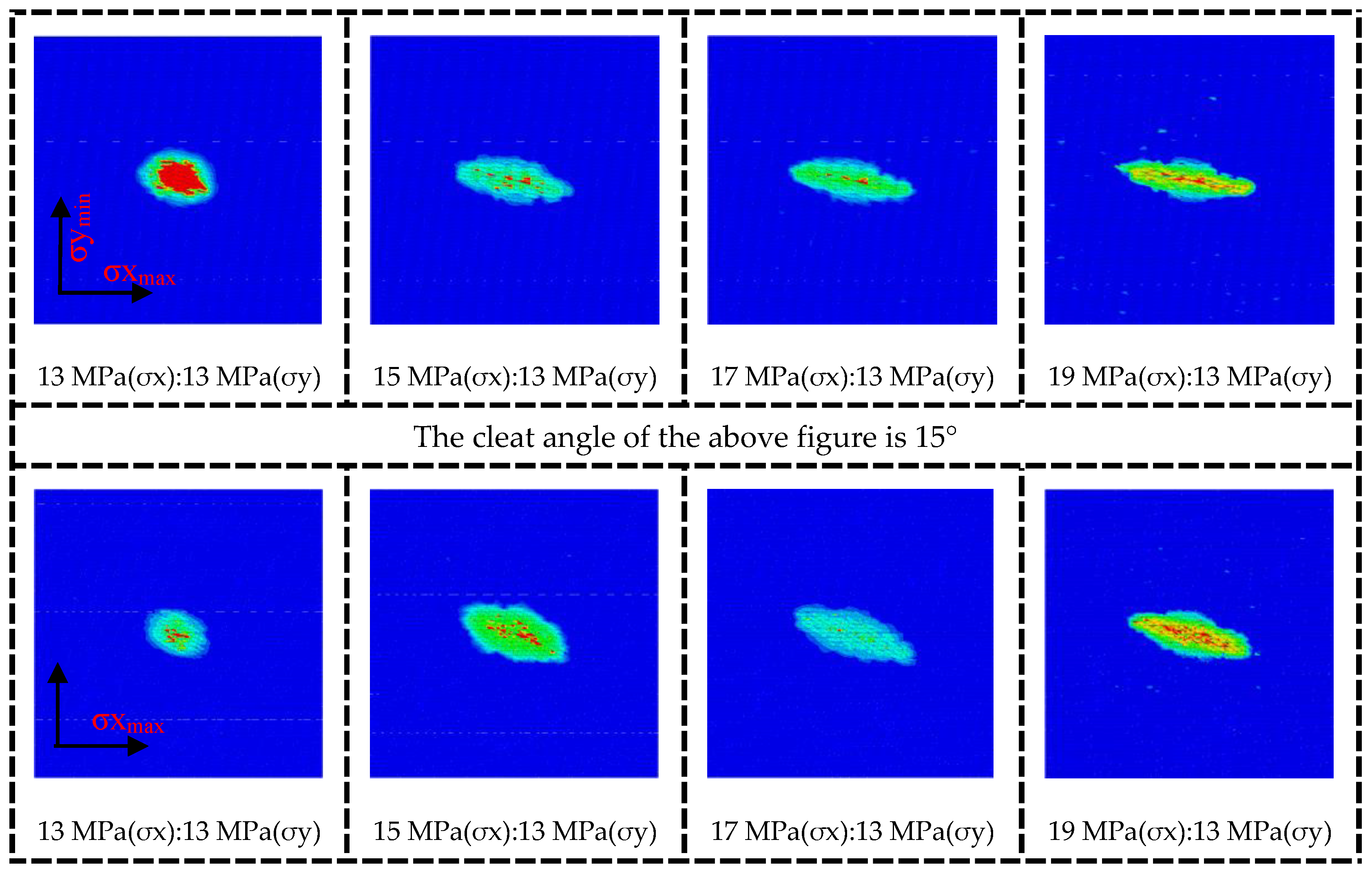
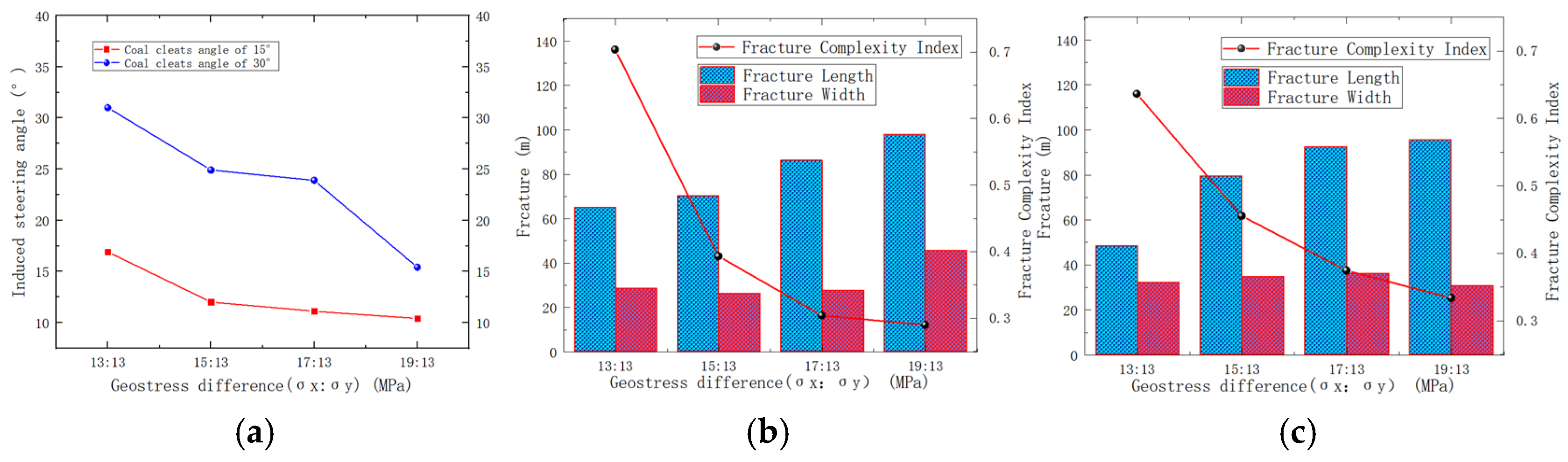
4.3. Effect of Geostress Difference in Coal Seams on Hydraulic Fracture Propagation

According to the study of the extended law of hydraulic fractures in coal seams based on the angle of cleat, it is found that the angle of cleat has an important influence on the propagation direction of hydraulic fractures. In conventional fracture mechanics theory [26], hydraulic fractures extend along the direction of maximum horizontal principal stress. In order to investigate the effect of geostress difference and angle of cleats on the propagation direction of hydraulic fractures, the geostress parameters were changed under the model of 15° and 30° cleats, and the effects of geostress difference and angle of cleats on the fracture propagation direction were examined. Figure 26 shows the morphology of the fracture width.
Under the same geostress difference, the propagation direction of hydraulic fractures is influenced by face cleats and butt cleats. When the magnitude of the maximum principal stress is set from 13 MPa to 19 MPa, with an increasing geostress difference, the steering angle of cleat-induced fracture decreases from 17° to 11° at a cleat angle of 15°, and from 31° to 15° at a cleat angle of 30°. With the cleat angle remaining constant, the geostress difference has a significant impact on the fracture propagation direction. The steering angle of the cleat-induced fracture is smaller than the angle between the face cleat and the maximum principal stress. This leads to the conjecture that the influence of the maximum principal stress on the fracture propagation direction is greater than the inducing effect of the face cleat. As the geostress difference increases, the fracture gradually propagates along the direction of the maximum principal stress, which also verifies the correctness of the model. When setting the maximum principal stress from 13 MPa to 19 MPa, at a cleat angle is 15°, the fracture length increases by 50% from 65 m to 98 m, while the fracture width decreases by 42% from 49 m to 28 m. The fracture length increases by 90% from 50 m to 95 m when the angle of the cleat is 30°. With the continuous increase in the geostress difference, the fracture length gradually decreases, the fracture width gradually increases, and the fracture complexity index decreases. The smaller the angle between the strike of the face cleat and the direction of the maximum principal stress is, the longer the fracture length and the smaller the fracture width are. Figure 27a is a data diagram of the steering angle of cleat-induced fracture under the influence of cleat angle and geostress difference. Figure 27b is a data diagram depicting changes in the fracture length, width, and Ihc at the cleat angle of 15° under geostress difference. Figure 27c is a data diagram depicting changes in the fracture length, width, and Ifc at the cleat angle of 30° under different geostress differences.

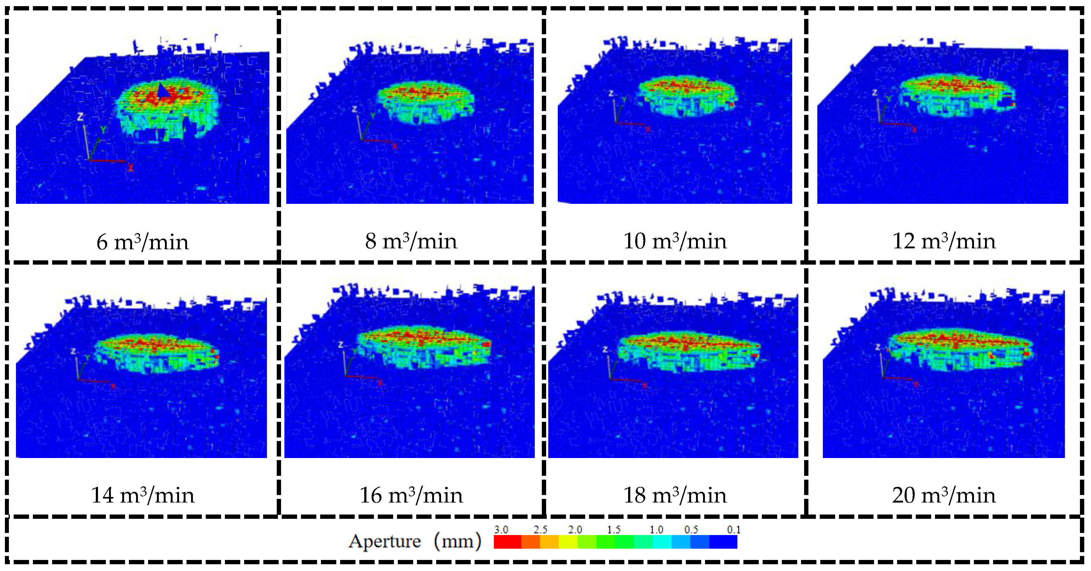
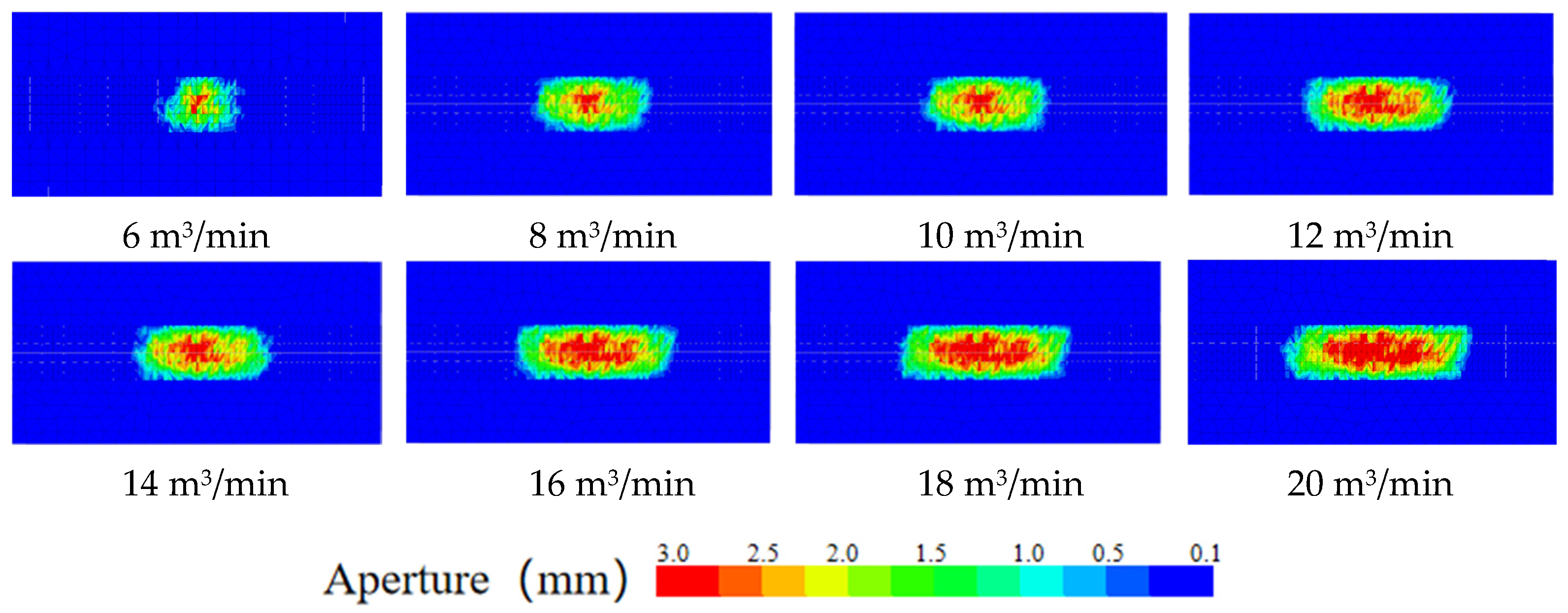
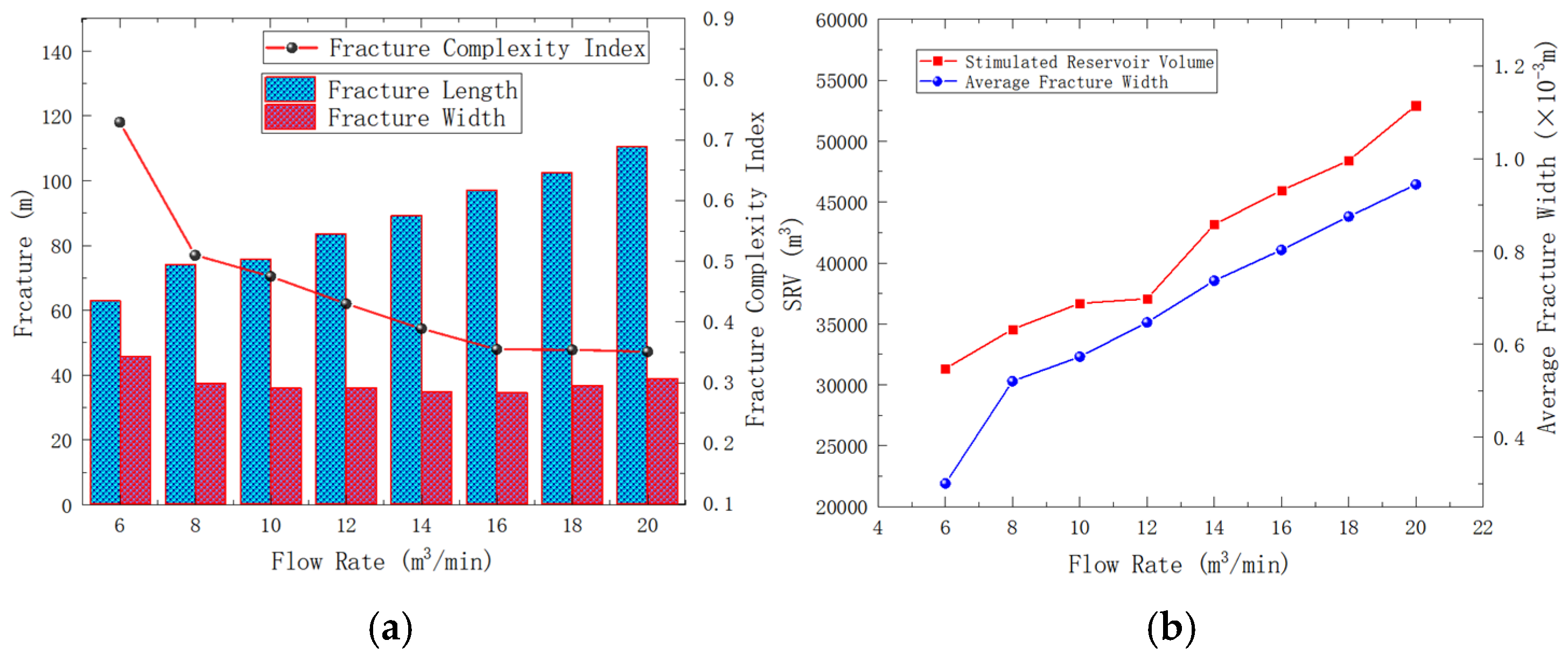
4.4. Effect of the Liquid Injection Rate in Coal Seams on Hydraulic Fracture Propagation

Based on the established hydraulic fracture propagation model, the hydraulic fracture propagation in the coal seam is simulated under an injection rate of 6 m3/min, 8 m3/min, 10 m3/min, 12 m3/min, 14 m3/min, 16 m3/min, 18 m3/min, and 20 m3/min. It can be seen from Figure 28 and Figure 29 that the fracture length and SRV increase continuously as the liquid injection rate increases. When the liquid injection rate increased to 18 m3/min, although the fracture length increased slowly, the fracture width (the maximum fracture aperture was set at 3 × 10⁻³ m) continued to increase. This means that a large injection rate can increase fracture width and facilitate subsequent proppant entry into the fracture.
The liquid injection rate increased from 6 m3/min to 20 m3/min, SRV increased from 3.13 × 10⁵ m3 to 5.3 × 10⁵ m3, an increase of 63.2%, and the fracture length increased from 69.2 m to 110.1 m, an increase of 59.1%, as shown in Figure 30a. The fracture width was calculated through the code, and the fracture width increased from 0.3 × 10⁻³ m to 0.94 × 10⁻³ m with the increase in liquid injection rate, an increase of 213%. Figure 30b shows the variation in average SRV and the fracture width averaged under different injection rates. With the increase in the liquid injection rate, the fracture length, SRV, and fracture width all showed a large trend. The coal reservoir is 20 m thick. As the displacement increases to 20 m3/min, the hydraulic fracture still does not penetrate the coal seam. It is suggested that we use a large injection rate for ultra-thick coal seams in hydraulic fracturing operations. Previously, scholars studied the effect of injection rate on hydraulic fracture propagation, mostly in terms of macroscopic fracture length and fracture width. In this paper, it was found that a large injection rate can increase the fracture width, and an increase in the fracture width facilitates the entry of a proppant. The study of fracture width has guiding significance for the laying of a proppant.

5. Conclusions

Based on the established block discrete element three-dimensional complex fracture propagation model, the effects of cleat fracture continuity, spacing of cleats system, angle between face cleats and butt cleats, geostress difference at different cleat angles, and different fluid injection displacements on hydraulic fracture propagation in thicker coal reservoirs are investigated. It is also found in the study that the propagation of hydraulic fractures in the coal seam with fracture development is influenced by the direction of the fracture and ground stress. A research method is provided to describe the fracture width and the steering angle of cleats-induced fractures to evaluate the influence of cleats on the direction of hydraulic fracture propagation. From the analyzed results, the following conclusions are drawn:
(1)
When the injection hole is on the cleats, the hydraulic fracture preferentially extends along the cleats system, and the hydraulic fracture shows a “cross” propagation. The coal cleats have an inducing effect on the direction of hydraulic fracture propagation; the coal cleats have a small effect on SRV but have a large effect on the fracture width. The coal reservoir hardly gains a large reforming volume away from the injection hole; the angle of the cleat is from 0° to 45°, and the steering angle of cleats-induced fractures increases to 17.1°, and the cleat angle is from 0° to 45°, and the steering angle of cleats-induced fracture increases to 17.1°. The cleat angle has a great influence on the hydraulic fracture propagation direction, and when the cleat angle is from 45° to 90°, the coal cleat gradually loses its inducing effect on the hydraulic fracture propagation direction.
(2)
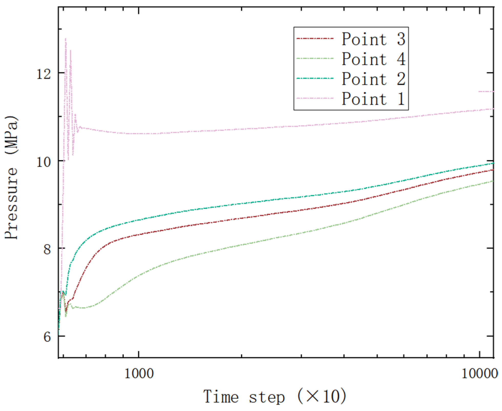
High viscosity liquid will limit the fracture length but will increase the fracture width; it also increases the extension pressure of the fracture. Under the influence of cleats, the pore pressure is unstable at the initial water injection hole.
(3)
The influence of maximum principal stress on the propagation direction of hydraulic fractures is greater than that of the direction of cleats. With the increase of the geostress difference, the fracture length gradually becomes smaller, the fracture width gradually becomes larger, and the Ifc decreases. The smaller the angle between the direction of the face cleat and the direction of maximum principal stress is, the larger the fracture length is and the smaller the fracture width is.
(4)
In coal seam fracturing operations where the seam thickness exceeds 20 m, due to the significantly greater fracture strength of the caprock compared to the coal seam rock, it is nearly impossible for hydraulic fractures to penetrate the caprock. Higher pumping rates can also result in increased fracture width, which benefits the entry of proppants.

Author Contributions

Conceptualization: H.X. and H.Z. Methodology: H.Z. Validation: H.W. and X.X. Investigation: H.X. and H.Z. Data curation: C.W. Writing—original Draft preparation: H.Z. Writing—review and editing: H.X. and H.Z. Visualization: H.W. Supervision: H.X. Project administration: H.Z. Funding acquisition: H.X. Resources: H.X. and J.L. All authors have read and agreed to the published version of the manuscript.

Funding

The authors sincerely thank the National Natural Science Foundation of China (NSFC) (52274033) and the Scientific and Technological Research Program of Chongqing Municipal Education Commission (GN:KJQN202201521) for their financial support.

Data Availability Statement

The data that support the findings of this study are available from the corresponding author upon reasonable request.

Conflicts of Interest

Author Junchen Liu was employed by the company PetroChina Southwest Oil and Gas Field Company. The remaining authors declare that the research was conducted in the absence of any commercial or financial relationships that could be construed as a potential conflict of interest. The PetroChina Southwest Oil and Gas Field Company had no role in the design of the study; in the collection, analyses, or interpretation of data; in the writing of the manuscript, or in the decision to publish the results.

References

  1. Mohamed, T.; Mehana, M. Coalbed methane characterization and modeling: Review and outlook. Energy Sources Part A Recovery Util. Environ. Eff. 2020, 47, 2874–2896. [Google Scholar] [CrossRef]
  2. Ting, F.T.C. Origin and Spacing of Cleats in Coal Beds. ASME J. Press. Vessel Technol. 1977, 99, 624–626. [Google Scholar] [CrossRef]
  3. Zhang, J. Numerical simulation of hydraulic fracturing coalbed methane reservoir. Fuel 2014, 136, 57–61. [Google Scholar] [CrossRef]
  4. Huang, T.; Wang, Z. A novel numerical reconstruction method of coal based on characteristics of the cleat system. Fuel 2024, 372, 132213. [Google Scholar] [CrossRef]
  5. Mostaghimi, P.; Armstrong, R.T.; Gerami, A.; Hu, Y.; Jing, Y.; Kamali, F.; Liu, M.; Liu, Z.; Lu, X.; Ramandi, H.L.; et al. Cleat-scale characterisation of coal: An overview. J. Nat. Gas Sci. Eng. 2017, 39, 143–160. [Google Scholar] [CrossRef]
  6. Cheng, X.; Luan, H.; Chen, L.; Jiang, Y.; Han, W. Numerical investigation on mechanical properties of inhomogeneous coal under uniaxial compression and the role of cleat distribution. Bull. Eng. Geol. Environ. 2021, 80, 7009–7027. [Google Scholar] [CrossRef]
  7. Fan, T.; Zhang, G.; Cui, J. The impact of cleats on hydraulic fracture initiation and propagation in coal seams. Pet. Sci. 2014, 11, 532–539. [Google Scholar]
  8. Li, Q.; Li, Y.; Cheng, Y.; Li, Q.; Wang, F.; Wei, J.; Liu, Y.; Zhang, C.; Song, B.; Yan, C.; et al. Numerical simulation of fracture reorientation during hydraulic fracturing in perforated horizontal well in shale reservoirs. Energy Sources Part A Recovery Util. Environ. Eff. 2018, 40, 1807–1813. [Google Scholar] [CrossRef]
  9. Li, Q.; Li, Q.; Cao, H.; Wu, J.; Wang, F.; Wang, Y. The Crack Propagation Behaviour of CO2 Fracturing Fluid in Unconventional Low Permeability Reservoirs: Factor Analysis and Mechanism Revelation. Processes 2025, 13, 159. [Google Scholar] [CrossRef]
  10. Tan, P.; Fu, S.; Huang, L.; Chen, Z.; Cao, J. Effects of orthogonal cleat structures on hydraulic fracture evolution behavior. Geoenergy Sci. Eng. 2024, 241, 213119. [Google Scholar]
  11. Yang, T.H.; Jia, P.; Shi, W.H.; Wang, P.T.; Liu, H.L.; Yu, Q.L. Seepage-stress coupled analysis on anisotropic characteristics of the fractured rock mass around roadway. Tunn. Undergr. Space Technol. 2014, 43, 11–19. [Google Scholar] [CrossRef]
  12. Wenli, Y.; Sharifzadeh, M.; Yang, Z.; Xu, G.; Fang, Z. Assessment of fracture characteristics controlling fluid flow performance in discrete fracture networks (DFN). J. Pet. Sci. Eng. 2019, 178, 1104–1111. [Google Scholar] [CrossRef]
  13. Jing, Y.; Armstrong, R.T.; Ramandi, H.; Mostaghimi, P. Coal cleat reconstruction using micro-computed tomography imaging. Fuel 2016, 181, 286–299. [Google Scholar] [CrossRef]
  14. Hui, G.; Chun, F.; Zhu, X. Three-dimensional hydraulic fracturing analysis of coal bed methane based on continuous-discontinuous element method. J. Shandong Univ. (Eng. Sci.) 2021, 51, 119–128. [Google Scholar]
  15. Tao, X.; Su, G.; Chi, B.; Sun, P. Feasibility Study of Separate Layer Fracturing and Multi-layer Drainage for CBM in Sange Area, Eastern Margin of Ordos Basin. Coal Geol. China 2013, 25, 52–54. [Google Scholar]
  16. Zou, J.; Chen, W.; Yuan, J.; Yang, D.; Yang, J. 3-D numerical simulation of hydraulic fracturing in a CBM reservoir. J. Nat. Gas Sci. Eng. 2017, 37, 386–396. [Google Scholar] [CrossRef]
  17. Huang, S.; Lu, Y.; Ge, Z.; Zhou, Z.; Guan, Y.; Chen, X. Fracture Mechanism of Coal Seams Induced by a Multibranched Borehole Drilling (MBBD) Technique to Enhance Coalbed Methane (CBM) Extraction. Energy Fuels 2023, 37, 13034–13047. [Google Scholar]
  18. Zheng, Y.; He, R.; Huang, L.; Bai, Y.; Wang, C.; Chen, W.; Wang, W. Exploring the effect of engineering parameters on the penetration of hydraulic fractures through bedding planes in different propagation regimes. Comput. Geotech. 2022, 146, 104736. [Google Scholar]
  19. Itasca Consulting Group, Inc. 3DEC, Version 5.2; Itasca Consulting Group, Inc.: Minneapolis, MN, USA, 2016. Available online: https://www.itascacg.com/software/3dec (accessed on 16 February 2025).
  20. Xiong, D.; He, J.; Ma, X.; Qu, Z.; Guo, T.; Ma, S. Breakthrough, future challenges and countermeasures of deep coalbed methane in the eastern margin of Ordos Basin: A case study of Linxing-Shenfu block. J. China Coal Soc. 2023, 49, 1827. [Google Scholar] [CrossRef]
  21. Laubach, S.; Marrett, R.; Olson, J.; Scott, A. Characteristics and origins of coal cleat: A review. Int. J. Coal Geol. 1998, 35, 175–207. [Google Scholar]
  22. Karimpouli, S.; Tahmasebi, P.; Ramandi, H.L. A review of experimental and numerical modeling of digital coalbed methane: Imaging, segmentation, fracture modeling and permeability prediction. Int. J. Coal Geol. 2020, 228, 103552. [Google Scholar] [CrossRef]
  23. Ramandi, H.L.; Mostaghimi, P.; Armstrong, R.T.R.T. Digital rock analysis for accurate prediction of fractured media permeability. J. Hydrol. 2017, 554, 817–826. [Google Scholar] [CrossRef]
  24. Zheng, X. Study on Hydraulic Fracture Propagation Law of Coal Considering Soft Interlaye and Coal Fracture Conductivity. Master’s Thesis, Chongqing University, Chongqing, China, 2021. [Google Scholar] [CrossRef]
  25. Cipolla, C.L.; Warpinski, N.R.; Mayerhofer, M.J.; Lolon, E.P.; Vincent, M.C. The relationship between fracture complexity, reservoir properties, and fracture treatment design. In Proceedings of the SPE Annual Technical Conference and Exhibition, Denver, CO, USA, 21–24 September 2008. SPE-115769-MS. [Google Scholar]
  26. Hubbert, M.K.; Willis, D.G. Mechanics of hydraulic fracturing. Trans. AIME 1957, 210, 153–168. [Google Scholar] [CrossRef]
Figure 1. Schematic diagram of the block discrete element method.
Processes 13 01036 g001
Figure 2. Schematic of the 3D coalbed methane hydraulic fracture propagation model.
Processes 13 01036 g002
Figure 3. (a): Schematic diagram of the rock block of the 9# coal seam of the Longtan Formation, Guizhou Province, China, (b): schematic diagram of the cleats of the cross-section of the core of the 8# coal seam of the Longtan Formation, Guizhou Province, China, and (c): schematic diagram of the longitudinal cross-section of the core of the 8# coal seam of the Longtan Formation, Guizhou Province, China.
Processes 13 01036 g003
Figure 4. (a) Schematic cross-section of coal block, (b) diagram of coal cleats modeling.
Processes 13 01036 g004
Figure 5. Geometrical modeling of cleats in coal seams.
Processes 13 01036 g005
Figure 6. Simulated model diagrams under different cleat distribution characteristics.
Processes 13 01036 g006
Figure 7. Schematic diagram of the location of water injection holes in different lithologies.
Processes 13 01036 g007
Figure 8. Variation in pore fluid pressure in different lithologies.
Processes 13 01036 g008
Figure 9. Diagrams of fracture morphology in x-axis and y-axis profiles under different cleat continuity conditions.
Processes 13 01036 g009
Figure 10. Schematic diagram of a hydraulic fracture captured by the cleat system.
Processes 13 01036 g010
Figure 11. Quantification of fracture width with different cleat continuity.
Processes 13 01036 g011
Figure 12. Schematic diagram of SRV equivalent calculation.
Processes 13 01036 g012
Figure 13. Morphology of fracture with different cleat system spacing.
Processes 13 01036 g013
Figure 14. Fracture morphology of the x-axis and y-axis profiles with different cleat system spacing.
Processes 13 01036 g014
Figure 15. Variation in fracture width under different cleat system spacing.
Processes 13 01036 g015
Figure 16. Hydraulic fracture parameter data chart: (a) fracture length, width and Ifc data at different spacing, and (b) average values of fracture width and SRV at different spacing.
Processes 13 01036 g016
Figure 17. Fracture morphology of X-axis and Y-axis profiles at different cleat angles.
Processes 13 01036 g017
Figure 18. Schematic diagram of fracture diversion induced by cleats: (a) the cleats in coal align with the direction of the maximum principal stress and (b) the cleats in coal are oriented at an angle to the direction of the maximum principal stress.
Processes 13 01036 g018
Figure 19. Schematic diagram of the steering angle induced by cleats.
Processes 13 01036 g019
Figure 20. Fracture morphology maps in 3D at different cleat angles.
Processes 13 01036 g020
Figure 21. Hydraulic fracture parameter diagrams under varying intersection angles between face cleats and butt cleats: (a) fracture length, width, and Ifc data graph at different spacing and (b) average values of fracture width and SRV at different spacing.
Processes 13 01036 g021
Figure 22. Schematic diagram of pressure monitoring points.
Processes 13 01036 g022
Figure 23. Diagram of pressure change at different points.
Processes 13 01036 g023
Figure 24. Diagram of fracture morphology at different viscosities.
Processes 13 01036 g024
Figure 25. Diagram of pressure data at different viscosities.
Processes 13 01036 g025
Figure 26. Fracture morphology under different coal cleat angles and differential geostress.
Processes 13 01036 g026aProcesses 13 01036 g026b
Figure 27. Hydraulic fracture parameter data chart: (a) data diagram of steering angle of cleat-induced fracture under the influence of cleat angle and geostress difference, (b) data diagram of depicting changes in fracture length, width, and Ifc at the cleat angle of 15° under geostress difference, and (c) data diagram of depicting changes in fracture length, width, and Ifc at the cleat angle of 30° under geostress difference.
Processes 13 01036 g027
Figure 28. Fracture morphology at different fluid injection displacements.
Processes 13 01036 g028
Figure 29. Fracture morphology of X- and Z-axis profiles with different fluid injection displacements.
Processes 13 01036 g029
Figure 30. Hydraulic fracture parameter diagrams under varying injection rates: (a) fracture length, width, and Ifc data graph at different spacings and (b) average values of fracture width and SRV at different spacings.
Processes 13 01036 g030
Table 1. Rock mechanical parameters.
Coal SeamRoof and Floor
Input parametersValuesInput parametersValues
Modulus of elasticity E (GPa)10Modulus of elasticity E (GPa)25
Poisson’s ratio μ (%)0.25Poisson’s ratio μ (%)0.2
Rock density (kg/m3)1200Rock density (kg/m3)2590
Rock tensile strength (MPa)1.5Rock tensile strength (MPa)5
Block normal stiffness kn (GPa)1Block normal stiffness (GPa)5
Block shear stiffness ks (GPa)1Block shear stiffness (GPa)5
Table 2. Fluid parameter table.
Input ParametersValues
Fluid bulk modulus K (GPa)3
Fluid density (kg/m3)1000
Fluid viscosity η (Pa·s)0.0015
Table 3. Initial conditions of the model.
Input ParametersValues
Stress gradient (MPa/km)25
Depth of center of mass (m)600
Horizontal minimum principal stress (MPa)12
Horizontal maximum principal stress (MPa)15
Table 4. Statistical table of mechanical characteristics of coal roof and bottom plate of 16# coal guide shaft H.
BlockRock TypeCompressive Strength
(MPa)
Young’s Modulus (GPa)Poisson’s RatioFracture Pressure (MPa)Horizontal Minimum Principal Stress (MPa)Horizontal Maximum Principal Stress (MPa)Vertical Principal Stress (MPa)
Daijiatian No. 16 Coal SeamRoof
(siltstone)
25.13.20.1915.815.116.516.9
Coal6.60.90.2111.511.614.217
Floor (muddy siltstone)17.82.70.1715.214.716.117.1
Disclaimer/Publisher’s Note: The statements, opinions and data contained in all publications are solely those of the individual author(s) and contributor(s) and not of MDPI and/or the editor(s). MDPI and/or the editor(s) disclaim responsibility for any injury to people or property resulting from any ideas, methods, instructions or products referred to in the content.

