Article

Physical Simulation Tests on Deformation and Instability of Composite Roof in Large-Section Coal Roadway Under Different Burial Depths

1
Key Laboratory of Xinjiang Coal Resources Green Mining (Xinjiang Institute of Engineering), Ministry of Education, Urumqi 830023, China
2
Yushuling Coal Mine Co., Ltd., Xinjiang Yuneng Investment Group Co., Ltd., Kuche 842000, China
3
School of Civil and Transportation Engineering, Ningbo University of Technology, Ningbo 315211, China
*
Author to whom correspondence should be addressed.
Processes 2025, 13(4), 1003; https://doi.org/10.3390/pr13041003
Submission received: 17 December 2024 / Revised: 25 February 2025 / Accepted: 11 March 2025 / Published: 27 March 2025
(This article belongs to the Section Energy Systems)

Abstract

:
In response to the difficulty of controlling the layered composite roof of large-section coal roadways and the problem of slow excavation speed caused by unreasonable support parameter values, a dynamic staged control principle for surrounding rock based on “high-strength passive temporary support near the excavation face, combined with active support of rear bolts and anchor cables” is proposed by analyzing the evolution law of rock release stress under the spatial effect of excavation face. Based on the geological conditions of the 1211 (1) transportation roadway in Guqiao Coal Mine, a similar physical simulation test model was constructed to conduct experimental research on the bearing capacity and deformation instability mechanism of the surrounding rock of the layered-composite-roof coal roadway. The law of influence of staged support on the deformation and failure evolution of the surrounding rock was obtained. The research results show the following: (1) After loading above the model, the vertical stress on the roof increases rapidly in a “stepped” manner. After unloading the roadway excavation, due to the release of constraints on the roof above the roadway, the vertical stress on the roof rapidly decreases, especially in the temporary support area where the reduction in vertical stress on the roof is most significant. (2) As the vertical load increases, the displacement curve of the roof gradually evolves into a “V” shape. The farther away from the center of the roadway, the smaller the subsidence of the roof. When loaded to 54.45 kN, the subsidence of the roof increases, indicating that the development of roof delamination cracks is faster, and delamination occurs between 12 cm and 22 cm above the roof. (3) With the continuous increase of axial load, cracks first appear around the roof and slightly sink. Then, the cracks gradually expand and penetrate, causing instability and failure of the roadway roof. When the mining stress reaches 54.45 kN, the middle part of the roadway roof in the axial direction breaks, and the cracks penetrate, resulting in overall collapse.

1. Introduction

The main method of coal resource extraction is underground mining, but excavation and back-mining are the two key links in the current mining technology system [1,2]. With the high production of coal leading to huge consumption of coal mine roadways, in order to solve the problem of slow excavation speed, it is usually necessary to increase the number of excavation working faces to achieve normal mining replacement. However, this has also caused an unfavorable situation where the excavation ratio is maintained at around 1:3 for considerable time, making it difficult for the excavation speed to keep up with the mining speed. As a result, there are many problems such as increased difficulty in excavation construction and intensified safety accidents, which seriously affect normal underground production. The problem of mining imbalance has become a bottleneck restricting high production and efficiency in mines [3,4,5,6]. As coal roadways present the largest amount of excavation work in coal mines, their excavation speed has always remained at a relatively low level [7,8]. Therefore, rapid excavation of coal roadways is one of the key issues that urgently need to be addressed in current coal mine production.
Rapid excavation of coal roadways is a complex alternating construction process, and each link will affect the speed of roadway excavation. The processes that have the greatest impact on excavation speed are mainly excavation and support [9,10]. The essence of rapid excavation is to use excavation and supporting equipment that is suitable for the engineering geological conditions to form an excavation operation line, maximizing the excavation speed. Due to the more complex stress state of the surrounding rock in the actual site, especially when encountering geological conditions such as soft and broken surrounding rock, composite roof, etc., the roof must strictly follow the “one excavation, one support” excavation method, and it is difficult to achieve completely parallel excavation and support operations [11,12,13]. If the excavation working face adopts scientific and reasonable temporary support, it can not only ensure the safety of excavation construction, but also extend the temporary support range of the excavation face to the rear of the tunneling machine, providing an important way to achieve safe and efficient excavation of large-section composite-roof coal roadways.
At present, a large number of researchers at home and abroad have conducted extensive research on the mechanism of deformation and instability of the roof during rapid excavation of coal roadways. Among them, Chu et al. [14] established a beam structure mechanics model to analyze the subsidence law of the roof in the empty roof area, and determined the stability factors and reasonable empty roof distance of the heading roof during excavation. Zhou et al. [15] conducted a study on the disturbance effects of deep roadway excavation, and the results showed that there are spatiotemporal effects on the stress and deformation of the surrounding rock near the excavation face. Sofianos [16] analyzed the deformation law of the roof under different roof thickness conditions. As the roof thickness increases, the deformation of the roof decreases significantly. The results show that the sensitivity of roof deformation to roof thickness is high. Zhao [17] systematically studied the deformation and failure mechanism of the coal roadway composite roof based on the 53122 working face roadway of Zhaozhuang Mine, revealed the stability mechanism of the coal roadway composite roof and proposed safety control technology for it, and achieved good on-site application results. Yu et al. [18] and others studied the evolution law of stress, displacement, and plastic zone of roadway surrounding rock under the condition of a composite roof, revealed the deformation characteristics and instability mechanism of the composite roof, and proposed the stability control principle thereof. Guo [19] clarified the connotation of the circle layer linkage effect and the core of the roof support coordination technology in response to the problems of large deformation of surrounding rock and imbalance of excavation and support in deep-buried large-section coal tunnels. He proposed a thick-layer cross-border anchoring support technology with singularity, low density, and high efficiency.
The current research focuses on the mechanical analysis and numerical simulation of the deformation and instability mechanism of a coal roadway roof. Based on this, corresponding rock support schemes are formulated, and the on-site application effect is evaluated. However, there are few reports on physical simulation experiments that have advantages such as high simulation accuracy, good reducibility, easy operation, and intuitive presentation of rock deformation processes and results. In order to further study the bearing capacity and deformation instability mechanism of the coal roadway roof, this article proposes the dynamic staged control principle of surrounding rock by analyzing the spatial constraint effect of the roadway excavation face and proposing “high-strength passive temporary support near the excavation face, combined with active support of rear bolts and anchor cables”. Based on similar simulation experiments, we analyze the impact of increasing mining depth on the deformation and failure evolution of the roadway roof, in order to provide a basis for similar roadway excavation and support design.

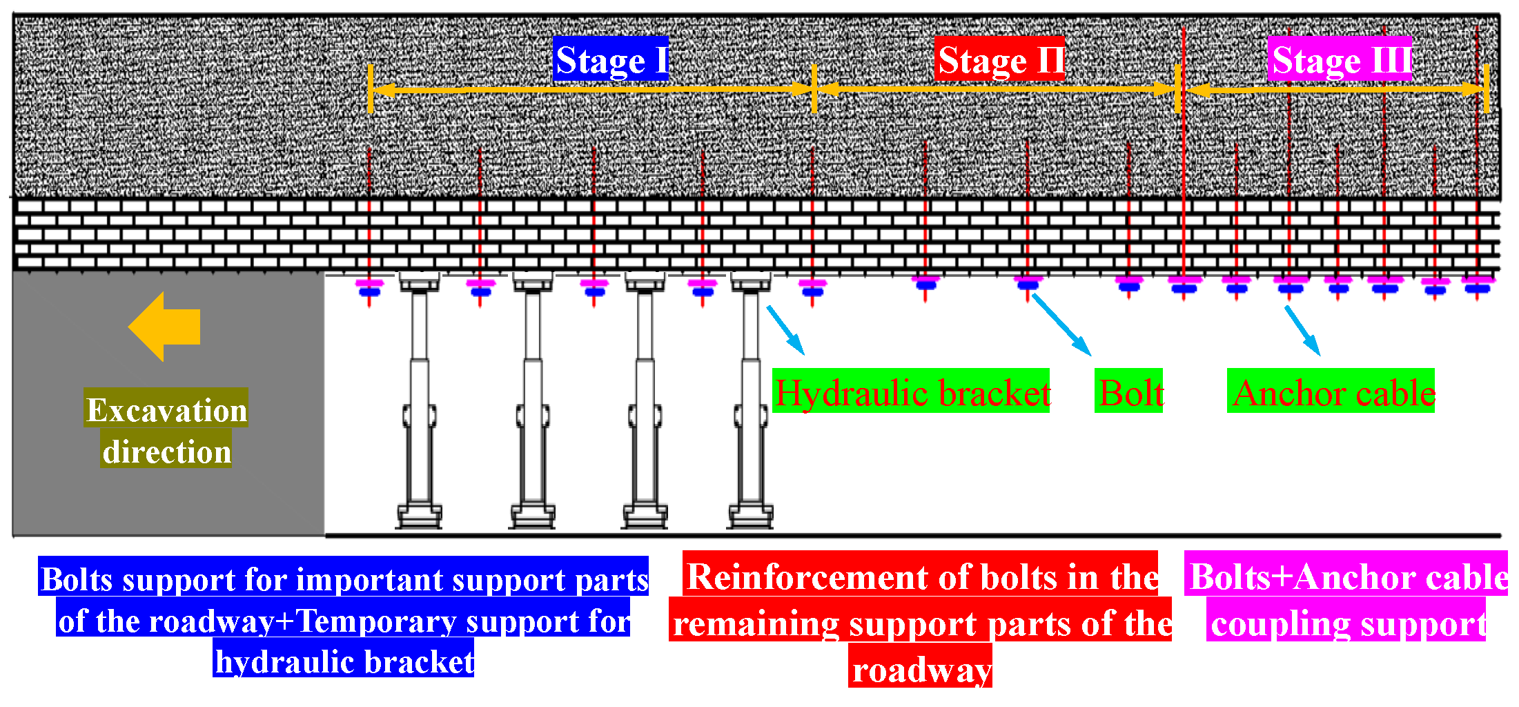
2. Principle of Staged Control of Coal Roadway Composite Roof

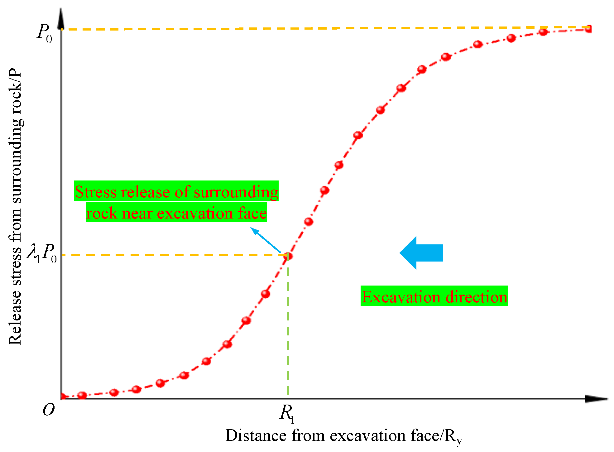
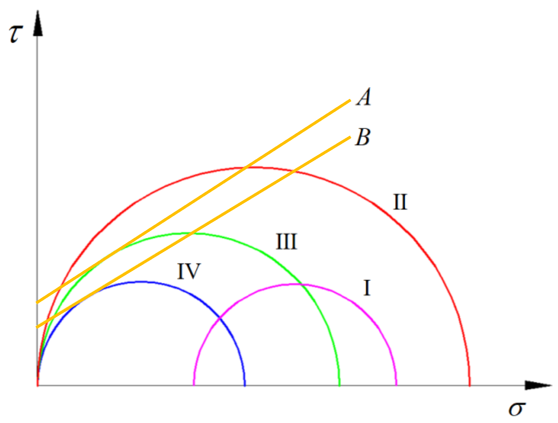
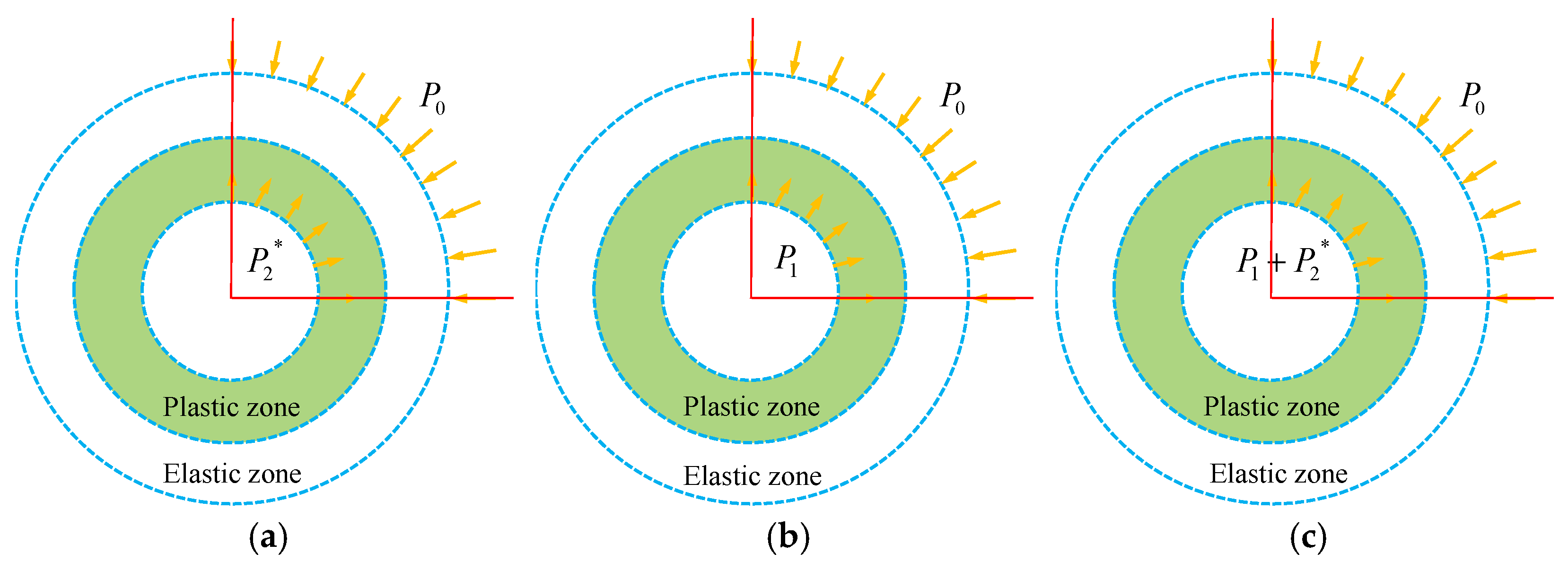
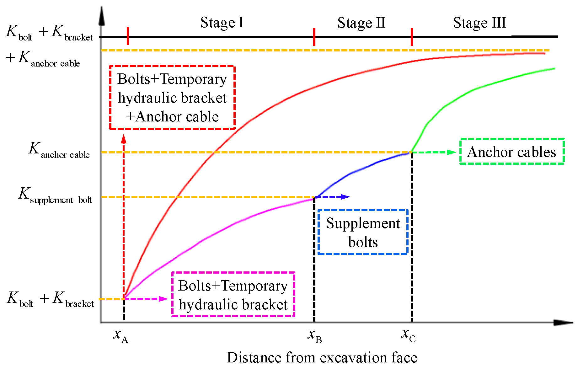
2.1. Characteristics of Spatiotemporal Effects on Excavation Face

The excavation of the roadway causes single-sided unloading of the surrounding rock, and the surrounding rock transitions from a three-dimensional stress equilibrium state to a two-dimensional stress state. The release of stress and deformation of the surrounding rock correspond to each other, that is, the greater the stress released by the surrounding rock, the greater the corresponding deformation. After applying the support structure, the stress state of the surrounding rock was greatly improved, driving the stress of the surrounding rock to transition from a two-dimensional stress state to a three-dimensional stress state, and improving the stability of the surrounding rock. During the process of tunnel excavation, the stress in the surrounding rock is gradually released with the cyclic advancement and time variation of the excavation working face. The released stress in the surrounding rock is [20]:
P t , y = μ 1 2 1 R 2 r 2 λ y p 0 E R E t
where μ is Poisson’s ratio, E is the elastic modulus, P0 is the initial stress, R is the equivalent circle radius of the roadway, E(t) is the equivalent modulus of surrounding rock, and λy is the stress release coefficient of the surrounding rock.
In the engineering example, it is assumed that the equivalent modulus of the surrounding rock is E(t) = E, and the three-dimensional space under spatiotemporal effects can be transformed into a two-dimensional space under spatial effects for analysis. Due to the spatial effect of the excavation face, the range of influence is from behind the excavation face 6R to the front of the excavation face 4R. When the influence range exceeds the end, the stress released by the surrounding rock reaches its maximum, which is the original rock stress. Therefore, according to Equation (1), the variation law of the released stress of the surrounding rock under the spatial effect of the excavation face is obtained, as shown in Figure 1.
Affected by the spatial effect of excavation face, the deformation and stress release of surrounding rock need to go through a process. Near the excavation face, the deformation and stress release of surrounding rock are relatively small. As the distance from the excavation face increases, the deformation and stress release of surrounding rock gradually increase. Obviously, it is unreasonable to use the maximum stress P0 for a single support design. With the cyclic advancement of the excavation face, the deformation of the surrounding rock shows a non-linear and non-increasing trend until the deformation of the surrounding rock is in a stable period. In Figure 2, I represents the stress circle before excavation, II represents the stress circle immediately after excavation, III represents the stress circle shortly after excavation, IV represents the stress circle after excavation for a long time, A represents the envelope line after excavation, and B represents the long-term envelope.
To quantitatively characterize the spatial constraint effect of the excavation face mentioned above, the concept of “virtual support force” is introduced [21]. At this time, the surrounding rock of the roadway is deformed under the combined actions of the original rock stress p0, virtual support force p2*, and support reaction force p1, as shown in Figure 3. On this basis, considering the theoretical formula for radial displacement of roadways, a functional relationship between the surrounding rock displacement, virtual support force, and support reaction force can be established.
After applying the support structure, the surrounding rock pressure is jointly borne by the support reaction force p1 and the virtual support force p2*, and the bolt and anchor cable meet the deformation coordination condition. Under any stress state, the radial displacement around the roadway is [22]:
u R 0 x = R 0 f p 1 x + p 2 * x
In Equation (2), p 1 ( x ) and p 2 * ( x ) are the support reaction force and virtual support force of the composite structure at a distance from the excavation face, respectively. By considering the relationship between support deformation, stiffness, and stress, the relationship between the distance increment and peripheral displacement increment of the roadway can be obtained, namely the dynamic interaction equation between roadway surrounding rock and support:
Δ u R 0 = R 0 f d p 1 x d x Δ x + d p 2 * x d x Δ x
Due to the unloading effect of roadway excavation, the stress release in the shallow range of the surrounding rock is relatively high, and the deformation of the surrounding rock increases accordingly. The development range of the plastic zone increases and gradually expands to the deep. Its strength and elastic modulus significantly decrease, and the stress state of the roof changes. Under the action of redistributed stress, the roof will undergo plastic deformation or loosening failure. Through the analysis of the stress generation mechanism during the formation process of the roadway, it is found that due to the more complex stress state of the surrounding rock in the actual site, especially when encountering geological conditions such as soft and broken surrounding rock and composite roof, if not supported in a timely manner, problems such as roof collapse are highly likely to occur. Moreover, the roof must strictly follow the “one excavation, one support” excavation process, and it is difficult to achieve completely parallel excavation and support operations, which seriously restricts the excavation speed of the coal roadway. To solve the problem of excessive support time during roadway excavation, based on the spatiotemporal effect of the excavation face and the bearing capacity of the surrounding rock itself, a dynamic staged control principle for the surrounding rock is proposed, which includes high-strength passive temporary roof protection near the excavation face and active support with rear bolts and anchor cables, as shown in Figure 3.
In Figure 4, line ab represents the one-time support method, and path acde represents the combined support method in stages. Among them, line ac is the first stage support, line cd is the second stage support, and line de is the third stage support. As the deformation of the surrounding rock develops and the stiffness of the support increases, the interaction between the surrounding rock and the support exhibits dynamic changes, as shown in Figure 5.

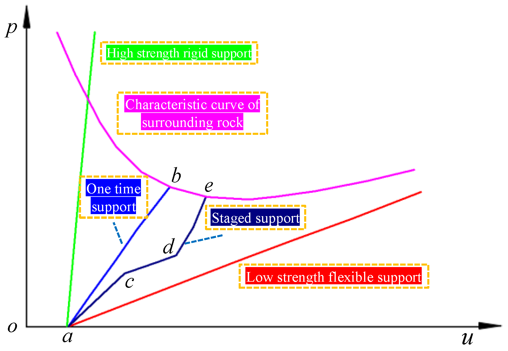
2.2. Stiffness Characteristics of Supporting Structures

According to Hoek and Oreste’s research [23,24], the maximum support stiffnesses provided by the support structure are given as follows:
The maximum support stiffness provided by the bolt is:
K bolt , max = π D bolt 2 E bolt S t S 1 4 L bolt + π D bolt 2 Q bolt E bolt
The maximum support stiffness provided by the anchor cable is:
K anchor   cable , max = π D anchor   cable 2 E anchor   cable S t S 1 4 L anchor   cable + π D anchor   cable 2 Q anchor   cable E anchor   cable
The maximum support stiffness provided by the bracket is:
K set = A set E set d R 0 h set / 2 2
In Equations (4)–(6), Qbolt and Qanchor cable are the load deformation constants of the anchorage end and anchorage head, respectively; Ebolt and Eanchor cable are the elastic modulus of the bolt and anchor cable, respectively; Dbolt and Danchor cable are the diameters of the bolt and anchor cable, respectively; Lbolt and Lanchor cable are the length of the bolt and anchor cable, respectively; St and S1 represent the radial and axial spacings between the bolt and anchor cable, respectively; Aset is the cross-sectional area of the bracket; Eset is the elastic modulus of the bracket; d is the axial spacing of the bracket; and hset is the vertical height of the cross-section of the bracket.
Assuming that the coal mine roadway maintains a constant excavation speed and continues to advance in a cyclic manner, the relationship between the bolts, anchor cables, and bracket on a certain section and the distance from the excavation face can be established as follows:
K x = K max 1 e α x x i / v
In Equation (7), α is the time constant for bolts, anchor cables, and support brackets; xi is the distance between the construction section and the excavation surface; and v is the excavation speed of the coal roadway.
When using support structures such as bolts, anchor cables, and temporary hydraulic brackets to bear the deformation pressure of surrounding rock in the different support stages mentioned above, the joint support structure can be regarded as a support system composed of various support units, that is, the total stiffness of the support system is approximately equal to the sum of the stiffnesses of individual support units. According to Equation (7), the relationship curve between the total stiffness of the support structure and the distance from the excavation face can be obtained as shown in Figure 6. Among the variables, xA, xB, and xC are the construction positions for applying corresponding support structures in the stage I, stage II, and stage III, respectively. When the roadway roof condition is relatively broken, hydraulic support can be used for temporary support in the period after the completion of a cycle of excavation footage, and roof bolts and upper bolts of the coal slope can be fully drilled. At this time, xA and xB are approximately equal. As the driving face continues to advance in cycles, it will eventually approach the maximum stiffness that can be provided by the combined support system.

3. Physical Similarity Simulation Test Scheme

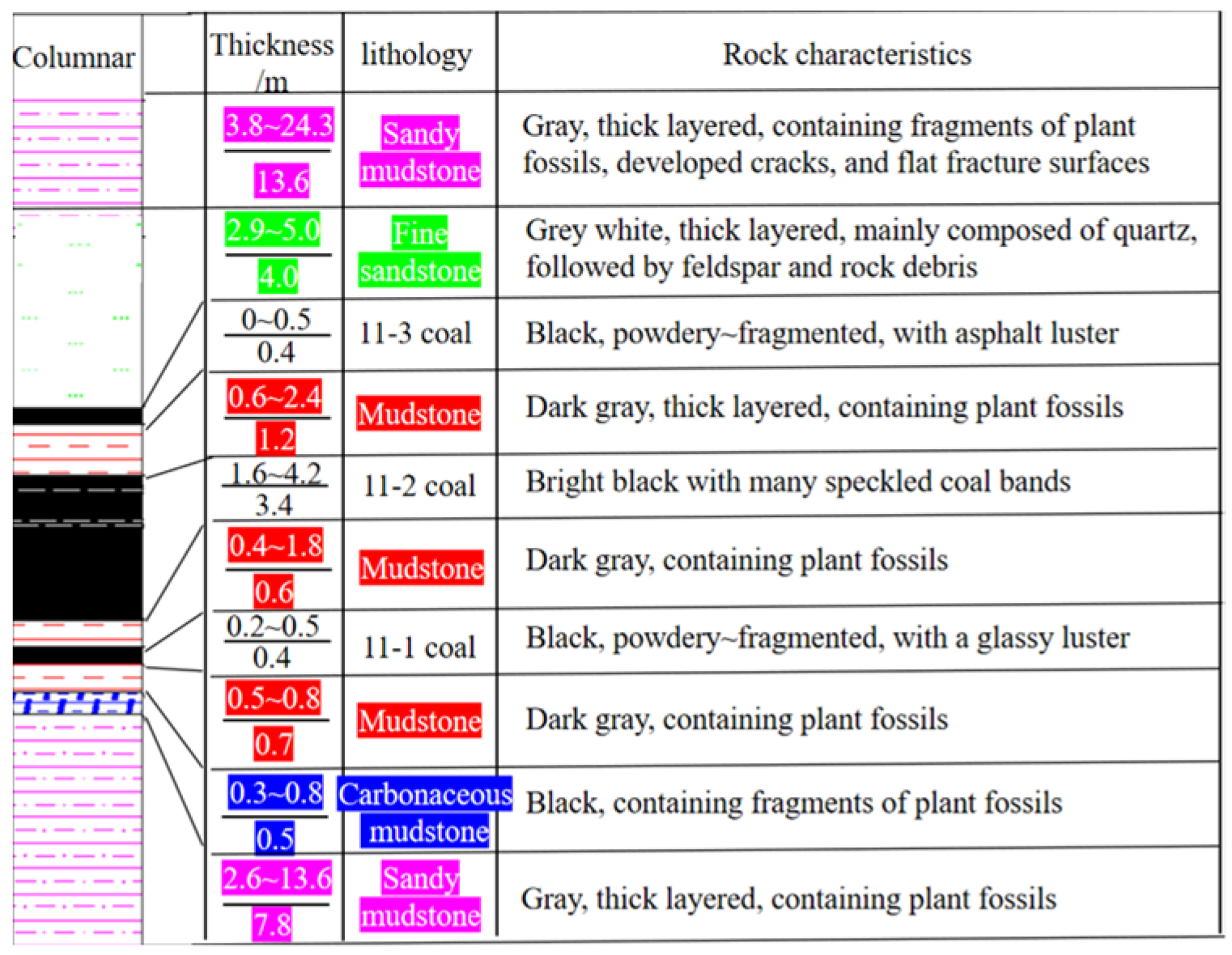
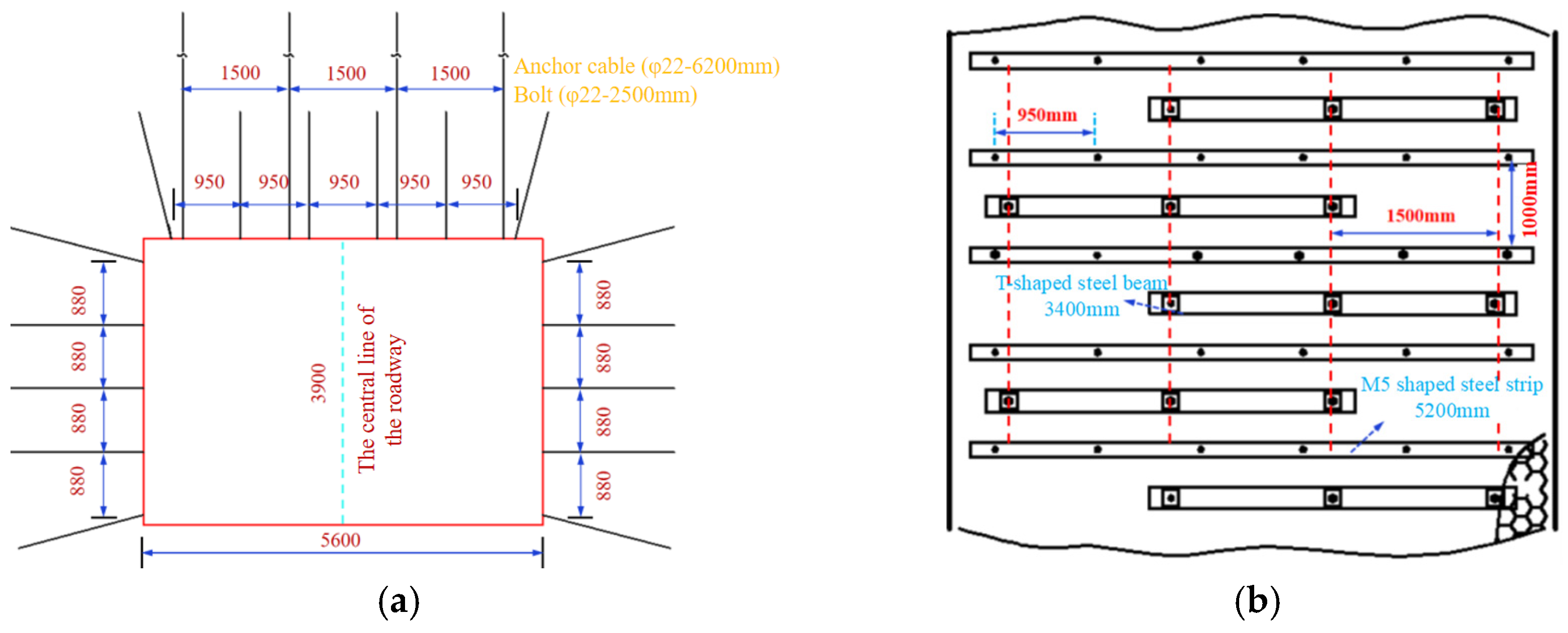
3.1. Overview of Prototype Engineering

The 1211 (1) working face of Guqiao Mine is mining coal seam 11-2, with a burial depth of about 610 m, a thickness of 3.4 m, and a dip angle of 6°, making it a nearly horizontal mining coal seam. The 11-2 coal seam has stable occurrence, mainly bright black, bright coal and dull coal, with many vitrified coal bands, brittle and glassy luster, belonging to the semi-bright coal type, locally intercalated with one to two layers of carbonaceous mudstone, with a thickness of 0.1–0.4 m. The coal seam structure is complex, and the dip angle of the coal seam varies greatly due to the influence of faults and other structures. The basic roof is composed of fine sandstone with a thickness of 2.9–5.0 m, which is thick-layered, mainly composed of quartz, followed by feldspar and rock debris, interbedded with thin layers of siltstone, showing deformation bedding. The immediate roof is composed of mudstone and an 11-3 coal seam, with a thickness of 0.6–2.9 m. The mudstone is thick-layered, with plant root fossils found in the upper part and plant stem and leaf fossils in the lower part. The 11-3 coal seam is powdery to fragmented, mainly consisting of bright coal, followed by dull coal, both of which are semi-bright coal with asphalt to glass luster. The immediate floor is composed of mudstone and an 11-1 coal seam, with a thickness of 1.4–3.9 m, and the lower part contains a thin layer of carbonaceous mudstone with a thickness of 0.3–0.8 m. The basic floor is sandy mudstone, with a thickness of 2.6–13.6 m, thick-layered, and containing copious plant fossils. A comprehensive bar chart of the 11-2 coal seam roof and floor is shown in Figure 7.
The design cross-section of the roadway is rectangular, with a cross-sectional size of 5.6 m × 3.9 m. The bolt mainly adopts a threaded steel pretension bolt, with a specification of Φ22 mm × 2500 mm. Six bolts are arranged on the roof with a spacing of 950 mm × 1000 mm, and five bolts are arranged on each rib with a spacing of 880 mm × 1000 mm. The anchor cable is arranged in an alternating manner of “3–3”, and its material is prestressed steel strand. The anchor cable specification is Φ22 mm × 6200 mm, and the spacing between anchor cables is 1500 mm × 1000 mm. The roadway support section is arranged as shown in Figure 8.

3.2. Design of Similar Simulation Test Scheme

To better simulate the similarity of the above-mentioned engineering sites, according to the similarity theory, it is necessary to comply with geometric similarity, material bulk density similarity, strength similarity, stress boundary condition similarity, and motion similarity. Based on this similarity theory, the corresponding similarity constants are obtained. Among them, in the following categories, the subscript P represents the prototype and M represents the model.
Geometric similarity ratio:
α L = L P L M
Bulk density similarity ratio:
α γ = γ P γ M
Stress similarity ratio:
α σ = σ P σ M = α L α γ
Excavation time ratio:
α T = T P T M = α L
In terms of selecting model materials, it is very difficult to obtain completely similar models due to conditional limitations. Similar simulation tests mainly focus on the deformation and failure characteristics of rock masses, and require high rock strength. Therefore, when selecting model materials, only strength (compressive or tensile strength of rocks) is used as a similarity criterion.
(1)
Determination of similar parameters
(a)
Geometric similarity ratio
A three-dimensional similarity simulation test platform with a size of 1100 mm × 1000 mm × 1000 mm is adopted. According to the excavation of the roadway, the impact range on the surrounding rock mass is generally 3–5 times the radius of the roadway, and the reserved boundary around the model is 100 mm. Therefore, according to Equation (8), the geometric similarity ratio of the model can be determined as 32, and the cross-sectional size of the model roadway can be determined as 175 mm × 125 mm. To facilitate the simulation of later roadway excavation, long wooden strips with similar cross-sectional shapes are used to simulate similar experimental roadway.
(b)
Stress similarity ratio
Due to limitations in experimental conditions, it is not possible to simulate the overlying rock layers from the upper boundary of the model to the surface. Therefore, it is necessary to determine the load applied to the upper boundary of the roadway model through the stress similarity ratio. According to the engineering geological conditions, the distance from the upper boundary of the model to the surface is 610 m, and the corresponding load is 15.25 MPa. For the convenience of simulation, the bulk density similarity ratio of the model is selected as 1.6, and the stress similarity ratio is 46. Therefore, the load applied to the upper boundary of the model is 0.33 MPa.
(c)
The ratio of excavation time between prototype and model
According to Equation (11), the excavation time ratio can be determined to be 5.38, which facilitates time simulation. Taking αT = 6, 4 h in a similar simulation test is equivalent to 1 day in the actual site.
(d)
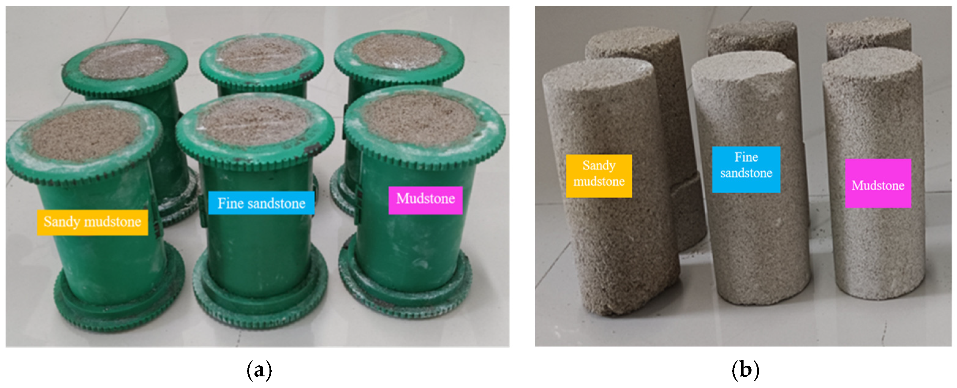
Similar model test materials
When selecting materials for similar model experiments, consideration should be given to the convenience of preparation, low cost, abundant materials, and the ability to achieve different mechanical properties of similar materials by changing the material ratio. Five types of coal rock formations with different ratios were selected, namely carbonaceous mudstone (ratio number: 1237), mudstone (ratio number: 864), coal (ratio number: 1055), sandy mudstone (ratio number: 773), and fine sandstone (ratio number: 655).
For this purpose, river sand, lime, and gypsum were selected as aggregates. In order to further simulate the lithological effect of actual rock layers, the above aggregates were mixed with water in different ratios and loaded into cylindrical molds with a size of φ 50 mm × 100 mm. The top of the mold was pressurized to the required size for the test, and the corresponding cylindrical specimens were made. The production and process of the specimens are shown in Figure 9.
After the production of the specimen, it was left at room temperature for about 30 min. The specimen was pressurized by an air pump at the bottom of the mold and removed from the mold. It was then placed in a curing box for 5 days. A uniaxial compression test was conducted using the RMT rock mechanics testing system to obtain physical and mechanical properties of similar physical simulation proportioned specimens, as shown in Table 1.
When laying rock layers, mica sheets are used for layering, and the mechanical parameters of each rock layer can be determined based on the stress similarity ratio, such as the uniaxial compressive strength and density of the rock layer. The mechanical parameters, ratios, and quantities of each rock layer in the similarity model are shown in Table 2.
(e)
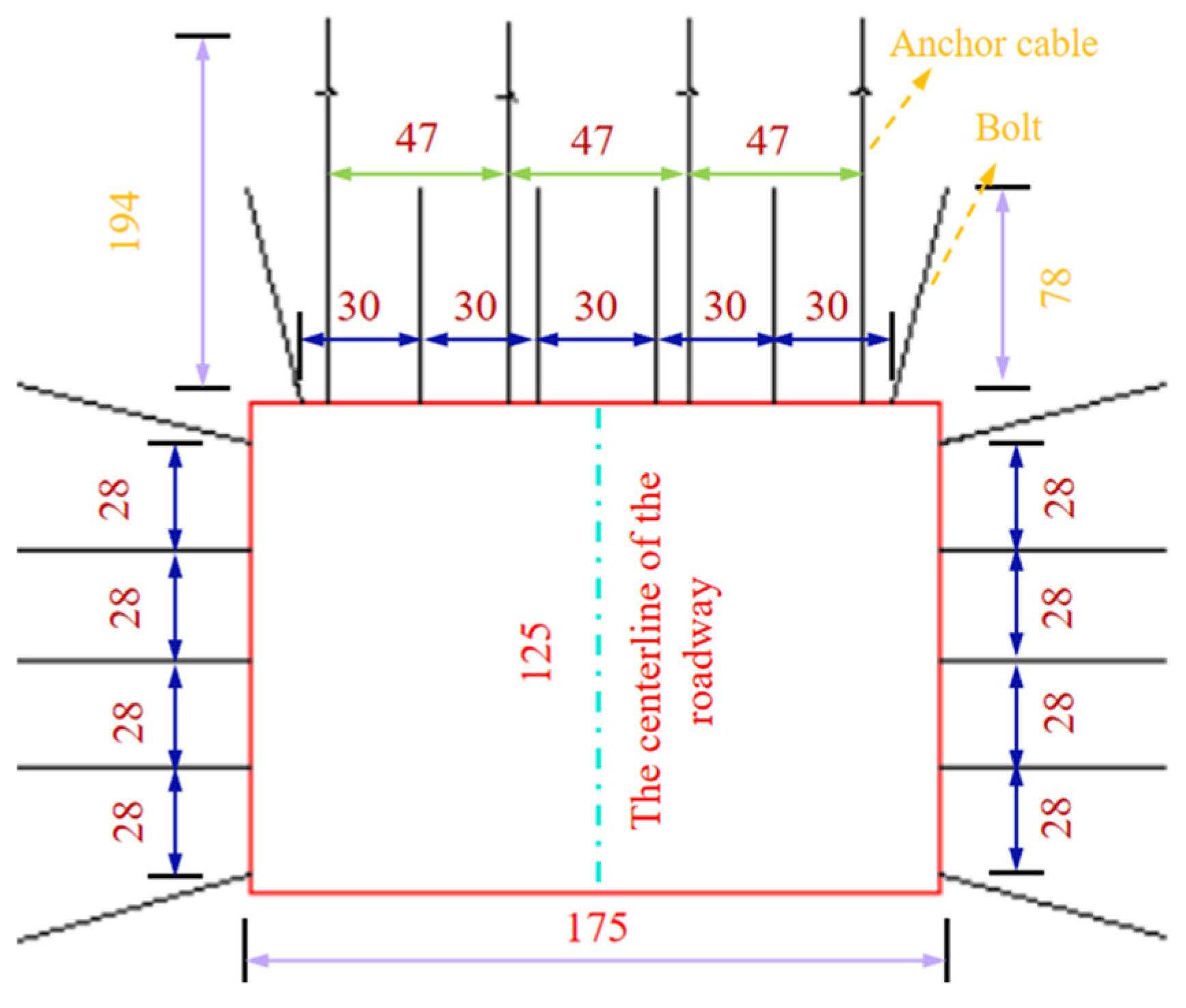
Model roadway support process parameters
According to the calculated geometric similarity ratio, a threaded rod with a length of 7.8 cm is selected for the bolt, a steel wire rope with a length of 19.4 cm is selected for the anchor cable, the spacing between bolts on the roof is 3 cm × 3 cm, the spacing between the rib bolts is 2.8 cm × 3 cm, and the spacing between anchor cables is 4.7 cm × 3 cm. The tray is made of processed steel sheets, and the anchoring agent is epoxy resin. The distance between the bolt support and the front end of the model roadway in the first stage is 3–6 cm. The remaining anchor bolt support (Stage II) lags behind the front end by 42–45 cm, and anchor cable support (Stage III) lags behind by 69–72 cm. The support section of the model roadway is shown in Figure 10.
(2)
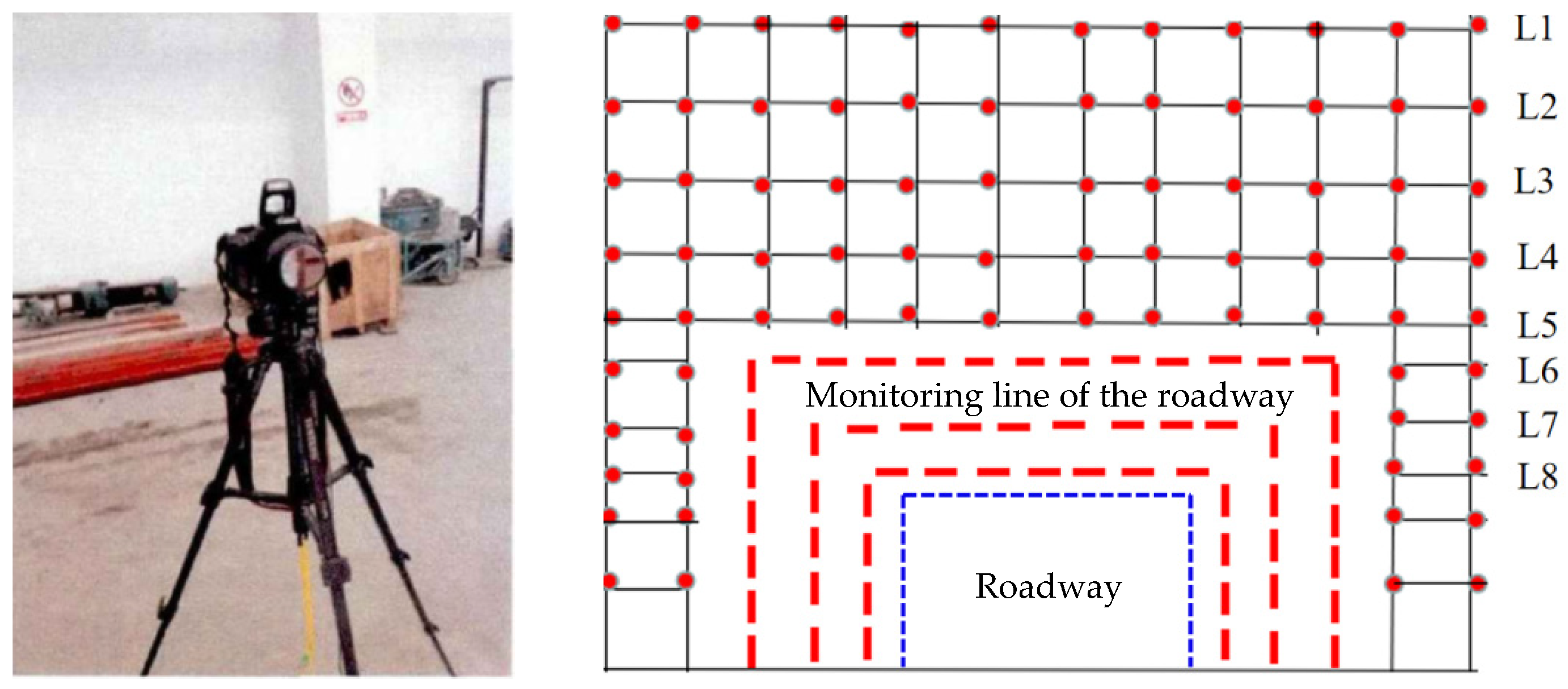
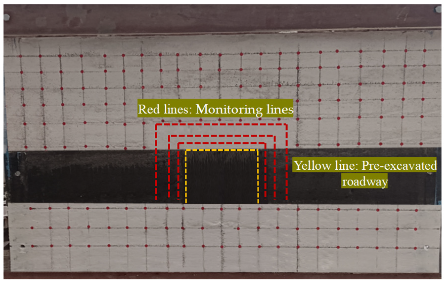
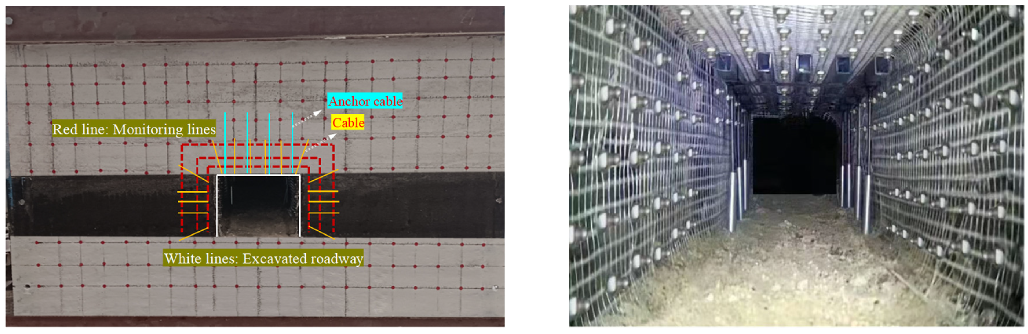
Stress and displacement monitoring
In order to obtain the stress changes and deformation laws of the roadway roof, pressure boxes are arranged above the roadway roof for stress monitoring. Three rows of stress monitoring sections are arranged in the direction of the roadway, with two points arranged in each row, for a total of six stress monitoring points. They are located 0–3 cm (initial support area), 42–69 cm (secondary reinforcement support area of the roof and rib), and 69–90 cm (permanent support area) away from the excavation head. Three displacement measurement lines are arranged around the roadway, with the remaining lines increasing every 5 cm in the vertical direction. One Nikon-550D camera is used in conjunction with a WEA-Qc8 intelligent high-definition camera to adjust the monitoring angle and monitor the displacement of the model surface and the roof inside the roadway. After the monitoring is completed, the captured observation points are imported into Getedate V2.25 software for processing. The layout of displacement measurement lines for the surrounding rock of the roadway is shown in Figure 11.
(3)
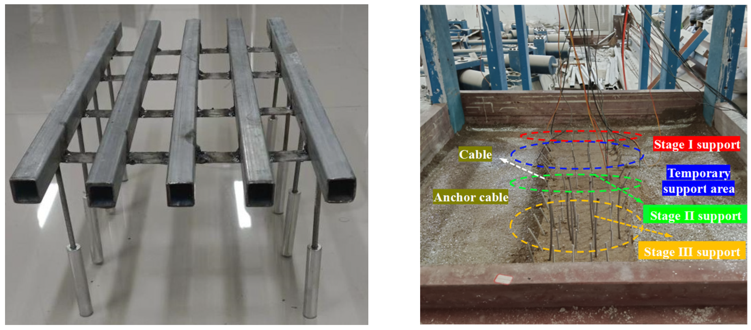
Model making and loading process
(i) The rock layer laying work should be carried out according to the rock layer ratio shown in Table 1. During this process, a long wooden strip wrapped with sealing film and coated with butter on all sides should be pre-embedded at the roadway position as the roadway model, and bolts, anchor cables, and pressure boxes should be pre-embedded. After the anchor rods and anchor cables are buried, an appropriate amount of mixed epoxy resin adhesive and epoxy curing agent (AB) should be placed at the end of the bolt and anchor cable as a simulated anchoring agent. The temporary support equipment is made of square steel pipes, nut columns, and matching high-strength threaded rods, as shown in Figure 12.
(ii) After the model is laid and left to air-dry for 7 days, remove the baffle is removed and natural air-drying continues for 14 days. Then, displacement measurement lines are arranged around the front surface of the model roadway position. The main view of the 3D physical similarity model is shown in Figure 13.
(iii) The model loading value is:
q m = ρ p g H h p ρ q g h q α p
Based on the above calculation, the compensation load applied above the roadway model is 0.33 MPa, and the cross-sectional area at the top of the model is 1.1 m2. A step-by-step loading method is adopted to achieve the failure law of the model roadway roof under different stress loading conditions and its impact on the supporting bearing body. When the original rock stress is applied above the model roadway, excavation of the frontal coal body (extraction of wooden strips) begins, and temporary support models are taken out to supplement the anchor mesh and cable support of the model roadway, as shown in Figure 14.
According to the stress distribution characteristics during the mining period of the roadway, the stress concentration factors are taken as K = 1.3 and K = 1.5. The vertical loading scheme above the similar model is shown in Table 3.

4. Test Results and Analysis

4.1. Evolution of Roof Stress and Displacement
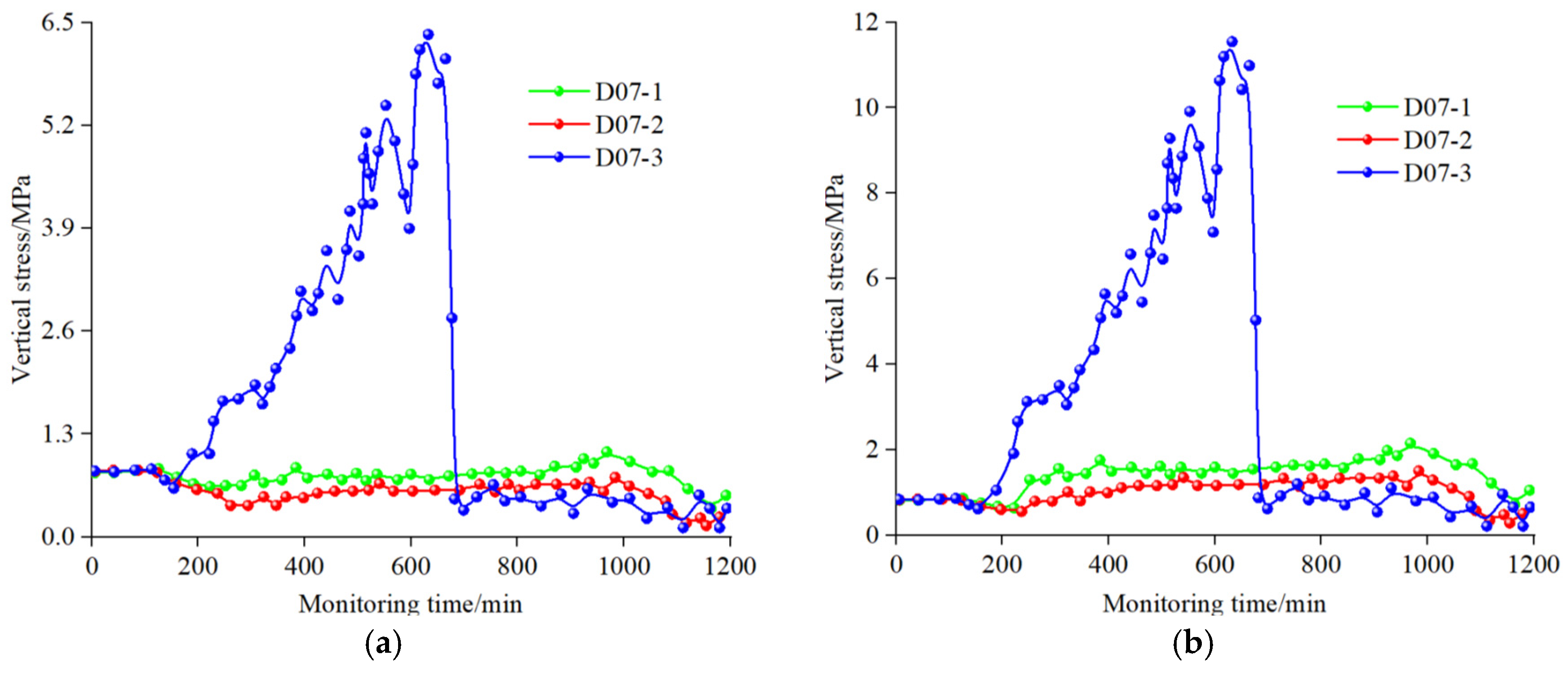
(1)
Evolution of roof stress
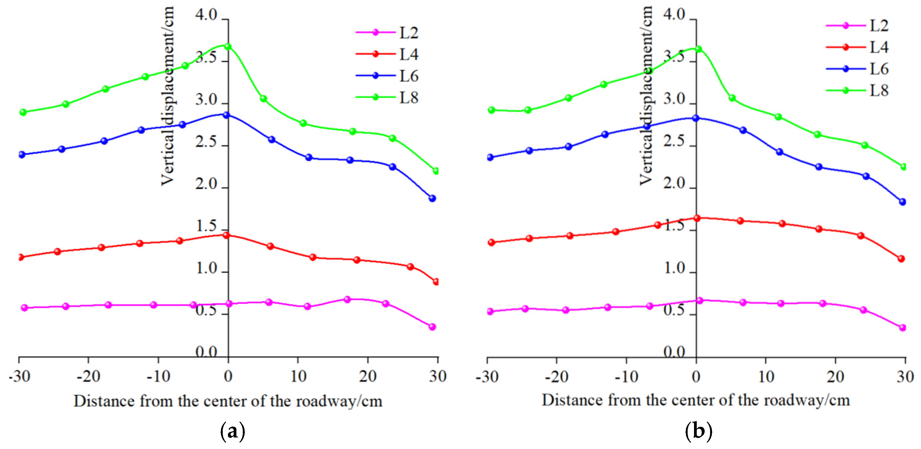
The data collected from the pressure box are analyzed, mainly exploring the stress variation law of the roof under staged support conditions. The vertical pressure–time relationship curves of measuring points in the permanent support areas (D07-1 and D11-1), secondary support areas (D07-2 and D11-2), and initial support areas (D07-3 and D11-3) 5 cm and 15 cm above the roadway roof in different support areas are shown in Figure 14. The pressure box collects data every 15 min, which are arranged on the same horizontal line. From the figure, it can be seen that the vertical pressure–time relationship curve of the roof mainly includes three stages, namely the (1) preloading stage, (2) excavation stage, and (3) mining depth increase stage.
According to the analysis in Figure 15, the vertical stress–time relationship curves of the roof during the entire loading period can be divided into three stages. The first stage is the preloading stage, and before loading, the stress range of the roof is 0.74–1.35 MPa. After loading, data recording began, and the vertical pressure on the roof increased rapidly in a “stepped” manner. The main reason was that the loading process was non-constant-velocity loading. After 2 h of loading, the vertical stress range of the roof was 2.31–2.54 MPa, and within 1 h of stabilization, the vertical stress of the roof remained stable. The second stage is the unloading stage of roadway excavation, where the surrounding rock degenerates from a three-dimensional stress state to a plane stress state, relieving the constraint on the roof above the roadway. The vertical stress of the roof at each measuring point begins to rapidly decrease, but the reduction rate varies greatly. The D07-3 and D11-3 measuring points are located 5 cm and 15 cm directly above the roof in the initial support area, with the largest reduction rates of 71.8% and 59.3%, respectively. The decrease in measurement points D07-2 and D11-2 was 62.8% and 41.5%, respectively. The vertical stress reduction amplitudes of the roof at measuring points D07-1 and D11-1 were the smallest, at 34.7% and 25.4%, respectively, while the vertical stress reduction amplitude of the roof at measuring point D07-3 in the temporary support area was the most significant. After loading for 2 h, the simulated mining depth continues to increase. Due to the excavation of the roadway, the stress state of the surrounding rock changes from a three-dimensional stress state to a two-dimensional stress state, the roof of the roadway gradually fractures, the coal shoulder angle fractures, and the peak stress of the surrounding rock gradually shifts outward. In the stage of mining influence, due to further excavation of the coal seam in front of the roadway, the spatial effect of the excavation face was relieved, and the roof collapsed in the form of tensile failure. At the measuring points within the affected range of the roadway, the vertical stress of the roof decreased again.
(2)
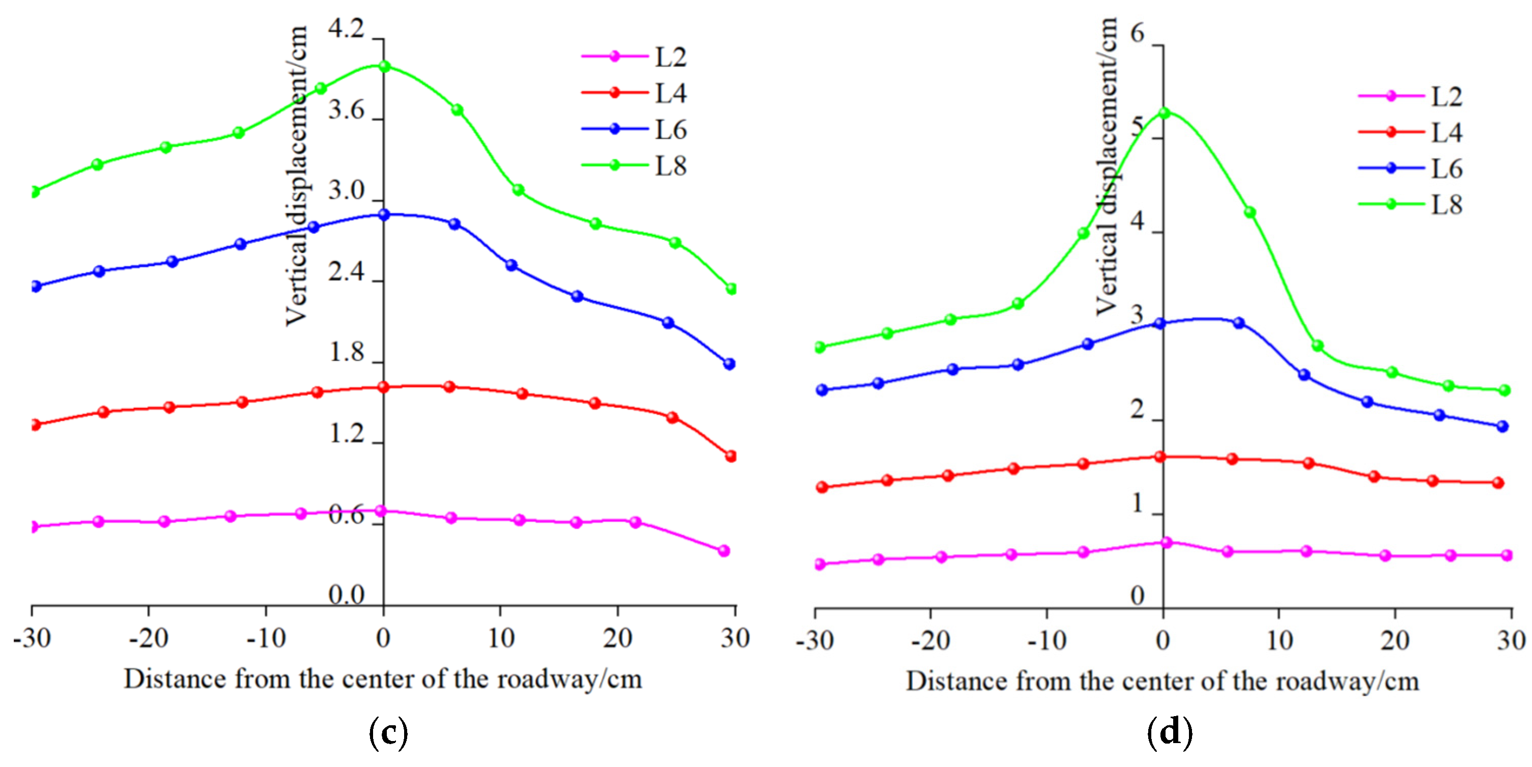
Evolution of roof displacement
The absolute displacement of the roadway reflects the direct support effect, while the relative displacement reflects the degree of rock damage. We used a high-definition digital camera to capture data from various displacement observation points in the images, imported the measured images into Getedate V2.25 software, analyzed their coordinate points, and obtained the horizontal and vertical coordinates of the measuring points in the roadway at different loading depths during the loading process, in order to analyze the displacement of individual measuring points around the roadway. The displacement distribution curves of the four displacement measurement lines mentioned above are shown in Figure 16. The horizontal axis in the figure represents the relative position to the center of the roadway, and the four monitoring lines are L1, L4, L6, and L8, located 22 cm, 12 cm, 6 cm, and 2 cm above the roof, respectively. Analysis shows that during the initial loading stage, the load acting on the roof is relatively small, and the vertical displacement of the roof remains roughly synchronized and sinks, manifested as the overall sinking of the compacted model. As the vertical stress increases, the displacement curve of the roof basically shows a basin-shaped settlement trend, and the curves all evolve into a “V” shape. The farther away from the center of the roadway, the smaller the subsidence of the roof, and the maximum subsidence point occurs at the center of the roadway.
When the vertical pressure is loaded to 36.3 kN, the shallower part of the roadway has the largest subsidence, about 3.5 cm, and the further away from the roadway, the smaller the subsidence, reaching as low as 0.6 cm. When loaded to 39.93 kN, the subsidence of the same horizontal roof is basically the same as in Figure 15a, indicating that the model roadway is compacted as a whole at this stage. When loaded to 54.45 kN, the deflection and settlement of the roof increase, indicating that the development of roof delamination cracks is relatively fast.

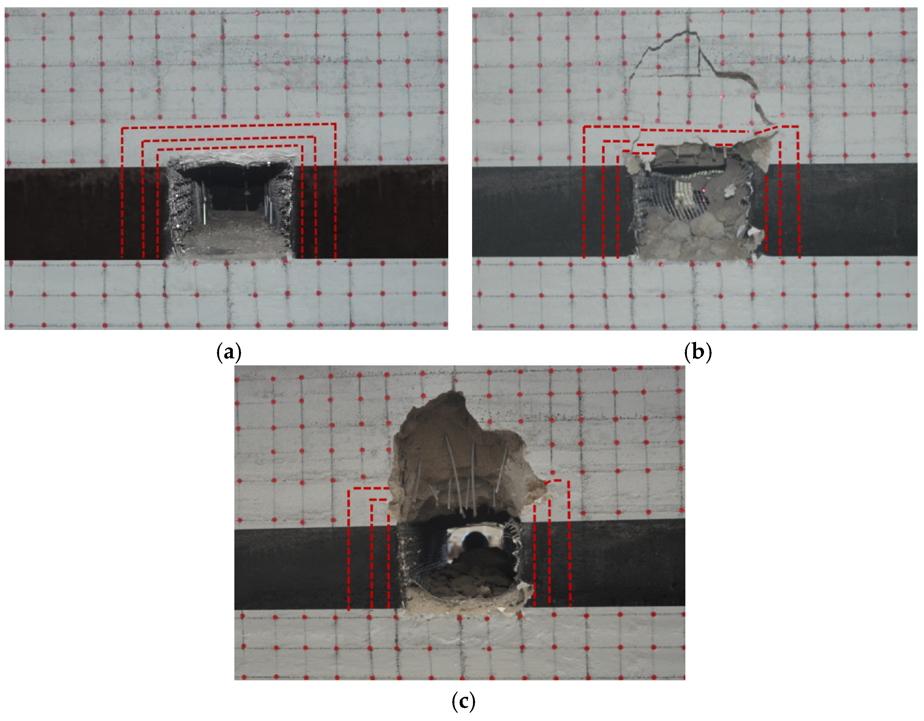
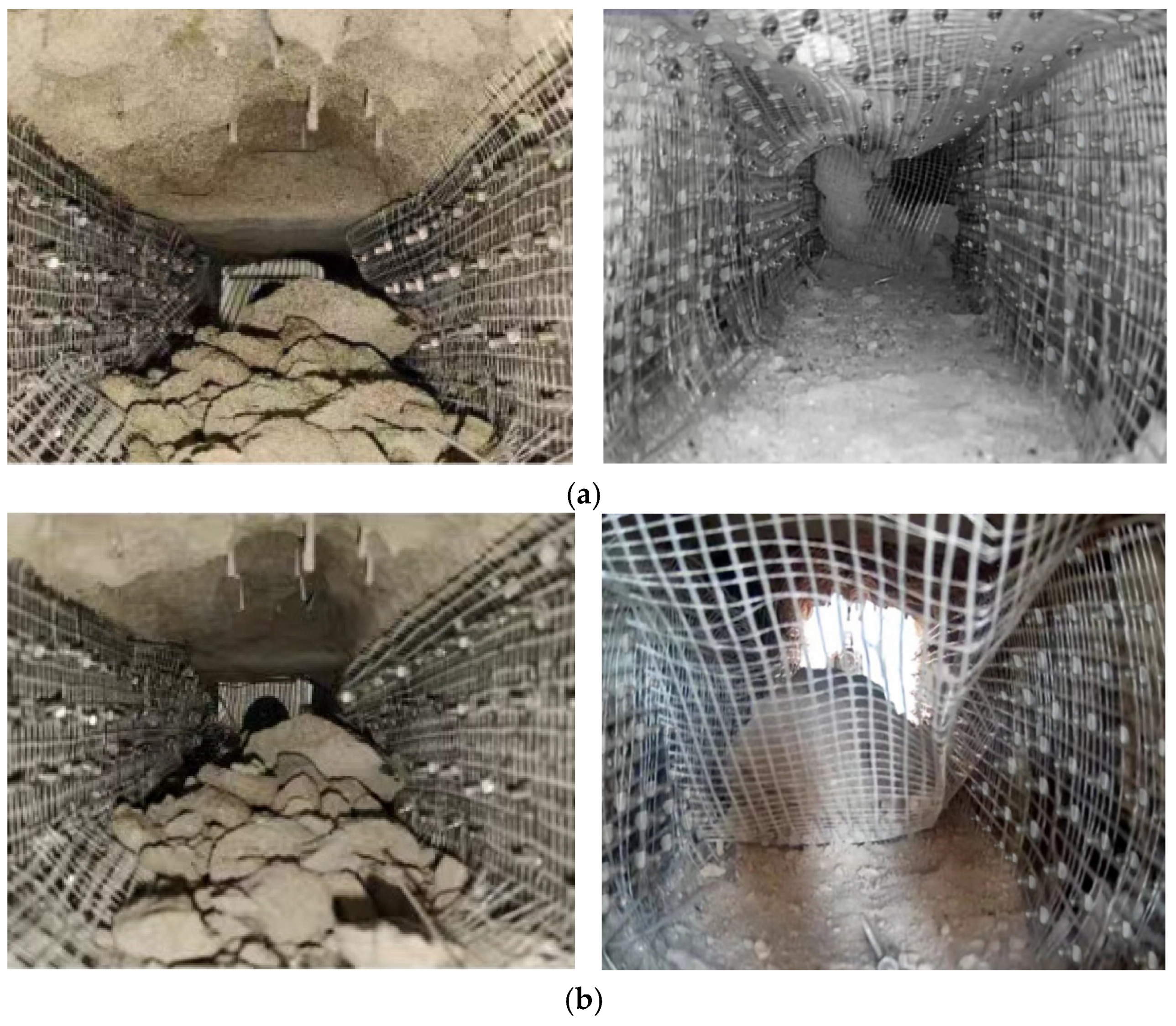
4.2. Analysis of Roof Failure Characteristics

The whole destruction process of the roadway roof is recorded by camera and intelligent monitoring instruments. As the axial load continues to increase, cracks first appear around the roadway roof and slightly sink, and then the cracks gradually expand and penetrate, leading to instability and failure of the roadway roof, as shown in Figure 17 and Figure 18. First, 5.98 kN is loaded above the model, equivalent to a mining depth of 100 m. After stabilizing for 1 h, loading is continued to 11.95 kN, equivalent to a mining depth of 200 m. After stabilizing for 1 h, simulation of the process of roadway excavation begins. The long wooden strips are pulled out of the roadway model, 20 cm of coal is reserved in front of the head, and work begins on laying anchor nets, installing anchor washers, tightening nuts, and arranging temporary supports behind the head. When loaded to 16.3 kN, the converted mining depth is 300 m. Due to the anchor net cable support applied to the roadway, the stability of the roof is good, and there are no obvious delamination cracks or roof subsidence phenomena. However, after the excavation of the roadway, the internal cracks of the low-level roof behind the temporary support begin to develop due to changes in the deformation space of the roof. When loaded to 36.3 kN, converted to a mining depth of 610 m, and stabilized for 1 h, due to the lower strength of the low-level roof, there were slight signs of sinking behind the low-level roof when bearing a larger load from the upper part. There were also obvious cracks on both sides above the roof, and the roof tended to collapse downwards. When loaded to 47.19 kN and converted to mining stress K = 1.3 times, the roadway roof continued to sink, with more and wider cracks above, and transverse cracks and delamination appeared. However, under the support of anchor mesh cables, no overall collapse occurred. When loaded to 54.45 kN and converted to mining stress K = 1.5 times, the middle part of the model roadway in the axial direction broke and cracks penetrated, resulting in overall collapse.

5. Conclusions

(1) Based on the spatiotemporal effect of excavation face, the relationship between the release of the surrounding rock stress and the cyclic advancement distance of excavation face is analyzed, and the evolution law of surrounding rock release stress under the spatial effect of excavation face is obtained. Combined with the complex stress state in the actual site, a dynamic staged control principle of surrounding rock based on “high-strength passive support near the excavation face, active support of rear bolts and anchor cables” is proposed.
(2) After the excavation of the roadway, the high-strength temporary passive support is adopted in the front area of the excavation, which greatly limits the deformation space of the roof, thereby improving the bearing stress state of the roof, constraining the development of cracks in the roof, and increasing the spatial effect range of the excavation face.
(3) When the axial load was loaded to a mining stress of 47.19 kN, due to the release of high-strength constraints on the roof, the vertical stress on the roof rapidly decreased, the development and widening of roof cracks increased, and the subsidence of the roof increased to 4.1 cm, but no overall collapse occurred. When the axial load reaches 54.45 kN, cracks develop and penetrate, resulting in delamination and support failure and leading to instability and collapse of the roof.

Author Contributions

All authors contributed to this article. Formal analysis, investigation, funding acquisition, S.Y.; methodology, resources, funding acquisition, L.M.; data curation, W.W. and S.H. All authors have read and agreed to the published version of the manuscript.

Funding

This research was funded by the Autonomous Projects of Key Laboratory of Xinjiang Coal Resources Green Mining (Xinjiang Institute of Engineering), Ministry of Education (KLXGY-Z2509), and the National Natural Science Foundation of China (52464015).

Data Availability Statement

The original contributions presented in the study are included in the article, further inquiries can be directed to the corresponding author.

Acknowledgments

All authors contributed to this article. We would like to thank those who reviewed and modified the manuscript.

Conflicts of Interest

Author Weilong Wei was employed by the Yushuling Coal Mine Co., Ltd., Xinjiang Yuneng Investment Group Co., Ltd. The remaining authors declare that the research was conducted in the absence of any commercial or financial relationships that could be construed as a potential conflict of interest.

References

  1. Cheluszka, P. Numerical studies of the dynamics of the roadheader equipped with an automatic control system during cutting of rocks with different mechanical properties. Energies 2021, 14, 7353. [Google Scholar] [CrossRef]
  2. Wang, E.Y.; Chen, G.B.; Yang, X.J.; Zhang, G.F.; Guo, W.B. Study on the failure mechanism for coal roadway stability in jointed rock mass due to the excavation unloading effect. Energies 2020, 13, 2515. [Google Scholar] [CrossRef]
  3. Wang, J.H. China mechanized road header status and bolt support technology in mine seam roadway. Coal Sci. Technol. 2004, 1, 6–10. [Google Scholar] [CrossRef]
  4. Wang, H.; Wang, J.L.; Zhang, X.F. Theory and technology of integrated and efficient excavation and anchoring. J. China Coal Soc. 2020, 45, 2021–2030. [Google Scholar] [CrossRef]
  5. Kaiser, P. Phenomenological model for rock with time dependent strength. Int. J. Rock Mech. Min. Sci. Geomech. 1985, 18, 153–165. [Google Scholar] [CrossRef]
  6. Guo, H.; Ji, M.; Li, H.; Zhang, K.; Wang, H.; Liang, A. Research and application on support technology of coal seam roadway with high stress. J. Mines Met. Fuels 2019, 67, 82–89. [Google Scholar]
  7. Hayati, A.N.; Ahmadi, M.M.; Hajjar, M.; Kashighandi, A. Unsupported advance length in tunnels constructed using New Austrian Tunnelling Method and ground surface settlement. Int. J. Numer. Anal. Methods Geomech. 2013, 37, 2170–2185. [Google Scholar] [CrossRef]
  8. Jia, H.S.; Ma, N.J.; Zhu, Q.K. Mechanism and control method of wing leaf plastic zone penetration induced collapse in roadway roof. J. China Coal Soc. 2016, 41, 1384–1392. [Google Scholar]
  9. Jing, W.; Zhou, J.; Yuan, L.; Jin, R.C.; Jing, L.W. Deformation and failure mechanism of surrounding rock in deep soft rock tunnels considering rock rheology and different strength criteria. Rock Mech. Rock Eng. 2024, 57, 545–580. [Google Scholar] [CrossRef]
  10. Tang, B.; Mao, A.; Li, T.G.; Cheng, H.; Tao, W.B.; Liu, B.; Hou, J.L. Mechanical behaviors of steel segment support structures for TBM-excavated coal mine tunnels: Experimental and numerical study. Int. J. Civ. Eng. 2024, 23, 345–359. [Google Scholar] [CrossRef]
  11. Yasitli, N.E. Numerical modeling of surface settlements at the transition zone excavated by New Austrian Tunneling Method and Umbrella Arch Method in weak rock. Arab. J. Geosci. 2013, 6, 2699–2708. [Google Scholar] [CrossRef]
  12. Aygar, E.B. Evaluation of new Austrian tunnelling method applied to Bolu tunnel’s weak rocks. J. Rock Mech. Geotech. Eng. 2020, 12, 541–556. [Google Scholar] [CrossRef]
  13. Wibisono, D.Y.; Gutierrez, M.; Majumder, D. Experimental investigation of tunnel damage and spalling in brittle rock using a true-triaxial cell. Int. J. Rock Mech. Min. Sci. 2024, 182, 105884. [Google Scholar] [CrossRef]
  14. Chu, X.W.; Wu, Y.Z.; Wu, Z.G.; Hao, D.Y.; Feng, Y.L.; Li, W.Z.; Meng, X.Z. Characteristics of roof deformation in excavating face and determination method of reasonable non-support distance. J. Min. Saf. Eng. 2020, 37, 908–917. [Google Scholar] [CrossRef]
  15. Zhou, H.; Hu, S.C.; Lu, J.J.; Wang, Z.C.; Zhang, C.Q. In situ testing of surrounding rock deformation and failure during the entire process of coal mine deep well roadway excavation. Geotech. Mech. 2015, 36, 3523–3530. [Google Scholar] [CrossRef]
  16. Sofianos, A.I.; Kapenis, A.P. Effect of strata thickness on the stability of an idealized bolted underground roof. Mine Plan. Equip. Sel. 1996, 1996, 275–279. [Google Scholar]
  17. Zhao, M.Z. Stability Mechanism and Safety Control Technology of Compound Roof in Fully Mechanized Coal Roadway of Zhaozhuang Mine; China University of Mining and Technology: Xuzhou, China, 2022. [Google Scholar]
  18. Yu, Y.; Wang, X.Y.; Bai, J.B.; Zhang, L.Y.; Xia, H.C. Deformation mechanism and stability control of roadway surrounding rock with compound roof: Research and applications. Energies 2020, 13, 1350. [Google Scholar] [CrossRef]
  19. Guo, Y.X. Linkage Effect of Surrounding Rock Layers in Deep Large Section Coal Roadway and Roof Support Control Technology; China University of Mining and Technology: Xuzhou, China, 2024. [Google Scholar]
  20. Wang, B. Research on graded support and rapid excavation technology of bolt(cable) in coal mine roadway. Xi’an Univ. Sci. Technol. 2020. [Google Scholar] [CrossRef]
  21. Sun, J. Progress in Rock Rheological Mechanics and Its Engineering Applications. J. Rock Mech. Eng. 2007, 6, 1081–1106. [Google Scholar]
  22. Zhou, Z.L.; Tan, Z.S.; Li, L.F.; Lei, K. Research on the dynamic interaction mechanism between surrounding rock and support in TBM tunnel. J. Railw. Sci. Eng. 2024, 22, 284. [Google Scholar] [CrossRef]
  23. Hoek, E.; Brown, E.T. Underground Excavations in Rock; Institution of Mining and Metallurgy: London, UK, 1980. [Google Scholar]
  24. Oreste, P.P. Analysis of structural interaction in tunnels using the covergence-confinement approach. Tunn. Undergr. Space Technol. 2003, 18, 347–363. [Google Scholar] [CrossRef]
Figure 1. The variation law of stress release in surrounding rock.
Processes 13 01003 g001
Figure 2. Strength and stress states of surrounding rock before and after excavation.
Processes 13 01003 g002
Figure 3. Equivalent mechanical model based on spatial effects of excavation face. (a) Virtual support force alone. (b) The combined effect of support reaction force and virtual support force. (c) Balance between surrounding rock and support.
Processes 13 01003 g003
Figure 4. Principle curve of surrounding rock support interaction.
Processes 13 01003 g004
Figure 5. Construction process of coal mine roadway.
Processes 13 01003 g005
Figure 6. Relationship curve of the stiffnesses of the support structure.
Processes 13 01003 g006
Figure 7. Comprehensive bar chart.
Processes 13 01003 g007
Figure 8. Cross-section of roadway support. (a) Radial section. (b) Axial section.
Processes 13 01003 g008
Figure 9. The process of making samples. (a) Samples production. (b) Cylindrical samples.
Processes 13 01003 g009
Figure 10. Model roadway support section.
Processes 13 01003 g010
Figure 11. Roof displacement observation system.
Processes 13 01003 g011
Figure 12. Layout of axial graded support for roadway.
Processes 13 01003 g012
Figure 13. 3D physical similarity model.
Processes 13 01003 g013
Figure 14. Model roadway surface and internal support structure.
Processes 13 01003 g014
Figure 15. Vertical stress–time relationship curves of roadway roof. (a) 5 cm measuring point above the roadway. (b) 15 cm measuring point above the roadway.
Processes 13 01003 g015
Figure 16. Displacement curves of the roof on the surface of the model: (a) at load 36.3 kN; (b) at load 39.93 kN; (c) at load 47.19 kN; (d) at load 54.45 kN.
Processes 13 01003 g016aProcesses 13 01003 g016b
Figure 17. The entire process of roof failure under graded loading: (a) at load 36.3kN; (b) at load 47.19kN; (c) at load 54.45kN.
Processes 13 01003 g017
Figure 18. The process of roof failure inside the roadway under graded loading: (a) at load 47.19 kN; (b) at load 54.45 kN.
Processes 13 01003 g018
Table 1. Physical and mechanical indicators of proportioned specimens.
Rock Layer NameRatio Number
(Sand:Lime:Gypsum)
Average Compressive Strength of Samples/MPaRock Compressive Strength/MPa
Fine sandstone6:5:51.19254.84
Sandy mudstone7:7:30.67431.45
Coal10:5:50.1635.49
Mudstone8:6:40.35716.42
Siltstone9:5:51.15253.41
Table 2. Physical and mechanical parameters of rock strata and similar proportions.
NO.LithologyThickness/mDensity/kg·m−3LayersRatio NumberWeight of Each Layer/kg
SandLimeGypsumWater
10Sandy mudstone15.022807773167.916.87.219.2
9Fine sandstone5.02630565588.67.47.410.3
811-3 coal0.515001105526.81.31.32.9
7Mudstone0.91690286426.51.91.32.9
611-2 coal4.013804105549.32.52.55.4
5Mudstone2.01690286459.14.42.96.6
411-1 coal0.514001105525.01.31.32.8
3Mudstone0.81690186447.23.52.45.3
2Charcoal mudstone0.516001123729.00.71.73.1
1Sandy mudstone10.822804773211.621.29.12.4
Table 3. Vertical stress loading scheme for similar models.
Loading LevelTime IntervalVertical Loading
Step 11 h (Preloading)5.98 kN
Step 21 h (Preloading)11.95 kN
Step 31 hWait for the pressure to stabilize and start extracting the wooden strips
Step 42 h16.3 kN
Step 52 h23.9 kN
Step 62 h29.8 kN
Step 72 h36.3 kN
Step 81 hExcavate the coal seam in front of the roadway
Step 92 h36.3 × 1.3 kN (Mining impact)
Step 102 h36.3 × 1.5 kN (Mining impact)
Disclaimer/Publisher’s Note: The statements, opinions and data contained in all publications are solely those of the individual author(s) and contributor(s) and not of MDPI and/or the editor(s). MDPI and/or the editor(s) disclaim responsibility for any injury to people or property resulting from any ideas, methods, instructions or products referred to in the content.

