Article

Thermodynamic Simulations of a Single-Stage Absorption Heat Transformer Utilizing Low-Temperature Waste Heat (60 °C)

1
CEFT/ALICE - Faculty of Engineering, University of Porto, Rua Dr. Roberto Frias, 4200-465 Porto, Portugal
2
Department of Mechanical Engineering - Faculty of Engineering, University of Porto, Rua Dr. Roberto Frias, 4200-465 Porto, Portugal
*
Author to whom correspondence should be addressed.
Processes 2025, 13(4), 1001; https://doi.org/10.3390/pr13041001
Submission received: 18 February 2025 / Revised: 21 March 2025 / Accepted: 25 March 2025 / Published: 27 March 2025

Abstract

:
This study focuses on the theoretical performance of a single-stage absorption heat transformer (SSAHT) using the working pair H2O/LiBr for low-temperature waste heat recovery. A thermodynamic model was implemented in Engineering Equation Software (EES) considering a waste heat temperature of 60 °C in a small-scale SSAHT. A sensitivity analysis was performed where important system parameters were varied, including the inlet temperatures, mass flow rates, and solution heat exchanger effectiveness. Their impact on different AHT performance parameters ( C O P , E C O P , G T L , and F R ) was evaluated, and these results provided practical guidelines that were utilized to optimize the SSAHT operating conditions.

1. Introduction

Waste heat recovery has the potential to provide substantial amounts of useful energy, reducing the reliance on primary energy sources. In industry, heat recovery technologies can be implemented to upgrade low-exergy waste thermal energy, enabling its reuse in subsequent processes or neighboring industrial facilities. Among these technologies, absorption heat transformers (AHTs), also known as type II absorption heat pumps, stand out for their ability to upgrade low-temperature waste heat to higher, more useful temperature levels. An important advantage of AHT systems over conventional vapor compression heat pumps is related to their negligible electricity consumption—up to two orders of magnitude lower than their vapor compression counterparts with an equivalent capacity. Despite the promising potential of AHTs in thermal energy recovery, their application remains scarce [1]. This can be attributed to the economic and technical challenges of recovering low-grade thermal energy, which are obstacles to their implementation.
Several researchers have conducted thermodynamic analyses to evaluate the performance of AHTs, utilizing both the traditional working pair H2O/LiBr and alternative solutions. For applications employing the H2O/LiBr pair, existing studies have predominantly focused on waste heat temperatures exceeding 70 °C [2], while studies using lower temperatures are scarce [3,4]. This trend likely stems from the combination of two factors: the limited economic appeal of recovering low-temperature waste heat and the increased operational challenges associated with the vacuum pressures required for such cycles. Lower waste heat temperatures (30–70 °C) have been used with alternative working pairs such as NH3/H2O or H2O/Carrol [5,6,7]. However, given that, at present, H2O/LiBr is the industry-standard working pair for AHT applications [1], studies using this mixture at lower temperatures are also relevant.
In AHTs, changes in the input parameters impact all other variables, given the interdependency between all components of the cycle. Several studies have analyzed the influence of the input parameters on the performance of AHTs [8,9,10,11,12]. However, no variable sensitivity analysis has been performed for an AHT operating at such a low temperature (60 °C) with the working pair H2O/LiBr. This lower temperature range is relevant for multiple applications, ranging from solar energy [13,14,15] and water purification [3,4,16] to industrial waste heat recovery. Moreover, this type of analysis is a key step in prototype design, as it enables the optimization of operating parameters based on the specific goals or restrictions of a given application.
In this study, a waste heat stream (water) at a temperature of 60 °C and atmospheric pressure was considered because it represents a common operating condition in low-grade waste heat recovery applications. Although lower temperatures (for example, 55 °C) may occur in some applications, 60 °C was selected as it was low enough to test the limits of thermal upgrading with the H2O/LiBr pair, while also being high enough to prevent issues related to the associated low system pressures.

2. Materials and Methods

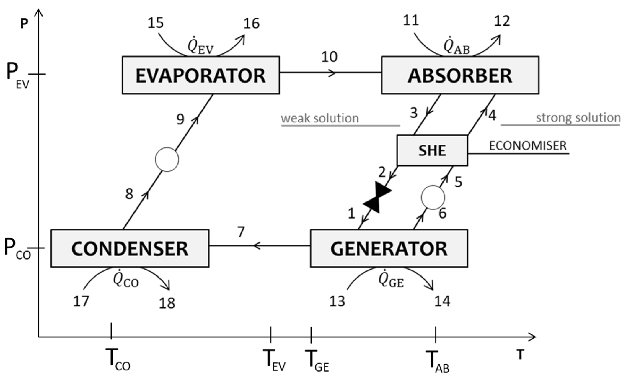
2.1. Single-Stage Absorption Heat Transformers

Single-stage absorption heat transformers (SSAHTs) represent the simplest configuration of absorption heat transformers, including a generator, condenser, evaporator, absorber, and solution heat exchanger (optional, but commonly used), two pumps, and an expansion valve [12], as depicted in Figure 1. In these systems, two different pressure levels ( P EV and P CO ) are used, corresponding to the refrigerant’s (H2O) saturation pressure at the temperature of the evaporator and condenser, respectively. The waste heat is introduced in the evaporator and generator, whereas useful heat at a higher temperature is recovered in the absorber. In the evaporator, the waste heat Q ˙ EV promotes the vaporization of the refrigerant. The vaporized refrigerant is then absorbed by a strong solution (characterized by a higher concentration of absorbent) in an exothermic process that releases useful heat at a higher temperature Q ˙ AB . The resulting weak solution (with a lower absorbent concentration) transfers its heat to the strong solution using the solution heat exchanger, improving the overall efficiency. In the generator, additional waste heat Q ˙ GE is supplied to enable the desorption of the refrigerant from the absorbent. The refrigerant vapor is then directed to the condenser, releasing low-temperature heat Q ˙ CO as it condenses. The condensed refrigerant returns to the evaporator, completing the cycle. Meanwhile, the regenerated strong solution returns to the absorber to maintain the process.

2.2. Thermodynamic Model

The thermodynamic model of the SSAHT was implemented to analyze its performance in specific operating conditions, corresponding to low-temperature waste heat recovery. The modeling assumptions are summarized below and correspond to the standard practices in absorption system simulation [12,17].
  • The system is in a steady state;
  • The refrigerant vapor/liquid leaving the evaporator/condenser is saturated;
  • The expansion valve is adiabatic, and the pumps are isentropic;
  • The generator and condenser are at a lower pressure, while the evaporator and absorber are at a higher pressure;
  • There are no heat losses to the environment.
The mass balances were written for each component in the system, according to the general Equations (1) to (2).
m ˙ in = m ˙ out
m ˙ in x in = m ˙ out x out
where m ˙ i n and m ˙ out correspond to the mass flow rates (kg/s) and x in and x out to the mass ratio of LiBr in the solution at the inlet and outlet.
The energy balances in each heat exchanger were written as per Equation (3).
Q ˙ = m ˙ out h out m ˙ in h in
where Q ˙ is the heat transfer rate, and h in and h out (kJ/kg) are the specific enthalpies at the inlet and outlet.
The heat added/removed in the heat exchangers of the SSAHT (evaporator, absorber, condenser, and generator) can be calculated using Equation (4). This equation accounts for the sensible heat transfer based on the external circuits (streams 11 to 18, Figure 1).
Q ˙ = m ˙ c Δ T
The rate of heat transfer in a heat exchanger can be expressed as [18]
Q ˙ = U A Δ T m
Δ T m = F t Δ T ln = F t Δ T 0 Δ T L ln ( Δ T 0 Δ T L )
where U (W/(m2 °C)) is the overall heat transfer coefficient, A (m2) the heat transfer area, and Δ T m (°C) is the mean temperature difference between the two fluids flowing in the heat exchanger (Equation (6)). The latter can be calculated considering a correction factor F t ( F t 1 ) that depends on the geometry of the heat exchanger and the mean temperature differences at the inlet and outlet, Δ T 0 and Δ T L . In this model, F t was considered equal to 1, the value for a single-pass counterflow heat exchanger.
The pressures P were selected considering two different pressure levels within the SSAHT: the low pressure corresponds to the pressure at the condenser outlet (saturated liquid), and the high pressure corresponds to the pressure at the evaporator outlet (saturated vapor).
An adiabatic absorption model was used to calculate the highest temperature achieved in the absorber. This is because, in steady state, the temperature in the absorber is higher than either of the inlet temperatures ( T 4 and T 10 ) due to the exothermic absorption of the refrigerant in the absorbent. Therefore, the maximum temperature in the absorber was defined as the adiabatic saturation temperature, corresponding to the equilibrium temperature obtained by mixing the solution (stream 4) and the vapor (stream 10). The adiabatic model, as well as the full thermodynamic model for the SSAHT and its implementation in the software Engineering Equation Solver (EES), is explained in [12].
EES is a software tool that enables the solution of complex nonlinear equation systems. In this study, EES was used to solve the mass and energy balances that govern the SSAHT cycle, while integrating its extensive thermophysical properties database to simulate the behavior of the H2O/LiBr working pair in different operating conditions. The model was first validated by comparing the results obtained at the same operating conditions described in Herold et al. [12].
Some important performance parameters were calculated, including the coefficient of performance C O P , the exergetic coefficient of performance E C O P , the flow ratio F R , and the gross temperature lift G T L .
The C O P and E C O P are given by
C O P = Q ˙ AB Q ˙ GE + Q ˙ EV
E C O P = ( 1 T 0 / T 12 ) Q ˙ AB ( 1 T 0 / T 13 ) Q ˙ GE + ( 1 T 0 / T 15 ) Q ˙ EV
where T 0 , the reference temperature, was considered equal to 20 °C.
The gross temperature lift G T L was calculated as the difference between the temperature of the upgraded (useful) heat and the temperature of the driving (waste) heat, as adopted by most authors [1,5,19,20]:
G T L = T 12 T 15
The flow ratio (FR) corresponds to the ratio between the mass flow rate of the strong solution coming from the absorber m ˙ 13 and that of the refrigerant leaving the generator m ˙ 17 :
F R = m ˙ 3 m ˙ 7

3. Results and Discussion

3.1. Base Model Performance

In the base model, a waste heat stream (water at atmospheric pressure) with a temperature of 60 °C was considered. This low-temperature stream was used as the input to the generator ( T 13 ) and evaporator ( T 15 ). The simulation input parameters and the results obtained using the base model are shown in Table 1. The results show that, for a heating capacity Q ˙ AB of 6.9 kW, the system achieved a C O P of 0.49 and an E C O P of 0.58, delivering a G T L of 19.8 °C. The temperature of the product T 12 was calculated as 68.3 °C, which is higher than any of the inlet temperatures in the absorber. This elevated temperature is a result of the exothermic absorption of the refrigerant, H2O, in the LiBr solution, releasing heat. Furthermore, the total pump work W ˙ required by the system is 0.27 W, which is negligible and highlights the potential of the SSAHT to upgrade waste heat with minimal energy requirements.

3.2. Sensitivity Analysis

This section presents a detailed sensitivity analysis, where key input parameters were varied—specifically, the inlet temperatures of the external streams ( T 11 , T 13 , T 15 , and T 17 ); the mass flow rate of the strong solution m ˙ 4 ; and the efficiency of the solution heat exchanger ε SHE . The effects of these variations on the performance of the SSAHT were quantified through plots of the C O P , E C O P , absorber heat transfer rate Q ˙ AB , gross temperature lift G T L , and flow ratio F R . In each scenario, only one specified parameter was varied, while all other inputs were constant at the values shown in Table 1.
The analysis of the results evidenced the complex interdependencies among the variables, with changes in one parameter influencing all other variables in the cycle. This feature, combined with the nonlinear nature of the model equations, makes interpreting the impact of individual parameters more challenging. Nonetheless, some insights are provided to explain some of the observed trends.

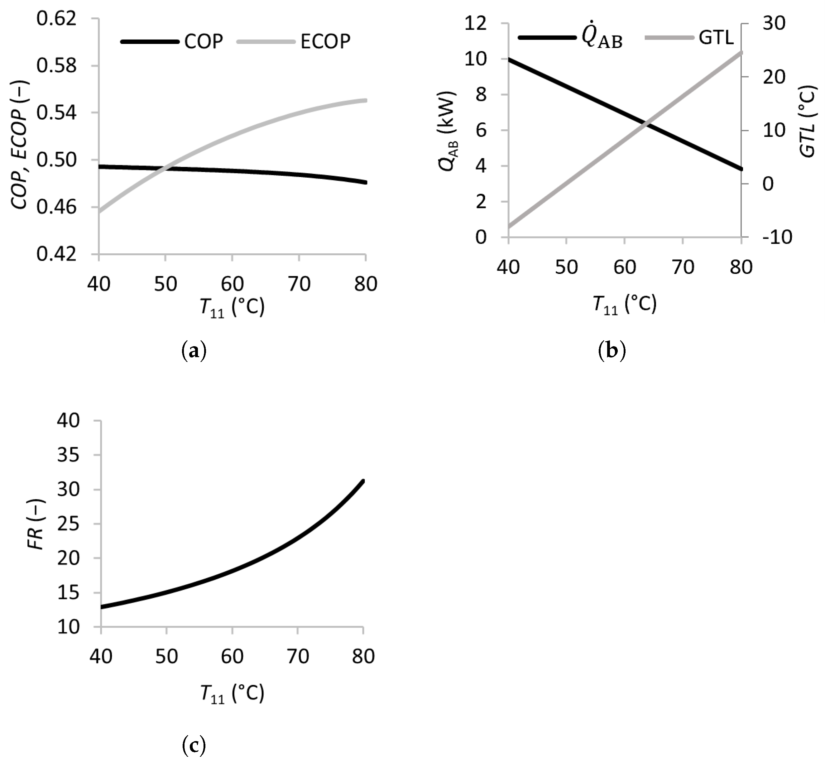
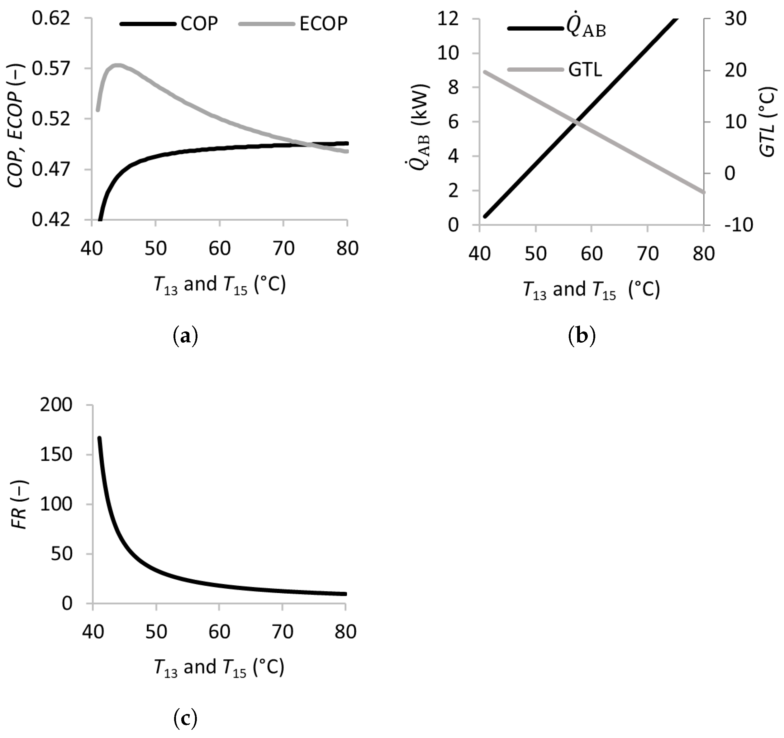
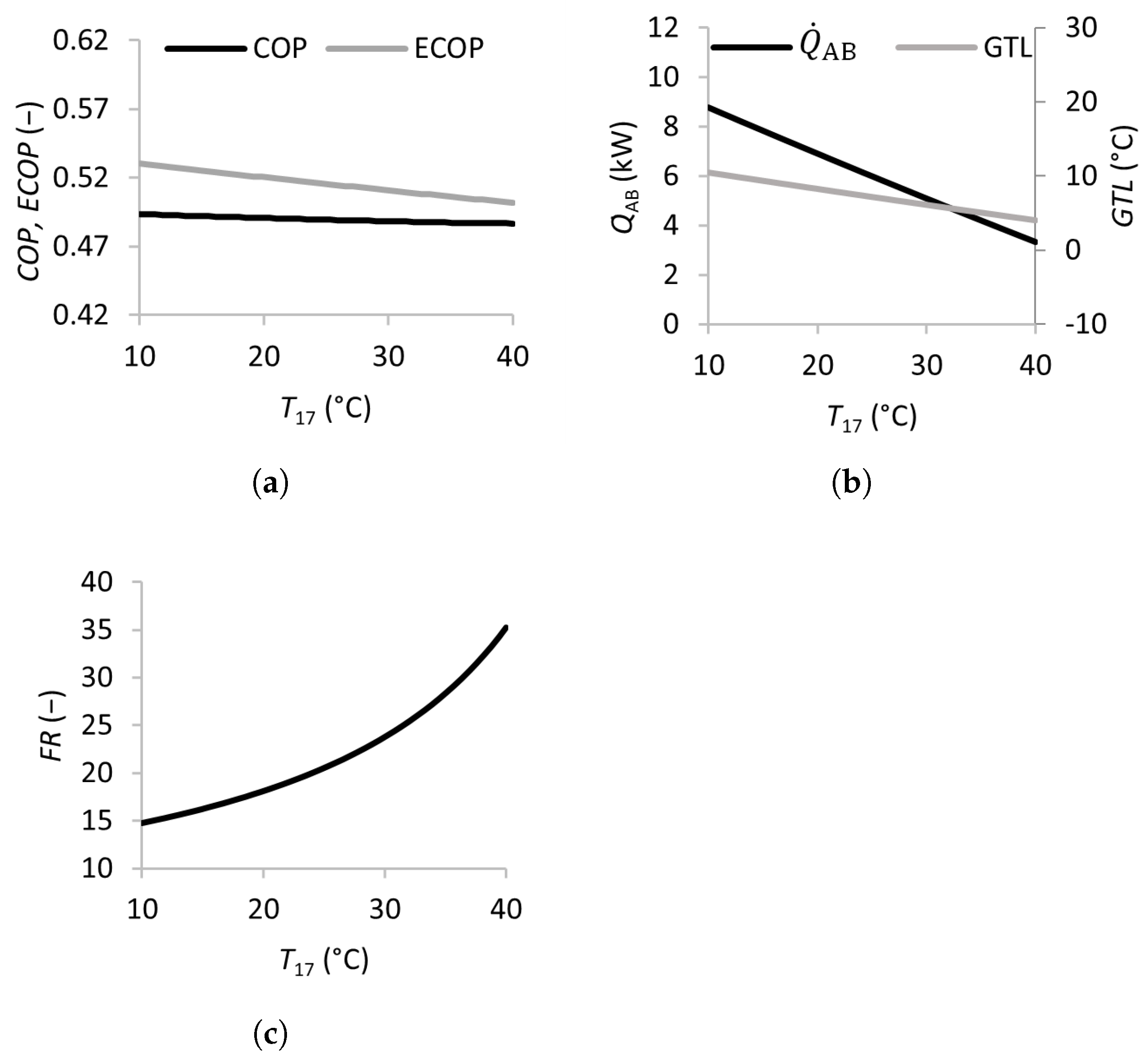
3.2.1. Effects of Inlet Temperatures

The effects of the temperatures of the external feed streams were analyzed in this study—namely, the temperature of the feed stream to be upgraded in the absorber T 11 , the temperature of the waste heat streams entering the generator and evaporator T 13 and T 15 , and that of the cooling stream in the condenser T 17 . The effects of varying these temperatures on the performance of the SSAHT are summarized in Figure 2, Figure 3 and Figure 4.
As shown in Figure 2, increasing the absorber inlet temperature T 11 from 40 to 80 °C leads to a slight decrease in the C O P , while the E C O P increases significantly. The study by Rivera et al. [21] reports decreasing C O P and E C O P values with increasing absorber temperatures in the range of 78 to 92 °C, justified by the increasing irreversibilities. The apparent discrepancy in the trend of the E C O P can be attributed to the different definitions of the E C O P used by Rivera et al. [21]. The G T L increases considerably from −8 to 25 °C, while the absorber heat transfer rate decreases from 10 to 4 kW. This behavior is consistent with the results of Siqueiros and Romero [16], who reported decreasing C O P and absorber heat transfer values with increasing absorber inlet temperatures. The reason is that, as the absorber temperature increases, and the condenser, generator, and evaporator temperatures remain constant, the concentration of the weak solution leaving the absorber x 1 increases at a higher rate than the concentration of the strong solution x 4 . The decreasing weak/strong solution concentration difference results in higher flow ratios and a lower C O P . Increasing T 11 also leads to a moderate increase in the F R from 15 to 32, which implies larger and costlier equipment, but this can be an acceptable tradeoff to obtain a higher-temperature product.
Figure 3 illustrates the effects of the waste heat source temperature in the SSAHT. Waste heat is utilized in both the generator and evaporator and is added to the system through streams 13 and 15 at the corresponding temperatures T 13 and T 15 . Increasing T 13 and T 15 from 40 to 45 °C leads to a sharp increase in the C O P and E C O P , when the F R dramatically decreases from over 150 to approximately 50. This behavior is expected because of the higher heat source temperatures, which increase the energy available for transfer in the absorber Q ˙ AB . Beyond this range, increasing the temperature only modestly improves the C O P and decreases the E C O P and G T L . Nevertheless, increasing T 13 and T 15 is beneficial due to the decreasing F R , as well as the higher associated system pressures (lower vacuum), and these features can make the equipment less expensive and less prone to operational problems such as infiltration.
The effects of the condenser cooling stream temperature T 17 are shown in Figure 4. Increasing T 17 from 10 to 40 °C leads to a slight decrease in the E C O P from 0.53 to 0.50, with the C O P remaining almost constant. The Q ˙ AB and G T L both decrease by approximately 60 %, and the F R more than doubles in value.

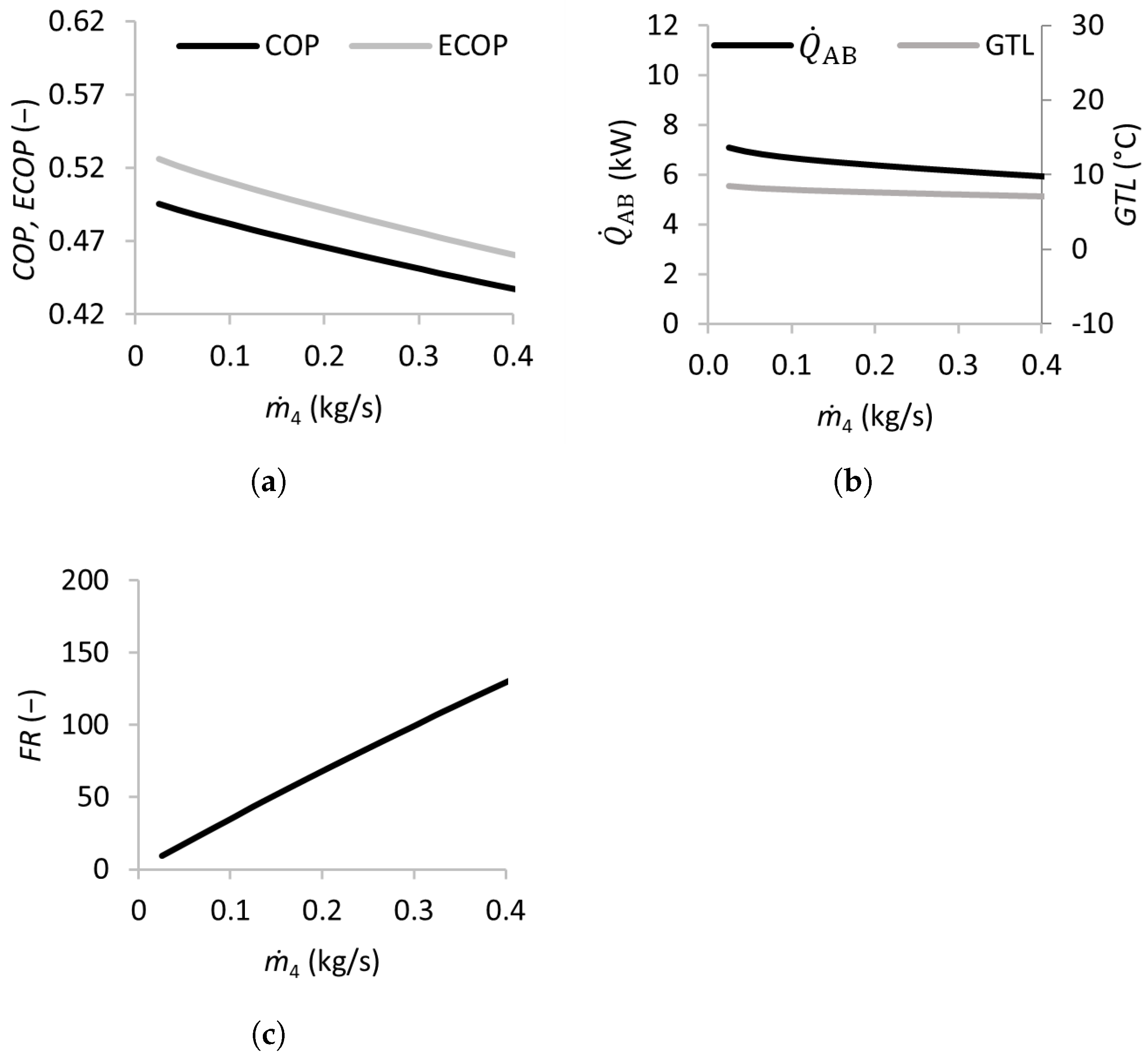
3.2.2. Effects of the Strong Solution Mass Flow Rate

The effect of the strong solution mass flow rate m ˙ 4 was analyzed by varying the flow rate between 0.025 and 0.4 kg/s, and the results are presented in Figure 5. The C O P and E C O P decreased almost linearly when m ˙ 4 increased from 0.025 to 0.4 kg/s. The Q ˙ AB also decreased slightly, while the G T L was almost constant. The flow ratio F R increased almost linearly with m ˙ 4 , surpassing 40 for mass flow rates above 0.1 kg/s. This indicates that flow rates above this threshold are detrimental to the SSAHT’s performance, requiring larger and more expensive equipment (heat exchangers, pumps, etc.).

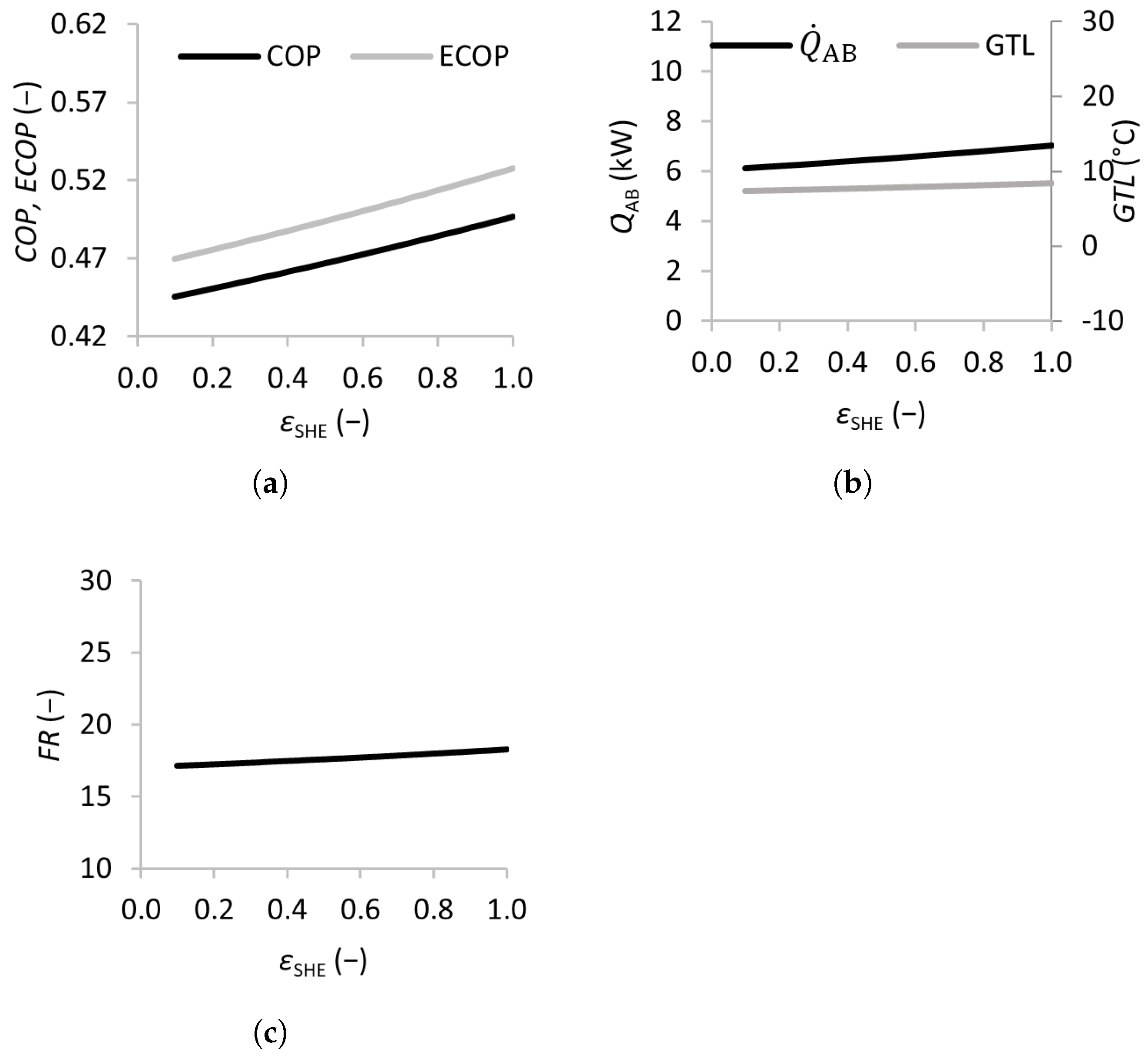
3.2.3. Heat Exchanger Effectiveness

Figure 6 shows the results of varying the solution heat exchanger effectiveness ε SHE from 0 (no solution heat exchanger) to 1 (maximum efficiency). The C O P and E C O P of the SSAHT were found to increase almost linearly with ε SHE , with the C O P increasing from 0.45 to 0.50 and the E C O P from 0.47 to 0.53, which justifies the inclusion of the solution heat exchanger in the SSAHT system.

3.3. Improved SSAHT Results

The sensitivity analysis provided valuable information and revealed possible improvements to the base case (Table 1). Table 2 shows the results obtained by altering some of the input parameters. Specifically, reducing the mass flow rate of the strong solution stream m ˙ 4 and the mass flow rate of the absorber inlet stream m ˙ 11 led to a slight increase in the C O P and E C O P when compared to the base scenario (0.496 vs. 0.491 and 0.596 vs. 0.581, respectively). These minor improvements reflect the low sensitivity of these performance parameters to small temperature variations when lower mass flow rates are employed. Due to the interdependence of the system variables, all variables adjust according to the new equilibrium, and the heat transfer rates Q ˙ are mostly unaffected.
More remarkably, the optimized configuration led to a significant reduction in the F R , which decreased to 9.85, nearly half of the base value. This reduction is directly related to the decrease in the strong solution mass flow rate m ˙ 4 , emphasizing that lower flow rates contribute to more cost-effective equipment selection.
Additionally, the output heat temperature in the optimized version is 76 °C, an increase over the previous value of 68 °C. It should be noted, however, that the heating capacity Q ˙ AB was not improved over the original 6.9 kW; only the product temperature T 12 increased due to the reduced mass flow rate m ˙ 12 . This enhancement in the thermal energy quality, despite its unchanging quantity, is relevant for applications where higher temperatures are critical—for example, pasteurization and other heat treatments. Moreover, operating at a higher temperature and lower mass flow rate can improve the efficiency of the process by reducing the pumping requirements.
Another possible improvement to the base parameters would include using a lower cooling fluid temperature T 17 . However, this may be difficult in practice because it would require the availability of a colder fluid; therefore, this change was not considered.
It is important to point out that the improvements in performance were obtained under ideal modeling assumptions, such as no heat losses to the environment. In practical applications, an increase in the absorber temperature would likely lead to higher heat losses (irreversibilities) in this component, offsetting the small gains in the C O P and E C O P . Moreover, heat losses in the generator can hinder the desorption process, affecting the concentration gradient between the strong and weak solutions, which is critical for the subsequent absorption process, thus affecting the performance of the entire cycle. These considerations are important for heat exchanger design, which should be optimized to minimize heat losses to the environment.
Nonetheless, the optimized parameters and insights provided in this study can be used as a starting point for the design of SSAHT prototypes for low-temperature waste heat recovery.

4. Conclusions

This study used a thermodynamic modeling approach to evaluate the performance of an SSAHT operating with the H2O/LiBr working pair. A sensitivity analysis was performed, focusing on some key input parameters, such as the inlet temperatures, mass flow rates, and effectiveness of the solution heat exchanger.
The sensitivity analysis allowed an improvement in the base model. The temperatures of the external feed streams have a strong impact on all performance parameters. The mass flow rate of the strong solution m ˙ 4 also has a significant effect, particularly in the F R , which reaches values over 30 for m ˙ 4 above 0.1 kg/s. The solution heat exchanger is confirmed to be a key component in SSAHTs, as the C O P and E C O P increase almost linearly with increasing ε SHE .
The SSAHT is theoretically capable of recovering low-temperature waste heat at 60 °C, upgrading it to a more useful temperature level at 76 °C, with a C O P of 0.5. This translates to 50 % of the available thermal energy from the waste stream being used to obtain a higher-temperature output. However, these results do not reflect any heat or power losses to the environment, nor do they consider any practical aspects that can hinder the SSAHT’s performance, such as pressure drops in the heat exchangers, corrosion, or air infiltrations, for example. Further experimental studies are needed to determine the technical and economic feasibility of operating in this lower-temperature range with the H2O/LiBr working pair.

Author Contributions

Conceptualization, investigation, software, M.S.; writing—original draft preparation, M.S.; writing—review and editing, C.P. and J.B.L.M.C.; project administration, J.B.L.M.C. All authors have read and agreed to the published version of the manuscript.

Funding

This work was financially supported by Fundação para a Ciência e Tecnologia (FCT, Portugal), through research scholarships PD/BD/137884/2018 and COVID/BD/152637/2022, as well as Transport Phenomena Research Center (CEFT) base funding (UIDB/00532/2020) and Associate Laboratory in Chemical Engineering (ALiCE) funding (LA/P/0045/2020).

Data Availability Statement

The original contributions presented in this study are included in the article. Further inquiries can be directed to the corresponding author.

Conflicts of Interest

The authors declare no conflicts of interest.

Nomenclature

AArea (m2)
AHTAbsorption heat transformer
cSpecific heat (J/(kg °C))
C O P Coefficient of performance (−)
E C O P Exergetic coefficient (−)
F t Correction factor for Δ T ln (−)
F R Flow ratio (−)
G T L Gross temperature lift (°C)
H2O/LiBrWater/lithium bromide
NH3/H2OAmmonia/water
hSpecific enthalpy (J/kg)
mMass flow rate (kg/s)
PPressure (kPa)
Q ˙ Heat transfer rate (W)
QVapor quality (−)
SSAHTSingle-stage absorption heat transformer
TTemperature (°C)
T 0 Reference temperature (°C)
UOverall heat transfer coefficient (W/(m2 °C))
W ˙ Pump power (W)
xSolution mass concentration (−)
ε Heat exchanger effectiveness (−)
Δ T Temperature difference (°C)
Δ T m Mean temperature difference (°C)
Δ T ln Logarithmic mean temperature difference (°C)
Subscripts
ABAbsorber
COCondenser
EVEvaporator
GEGenerator
iStream number index (1–18)
inInlet
outOutlet
SHESolution heat exchanger

References

  1. Cudok, F.; Giannetti, N.; Ciganda, J.L.C.; Aoyama, J.; Babu, P.; Coronas, A.; Fujii, T.; Inoue, N.; Saito, K.; Yamaguchi, S.; et al. Absorption heat transformer—state-of-the-art of industrial applications. Renew. Sustain. Energy Rev. 2021, 141, 110757. [Google Scholar] [CrossRef]
  2. Parham, K.; Khamooshi, M.; Tematio, D.B.K.; Yari, M.; Atikol, U. Absorption heat transformers—A comprehensive review. Renew. Sustain. Energy Rev. 2014, 34, 430–452. [Google Scholar] [CrossRef]
  3. Huicochea, A.; Siqueiros, J.; Romero, R.J. Portable water purification system integrated to a heat transformer. Desalination 2004, 165, 385–391. [Google Scholar] [CrossRef]
  4. Huicochea, A.; Siqueiros, J. Improved efficiency of energy use of a heat transformer using a water purification system. Desalination 2010, 257, 8–15. [Google Scholar] [CrossRef]
  5. Garone, S.; Toppi, T.; Guerra, M.; Motta, M. A water-ammonia heat transformer to upgrade low-temperature waste heat. Appl. Therm. Eng. 2017, 127, 748–757. [Google Scholar] [CrossRef]
  6. Kurem, E.; Horuz, I. A comparison between ammonia-water and water-lithium bromide solutions in absorption heat transformers. Int. Comm. Heat Mass Transfer 2001, 28, 427–438. [Google Scholar] [CrossRef]
  7. Rivera, W.; Romero, R.J.; Cardoso, M.J.; Aguillón, J.; Best, R. Theoretical and experimental comparison of the performance of a single-stage heat transformer operating with water/lithium bromide and water/Carrol ™. Int. J. Energy Res. 2002, 26, 747–762. [Google Scholar] [CrossRef]
  8. Yin, J.; Shi, L.; Zhu, M.S.; Han, L.Z. Performance analysis of an absorption heat transformer with different working fluid combinations. Appl. Energy 2000, 67, 281–292. [Google Scholar] [CrossRef]
  9. Sözen, A.; Yücesu, H.S. Performance improvement of absorption heat transformer. Renew. Energy 2007, 32, 267–284. [Google Scholar] [CrossRef]
  10. Horuz, I.; Kurt, B. Absorption heat transformers and an industrial application. Renew. Energy 2010, 35, 2175–2181. [Google Scholar] [CrossRef]
  11. Zhang, X.; Hu, D. Performance analysis of the single-stage absorption heat transformer using a new working pair composed of ionic liquid and water. Appl. Therm. Eng. 2012, 37, 129–135. [Google Scholar] [CrossRef]
  12. Herold, K.E.; Radermacher, R.; Klein, S.A. Absorption Chillers and Heat Pumps, 2nd ed.; CRC Press: Boca Raton, FL, USA, 2016; p. 386. [Google Scholar]
  13. López-Pérez, L.A.; Torres-Díaz, T.; Pérez Grajales, S.G.; Flores Prieto, J.J.; Juárez Romero, D.; Hernández Pérez, J.A.; Huicochea, A. Solar Water Heating System with Absorption Heat Transformer for Annual Continuous Water Heating. Processes 2024, 12, 1650. [Google Scholar] [CrossRef]
  14. Rivera, W.; Cardoso, M.J.; Romero, R.J. Single-stage and advanced absorption heat transformers operating with lithium bromide mixtures used to increase solar pond’s temperature. Sol. Energy Mater. Sol. Cells 2001, 70, 321–333. [Google Scholar] [CrossRef]
  15. Ibarra-Bahena, J.; Dehesa-Carrasco, U.; Montiel-González, M.; Romero, R.J.; Venegas-Reyes, E. Feasibility analysis of a hot water solar system coupled to an absorption heat transformer. Appl. Therm. Eng. 2017, 114, 1176–1185. [Google Scholar] [CrossRef]
  16. Siqueiros, J.; Romero, R.J. Increase of COP for heat transformer in water purification systems. Part I-Increasing heat source temperature. Appl. Therm. Eng. 2007, 27, 1043–1053. [Google Scholar] [CrossRef]
  17. ASHRAE. Ashrae ® Handbook-Fundamentals; ASHRAE: Atlanta, GA, USA, 2009; Volume 30329. [Google Scholar]
  18. Çengel, Y.A. Heat Transfer: A Practical Approach, 2nd ed.; Mcgraw-Hill: New York, NY, USA, 2002. [Google Scholar]
  19. Ibarra-Bahena, J.; Romero, R.J.; Velazquez-Avelar, L.; Valdez-Morales, C.V.; Galindo-Luna, Y.R. Experimental thermodynamic evaluation for a single stage heat transformer prototype build with commercial PHEs. Appl. Therm. Eng. 2015, 75, 1262–1270. [Google Scholar] [CrossRef]
  20. Romero, R.J.; Martínez, A.R.; Silva, S.; Cerezo, J.; Rivera, W. Comparison of double stage heat transformer with double absorption heat transformer operating with Carrol—Water for industrial waste heat recovery. Chem. Eng. Trans. 2011, 25, 129–134. [Google Scholar]
  21. Rivera, W.; Martínez, H.; Cerezo, J.; Romero, R.J.; Cardoso, M.J. Exergy analysis of an experimental single-stage heat transformer operating with single water/lithium bromide and using additives (1-octanol and 2-ethyl-1-hexanol). Appl. Therm. Eng. 2011, 31, 3525–3532. [Google Scholar] [CrossRef]
Figure 1. Schematic representation of the single-stage absorption heat transformer (SSAHT), where the numbers identify the streams used in the modeling equations.
Processes 13 01001 g001
Figure 2. Effects of the inlet temperatures of the absorber on the coefficient of performance (a), absorber heat transfer rate and gross temperature lift (b), and flow ratio (c).
Processes 13 01001 g002
Figure 3. Effects of the waste heat temperature (inlet temperatures of the generator and evaporator) on the coefficient of performance (a), absorber heat transfer rate, gross temperature lift (b), and flow ratio (c).
Processes 13 01001 g003
Figure 4. Effects of the inlet temperature of the condenser on the coefficient of performance (a), absorber heat transfer rate and gross temperature lift (b), and flow ratio (c).
Processes 13 01001 g004
Figure 5. Effects of the mass flow rate of the strong solution on the coefficient of performance (a), absorber heat transfer rate and gross temperature lift (b), and flow ratio (c).
Processes 13 01001 g005
Figure 6. Effects of the solution heat exchanger effectiveness on the coefficient of performance (a), absorber heat transfer rate and gross temperature lift (b), and flow ratio (c).
Processes 13 01001 g006
Table 1. Operating conditions obtained for the base model, with the state points corresponding to the stream numbers from Figure 1. Values in bold correspond to the simulation input parameters.
State Point h i (kJ/kg) m ˙ i (kg/s) P i (kPa) Q i (−) T i (°C) x i (kg/kg)
1120.70.0534.8400.00650.740.4574
2120.70.05312.187 56.820.4574
3150.50.05312.1870.00069.570.4574
4146.40.05012.187 68.020.4841
5114.80.05012.187 54.030.4841
6114.80.0504.8400.00054.030.4841
72594.80.0034.840 50.740.0000
8135.30.0034.8400.00032.300.0000
9135.30.00312.187 32.300.0000
102590.80.00312.1871.00049.730.0000
11 0.200 60.00
12 68.26
13 0.200 60.00
14 51.73
15 0.200 60.00
16 51.44
17 0.200 20.00
18 28.57
COP (−)0.491 Q ˙ AB (kW)6.9
ECOP (−)0.581 Q ˙ GE (kW)6.9
GTL (°C)19.84 Q ˙ CO (kW)7.2
FR (−)18.14 Q ˙ EV (kW)7.2
W ˙ R / W ˙ S (W)0.022/0.25 Q ˙ SHE (kW)1.6
Table 2. Operating conditions obtained using improved input parameters. The state points correspond to the stream numbers from Figure 1 and the values in bold to the simulation input parameters.
State Point h i (kJ/kg) m ˙ i (kg/s) P i (kPa) Q i (−) T i (°C) x i (kg/kg)
1126.80.0284.2430.01048.960.4614
2126.80.02812.363 59.500.4614
3152.30.02812.3630.00070.430.4614
4150.40.02512.363 68.980.5135
5122.10.02512.363 55.950.5135
6122.10.0254.2430.00055.950.5135
72591.60.0034.243 48.960.0000
8125.70.0034.2430.00029.980.0000
9125.70.00312.363 29.990.0000
102591.30.00312.3631.00050.020.0000
11 0.100 60.00
12 76.35
13 0.200 60.00
14 51.83
15 0.200 60.00
16 51.68
17 0.200 20.00
18 28.32
COP (−)0.496 Q ˙ AB (kW)6.9
ECOP (−)0.596 Q ˙ GE (kW)6.9
GTL (°C)20.41 Q ˙ CO (kW)7.0
FR (−)9.851 Q ˙ EV (kW)7.0
W ˙ R / W ˙ S (W)0.023/0.13 Q ˙ SHE (kW)0.7
Disclaimer/Publisher’s Note: The statements, opinions and data contained in all publications are solely those of the individual author(s) and contributor(s) and not of MDPI and/or the editor(s). MDPI and/or the editor(s) disclaim responsibility for any injury to people or property resulting from any ideas, methods, instructions or products referred to in the content.

