Abstract
Deep coalbed methane (CBM) reservoirs hold substantial resource potential and play a crucial role in China’s unconventional natural gas development. However, the vertical propagation behavior of hydraulic fractures in deep CBM formations remains inadequately understood, posing challenges for optimizing fracturing parameters to control fracture height growth and enhance fracture development within the coal seam. To address this, this study establishes numerical simulation models to investigate hydraulic fracture propagation in directional wells, incorporating three typical lithological combinations representative of deep CBM reservoirs. Through these models, the influence mechanisms of bedding density, stress ratio, rock friction coefficient, and fracturing parameters on vertical fracture propagation and post-fracture productivity were systematically analyzed. The results reveal that the fracture propagation characteristics vary significantly with lithological combinations. Initially, hydraulic fractures penetrated adjacent formations near the wellbore while simultaneously generating branched fractures, leading to the formation of a complex fracture network. As propagation continues, branch fractures exhibited reduced width compared to the primary fracture. Well-developed bedding planes in the roof or floor, combined with lower stress ratios and friction coefficients, effectively constrained vertical fracture growth. Furthermore, optimizing fracturing fluid volume, reducing injection rate, and lowering proppant concentration promoted fracture development within the coal seam, thereby enhancing post-fracture well productivity. These findings provide a theoretical foundation for the optimization of hydraulic fracturing strategies in deep CBM reservoirs, contributing to more effective reservoir stimulation and resource recovery.
1. Introduction
Unlike shallow CBM resources, deep CBM reservoirs are typically located at depths greater than 1500 m. Shallow CBM reservoirs are characterized by high adsorbed gas content and low free gas content [1]. In contrast, deep CBM reservoirs can have free gas content as high as 35%. These reservoirs are distinguished by greater burial depths, well-developed reservoir cleats, natural fractures, and rocks with high brittleness [2]. Hydraulic fracturing is employed to create extensive fracture networks in deep CBM reservoirs, thereby facilitating the flow of free gas. As a result, hydraulic fracturing has become the primary technique for the economically viable development of deep CBM reservoirs [3,4].
Current advancements in laboratory-based true triaxial fracturing experiments have provided more systematic theoretical guidance for the study of dynamic fracture propagation mechanisms in coalbed methane reservoirs, particularly focusing on the extension characteristics of vertical through-layer fractures [5,6,7]. These experiments are designed to simulate realistic in situ stress conditions and fracture behavior under various pressure and stress states. Key findings indicate that fractures in coalbed reservoirs tend to propagate vertically along weak planes, with the potential to propagate through multiple layers, leading to complex fracture networks [8,9]. Researchers have developed novel experimental setups to simulate these conditions, thereby improving the understanding of factors influencing vertical fracture propagation, including rock heterogeneity, in situ stress variations, and fracturing fluid properties [5,10,11]. Despite the progress, challenges remain in accurately predicting the full-scale behavior of fractures under actual field conditions, particularly in terms of fracture height control and the prevention of unwanted vertical fracture growth.
Numerical simulation methods, including the discrete element method (DEM), finite element method (FEM), and boundary element method (BEM), serve as essential tools for investigating hydraulic fracture propagation in CBM reservoirs [12,13,14,15]. DEM is particularly effective in capturing fracture initiation and propagation by explicitly representing rock discontinuities, making it well-suited for modeling the complex fracture networks observed in coal seams. However, its high computational cost and difficulty in accurately simulating fluid flow within fractures limit its applicability in large-scale hydraulic fracturing simulations [16,17,18,19]. FEM, widely used for simulating fracture mechanics in heterogeneous formations, provides detailed stress distribution analysis and fracture propagation patterns. Despite its robustness, FEM struggles to efficiently model fracture branching and complex fracture networks due to mesh dependency and high computational demands [20,21,22,23]. BEM, in contrast, offers computational efficiency and is well-suited for simulating fracture growth in infinite or semi-infinite domains without requiring a volumetric mesh. Nevertheless, its reliance on predefined fracture geometries and difficulty in handling multiple interacting fractures constrain its applicability in CBM fracturing studies [24,25,26]. Although these numerical approaches have significantly advanced the understanding of hydraulic fracture propagation in coal seams, their ability to accurately simulate vertical fracture propagation across layered formations remains limited [27,28]. The complexity arising from varying lithological combinations, stress contrasts, and bedding interfaces in deep CBM reservoirs poses challenges that current models struggle to address. Furthermore, most existing studies primarily focus on fracture propagation itself, with limited efforts to integrate the simulated fracture morphology into production models. As a result, the impact of fracture network geometry on post-fracture well productivity remains insufficiently understood. The lack of a coupled simulation framework that links fracture propagation with production performance limits the ability to accurately evaluate and optimize hydraulic fracturing parameters. Integrating fracture propagation models with post-fracture production simulations would enhance the predictive accuracy of these numerical methods, providing a more comprehensive basis for optimizing hydraulic fracturing strategies in deep CBM reservoirs.
The optimization of hydraulic fracturing parameters is crucial for enhancing the productivity and efficiency of CBM reservoirs. Key parameters, including injection pressure, fluid type, proppant concentration, and fracture spacing, play a significant role in determining the success of a fracturing operation [29]. To maximize fracture propagation extent while minimizing reservoir damage risks, a substantial number of scholars have conducted comprehensive studies on the optimization of these parameters [30]. Research has shown that careful selection of fracturing parameters can significantly affect fracture geometry, conductivity, and long-term production rates. Moreover, optimizing these parameters is essential for reducing operational costs and environmental impact [31,32,33]. While considerable progress has been made in understanding the influence of individual parameters on fracture behavior, the challenge remains in integrating multiple parameters to develop a comprehensive optimization strategy. This study aims to address this gap by proposing a systematic approach to the optimization of hydraulic fracturing parameters for CBM reservoirs, with a focus on improving fracture control and enhancing well productivity.
In this study, we first developed numerical simulation models for hydraulic fracture propagation in directional wells, considering three typical lithology combinations in deep CBM reservoirs. Using these models, we investigated the influence of bedding density, rock friction coefficient, vertical stress, and the ratio of horizontal minimum principal stress to vertical stress on the vertical propagation of hydraulic fractures through the roof and floor. We evaluated how fracturing parameters influence cross-layer fracture propagation and adjusted them for optimal performance. Finally, we compared the fracture network morphology and post-fracture productivity of the coal seam section before and after the optimization of fracturing parameters. Our research provides a solid theoretical foundation for hydraulic fracturing design in deep CBM reservoirs.
2. Numerical Model Development
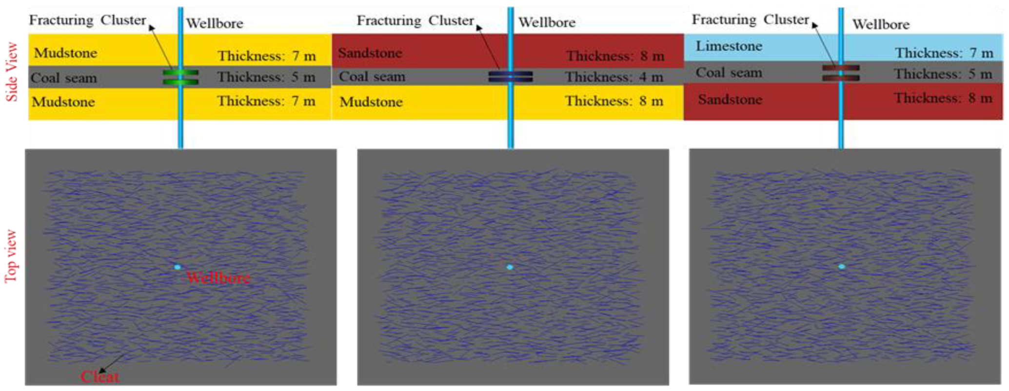
The deep CBM reservoirs in the Ordos Basin of China are rich in natural gas reserves and represent a critical resource for the future development of unconventional oil and gas. Unlike shallow CBM resources, deep CBM reservoirs are typically located at depths greater than 2000 m, characterized by very low reservoir permeability and well-developed cleats and natural fractures. Deep CBM reservoirs rely on hydraulic fracturing technology to connect cleats and natural fractures, enabling economically viable extraction. The primary technical challenge in fracturing coalbed reservoirs is how to use hydraulic fracturing to create large-scale fracture networks within the coal seam, thereby providing effective pathways for natural gas flow. Since the coal seam section is often relatively thin, it is crucial to control the vertical propagation height of hydraulic fractures to facilitate greater lateral fracture extension. This study investigates the vertical propagation mechanisms of hydraulic fractures under vertically heterogeneous lithological assemblages, based on the No. 8 CBM reservoir in a specific block of the Ordos Basin. Figure 1 illustrates the numerical simulation models for directional well hydraulic fracturing, developed using the Kinetix fracturing module in Petrel software (version 2022), for three typical lithology combinations.

Figure 1.
Numerical simulation model of hydraulic fracture propagation in deep coalbed methane reservoirs with different lithology combinations.
The Kinetix fracturing module in Petrel (version 2022) is based on linear elastic fracture mechanics (LEFM), assuming planar fractures governed by stress intensity and rock toughness. It employs pseudo-3D or 2D models, with fluid flow following Darcy’s or non-Darcy laws. The initial stress field is considered uniform, with simplified fluid-solid coupling to account for rock deformation and fracture closure. Proppant transport is modeled based on gravity settling and carrier fluid dynamics, influencing post-fracture conductivity. The rock properties of each layer are assumed to be homogeneous and the distribution of cleats in the coal seam is random. These assumptions provide a practical framework for optimizing hydraulic fracturing in deep coalbed methane reservoirs.
The roof and floor of the coal seam section are typically composed of sandstone, mudstone, and limestone (as shown in the vertical profile of the model in Figure 1). The thicknesses of each layer are statistically derived from inversion results of extensive field well logging data. Well log interpretation and core sampling data indicate that sandstone and limestone are dense and hard, typically not exhibiting natural fractures, while mudstone may have well-developed bedding, which can influence the vertical propagation of hydraulic fractures. Additionally, due to the well-developed cleating in the coal rock reservoir, a certain number of fractures were randomly generated within the coal seam section, as shown in the horizontal profile of the model in Figure 1. The specific parameters of the numerical model are presented in Table 1, which includes the initial mechanical and physical properties for each layer. The model input parameters are statistical results obtained by interpreting field logging data in combination with the experimental data of Wang et al. [34]. In Table 1, SV represents the vertical principal stress, SH represents the maximum horizontal principal stress, and Sh represents the minimum horizontal principal stress.

Table 1.
Numerical model parameters.
The systematic operational framework for modeling hydraulic fracture dynamic extension through Schlumberger’s Petrel (version 2022) platform (specifically the Kinetix geomechanical toolkit) encompasses the following procedural stages: (1) Data Preparation: Integrate regional petrophysical properties, geomechanical parameters, and natural fracture data to build a 3D geological model. (2) Wellbore Modeling: Import well trajectories and completion data, configuring casing-perforation schemes. (3) Fracturing Design: Configure fluid injection parameters (rate/proppant concentration/pressure) according to Appendix A–Table A1. (4) Fracture Simulation: Execute 3D dynamic propagation modeling, analyzing fracture geometry and stress interference effects. (5) Productivity Forecasting: Establish production constraints post-meshing, simulating post-fracturing output dynamics.
3. Numerical Simulation Results
3.1. Discussion of Simulation Results for Combination 1
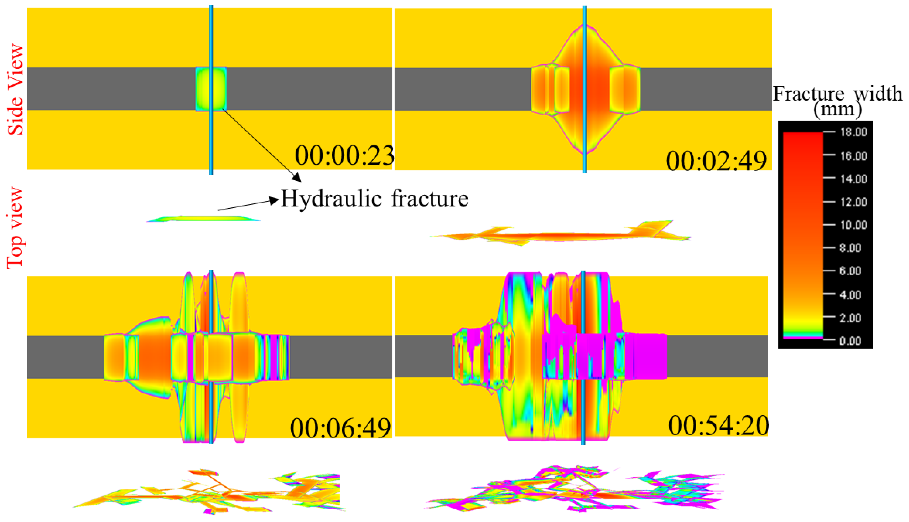
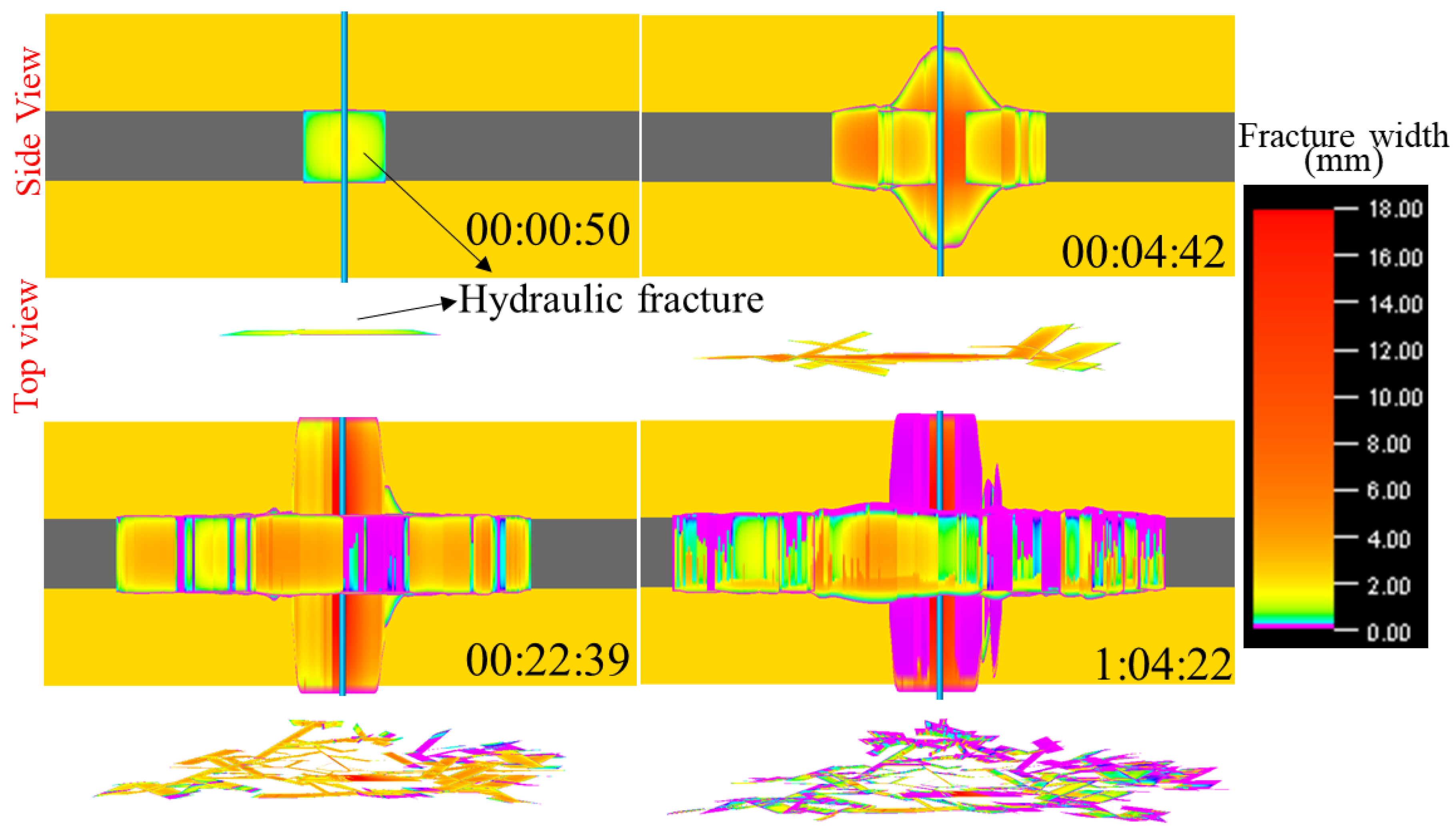
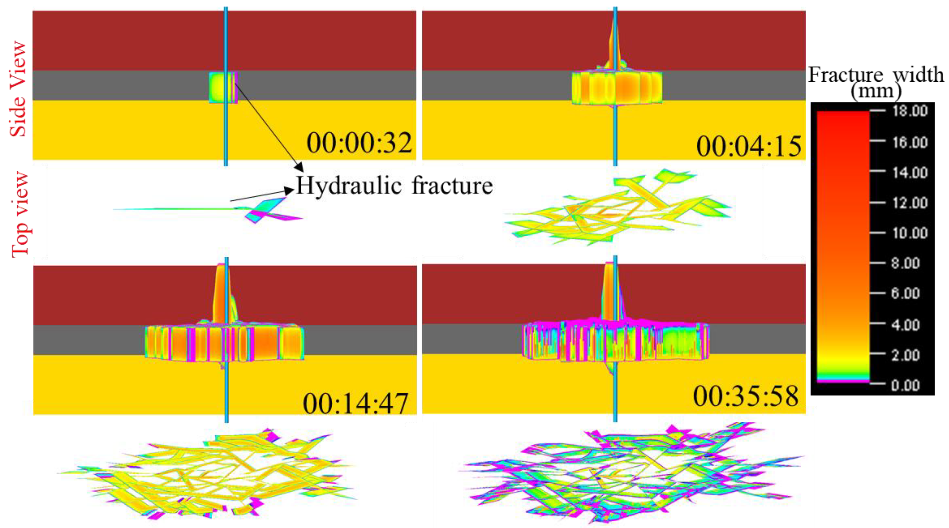
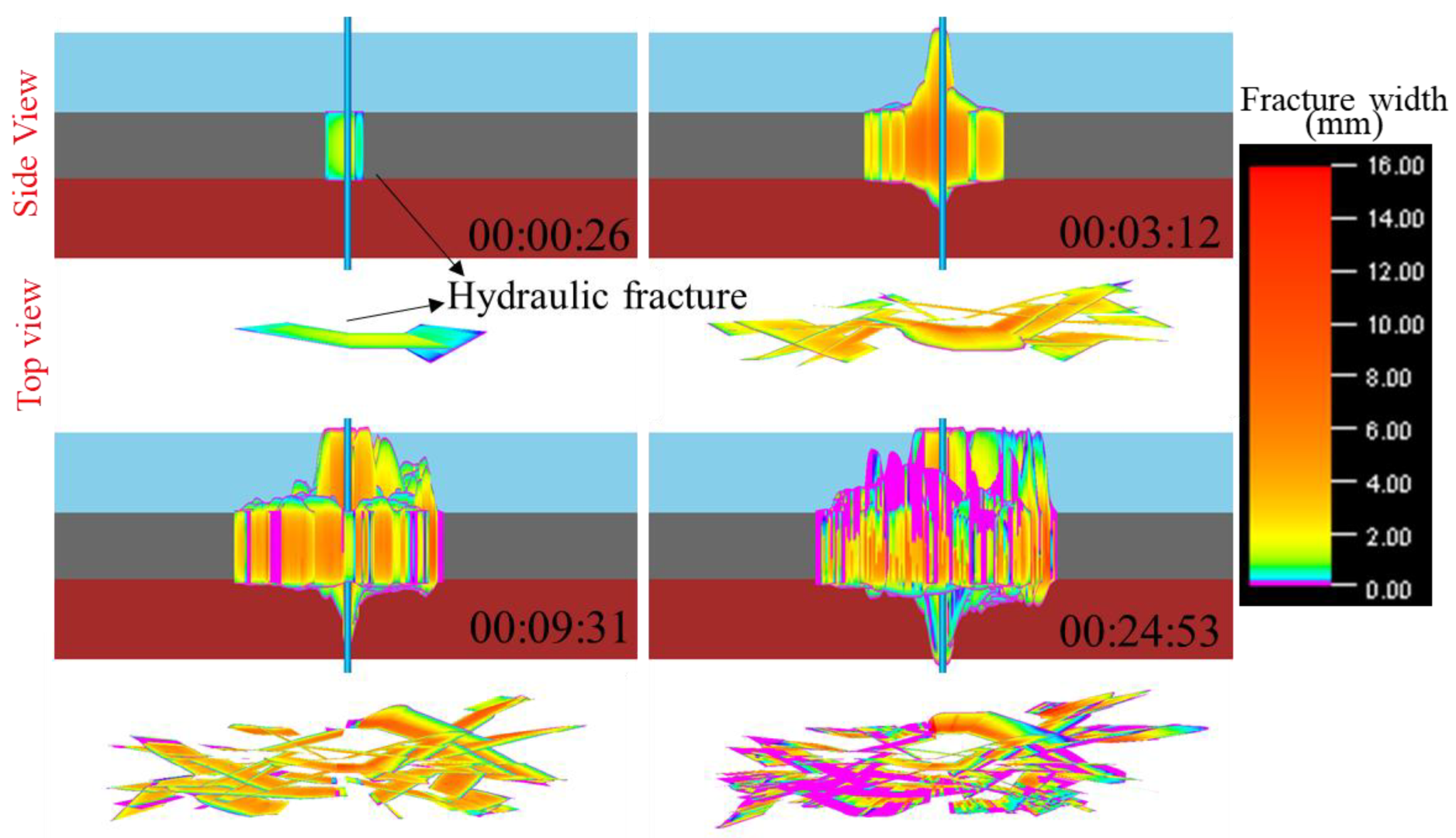
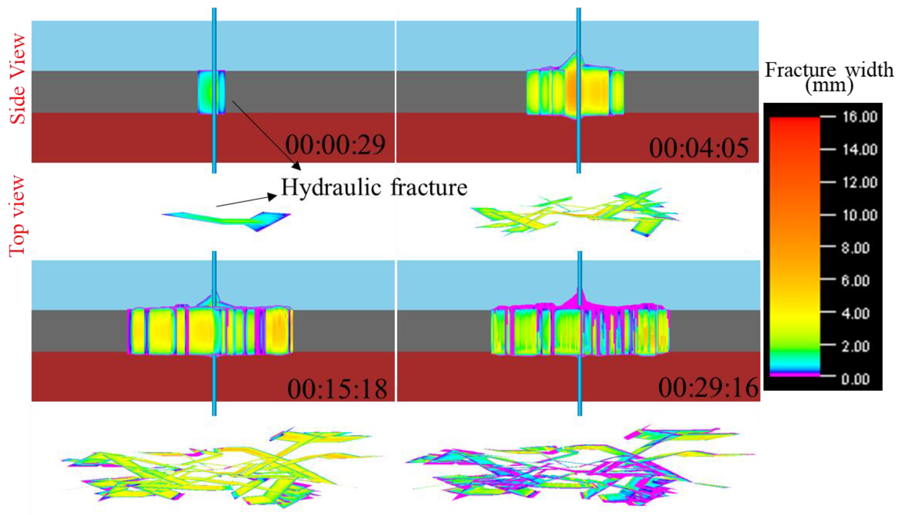
Employing the geomechanical simulation framework developed in Section 2, this study initiates its investigation with an in-depth examination of hydraulic fracture dynamic propagation characteristics under Combination 1 lithological constraints. Figure 2 illustrates the variation in the longitudinal propagation pattern of hydraulic fractures for Combination 1 over time steps, under the original injection schedule used in the field (as shown in Appendix A–Table A1). As shown in Figure 2, initially, hydraulic fractures initiate from the fracturing cluster, with no penetration of the caprock shale or floor shale in the vertical direction. As fracturing fluid is injected, at 2 min and 49 s, the primary fractures near the wellbore begin to propagate through both the caprock and floor shale, with secondary fractures forming along pre-existing fracture planes. Due to the relatively low fracture energy, these secondary fractures do not extend into the caprock or floor shale. By 6 min and 49 s, both the primary and secondary fractures near the wellbore have penetrated the caprock and floor shale, with the secondary fractures continuing to propagate, triggering additional fracture development. At the end of the pump schedule, both the primary fractures and a large number of secondary fractures around the wellbore have penetrated the caprock and floor shale. Compared to the secondary fractures, the primary fractures exhibit larger fracture widths after penetrating the caprock and floor shale. Due to substantial vertical propagation through the layers, the lateral extent of the hydraulic fractures remains relatively limited, and the controlled volume of the fracture network is restricted. A large number of secondary fractures, with fracture widths approaching 0.01 mm, are unable to allow proppant to enter, and therefore become ineffective fractures.

Figure 2.
Spatiotemporal evolution characteristics of hydraulically induced fracture networks along vertical orientation under Combination 1 (Original pump schedule in the field).
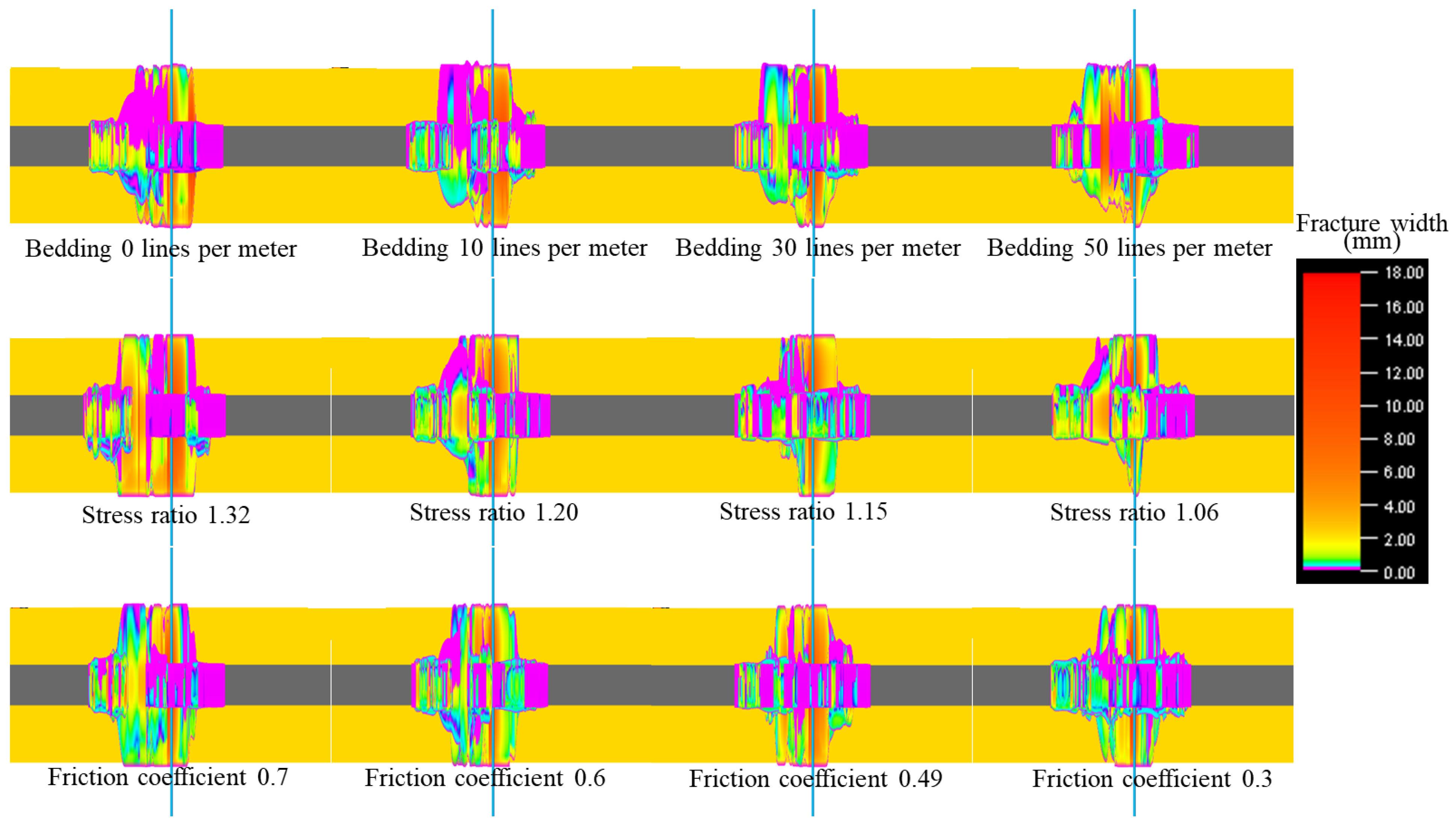
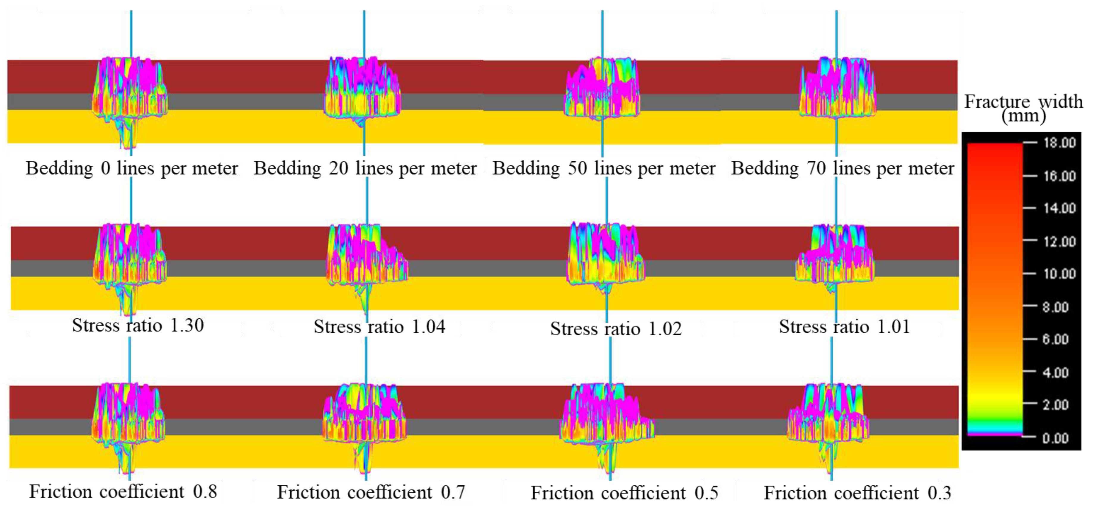
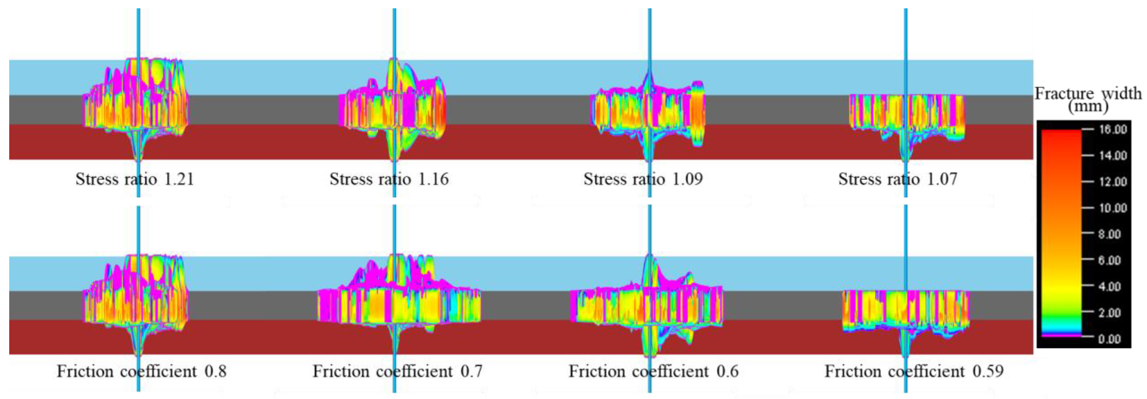
Reservoir heterogeneity often results in variations in mechanical properties, petrophysical parameters, and in situ stresses of the caprock and floor shale. Based on this, we simulated and analyzed the effects of bedding density, stress ratio (SV/Sh), and the interfacial frictional constraints between caprock and floor shale strata in governing the vertical propagation dynamics of hydraulic fracturing networks. The numerical results depicted in Figure 3 reveals that when the layer density of the cap rock mudstone is low, the vertical penetration of hydraulic fractures is significant. Increased bedding-plane density within caprock mudstone strata exhibits a progressive reduction in hydraulic fracture penetration capacity through such lithological units. When the layer density reaches 30 layers/m, only the hydraulic fractures near the wellbore propagate vertically through the cap rock mudstone. At a layer density of 50 layers/m, hydraulic fractures essentially do not penetrate the cap rock mudstone. The denser the layer distribution in the mudstone, the more effectively it prevents the vertical penetration of hydraulic fractures. When the vertical stress SV to minimum horizontal principal stress Sh ratio is large, the vertical penetration of hydraulic fractures through the cap rock mudstone is more significant. As the stress ratio decreases, the vertical penetration of hydraulic fractures through the cap rock mudstone gradually weakens. In formations where the minimum horizontal principal stress is relatively large and close to the vertical principal stress, hydraulic fractures are less likely to propagate through the cap rock mudstone. As the rock friction coefficient decreases, the vertical penetration of hydraulic fractures through the cap rock mudstone gradually weakens. Mudstone with a friction coefficient lower than 0.49 can effectively prevent the vertical penetration of hydraulic fractures through the cap rock mudstone. As shown in Figure 4, with the increase in layer density of the bottom rock mudstone, the hydraulic fracture through-layer through the bottom rock mudstone gradually weakens. Compared to the cap rock mudstone, the increase in layer density of the bottom rock mudstone has a more limited effect in restricting hydraulic fracture through-layer. A decrease in the stress ratio can also limit the vertical penetration of hydraulic fractures through the bottom rock mudstone. However, unlike the cap rock mudstone, the reduction in the friction coefficient of the bottom rock mudstone has a limited effect in restricting fracture through-layer through the bottom rock.
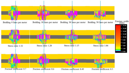
Figure 3.
Effects of different parameters of cap rock mudstone on the vertical propagation of hydraulic fractures in Combination 1.

Figure 4.
Effects of different parameters of bottom rock mudstone on the vertical propagation of hydraulic fractures in Combination 1.
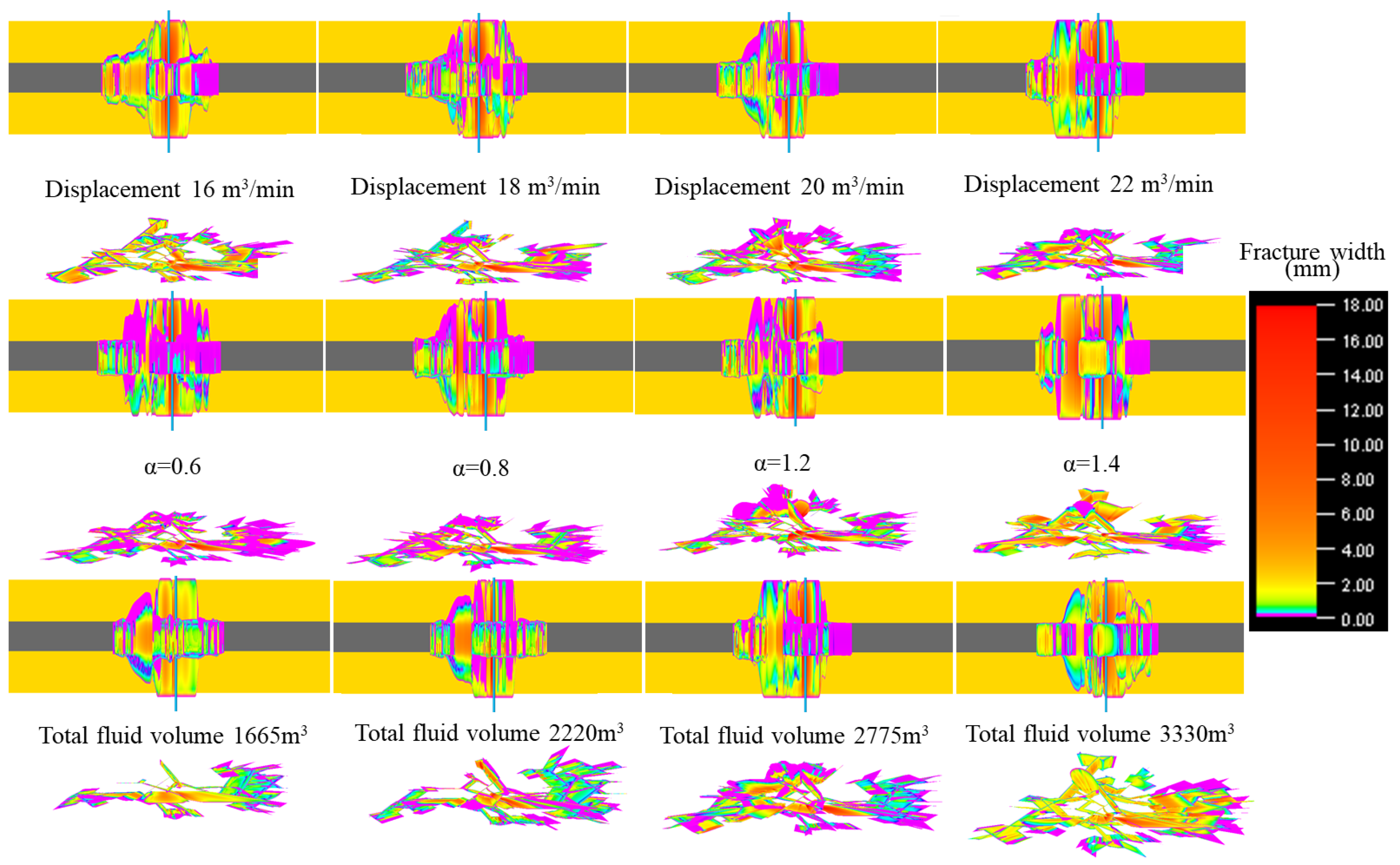
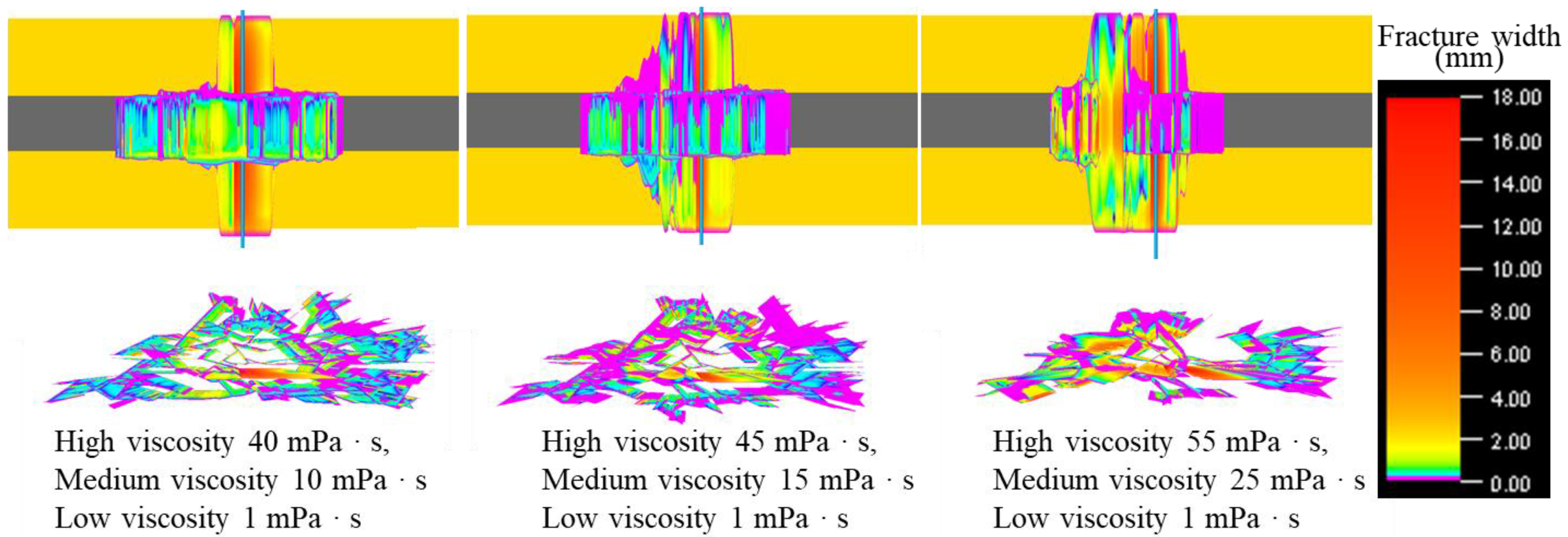
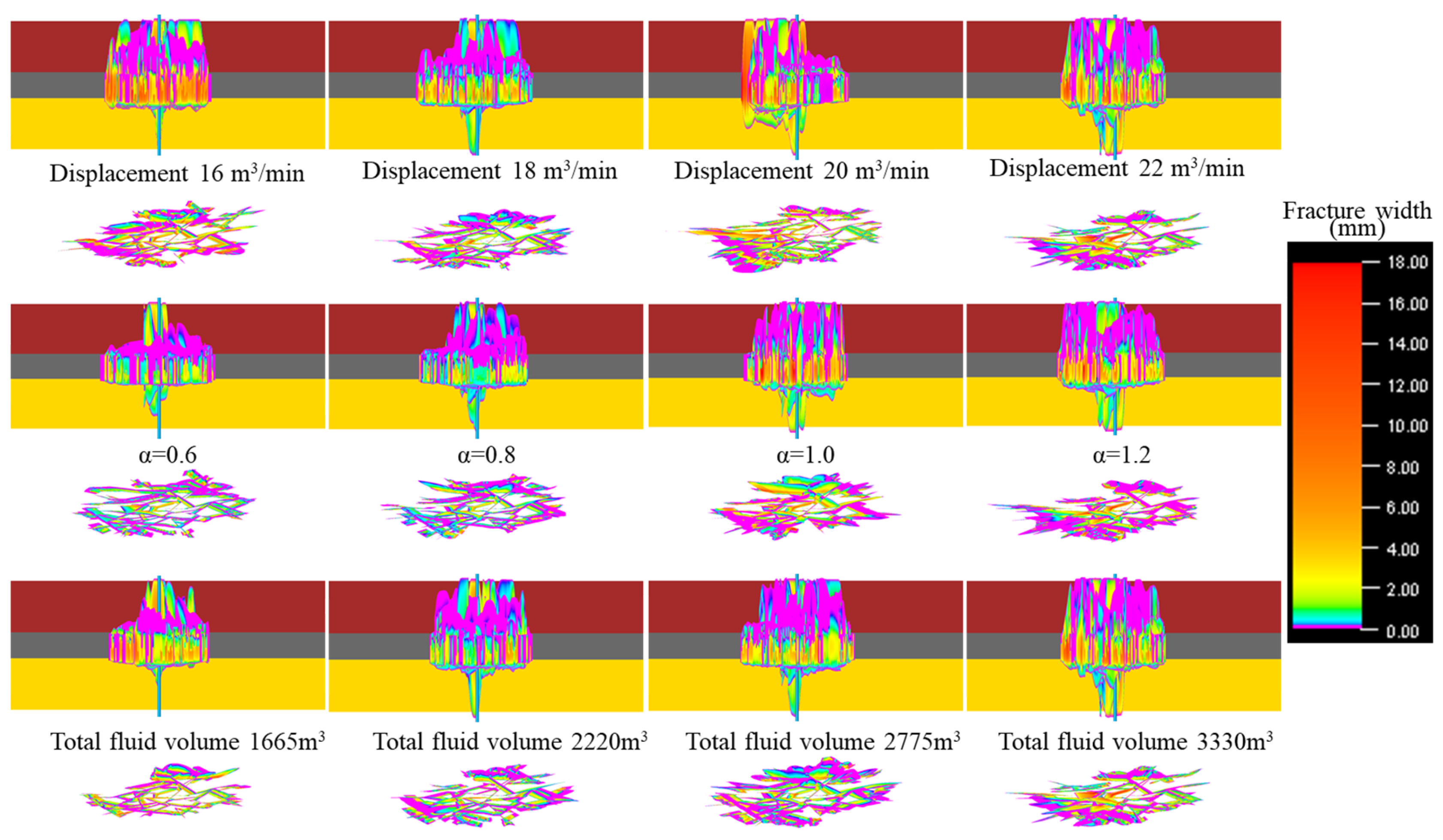
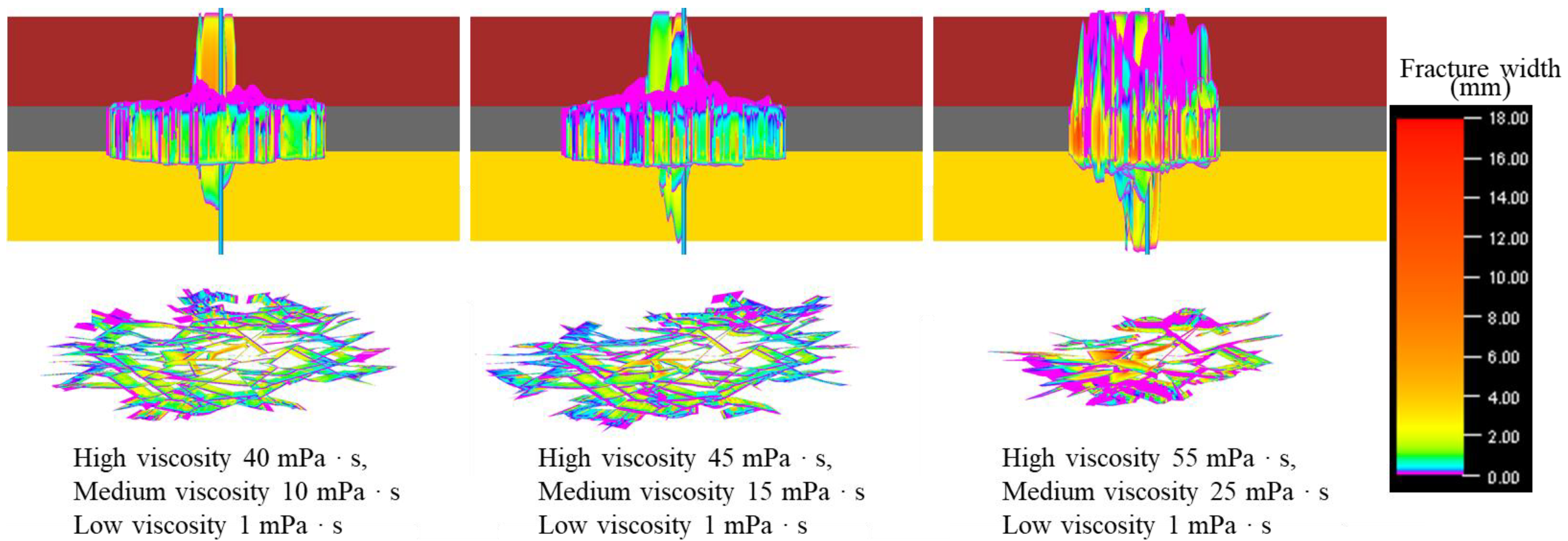
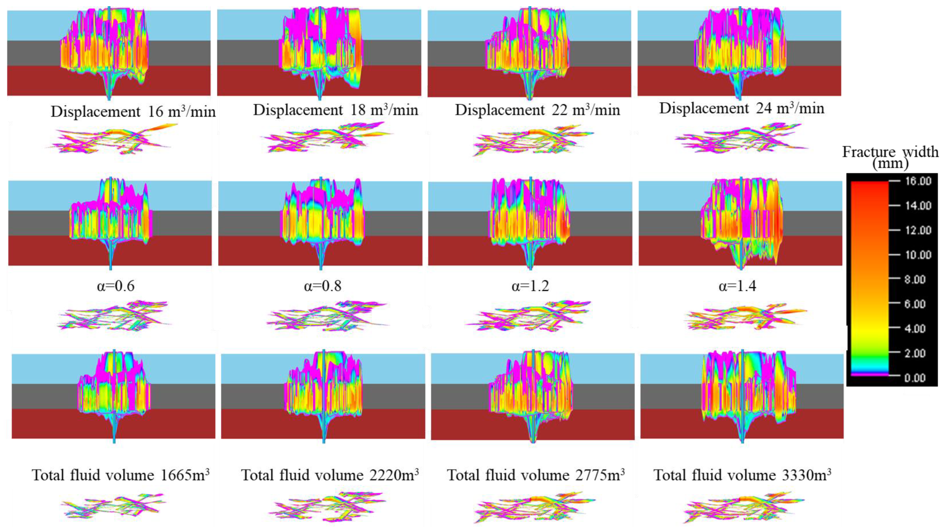
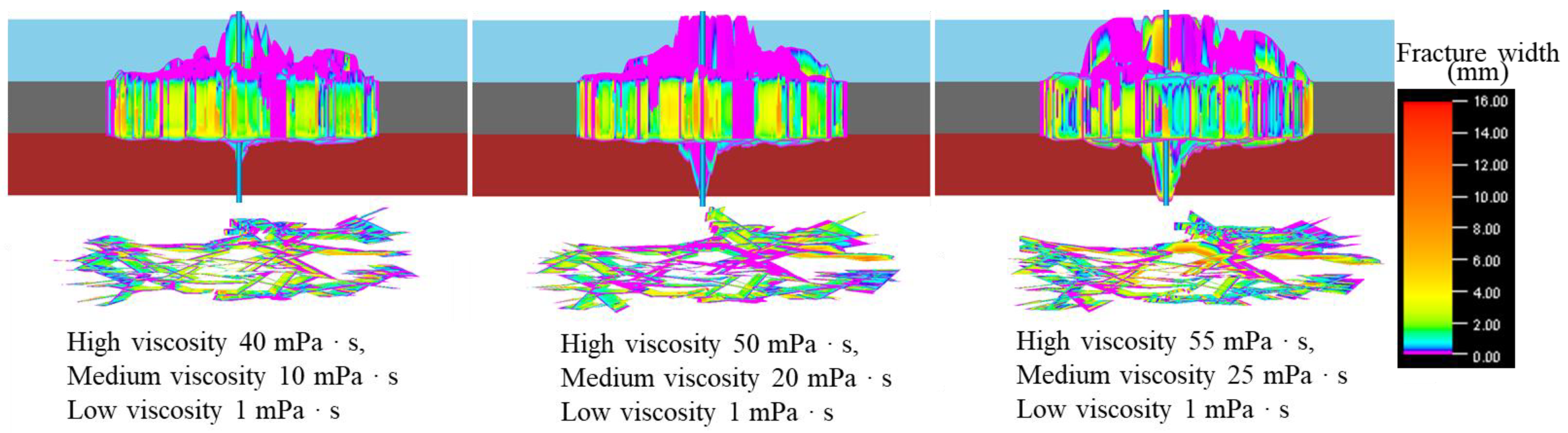
The results in Figure 2 have already shown that under the original pump schedule, the vertical penetration of hydraulic fractures in Combination 1 is quite severe, and the fracturing scale is limited. Therefore, we analyzed the effects of different fracturing parameters and fluid systems on the fracture extension morphology in Combination 1, as shown in Figure 5 and Figure 6. Here, α represents the ratio of the actual sand concentration in the pump schedule to the original sand concentration in Appendix A–Table A1. As shown in Figure 5, declining fracturing fluid injection rates trigger progressive energy dissipation within hydraulic fracture systems, which fundamentally governs the vertically constrained propagation characteristics of fractures adjacent to wellbores. Reducing the injection rate in the coal seam section effectively mitigates vertical fracture propagation. As the injection rate decreases, the fracture width of the secondary fractures initiated around the main fracture in the coal seam section significantly increases, which facilitates proppant entry into the secondary fractures. Additionally, as shown in Figure 5, with the decrease in proppant concentration, the fracture width after vertical propagation significantly reduces. Proppant cannot enter fractures with smaller widths, leading to the closure of fractures that have vertically propagated through the layers after fracturing. Therefore, reducing the proppant concentration can effectively mitigate the impact of vertical fracture propagation. As the total fracturing fluid volume decreases, vertical fracture propagation around the wellbore remains significant, while the fracture propagation phenomenon gradually weakens further from the wellbore. However, from the fracture morphology plan view, it can be observed that a substantial reduction in the total fracturing fluid volume significantly impacts the complexity of the fracture network, reducing the fracturing scale. Therefore, the optimization of fracturing fluid volume proves critical in governing vertical fracture propagation dynamics. As shown in Figure 6, with the decrease in the viscosity of the fracturing fluid system, vertical fracture propagation is significantly suppressed. The number of branch fractures surrounding the main fracture exhibits significant augmentation under the low-viscosity fracturing fluid system. For the Combination 1 reservoir, selecting a low-viscosity fracturing fluid system can effectively limit the vertical propagation of fractures through the caprock and floor shale, thereby increasing the scale of hydraulic fractures in the coal seam section.
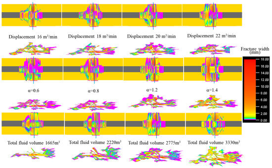
Figure 5.
Effects of different fracturing parameters on the propagation morphology of hydraulic fractures in Combination 1.

Figure 6.
Hydraulic fracture growth patterns modulated by fracturing fluid formulations within Combination 1.
Through the single-factor analysis presented in Figure 5 and Figure 6, we ultimately determined the optimal fracturing parameters as follows: an injection rate of 16 m3/min, a proppant concentration of 0.6 times the original proppant concentration, a fracturing fluid system exhibiting viscosity values spanning from 1 mPa·s to 40 mPa·s, coupled with a total injected volume of 2775 m3. Hydraulic fracture propagation simulations were then conducted using these optimized fracturing parameters, and the results are shown in Figure 7. Comparing Figure 2 and Figure 7, it can be observed that after the optimization of fracturing parameters, although hydraulic fractures still initiate near the wellbore and propagate vertically, the time for vertical propagation is delayed, and the fracture width after vertical propagation is reduced. With the injection of fracturing fluid, the phenomenon of vertical propagation of branch fractures is significantly suppressed, with only severe vertical propagation of fractures near the wellbore, while vertical propagation of secondary fractures is greatly reduced. After fracturing is completed, the fracture width of the fractures that have propagated vertically near the wellbore is relatively small, approaching a closed state. Overall, the optimized fracturing parameters can effectively limit the vertical growth of fractures within the caprock and floor shale while enhancing the complexity of the fracture network.

Figure 7.
Vertical growth patterns of hydraulic fractures at various time steps in Combination 1 (After optimizing the pump schedule).
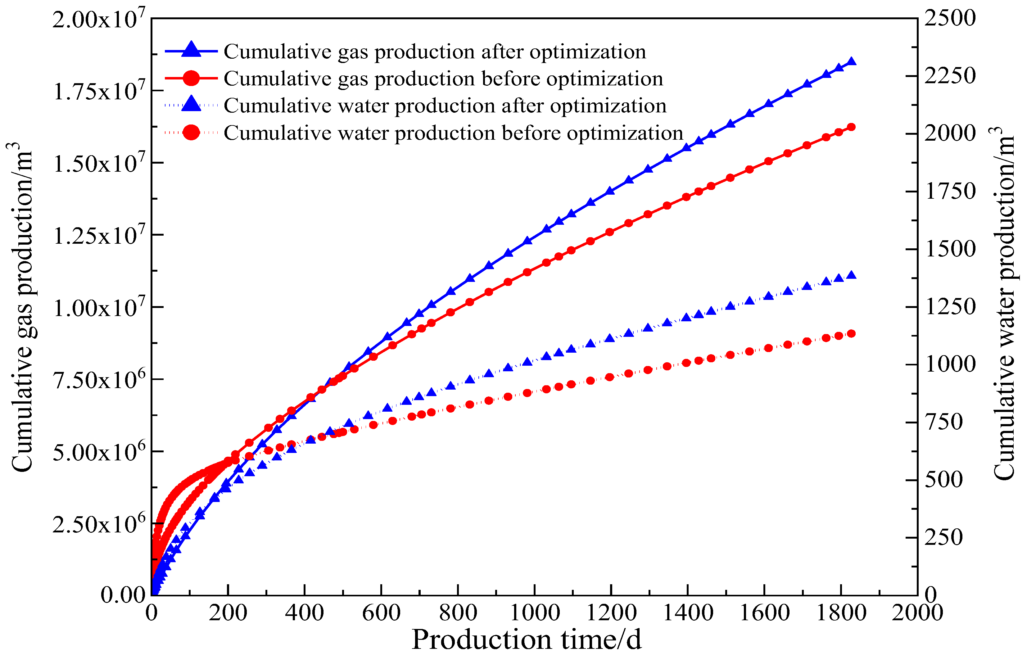
Based on the simulation results shown in Figure 2 and Figure 7, we conducted a production simulation for gas and water production after hydraulic fracturing, and the results are presented in Figure 8. The production simulation results of Figure 5 demonstrate that after fracturing parameter optimization, the single-well gas production rate has significantly increased, with the five-year cumulative gas production augmented by 2 million m3, accompanied by an increase in water production of 250 m3. Therefore, the comprehensive analysis above indicates that hydraulic fracturing in deep coalbed methane reservoirs requires the optimal selection of fracturing parameters, control of fracture height, and expansion of the fracture’s control range within the coal seam, thereby effectively enhancing gas production.

Figure 8.
Production simulation results of Combination 1 before and after optimizing fracturing parameters.
3.2. Discussion of Combination 2 Simulation Results
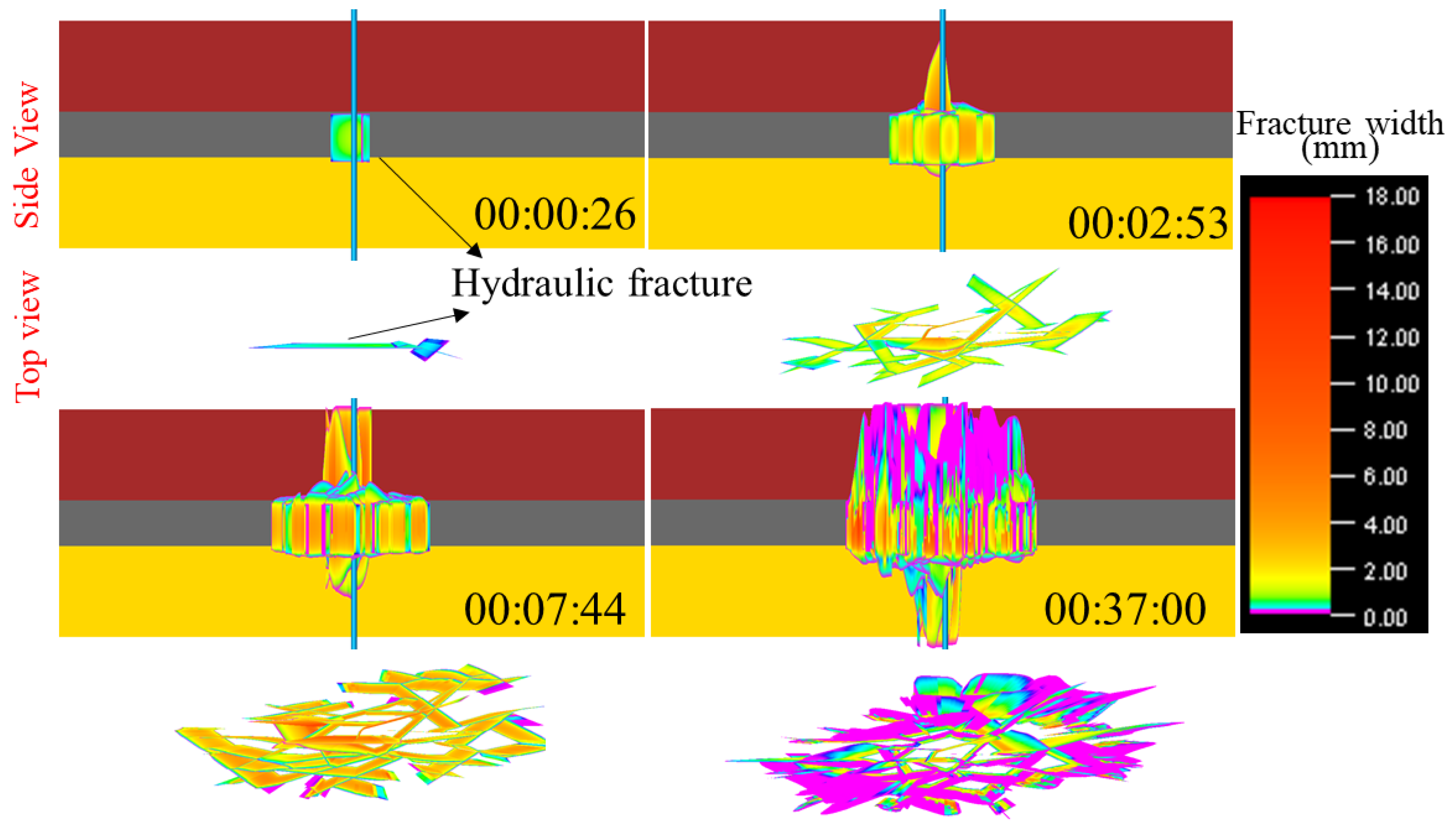
Figure 9 illustrates the variation of the vertical fracture extension morphology over time steps for Combination 2 under the original pumping schedule used in the field (Appendix A–Table A1). As shown in Figure 9, similar to Combination 1, After the crack initiation from the fracturing cluster, the fracture does not propagate vertically through the cap rock sandstone and the bottom rock mudstone. With the injection of fracturing fluid, at a time step of 2 min and 53 s, the primary fracture near the wellbore begins to propagate into the caprock sandstone. However, unlike Combination 1, the primary fracture does not extend into the floor mudstone at this stage. At a time step of 7 min and 44 s, some fractures near the wellbore have crossed into the middle region of the floor mudstone and the top of the caprock sandstone. At the current developmental phase, a multitude of subsidiary fracture branches have propagated, culminating in the emergence of an intricate fracture architecture At the end of the pumping schedule, a large number of fractures in the direction of primary fracture propagation have crossed into the caprock sandstone, and the fracture width in the upper section is generally smaller than that in the coal seam. However, only the hydraulic fractures near the wellbore have extended into the floor mudstone. Overall, under the field pumping schedule, compared to Combination 1, Combination 2 exhibits more significant penetration into the caprock sandstone, while the penetration into the floor mudstone is less pronounced.

Figure 9.
Vertical propagation morphology of hydraulic fractures at different time steps in Combination 2 (Original pump schedule in the field).
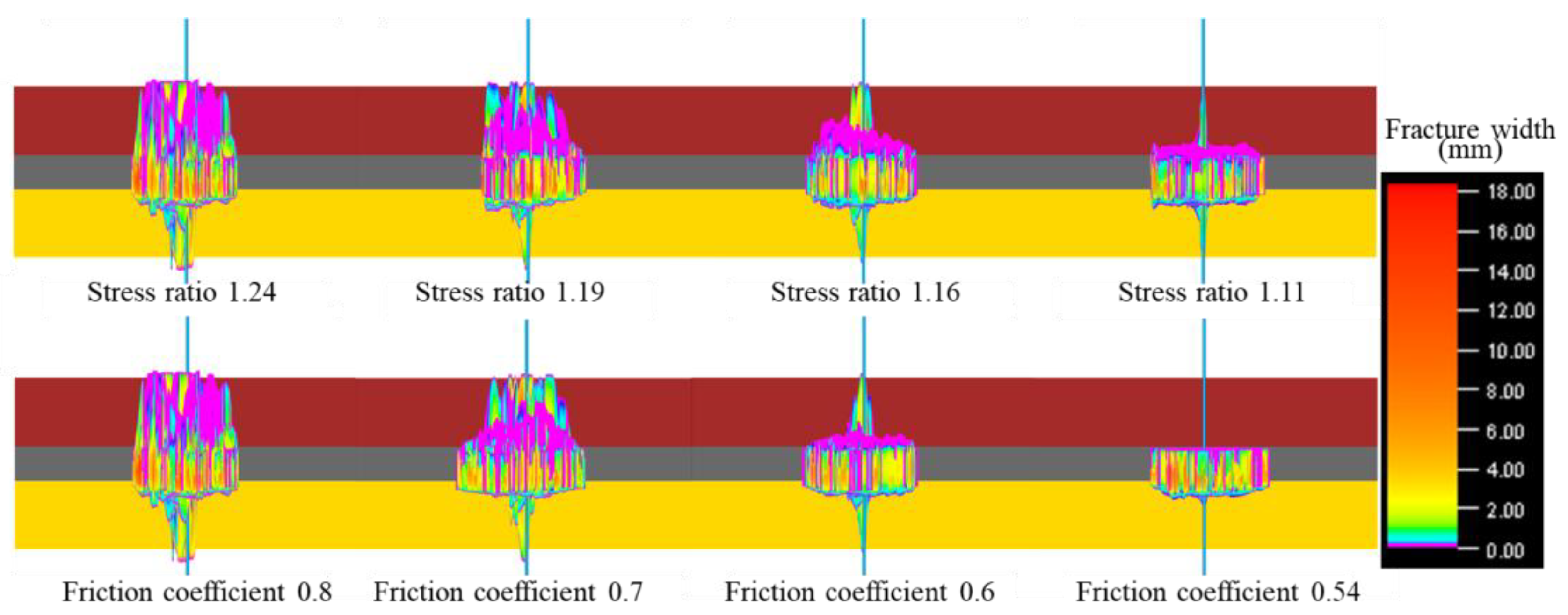
Figure 10 and Figure 11 illustrate the effects of different parameters on the vertical propagation morphology of hydraulic fractures when the roof and floor strata are sandstone and mudstone, respectively. As shown in Figure 10, both the stress ratio and friction coefficient significantly influence the through-layer penetration process of hydraulic fractures into the roof sandstone. As the stress ratio decreases, the extent of hydraulic fracture through-layer into the caprock sandstone is substantially reduced. When the ratio of the vertical principal stress (SV) to the minimum horizontal principal stress (Sh) is 1.11, the hydraulic fractures are completely confined within the coal seam. With a decrease in the friction coefficient, the penetration of hydraulic fractures into the caprock sandstone gradually weakens. When the friction coefficient is less than 0.54, only the primary fractures near the wellbore penetrate into the caprock sandstone, while the hydraulic fractures are predominantly confined within the reservoir (coal seam). The results in Figure 11 demonstrate that for the floor mudstone, when the bedding density is as low as 20 layers/meter, it can completely prevent hydraulic fractures from penetrating into the floor mudstone. Compared with Combination Scheme 1, the bedding in Combination Scheme 2 exhibits a significant influence on the penetration process of hydraulic fractures into the floor mudstone. Additionally, the penetration extension of hydraulic fractures near the wellbore into the floor mudstone is effectively constrained with a decrease in the stress ratio. However, similar to Combination 1, the friction coefficient of the floor mudstone has a minimal effect on the hydraulic fracture through-layer.

Figure 10.
Effects of different parameters of cap rock sandstone on the vertical propagation of hydraulic fractures in Combination 2.

Figure 11.
Effects of different parameters of bottom rock mudstone on the vertical propagation of hydraulic fractures in Combination 2.
The simulation results of Figure 12 and Figure 13 provide the foundation for our systematic analysis of the influence laws of different fracturing parameters and fracturing fluid systems on the propagation morphology of Combination 2 hydraulic fractures. As depicted in Figure 12, with the reduction in fracturing fluid injection rate, the hydraulic fractures around the wellbore exhibit a significant decrease in penetration through the bottom shale layer. Reducing the fracturing fluid injection rate in the coal seam section can effectively retard the vertical fracture propagation. However, the reduction in fracturing fluid injection rate has a relatively limited effect on the hydraulic fracture through-layer through the cap rock sandstone. As the sand concentration decreases, the hydraulic fracture’s vertical penetration through both the cap rock sandstone and the bottom shale layer significantly weakens. A reasonable reduction in sand concentration can effectively confine the hydraulic fracture within the coal seam section. As the total fracturing fluid volume decreases, the fracture through-layer around the wellbore through the cap rock sandstone remains relatively severe, but the fracture through-layer through the bottom shale gradually weakens. As shown in Figure 13, similar to Combination 1, the tendency of fractures to vertically penetrate through the roof and floor strata is suppressed with the decrease in fracturing fluid viscosity. A low-viscosity fracturing fluid system can form a larger and more complex fracture network within the reservoir. In comparison to Combination 1, the extent of fracture through-layer propagation becomes more severe under high-viscosity fracturing fluids.

Figure 12.
Effects of different fracturing parameters on the propagation morphology of hydraulic fractures in Combination 2.

Figure 13.
Effects of fracturing fluid system on the propagation morphology of hydraulic fractures in Combination 2.
Through the single-factor analysis of Figure 12 and Figure 13, we ultimately determined the optimal fracturing fluid parameters: an injection rate of 20 m3/min, a sand concentration of 0.6 times the original concentration, a fracturing fluid viscosity range of 1 mPa·s to 40 mPa·s, and a total fracturing fluid volume of 2220 m3. Hydraulic fracture propagation simulations were conducted using the aforementioned optimal fracturing parameters, and the results are shown in Figure 14. Comparing Figure 9 and Figure 14, it can be observed that after the optimization of fracturing parameters, the time for hydraulic fractures to propagate through the layers around the wellbore is delayed, and the extent of vertical fracture propagation is significantly reduced. With the injection of fracturing fluid, the occurrence of branch fractures penetrating through the layers is effectively suppressed. Only the main fracture near the wellbore exhibits significant penetration through the cap rock sandstone, while fracture through-layer through the bottom shale is almost completely restricted. Overall, the optimized fracturing parameters can effectively reduce the vertical penetration of fractures through the cap rock sandstone and bottom rock mudstone in Combination 2, while increasing the complexity of the fracture network.
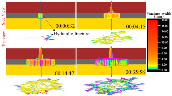
Figure 14.
Vertical propagation morphology of hydraulic fractures at different time steps in Combination 2 (After optimizing the pump schedule).
Based on the simulation results in Figure 9 and Figure 14, we conducted production simulations for gas and water output after fracturing, the results are shown in Figure 15. From the production simulation show in Figure 15, it can be observed that after the optimization of fracturing parameters, single-well natural gas production increased significantly. The cumulative gas production over 5 years rose by 4.3 million m3, while water production increased by only 855 m3.
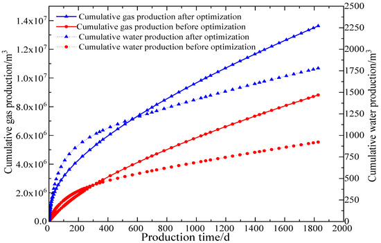
Figure 15.
Production simulation results of Combination 2 before and after optimizing fracturing parameters.
3.3. Discussion of Combined Simulation 3 Results
Figure 16 shows the variation in the longitudinal extension morphology of the hydraulic fracture over time steps under the original pumping schedule used in the field (Appendix A–Table A1) for Combined Simulation 3. As shown in Figure 16, similar to Combined Simulation 2, after crack initiation from the fracturing cluster, the hydraulic fracture does not propagate vertically through the cap rock limestone or the bottom rock sandstone. With the injection of fracturing fluid, at the time step of 3 min and 12 s, the main fracture near the wellbore begins to propagate through the cap rock mudstone. With the injection of fracturing fluid, at the time step of 3 min and 12 s, the main fracture near the wellbore begins to propagate through the cap rock limestone. By the time step of 9 min and 31 s, the main fracture near the wellbore has propagated to the end of the cap rock limestone, and some branch fractures begin to penetrate the cap rock limestone. However, the main fracture does not significantly propagate into the bottom sandstone. At the end of the pumping schedule, the main fracture and branch fractures form a complex fracture network system, with a large number of fractures penetrating the cap rock limestone. Overall, under the field pumping schedule, compared to Combined Simulations 1 and 2, the penetration of the cap rock limestone in Combined Simulation 3 is more significant, while the penetration of the bottom sandstone is not as severe.

Figure 16.
Vertical propagation morphology of hydraulic fractures at different time steps in Combination 3 (Original pump schedule in the field).
Figure 17 and Figure 18 illustrate the effects of different parameters on the longitudinal extension morphology of hydraulic fractures in the cap rock limestone and bottom sandstone. As illustrated in Figure 17, the hydraulic fracture’s penetration through the cap rock is significantly affected by both the stress ratio and the friction coefficient of the cap rock limestone. When the stress ratio and friction coefficient are relatively low, they can effectively restrict the propagation of the hydraulic fracture through the cap rock limestone. As shown in Figure 18, as the stress ratio decreases, the hydraulic fractures near the wellbore, which would originally propagate into the bottom sandstone, are confined within the coal seam interval. In contrast to the cap rock limestone formations, hydraulic fractures adjacent to the wellbore demonstrate persistent extension into the underlying sandstone strata under reduced frictional resistance conditions. The influence of the rock friction coefficient on the fracture’s capacity to traverse the basal sandstone formation remains notably insignificant.

Figure 17.
Effects of different parameters of cap rock limestone on the vertical propagation of hydraulic fractures in Combination 3.
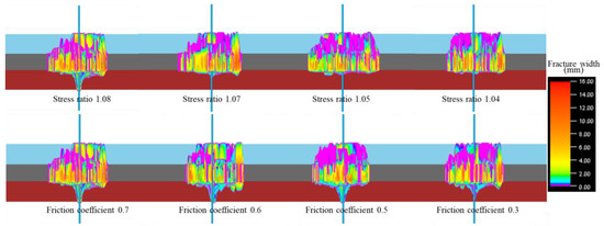
Figure 18.
Effects of different parameters of bottom rock sandstone on the vertical propagation of hydraulic fractures in Combination 3.
We analyzed the effects of different fracturing parameters and fracturing fluid systems on the extension morphology of the hydraulic fractures in Combined Simulation 3, as shown in Figure 19 and Figure 20. As depicted in Figure 19, the hydraulic fracture’s penetration capacity through the caprock limestone formation exhibits progressive attenuation in correlation with reductions in fracturing fluid injection rates. Reducing the injection rate can effectively decrease the longitudinal penetration of the hydraulic fracture through the cap rock. In addition, as shown in Figure 19, with the decrease in sand concentration and total fracturing fluid volume, the penetration of the fractures through both the cap rock limestone and the bottom sandstone gradually weakens. While maintaining the required fracture network-controlled volume, it is possible to appropriately reduce the sand concentration and total fracturing fluid volume in order to control the height of the hydraulic fractures. As shown in Figure 20, similar to Combined Simulations 1 and 2, with a decrease in the viscosity of the fracturing fluid system, the longitudinal penetration of the fractures through both the cap rock and bottom rock is significantly suppressed. The utilization of reduced-viscosity fracturing fluids promotes the development of expansive intricate fracture networks throughout the geological formation.
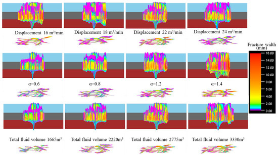
Figure 19.
Effects of different fracturing parameters on the propagation morphology of hydraulic fractures in Combination 3.

Figure 20.
Effects of fracturing fluid system on the propagation morphology of hydraulic fractures in Combination 3.
Through the single-factor analysis of Figure 19 and Figure 20, we ultimately determined the optimal fracturing parameters: a fracturing fluid injection rate of 16 m3/min, a sand concentration of 0.6 times the original sand concentration, a fracturing fluid system viscosity range of 1 mPa·s to 40 mPa·s, and a total fracturing fluid volume of 2775 m3. Hydraulic fracture extension simulations were conducted using these optimized fracturing parameters, and the results are shown in Figure 21. By comparing Figure 16 and Figure 21, it can be observed that after optimizing the fracturing operational parameters, the penetration of the hydraulic fractures is significantly reduced, with the fractures being confined to the coal seam interval for propagation. Overall, the optimization of fracturing operational parameters has a very significant effect on controlling the fracture height in Combined Simulation 3.

Figure 21.
Vertical propagation morphology of hydraulic fractures at different time steps in Combination 3 (After optimizing the pump schedule).
Based on the simulation results in Figure 16 and Figure 21, we conducted a production simulation for gas and water production after fracturing, as shown in Figure 22. The production simulation results in Figure 22 demonstrate that, after optimizing the fracturing parameters, the natural gas production per well is significantly increased. The cumulative gas production over 5 years increased by 1.3 million m3, while the water production increased by only 675 m3.
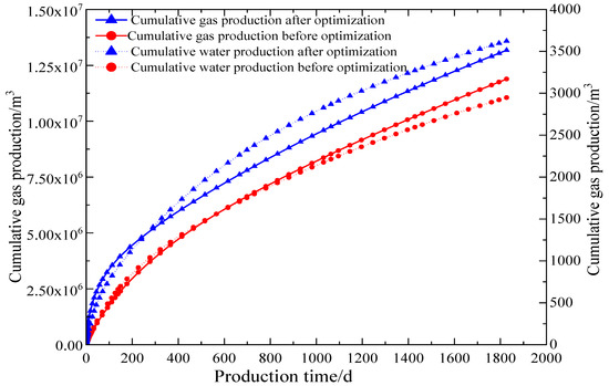
Figure 22.
Production simulation results of combination 3 before and after optimizing fracturing parameters.
4. Conclusions
A numerical simulation model for hydraulic fracture propagation in directional wells was developed, taking into account the characteristics of deep coalbed methane reservoirs with three different lithological combinations. Using this model, the influence mechanisms of stress ratio, layer density, and rock friction coefficient on hydraulic fracture through-layer were studied. The impact of fracturing operational parameters on the longitudinal extension morphology of hydraulic fractures was also investigated. The main findings of the study are as follows:
- (1)
- During the fracturing process in coal seams, hydraulic fractures first propagate from the wellbore and penetrate the cap rock or bottom rock of the coal seam, simultaneously initiating branch fractures that form a complex fracture network. The branch fractures may penetrate the cap rock and bottom rock, but after penetration, the overall fracture width remains relatively small.
- (2)
- Under different lithological combinations, the effects of layer density, stress ratio, and rock friction coefficient on hydraulic fracture through-layer vary. When the layer distribution in the mudstone is relatively dense, it can effectively restrict fracture through-layer. A smaller stress ratio and rock friction coefficient are favorable for preventing fractures from propagating through the cap rock or bottom rock.
- (3)
- Reducing the fracturing fluid injection rate and sand concentration, while selecting an appropriate total fracturing fluid volume, can effectively control the hydraulic fracture’s ability to propagate through the cap rock or bottom rock of the coal seam. A low-viscosity fracturing fluid system, compared to a high-viscosity fracturing fluid system, can effectively weaken the fracture through-layer effect and initiate more natural fractures within the coal seam interval.
- (4)
- For deep coalbed methane reservoirs with different lithological combinations, optimizing the fracturing operational parameters can increase the complexity of the fracture network within the coal seam interval and effectively control the stimulated volume. The cumulative gas production per well over 5 years can be increased by more than 1 million cubic meters.
In future research, we will integrate field hydraulic fracturing monitoring data to validate and optimize the numerical simulation results. The focus will be on investigating the influence mechanisms of rock heterogeneity, fracturing treatment parameters, and cleat distribution on fracture network complexity and post-fracture productivity. Through a series of studies, we aim to develop an optimized hydraulic fracturing design theory tailored for deep coalbed methane reservoirs in China.
Author Contributions
Conceptualization, L.Q. (Lianlian Qiao) and E.L.; methodology, D.S. and L.Q. (Lianlian Qiao); software, Q.D. and X.B.; validation, L.Q. (Lianlian Qiao) and E.L.; formal analysis, X.S. and H.W.; investigation, D.S.; resources, L.Q. (Linsheng Qiao); data curation, Z.W.; writing—original draft preparation, D.S.; writing—review and editing, D.S. and L.Q. (Lianlian Qiao); visualization, L.Q. (Linsheng Qiao); supervision, D.Z.; project administration, E.L.; funding acquisition, H.W. and D.Z. All authors have read and agreed to the published version of the manuscript.
Funding
This research was funded by the National Natural Science Foundation of China, grant number U23B2089, and the Shaanxi Provincial Natural Science Basic Research Program Project, grant number 2024JC-YBQN-0554, Scientific Research Program Funded by Shaanxi Provincial Education Department (Program No. 24JK0597).
Data Availability Statement
The original contributions presented in this study are included in the article. Further inquiries can be directed to the corresponding authors.
Conflicts of Interest
Authors Lianlian Qiao, Erhu Liu, Dong Sun, Qiaosen Dong, Linsheng Qiao and Xiaofang Bai were employed by the company Shaanxi Yanchang Petroleum (Group) Co., Ltd. The remaining authors declare that the research was conducted in the absence of any commercial or financial relationships that could be construed as a potential conflict of interest.
Abbreviations
This document employs the listed acronyms and abbreviations throughout its technical content.
| CBM | coalbed methane |
Appendix A
Table A1.
Field pump schedule for hydraulic fracturing in deep coal and rock reservoirs.
Table A1.
Field pump schedule for hydraulic fracturing in deep coal and rock reservoirs.
| Fracturing Procedure | Fluid Type | Injection Volume (m3) | Proppant Type | Sand Concentration (kg/m3) | Injection Rate (m3/min) |
|---|---|---|---|---|---|
| Pre-Fluid | Active Water | 20 | 2 | ||
| 15% Hydrochloric Acid | 15 | 2 | |||
| Active Water | 10 | 4 | |||
| High-viscosity Slickwater (55.0 mPa·s) | 120 | 22 | |||
| Low-viscosity Slickwater (1.0 mPa·s) | 20 | 200-mesh quartz sand | 88.10 | 22 | |
| High-viscosity Slickwater | 100 | 22 | |||
| Low-viscosity Slickwater | 33.3 | 200-mesh quartz sand | 105.83 | 22 | |
| High-viscosity Slickwater | 90 | 22 | |||
| Low-viscosity Slickwater | 42.9 | 200-mesh quartz sand | 123.22 | 22 | |
| High-viscosity Slickwater | 80 | 22 | |||
| Proppant-Laden Fluid | Medium-viscosity Slickwater (25.0 mPa·s) | 100 | 200-mesh quartz sand | 176.20 | 22 |
| Medium-viscosity Slickwater | 108.3 | 200-mesh quartz sand | 211.51 | 22 | |
| Medium-viscosity Slickwater | 121.4 | 200-mesh quartz sand | 246.74 | 22 | |
| Medium-viscosity Slickwater | 178.6 | 100-mesh quartz sand | 224.22 | 22 | |
| Medium-viscosity Slickwater | 200 | 100-mesh quartz sand | 256.30 | 22 | |
| Medium-viscosity Slickwater | 194.4 | 100-mesh quartz sand | 288.40 | 22 | |
| Medium-viscosity Slickwater | 200 | 100-mesh quartz sand | 304.35 | 22 | |
| Medium-viscosity Slickwater | 200 | 100-mesh quartz sand | 320.37 | 22 | |
| Medium-viscosity Slickwater | 200 | 100-mesh quartz sand | 336.39 | 22 | |
| Medium-viscosity Slickwater | 204.5 | 100-mesh quartz sand | 352.48 | 22 | |
| Medium-viscosity Slickwater | 120 | 40/70-mesh quartz sand | 334.00 | 22 | |
| Medium-viscosity Slickwater | 142.9 | 40/70-mesh quartz sand | 350.59 | 22 | |
| Medium-viscosity Slickwater | 172.7 | 30/50-mesh quartz sand | 373.61 | 22 | |
| Medium-viscosity Slickwater | 75 | 30/50 Mesh Ceramic Proppant + Coated Ceramic Proppant | 320.10 | 22 | |
| Displacement Fluid | Low-viscosity Slickwater | 26 | 22 | ||
| Total | 2775 |
References
- Li, Y.; Wang, Y.; Ding, J.; Yu, J.; Wu, P.; Song, Y. Pore-Scale Permeability Characteristics of Deep Coalbed Methane Reservoirs. Energy Fuels 2024, 38, 16149–16158. [Google Scholar] [CrossRef]
- Chen, B.; Li, S.; Tang, D.; Pu, Y.; Zhong, G. Evaluation of recoverable potential of deep coalbed methane in the Linxing Block, Eastern Margin of the Ordos Basin. Sci. Rep. 2024, 14, 9192. [Google Scholar] [CrossRef] [PubMed]
- Wang, X.; Hou, S.; Wang, X.; Yuan, Y.; Dang, Z.; Tu, M. Geological and hydrological controls on the pressure regime of coalbed methane reservoir in the Yanchuannan field: Implications for deep coalbed methane exploitation in the eastern Ordos Basin, China. Int. J. Coal Geol. 2024, 294, 104619. [Google Scholar] [CrossRef]
- Zhang, C.; Li, M.; Hu, Q.; Jia, H.; Li, K.; Wang, Q.; Yang, R. Moderately deep coalbed methane reservoirs in the southern Qinshui Basin: Characteristics and technical strategies for exploitation. Coal Geol. Explor. 2024, 52, 122–133. [Google Scholar] [CrossRef]
- Fu, H.; Huang, L.; Hou, B.; Weng, D.; Guan, B.; Zhong, T.; Zhao, Y. Experimental and Numerical Investigation on Interaction Mechanism Between Hydraulic Fracture and Natural Fracture. Rock Mech. Rock Eng. 2024, 57, 10571–10582. [Google Scholar] [CrossRef]
- Huang, L.; Liao, X.; Fan, M.; Wu, S.; Tan, P.; Yang, L. Experimental and numerical simulation technique for hydraulic fracturing of shale formations. Adv. Geo-Energy Res. 2024, 13, 83–88. [Google Scholar] [CrossRef]
- Yu, J.; Li, N.; Hui, B.; Zhao, W.; Li, Y.; Kang, J.; Hu, P.; Chen, Y. Experimental simulation of fracture propagation and extension in hydraulic fracturing: A state-of-the-art review. Fuel 2024, 363, 131021. [Google Scholar] [CrossRef]
- Guo, X.; Yu, Z. Experimental and numerical simulation study on hydraulic fracture propagation law of coal seam. Pet. Sci. Technol. 2024, 42, 2063–2085. [Google Scholar] [CrossRef]
- Liao, S.; Hu, J.; Zhang, Y. Mechanism of hydraulic fracture vertical propagation in deep shale formation based on elastic–plastic model. Eng. Fract. Mech. 2024, 295, 109806. [Google Scholar] [CrossRef]
- Zhou, X.; Liu, X.; Liang, L. Analysis of Factors Influencing Three-Dimensional Multi-Cluster Hydraulic Fracturing Considering Interlayer Effect. Appl. Sci. 2024, 14, 5330. [Google Scholar] [CrossRef]
- Tan, P.; Chen, Z.-W.; Huang, L.-K.; Zhao, Q.; Shao, S.-R. Evaluation of the combined influence of geological layer property and in-situ stresses on fracture height growth for layered formations. Pet. Sci. 2024, 21, 3222–3236. [Google Scholar] [CrossRef]
- Du, B.; Zhang, F.; Zhang, C. Distinct element modeling of hydraulic fracture propagation with discrete fracture network at Gonghe enhanced geothermal system site, northwest China. J. Rock Mech. Geotech. Eng. 2024, in press. [CrossRef]
- Wang, H.; Zhou, D.; Zou, Y.; Zheng, P. Effect mechanism of seepage force on the hydraulic fracture propagation. Int. J. Coal Sci. Technol. 2024, 11, 43. [Google Scholar] [CrossRef]
- Wang, H.; Zhou, D. Mechanistic study on the effect of seepage force on hydraulic fracture initiation. Fatigue Fract. Eng. Mater. Struct. 2024, 47, 1602–1619. [Google Scholar] [CrossRef]
- Yinghao, D.; Yang, X.; Di, W.; Yan, J. A study of Hydraulic fracture propagation in laminated shale using extended finite element method. Comput. Geotech. 2024, 166, 105961. [Google Scholar] [CrossRef]
- Zhang, Z.-P.; Zou, Y.-S.; Zhu, H.-Y.; Zhang, S.-C. Investigation of interaction behavior between hydraulic fractures and gravels in heterogeneous glutenite using a grain-based discrete element method. Pet. Sci. 2025, 22, 348–369. [Google Scholar] [CrossRef]
- Fu, W.; Deng, Q.; Ge, Z.; Jia, Y.; Ma, Z.; Shang, C.; Zheng, J.; Hou, Y. Numerical Investigation of Tree-Type Hydraulic Fracturing for Balanced Permeability Enhancement of Heterogenous Coal Seams Based on the Finite-Discrete Element Method Model. ACS Omega 2024, 9, 22090–22101. [Google Scholar] [CrossRef]
- Liao, Z.; Rabiee, H.; Ge, L.; Li, X.; Yang, Z.; Xue, Q.; Shen, C.; Wang, H. Revelling pore microstructure impacts on the compressive strength of porous proppant based on finite and discrete element method. J. Mater. Sci. Technol. 2024, 211, 72–81. [Google Scholar] [CrossRef]
- Liu, X.; Tao, W.; Liu, B.; Wang, S.; Deng, W.; Fan, Y. Study on direct shear mechanical characteristics of grouted-filled jointed coal using discrete element method. Eng. Anal. Bound. Elem. 2024, 169, 106048. [Google Scholar] [CrossRef]
- Lu, S.; Jia, N. Coal seam penetration enhancement technology integrating hydraulic fracturing fracture development theory. Appl. Earth Sci. 2024, 133, 162–173. [Google Scholar] [CrossRef]
- Chen, B.; Li, S.; Tang, D. Numerical simulation study on hydraulic fracture propagation of multi-cluster fracturing of horizontal well in deep fractured coal seams. Eng. Fract. Mech. 2025, 318, 110983. [Google Scholar] [CrossRef]
- Han, L.; Zhou, X. Numerical Simulations of the Hydraulic Fracture Propagation in Poroelastic Media Using the Coupled Hydro-Mechanical Field-Enriched Finite Element Method. Rock Mech. Rock Eng. 2025, 58, 245–274. [Google Scholar] [CrossRef]
- Huang, L.; Li, B.; Wu, B.; Li, C.; Wang, J.; Cai, H. Study on the extension mechanism of hydraulic fractures in bedding coal. Theor. Appl. Fract. Mech. 2024, 131, 104431. [Google Scholar] [CrossRef]
- Lecampion, B. An extended finite element method for hydraulic fracture problems. Commun. Numer. Methods Eng. 2009, 25, 121–133. [Google Scholar] [CrossRef]
- Zheng, P.; Xia, Y.; Yao, T.; Jiang, X.; Xiao, P.; He, Z.; Zhou, D. Formation mechanisms of hydraulic fracture network based on fracture interaction. Energy 2022, 243, 123057. [Google Scholar] [CrossRef]
- Cheng, S.; Zhang, M.; Zhang, X.; Wu, B.; Chen, Z.; Lei, Z.; Tan, P. Numerical study of hydraulic fracturing near a wellbore using dual boundary element method. Int. J. Solids Struct. 2022, 239–240, 111479. [Google Scholar] [CrossRef]
- Li, P.; Liu, Y.; Cai, M.; Miao, S.; Dai, L.; Gorjian, M.J.A.i.G.-E.R. Accurate stress measurement using hydraulic fracturing in deep low-permeability reservoirs: Challenges and research directions. Adv. Geo-Energy Res. 2024, 14, 165–169. [Google Scholar] [CrossRef]
- Ismail, A.; Azadbakht, S.J.I.J.f.N.; Geomechanics, A.M.i. A comprehensive review of numerical simulation methods for hydraulic fracturing. Int. J. Numer. Anal. Methods Geomech. 2024, 48, 1433–1459. [Google Scholar] [CrossRef]
- Jahandideh, A.; Jafarpour, B. Optimization of hydraulic fracturing design under spatially variable shale fracability. J. Pet. Sci. Eng. 2016, 138, 174–188. [Google Scholar] [CrossRef]
- Starovoitova, B.N.; Golovin, S.V.; Paderin, G.V.; Shel, E.V.; Kavunnikova, E.A.; Krivtsov, A.M. Design optimization of hydraulic fracturing. IOP Conf. Ser. Earth Environ. Sci. 2018, 193, 012011. [Google Scholar] [CrossRef]
- Duplyakov, V.M.; Morozov, A.D.; Popkov, D.O.; Shel, E.V.; Vainshtein, A.L.; Burnaev, E.V.; Osiptsov, A.A.; Paderin, G.V. Data-driven model for hydraulic fracturing design optimization. Part II: Inverse problem. J. Pet. Sci. Eng. 2022, 208, 109303. [Google Scholar] [CrossRef]
- Wang, L.; Yao, Y.; Wang, K.; Adenutsi, C.D.; Zhao, G.; Lai, F. Data-driven multi-objective optimization design method for shale gas fracturing parameters. J. Nat. Gas Sci. Eng. 2022, 99, 104420. [Google Scholar] [CrossRef]
- Zhang, L.; Li, Z.; Lai, F.; Li, H.; Adenutsi, C.D.; Wang, K.; Yang, S.; Xu, W. Integrated optimization design for horizontal well placement and fracturing in tight oil reservoirs. J. Pet. Sci. Eng. 2019, 178, 82–96. [Google Scholar] [CrossRef]
- Wang, H.; Yang, S.; Zhang, L.; Xiao, Y.; Su, X.; Yu, W.; Zhou, D. Experimental Analysis of the Mechanical Properties and Failure Behavior of Deep Coalbed Methane Reservoir Rocks. Processes 2024, 12, 1125. [Google Scholar] [CrossRef]


Disclaimer/Publisher’s Note: The statements, opinions and data contained in all publications are solely those of the individual author(s) and contributor(s) and not of MDPI and/or the editor(s). MDPI and/or the editor(s) disclaim responsibility for any injury to people or property resulting from any ideas, methods, instructions or products referred to in the content. |
© 2025 by the authors. Licensee MDPI, Basel, Switzerland. This article is an open access article distributed under the terms and conditions of the Creative Commons Attribution (CC BY) license (https://creativecommons.org/licenses/by/4.0/).