Abstract
Water jet repair technology, used for gas extraction boreholes, is an effective way to improve the effect of gas extraction. Nevertheless, the effects water jets have on the repair of gas extraction boreholes are still ambiguous. To investigate the characteristics of coal breaking using water jets in gas extraction boreholes and their repair effectiveness, a mathematical model for water jet coal breaking was established and a method for determining the depth of coal breaking using water jets was proposed. The coal-breaking depth, stress distribution law, and damage distribution law under the influence of water jet pressure, jet target distance, and coal strength were investigated using numerical simulations so as to make clear the repair effects of water jets on gas extraction boreholes. The outcomes indicate the following: the depth of coal breakage increases linearly with the increase in jet pressure; the depth of coal breakage decreases inversely proportional to the increase in coal body strength; and a reverse linear correlation exists between the water jet coal-breaking depth and the jet target distance. The extent of the influence exerted by coal strength, jet pressure, and jet target distance on the depth of coal breakage diminishes successively. The scope of damage caused by water jet flow to the rock surrounding gas extraction boreholes is limited. The coal-breaking depth model, coal body stress distribution model, and damage distribution model under the influence of jet pressure, coal body strength, and jet target distance were obtained using fitting. The research findings can offer a theoretical basis and technical support for enhancing the utilization efficiency of coal seam gas extraction boreholes.
1. Introduction
Coal is of great significance to China’s economic development. However, gas disasters are an unavoidable issue in coal mine production. At present, drilling gas drainage is widely used to control gas disasters in China [1,2]. However, the effectiveness of borehole gas extraction is not satisfactory. The reason for this outcome is that the permeability of coal seams in China is extremely low due to the impact of multi-period tectonic activities. Additionally, during the gas extraction process, the weak mechanical strength of the coal body makes boreholes highly susceptible to instability, such as deformation, collapse, and closure [3,4]. These issues compromise or completely disrupt the gas extraction functionality of boreholes, making it difficult to achieve the predetermined extraction efficiency. Due to the aforementioned reasons, a significant issue has arisen: despite the large number of boreholes, the actual gas extraction volume remains limited. Repair technology used on gas extraction boreholes can prolong the life of extraction boreholes and improve the effect of gas extraction. However, this technology is not yet mature, making it difficult to effectively maintain gas extraction boreholes.
Water jet theory and technology play a crucial role in the prevention and control of gas disasters. They serve as an effective approach for gas disaster prevention and control, while also providing a theoretical foundation for gas extraction borehole repair technology [5,6]. Currently, extensive research has been conducted on the principles and mechanisms of rock fragmentation by water jets. X. Sun et al. [7] demonstrated that the crushing efficiency of water jets on rocks results from the combined action of water jet impact load and quasi-hydrostatic pressure. A German scholar, A.W. Momber [8], carried out a water jet impact test on six kinds of rock materials with different compressive strengths, concluding that brittle materials are completely elastic to impact response. Y. Xue et al. [9,10] restored the damage field of coal samples impacted by water jets and simulated the water jet breaking process according to an ALE algorithm. Y. Gao [11,12] employed experimental and simulation approaches to acquire the principle by which coal is crushed by water jets under the effect of coal wall roughness and jet target distance. X. Liu et al. [13] studied the influences of jet velocity and jet angle on coal damage in water jet breaking coal processes using numerical simulations. H. Jiang et al. [14] performed a simulation on the process of rock breakage; their results indicate that the discontinuous water jet possessed more favorable rock-crushing capabilities in contrast to the continuous high-pressure water jet at an equivalent energy level. M. Liu [15] and Z. Wang et al. [16] used field investigations and experimental research to obtain the coal-breaking conditions of water jets and their penetration enhancement effects, concluding that the effects of coal unloading, penetration enhancement, and punching radius were positively correlated. C. Hao et al. [17] simulated the coal-breaking effect of submerged and non-submerged jets, concluding that the coal-breaking depths of submerged jets under the same impact times were about 21% of those in non-submerged environments. Y. Pan et al. [18] examined the impacts of jet velocity and pulse spacing on coal breaking using a numerical simulation. J. Zhang et al. [19] delved into the repercussions of nozzles on the velocity attenuation of high-pressure water jets and determined that the nozzle structure has a substantial impact on it. J. Mi et al. [20] employed post-mixed abrasive water jets to strike rocks and investigated the effects of the impact pressure and abrasive concentration on rock fragmentation. S. Xiao et al. [21] experimentally analyzed the crushing processes of shale, sandstone, and coal under the action of water jets with varying velocities. It was discovered that as the jet velocity increases, coal, sandstone, and shale exhibit different crushing patterns.
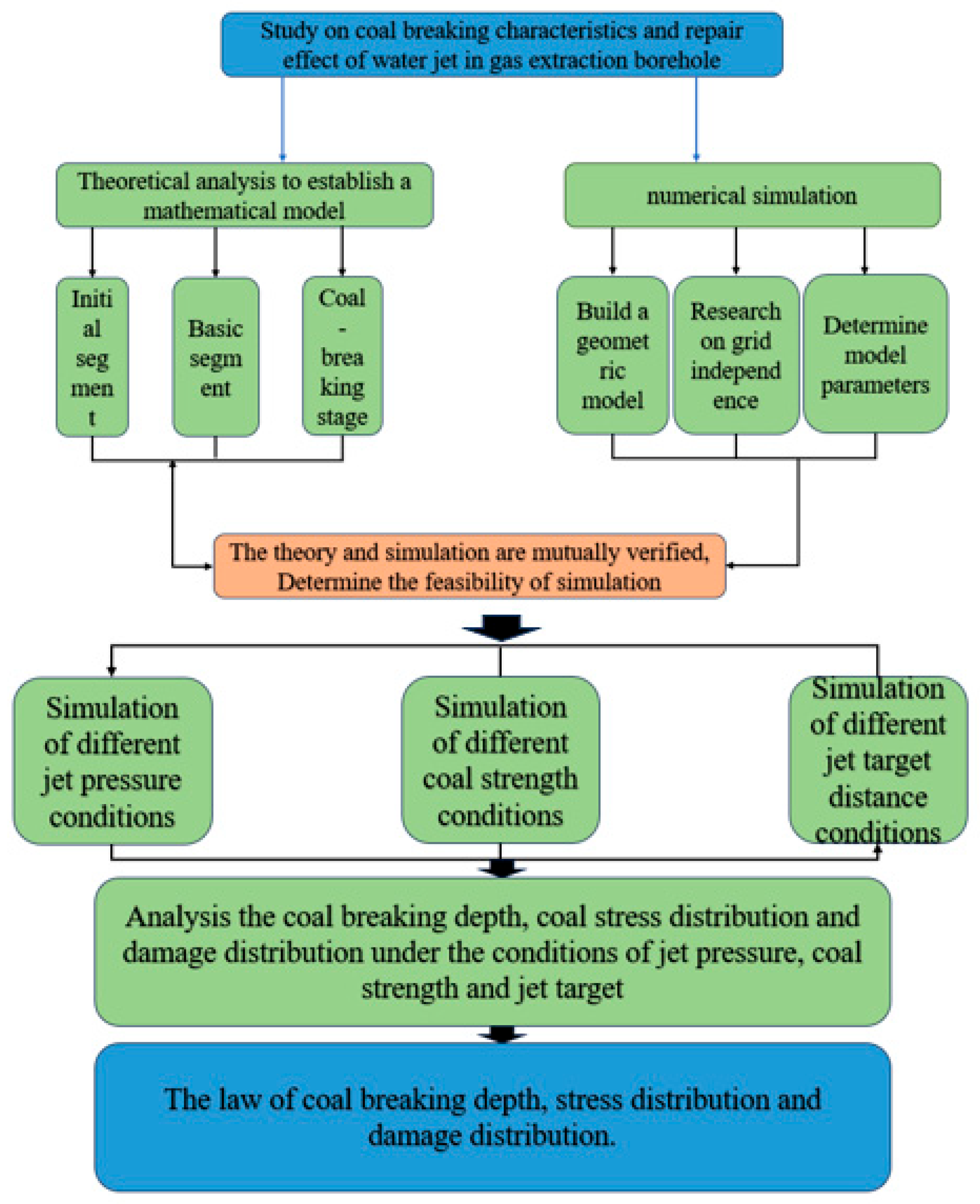
Although the theory regarding the impact of water jets on coal and rock masses has been explored and has yielded significant outcomes, the overall effects of water jet pressure, coal strength, and jet target distance on the repair of gas extraction boreholes remain uncertain. The selection of the technical parameters for repairs is still based on empirical summarization. Due to the lack of scientific theoretical guidance on repair effectiveness, the widespread application of water jet technology for gas extraction borehole repair remains challenging. In order to further understand the depth of water jet breaking coal under the comprehensive influencing factors of jet pressure, coal strength, and jet target distance in the process of water jet breaking coal, as well as the stress distribution and damage distribution of coal bodies in the process of water jet breaking coal, a mathematical model of water jet breaking coal is established, and the calculation formula of water jet breaking coal depth under the combined action of jet pressure, coal strength, and jet target distance is proposed in this paper. Then, based on the HJC ontological model (Holmquist–Johnson–Cook) of rock, the water jet coal breakage law and its repairing effect on gas extraction boreholes under the effect of water jet pressure, coal body strength, and jet target distance were investigated by using the LS-DYNA software (smp s R11.0.). The influence of jet pressure, coal strength, and jet target distance on the depth of water jet breaking coal, as well as the stress distribution law and damage distribution law of coal bodies in the process of water jet breaking coal under the influence of three factors, were explored. The research results can guide the selection of the hydraulic parameters used for the water jet repair of boreholes and provide theoretical guidance for the application of water jet repair technology in gas extraction boreholes. A flow chart of this study is shown in Figure 1.
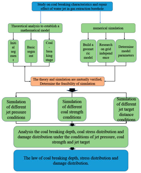
Figure 1.
Flow chart of this study.
2. Materials and Methods
2.1. Water Jet Repair Process of Gas Extraction Borehole
Xin’an Coal Mine is affiliated with Yimei Company, a subsidiary of Henan Energy and Chemical Group. The mine is affected by regional geological structures, and the main mining II-1 coal seam exhibits low permeability and a high risk of gas outbursts. Cross-seam borehole pre-drainage is the main method utilized at Xin’an Coal Mine to prevent and control gas disasters. The primary challenge associated with this technology is the rapid attenuation of borehole gas concentration. According to measurements, the concentration of borehole gas extraction in the mine decays rapidly. The average concentration of gas extraction reaches approximately about 60% within the first 24 h, within one month, it further decreases to less than 5%, and after three months, the average concentration stabilizes at around 1.4%, this rapid decline necessitates prolonged gas extraction cycles and creates operational pressure on mining face succession, significantly hindering the economic optimization of coal mining operations. Therefore, implementing water jet repair measures for gas extraction boreholes is crucial to extend their effective life cycle and ensure compliance with gas extraction standards.
Figure 2 illustrates the physical model of water jet repair in a gas extraction borehole. The gas extraction borehole shown in Figure 2 lies within the coal seam. After prolonged extraction, the process causes the deformation and instability of the borehole’s surrounding rock, leading to a reduced borehole diameter or even collapse. These issues cause a significant attenuation of gas extraction concentration, leading to reduced gas extraction efficiency. A nozzle assembly is positioned within the gas extraction borehole, aligned such that the water jet is perpendicular to the borehole wall. The high-pressure water jet impacts the borehole wall, fracturing the coal body to restore gas extraction functionality. Based on the implementation of water jet repair technology for gas extraction boreholes in Xin’an Coal Mine, the diameter of the coal seam borehole is 113 mm, the diameter of the nozzle is 1 mm, and the nozzle is perpendicular to the borehole wall.
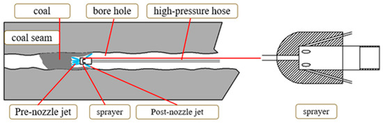
Figure 2.
Physical model of water jet repair in gas extraction borehole.
2.2. Mathematical Model of Water Jet Breaking Coal
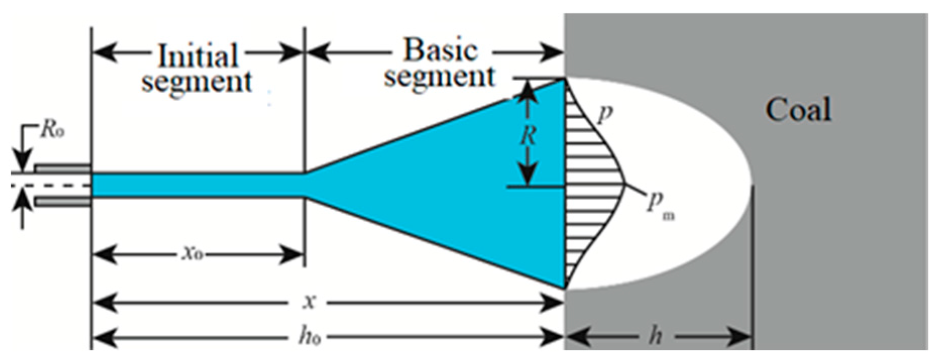
The procedure of water jet coal breakage describes the course of a high-pressure water jet impinging on coal. Due to the influence of the surrounding medium, the process also exhibits gradual energy attenuation. Based on the formation and evolution characteristics of the water jet, the process can be divided into three stages: the initial stage, the main stage, and the coal-breaking stage (Figure 3).
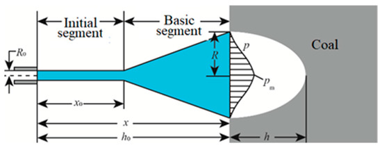
Figure 3.
Schematic diagram of water jet structure.
To simplify the study, the following fundamental assumptions are proposed when formulating the mathematical model of water jet coal breaking: The static pressure on the water jet boundary surface equals atmospheric pressure; the water jet and the ambient gas medium do not exchange energy; and external forces have no impact on the generation process. The water jet exhibits distinct development characteristics in these three stages. Therefore, separate mathematical models will be established for each stage.
(1) Initial segment
The flow characteristics of the water jet in the initial segment are associated with the Reynolds number. When the Reynolds number reaches 2 × 10⁵, the jet at the nozzle outlet has a uniform flow, and the water jet’s dynamic pressure remains constant in this segment. The initial segment length is associated with the shape of the nozzle. The length of the initial segment can be expressed [22] as follows:
where denotes the initial radius of the nozzle, m; α is a coefficient, and its range is 65~135.
(2) Basic segment
The dynamic pressure of the water jet begins to decrease in the basic section. The attenuation pattern can be analyzed using the principle of jet momentum conservation. The distribution of dynamic pressure on the axis of the jet in the basic segment can be expressed [23] as follows:
where is the dynamic pressure at the jet axis in the basic section x, MPa; is initial jet pressure, MPa; is the jet density of the axis at x position in the basic segment, kg/m3; is the jet velocity at the axis at position x in the basic segment, m/s; is the initial jet density, kg/m3; is the nozzle exit jet velocity, m/s; and x is the position of any cross-section in the basic segment, m.
Therefore, the attenuation law of dynamic pressure along the jet axis direction can be described as follows:
The distribution law of the jet flow pressure perpendicular to the jet axis at the basic section x can be presented [23] as follows:
where p is the pressure of a point on the jet cross-section of the jet at x position of the basic segment, MPa; is the diffusion radius of water jet at position x of the basic segment, mm; and .
Where R is related to the initial jet radius, which can be expressed as follows:
where is a coefficient related to the nozzle radius, generally 0.12~0.18; and is the initial jet radius, m.
By combining Equations (4)–(6), the jet pressure at the coal wall surface can be derived as follows:
(3) Coal-breaking segment
The water jet enters the coal-breaking segment upon contacting the coal wall. Based on the cavity expansion theory [24].
where M indicates the coal body crushing strength, MPa; indicates the coal body compressive strength, MPa; indicates the coal body tensile strength, MPa; is the compression-shear coefficient of coal; and E indicates elastic modulus, MPa.
Water jet remediation of gas extraction boreholes entails applying continuous jet impact loading to induce structural failure in the surrounding coal mass. This process requires that the dynamic jet pressure surpass the coal’s compressive strength, as expressed by the following:
where is the stable flow stagnation pressure generated after the liquid column impacts the coal body.
(4) Coal-breaking depth
Given the jet pressure decays radially in the jet cross-section, where the dynamic pressure reaches its maximum along the jet axis, Equation (7) can be simplified as follows:
If the target distance is , the limiting coal-crushing depth h by water jet can be expressed as follows:
where is the limit destruction depth of water jet to coal, m.
2.3. Numerical Simulation of Water Jet Breaking Coal Process
2.3.1. Numerical Simulation Model and Numerical Simulation Material Parameters
1. Water jet impact coal body model
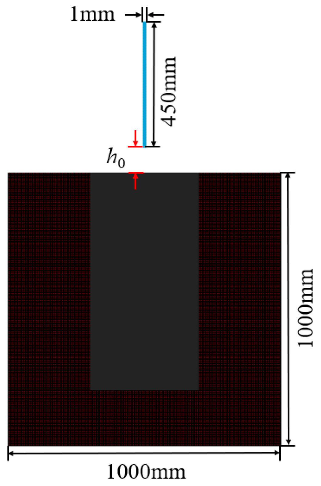
The water jet-induced coal fragmentation process was simulated using the finite element method, implemented in the LS-DYNA software platform. The geometric model of water jet coal breaking is constructed with the application of the LS-PREPOST (smp s R11.0.) preprocessing software. The high-pressure water jet was modeled as a particle beam using the Smoothed Particle Hydrodynamics (SPH) method, with each particle assigned a specific initial velocity. The NULL material model and Johnson–Holmquist Concrete (HJC) model were employed to characterize the water jet and coal behaviors, respectively. The geometric dimensions of the water jet liquid column model are 1 mm × 450 mm, while the coal body model is 1000 mm × 1000 mm. Figure 4 depicts the geometric model.

Figure 4.
Geometric model of water jet breaking coal.
2. Research on grid independence
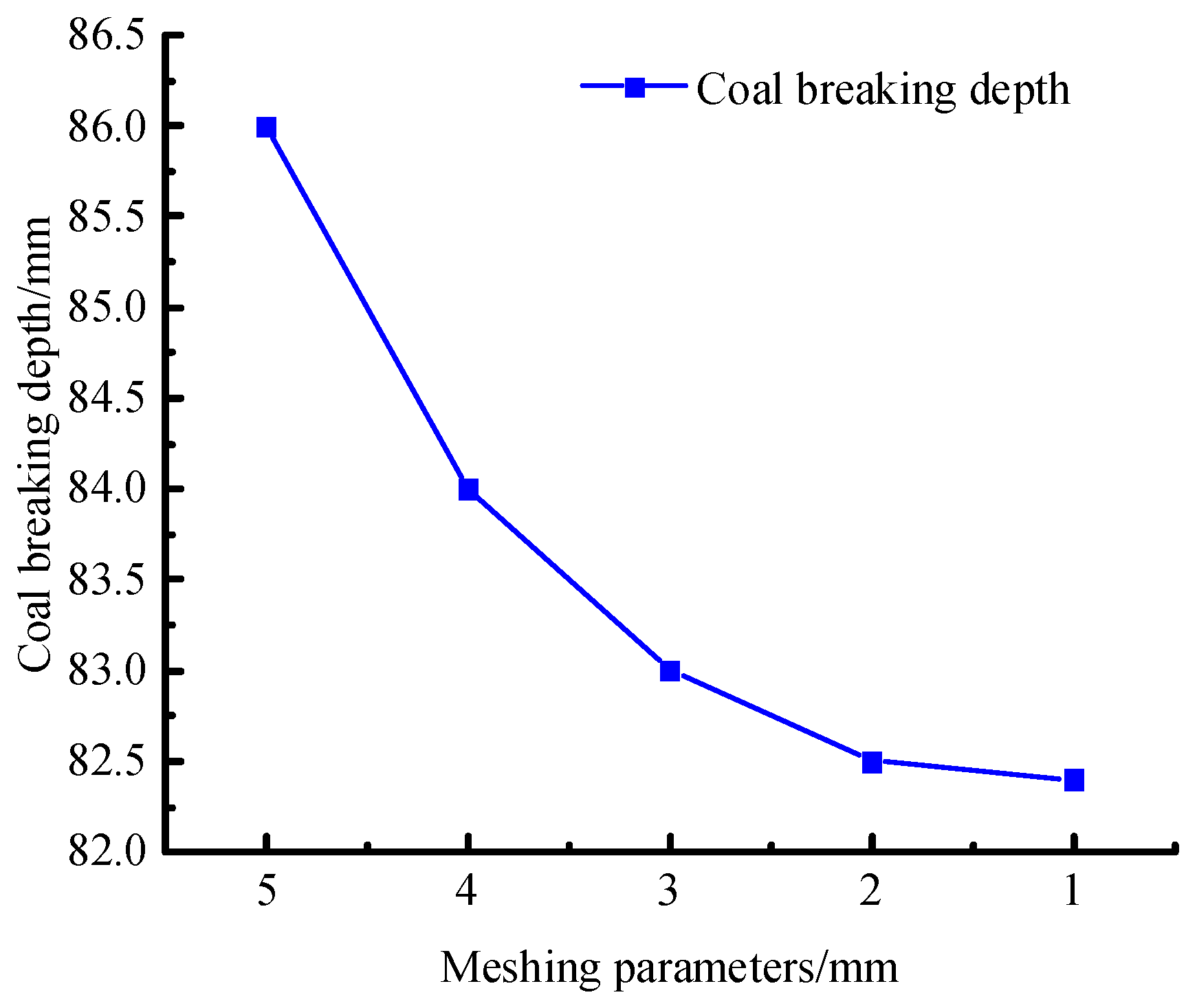
The discretized geometry for boundary condition resolution must exhibit mesh independence. To ensure the scientificness and accuracy of the water jet coal-breaking process, the grid independence of the water jet coal-breaking model was studied. The geometric model of water jet breaking coal is shown in Figure 4. The process of water jet breaking coal was simulated by using different meshing parameters (the coal strength was 8 MPa, the jet pressure was 26 MPa, and the target distance of the jet was 70 mm). The meshing parameters of the coal area were set as 5 mm, 4 mm, 3 mm, 2 mm, and 1 mm, respectively. The water jet mesh was divided into 0.2 mm. A structured square grid was employed for the numerical simulation. According to the parameter settings of Table 1 and Table 2, the process of water jet breaking coal was simulated under varying mesh resolutions. The depth of coal breaking under different grid parameters is shown in Figure 5.

Table 1.
Water jet liquid column and coal model parameters.
Table 2.
Mechanical parameters of coal under different coal strengths.
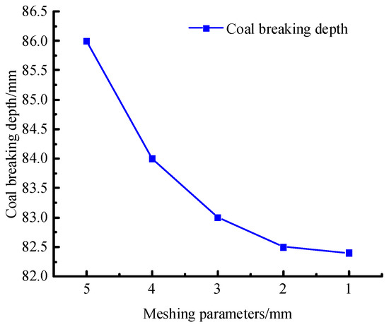
Figure 5.
Coal-breaking depth under different grid parameters.
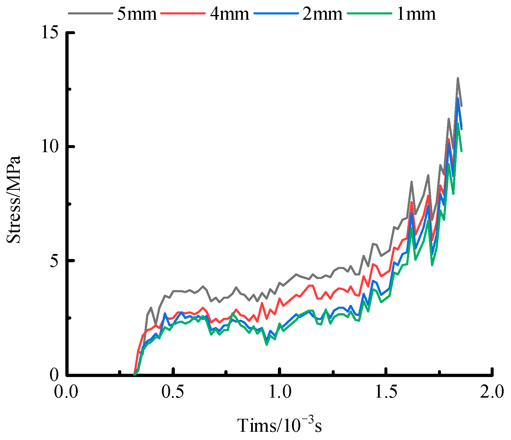
Because the study involves the depth of water jet breaking coal and the stress of coal in the process of water jet breaking coal, a coal unit located 50 mm from the coal wall was selected as the monitoring point for stress analysis. The stress variations in the selected coal unit under different mesh resolutions are presented in Figure 6.
Figure 6.
The stress under different meshing parameters.
By combining the results shown in Figure 5 and Figure 6, and analyzing the simulation results of water jet coal breaking under different grid sizes, the following conclusions can be drawn: When the mesh size is reduced to 2 mm, the change in coal-breaking depth tends to be gentle, which is almost the same as that when the mesh size is 1 mm. At the same time, when the mesh size is reduced to 2 mm, the stress on the coal unit is very small compared with that when the mesh size is 1 mm. These results indicate that the grid independence requirement is essentially satisfied at a 2 mm mesh size. Therefore, a 2 mm mesh size is selected for the coal body area in the water jet coal-breaking simulation. The meshing parameters of the model are as follows: the water jet adopts a 0.2 mm square mesh, and the coal body area adopts a 2 mm mesh for meshing.
3. Numerical simulation parameters and simulation scheme
The simulation parameters were configured based on the geological characteristics of Xin’an Coal Mine. Referring to the related literature [25], the parameters were determined as demonstrated in Table 1. The elastic modulus, Poisson’s ratio, tensile strength, and compression-shear coefficient of coal corresponding to different coal strengths are determined by the empirical equation as shown in Table 2.
This study primarily investigates the effects of jet pressure, coal strength, and jet target distance on the damage field and coal-breaking depth. The simulation scheme is presented in Table 3.
Table 3.
Scheme of numerical simulation.
Since the initial segment of the water jet is not simulated in the numerical process, the jet pressures at different target distances in the theoretical model must be converted to the jet pressure at a target distance of 0 in the simulation. The converted jet pressures are shown in Table 4.
Table 4.
Conversion of water jet pressure in the numerical model under different jet target distances.
2.3.2. Constitutive Model of the Water Jet and Coal
1. The water jet liquid column constitutive model
The water jet is regarded as an SPH particle possessing a certain velocity. The water jet selects the NULL model, and its constitutive equation satisfies the Gruneisen Equation [26]. The expression is as follows:
where is initial density; is current density; is the coefficient; , , and are coefficients; is the first-order volume modification quantity; and is the volume change rate, .
2. The constitutive model of coal material
Given that water jet breaks coal under the category of high strain rate and large deformation under high-pressure loading, the HJC [27] constitutive model is selected for the coal body.
The equation for the yield strength of the coal body described in terms of normalized equivalent stresses in the HJC [27] principal model is as follows:
where stands for the normalized equivalent stress, ; represents the normalized hydrostatic pressure, , denotes the ratio of hydrostatic pressure to static yield strength; represents the normalized strain rate, ; and D represents the damage parameter of the coal body, .
3. Results and Discussion
3.1. Model Verification
To validate the feasibility of the simulation method and the reasonableness of the selected parameters, the water jet coal-breaking process was simulated for a coal strength of 8 MPa and a jet target distance of 70 mm. Simulations were conducted under jet pressures ranging from 26 MPa to 36 MPa at 2 MPa intervals. The coal-breaking depth under different jet pressures and the coal stress at the position when the coal-breaking depth reaches 70 mm were obtained and compared with the theoretical calculation results.
3.1.1. Coal-Breaking Depth Under Different Jet Pressure
Figure 7 illustrates the damage distribution in coal under different jet pressures, and the depth of coal breaking under different jet pressures can be derived from Figure 7. Meanwhile, by substituting the parameters in Table 1 into Equation (11), the theoretical depth of coal breaking by the water jet with different jet pressures can be obtained.
Figure 7.
Damage distribution of coal under different jet pressures.
Figure 8 shows the comparison between theoretical coal-breaking depth and simulated coal-breaking depth under different jet pressures. It is evident from Figure 8 that the theoretical calculation of coal-breaking depth is basically consistent with the simulated outcomes. Furthermore, it can be concluded that the maximum difference between the theoretical calculation and the numerical simulation of coal-breaking depth is 3.2%.
Figure 8.
Theoretical and simulated coal-breaking depth under different pressure jets.
3.1.2. The Stress of Coal Under Different Jet Pressure
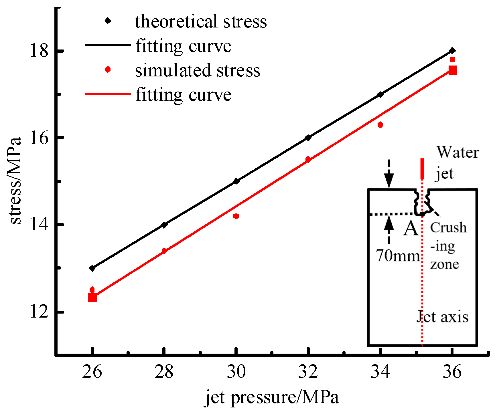
To validate the feasibility of simulating coal stress during the water jet coal-breaking process, the theoretical and simulated coal stresses were compared at a coal breakage depth of 70 mm. The theoretical coal stress can be calculated by Equation (10). Figure 9 shows the comparison between the numerical simulated coal stress and the theoretical coal stress at the point when the coal-breaking depth is 70 mm. Furthermore, it can be concluded that the maximum difference between the theoretical calculation stress and the numerical simulation stress result is 4.1%. It can be observed that the theoretical coal stress is in line with the changing trend of the simulated coal body, and the overall discrepancy is slight.

Figure 9.
Comparison of theoretical coal stress and simulated coal stress at point A under different jet pressures.
By comparing the numerical simulation results with theoretical calculations for coal breakage depth, and when the coal-breaking depth reaches 70 mm, the theoretical stress of coal at the position is compared with the simulated stress. It can be observed that the theoretical result is in line with the changing trend of the numerical simulated result, and the overall discrepancy is slight. Therefore, the simulation method is validated as feasible, and the selection of model parameters is reasonable.
3.2. Coal-Breaking Law of Water Jet Under the Influence of Jet Pressure
To evaluate the influence of water jet pressure on coal breakage efficacy, the water jet coal-breaking process was simulated according to Simulation Scheme 1. Figure 10 shows the coal-crushing depth and damage distribution at different jet pressures (the strength of coal is 6 MPa).
Figure 10.
Damage distribution of coal under different jet pressures.
Figure 11 illustrates the relationship between coal-breaking depth and jet pressure under varying coal strengths. By comparing different curves, it can be noticed that when the coal strength is relatively low, with the jet pressure increase, the increase rate of the coal-breaking depth is more pronounced, demonstrating a steeper upward trend. Conversely, when the coal strength is relatively large, the growth of the coal body-breaking depth by the water jet appears relatively flat with the increase in jet pressure. It can be concluded that when the coal strength is small, increasing the jet pressure can make the coal-breaking effect increase significantly. When the strength of coal is large, other types of jets can be considered, such as abrasive water jets.
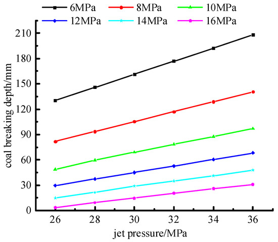
Figure 11.
The variation in coal-breaking depth with jet pressure under different coal strengths.
Studying the stress distribution and the damage distribution of coal in the process of water jet breaking coal is helpful in understanding the breaking mechanism of coal. To investigate the influence of water jet pressure on the stress and damage fields of the coal body in the coal-breaking process, when the depth of coal broken by the water jet reaches 100 mm, we chose the analysis tangent AB, then plotted the damage distribution and the stress distribution of coal of the AB. The position of the AB tangent is shown in Figure 12. (The coal strength is 6 MPa and the target distance is 70 mm). Figure 12 shows the stress distribution in coal on the tangent of AB under different jet pressures. It can be observed that the stress of the coal body declines exponentially as the distance from the coal wall increases, which is due to the fact that the water jet must constantly overcome the cohesion of the coal during the process of coal breaking.
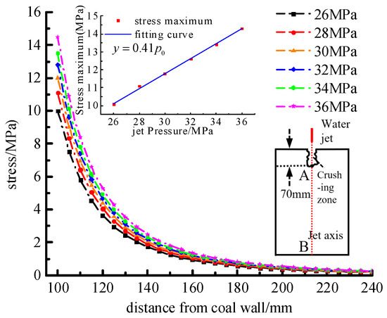
Figure 12.
The stress distribution of coal on AB line under different jet pressures.
Based on the stress distribution curves of coal under different jet pressures, it is evident that as the jet pressure increases, the stress on the coal at the same position also increases. By fitting the stress distribution curves of coal, the stress distribution of coal on AB under different jet pressures can be expressed as follows:
where is the jet pressure; is the distance between one point in the coal and the coal wall, . According to Equation (13), it can be observed that the magnitude of the stress at point A where the jet arrives is , and then it is attenuated according to the attenuation rate of .
The damage degree represents the cumulative damage degree of the internal structure of the coal body from the initial state to the current state during the process of external forces. The value range of damage degree is 0–1, where 0 signifies no damage, and 1 signifies complete damage. The larger the value is, the more serious the damage to the internal structure of the coal body is. Figure 13 illustrates the coal damage distribution on the AB tangent under different jet pressures. It can be observed that coal damage decreases exponentially with the distance from the coal wall increasing. As the water jet pressure increases, the range of coal damage expands, and the degree of damage at the same position also increases. Through fitting the curves of coal damage distribution under different jet pressures, the coal damage distribution can be pressed as follows:
where is the jet pressure; is the distance between one point in the coal and the coal wall, ; and is the distance from the critical position of damage attenuation to the coal wall, the critical position is positively correlated with the jet pressure .
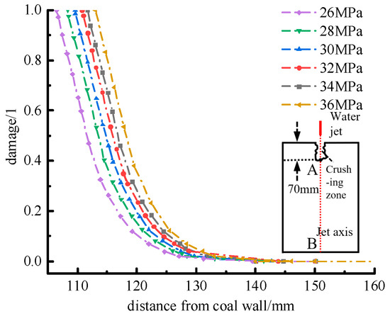
Figure 13.
The damage distribution of coal body on AB line under different jet pressure.
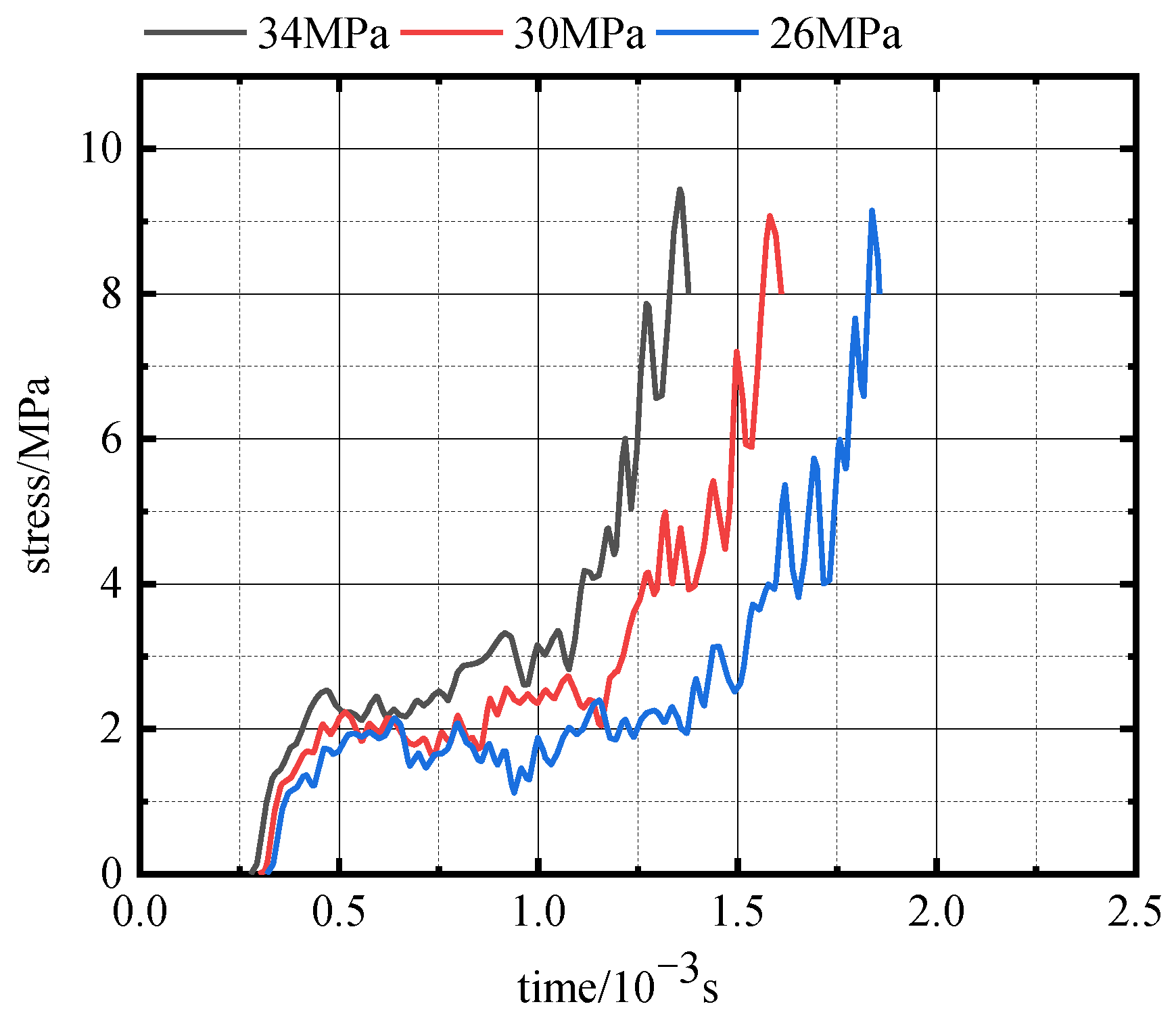
The evolution of the coal damage field can be considered as the collective damage evolution of individual coal units. By analyzing the damage evolution law of a single coal unit, we can better understand how the coal body undergoes damage evolution during the water jet coal-breaking process. To research the influence of water jet pressure on the damage evolution of the coal unit, the coal unit at the depth of 80 mm from the coal wall on the water jet axis was selected as the analysis object (Figure 14). The damage time series curve and stress time series curve of the coal unit were then plotted. (Coal strength is 6 MPa and the target distance is 70 mm.)

Figure 14.
464771#coal unit location.
Figure 15 is the damage time series curve of the coal unit under different jet pressures, and Figure 16 is the stress time series curve of the coal unit under different jet pressures. According to Figure 15 and Figure 16, it can be observed that the coal unit initially experiences damage at the jet pressure of 34 MPa, subsequently enters the damage accumulation stage, and then transitions into the complete damage stage within a relatively brief period. At the jet pressure of 26 MPa, the coal unit requires a longer time to start damage and accumulate sufficient damage to reach the complete damage stage. Additionally, it can be found that the stress corresponding to the complete damage of coal under different jet pressures is basically consistent.

Figure 15.
The damage time series curve of coal unit under different jet pressure.
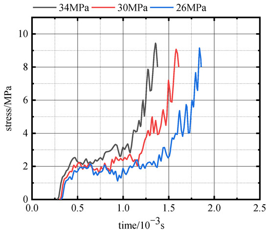
Figure 16.
The stress time series curve of coal unit under different jet pressure.
3.3. Coal-Breaking Law of Water Jet Under the Influence of Coal Strength
To explore the impact of coal strength on the coal-crushing effect, the water jet coal-breaking process was simulated according to Simulation Scheme 2. Figure 17 shows the depth of coal breaking and the coal damage characteristics under different coal body strengths at the jet target of 70 mm and the jet pressure is 36 MPa.
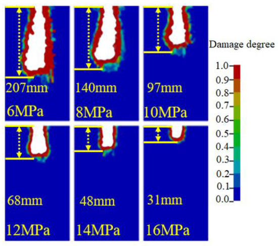
Figure 17.
Damage distribution under different coal strengths.
Figure 18 shows the variation curve of coal-breaking depth with coal strength under different jet pressures. According to Figure 18, it can be observed that under the same jet pressure, the depth of the coal breaking decreases in a non-linear manner with the coal strength increases. When the coal strength is relatively low, the depth of coal broken by the water jet decreases rapidly with the coal strength increase. In the case where the coal strength is rather high, the depth of coal breaking decreases slowly as the coal strength increases.
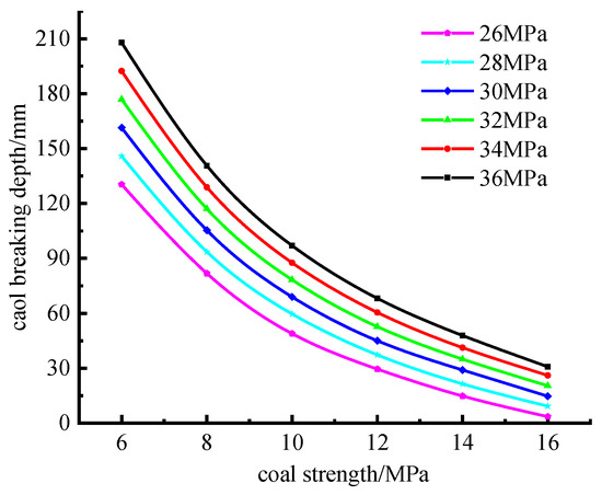
Figure 18.
The variation in coal-breaking depth with coal strength under different jet pressures.
By fitting the depth of coal breaking under different coal strengths (at a jet pressure of 36 MPa, and at the jet target distance of 70 mm), the relationship between the depth of coal breaking and the coal strength can be obtained as follows:
where is the depth of coal breaking and is coal strength. The fitting degree was 99.85%.
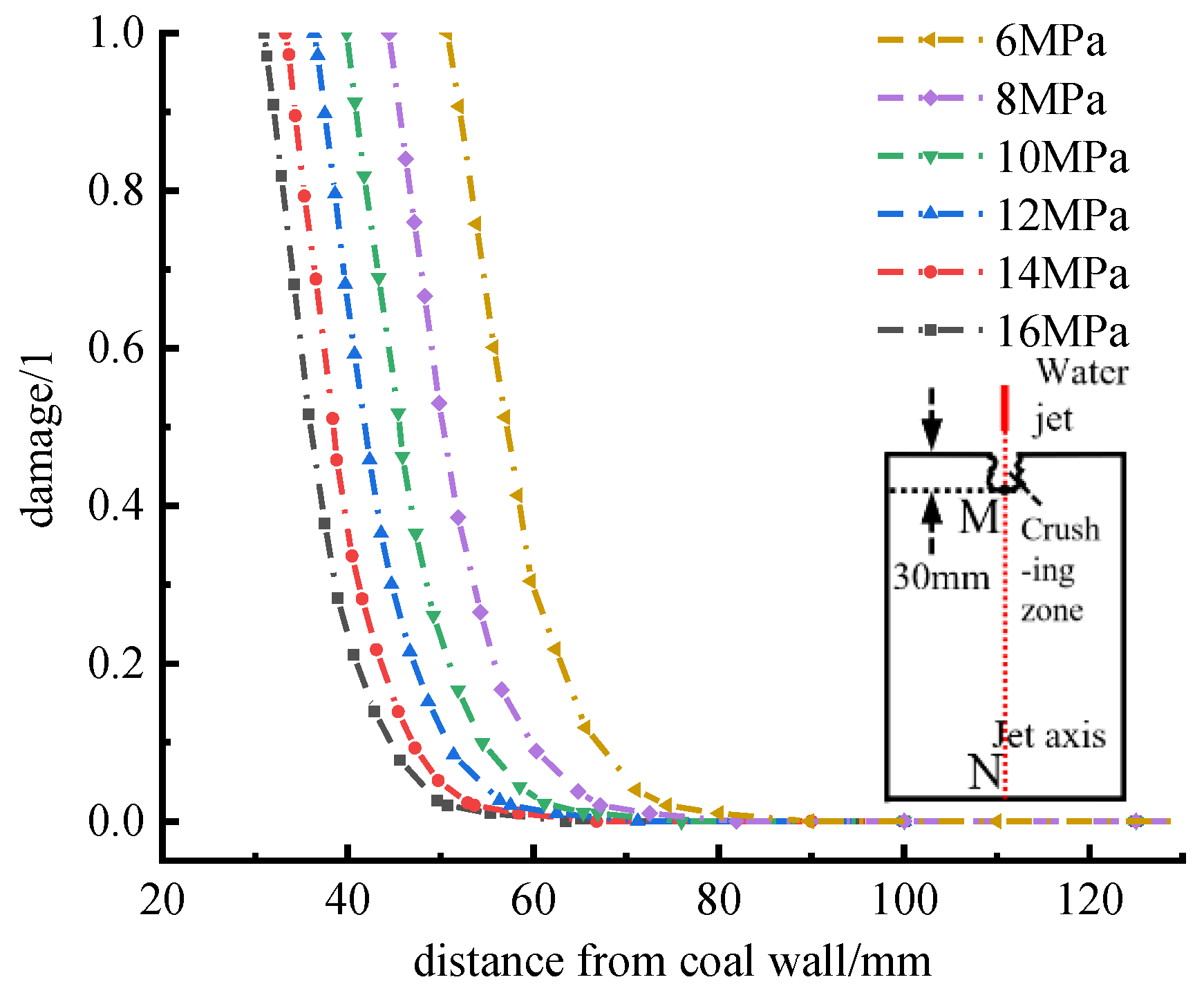
To investigate the impact of coal strength on the coal damage fields during the coal-breaking process (with a jet pressure of 36 MPa and a jet target distance of 70 mm), when the depth of coal breaking reached 100 mm, the analysis tangent MN was selected, and the damage distribution of the coal body along MN was plotted. The position of the MN tangent is shown in Figure 19. Figure 19 shows the distribution of coal damage on the MN under different coal strengths. The damage of the coal declines exponentially as the distance from the coal wall increases, and the lower the coal strength, the larger the range of complete damage of the coal, and the larger the damage degree of the coal at the same position. It can be seen that the greater the strength of the coal body, the faster the attenuation rate of the coal body. The range of coal damage during water jet repair drilling is limited. By fitting the damage distribution curves under different coal strengths, it can be concluded that
where is the distance between one point in the coal and the coal wall, , and is coal strength. is the distance from the critical position of damage attenuation to the coal wall, and the critical position is negatively correlated with the jet pressure .
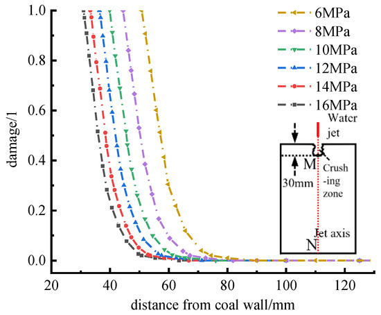
Figure 19.
The damage distribution of coal body on MN line under different coal strength.
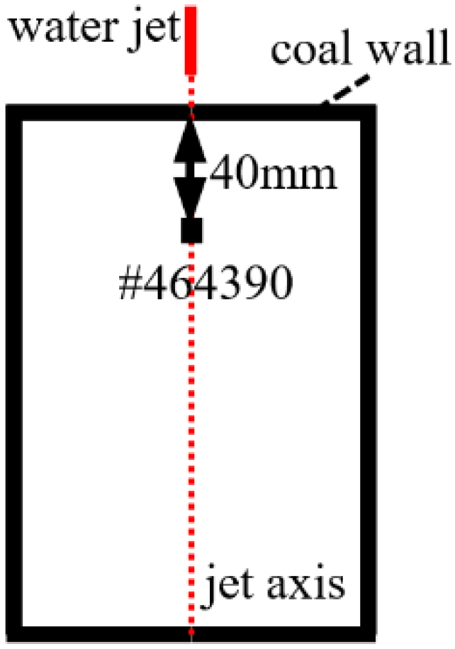
To better understand how the coal strength affects the coal unit damage evolution, (the jet pressure is 36 MPa and the jet target distance is 70 mm), the coal unit (464390#) located 40 mm from the coal wall on the jet axis was selected as the research object (Figure 20), and then the damage time series curve and stress time series curve of the coal unit under different coal strengths were plotted.
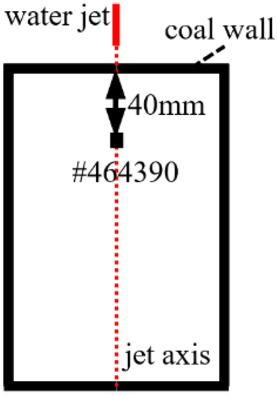
Figure 20.
464390#coal unit location.
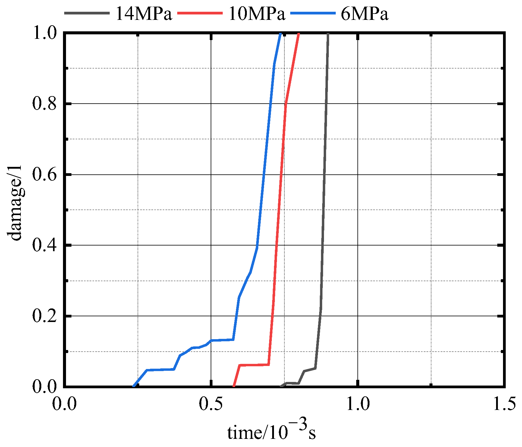
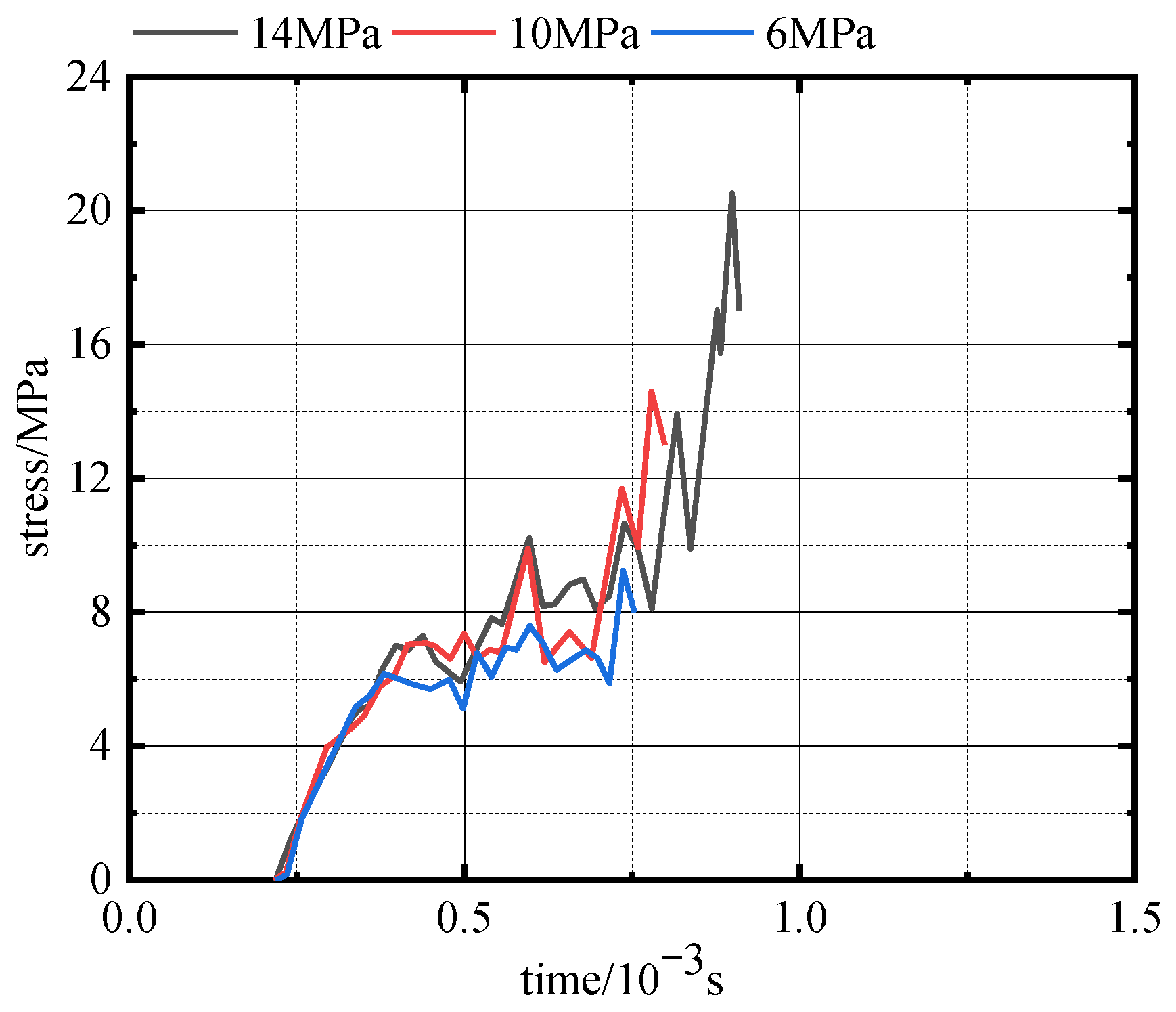
Figure 21 is the damage time series curve of the coal unit under different coal strengths, and Figure 22 is the stress time series curve of the coal unit under different coal strengths. It can be seen that the coal unit can enter the damage accumulation stage quickly when the coal strength is 6 MPa, but it requires a long time to accumulate sufficient damage to reach the complete damage stage. According to Figure 21 and Figure 22, when the coal strength is 14 MPa, the coal unit requires a long time to enter the damage accumulation stage, and achieve complete damage after a short time of damage accumulation. Therefore, it can be concluded that the destruction of coal units with larger strength requires greater stress.
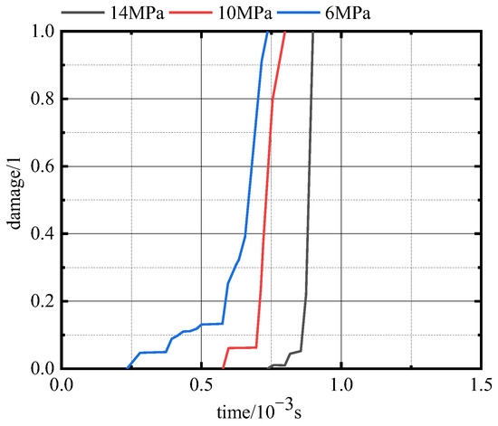
Figure 21.
The damage time series curve of coal units under different coal strengths.

Figure 22.
The stress time series curve of coal units under different coal strengths.
3.4. Coal-Breaking Law of Water Jet Under the Influence of Jet Target Distance
To explore the impact of jet target distance on the coal-crushing effect, the water jet coal-breaking process was simulated according to Simulation Scheme 3 and Scheme 4. Figure 23 shows the depth of coal breaking and the damage distribution of the coal body under different jet target distances at a jet pressure of 32 MPa and a coal strength of 6 MPa.
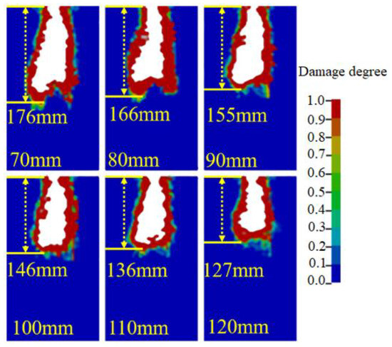
Figure 23.
Damage distribution under different jet target distances.
Figure 24 shows the coal-breaking depth with jet target distance under different jet pressures (the coal strength l is 6 MPa), and Figure 25 shows the coal-breaking depth with jet target distance under different coal strengths (the jet pressure is 36 MPa). It can be concluded that there is a linear decrease in the coal breakage depth with the jet target distance increase.
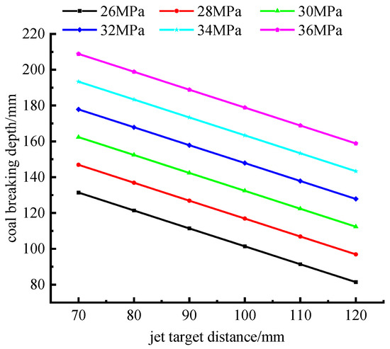
Figure 24.
The variation in coal-breaking depth with jet target distance under different jet pressures.
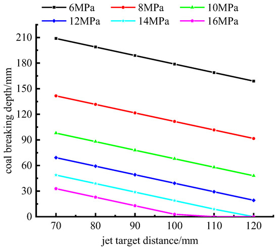
Figure 25.
The variation in coal-breaking depth with jet target distance under different coal strengths.
To explore the impact of jet target distance on the damage and stress fields of the coal body in the coal-breaking process (the jet pressure is 30 MPa and the coal strength is 6 MPa), when the depth of coal breaking reached 70 mm, the analysis tangent PQ is selected, and the damage distribution and stress distribution of the coal body along PQ were plotted. The position of the PQ tangent is shown in Figure 26.
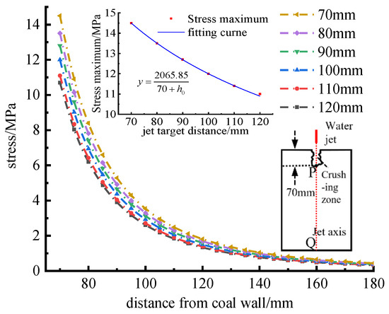
Figure 26.
The stress distribution of coal body on PQ under different jet target distances.
Figure 26 illustrates the stress distribution on PQ under different jet target distances. It can be noticed that the coal body stress decreases exponentially as the distance from the coal wall increases. According to the stress distribution curves of coal under different jet target distances, it is noticed that when the jet reaches the same position, a smaller jet target distance leads to greater stress, while a larger jet target distance leads to a smaller jet impact stress at the same position. By fitting the stress distribution of PQ under different jet target distances, the stress distribution law of coal on the PQ under different jet target distances can be obtained as follows:
where the jet target distance and is the distance between one point in the coal and the coal wall, . According to Formula (17), it can be seen that the stress of the P position is when the jet reaches point P, and then it is attenuated according to the attenuation rate of .
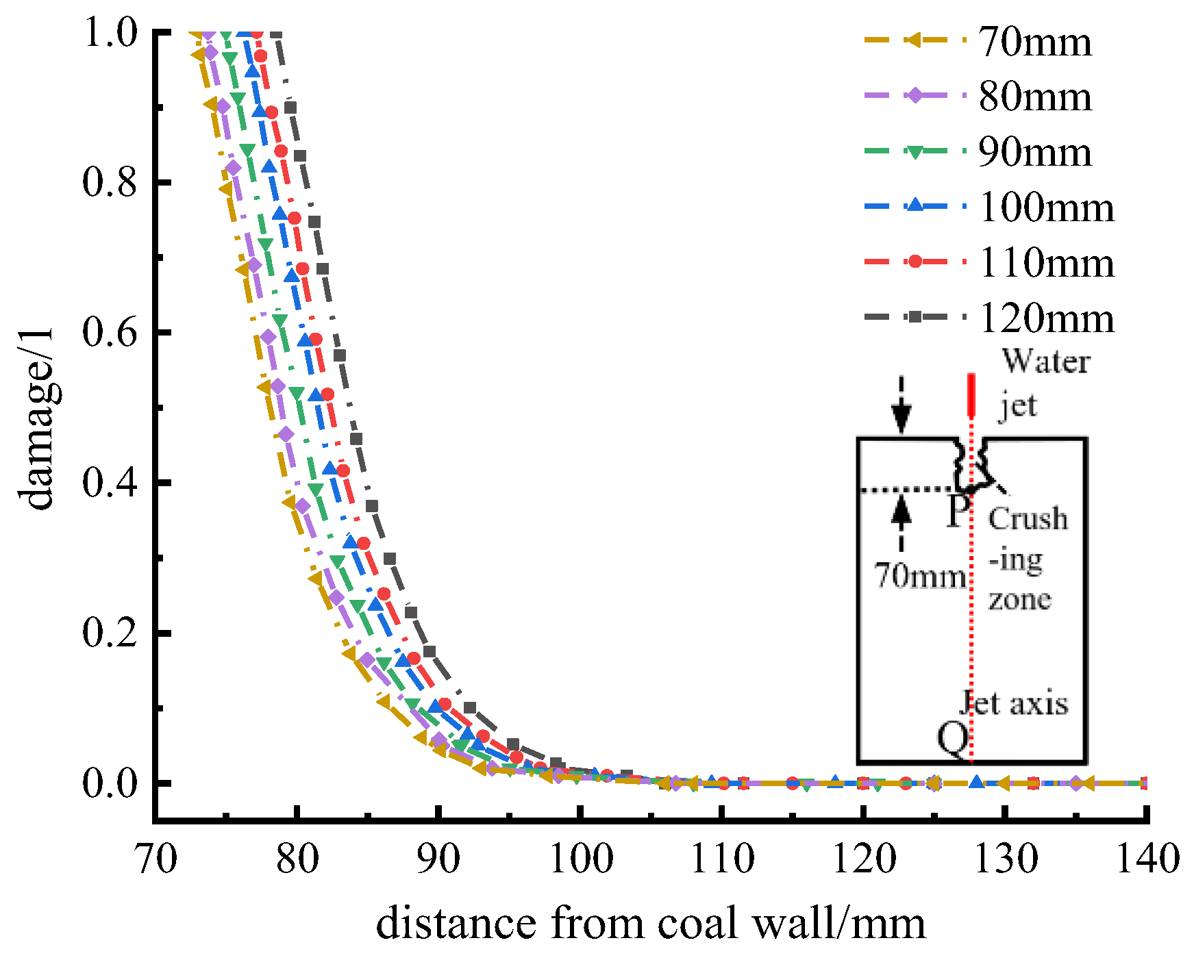
Figure 27 shows the distribution of coal damage on the PQ under different jet target distances, and it is noticed that the coal body damage degree declines exponentially as the distance from the coal wall increases. As the jet target distance decreases, the extent of complete damage to the coal body expands, and the degree of damage at the same position becomes more pronounced. By fitting the damage distribution curve of coal under different jet target distances, it can be concluded that
where is jet target distance; is the distance between one point in the coal and the coal wall, ; and is the distance from the critical position of damage attenuation to the coal wall.
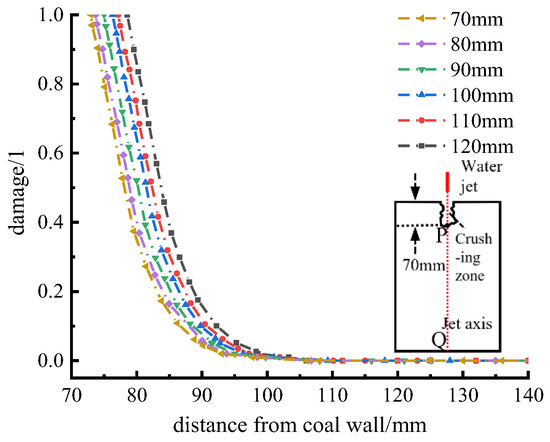
Figure 27.
The damage distribution of coal body on PQ under different jet target distances.
To better understand how the jet target distance affects the damage evolution in coal units (the jet pressure is 30 MPa and the coal strength is 6 MPa), the coal unit (464760#) at 100 mm from the coal wall on the jet axis was selected as the analysis object (Figure 28), the damage time series curve and stress time series curve of the coal unit was plotted.
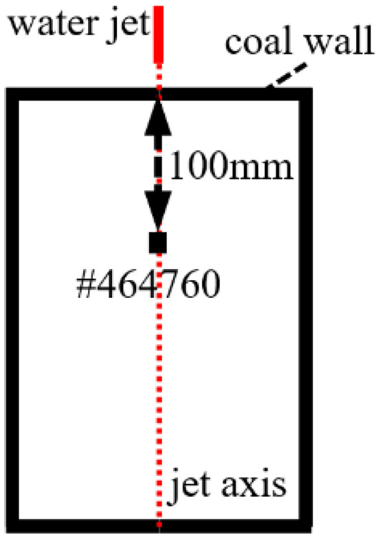
Figure 28.
464760#coal unit location.
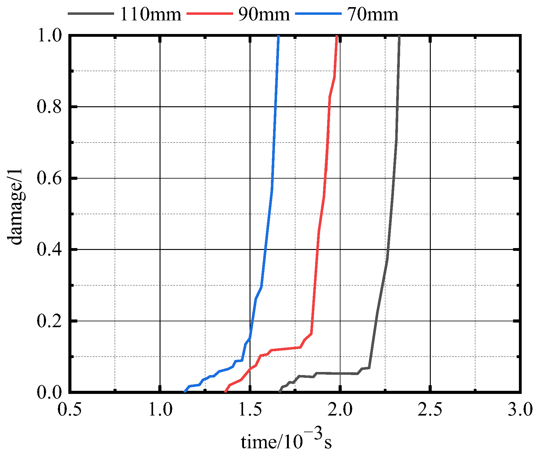
Figure 29 is the damage time series curve of the coal unit, and Figure 30 is the stress time series curve of the coal unit. According to Figure 29 and Figure 30, when the jet target distance is 70 mm, the coal body unit enters the damage accumulation stage earliest and achieves complete damage requiring a short time. Conversely, when the jet target distance is 110 mm, the coal body unit enters the damage accumulation stage latest and requires a long time to achieve complete damage.
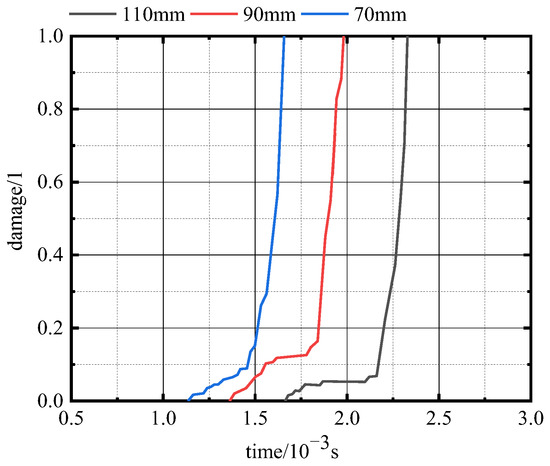
Figure 29.
The damage time series curve of coal unit under different jet target distances.
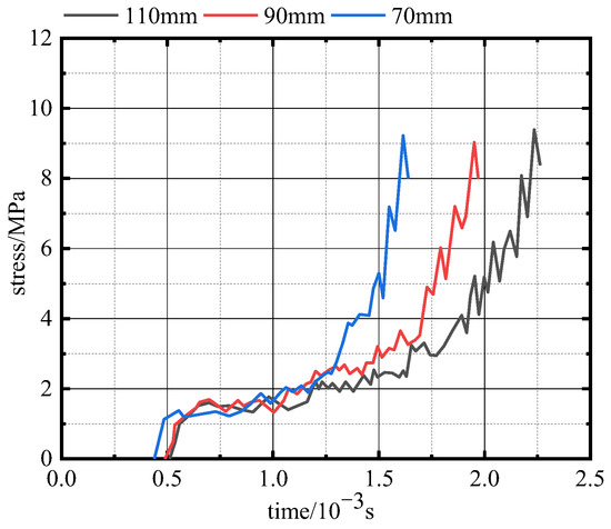
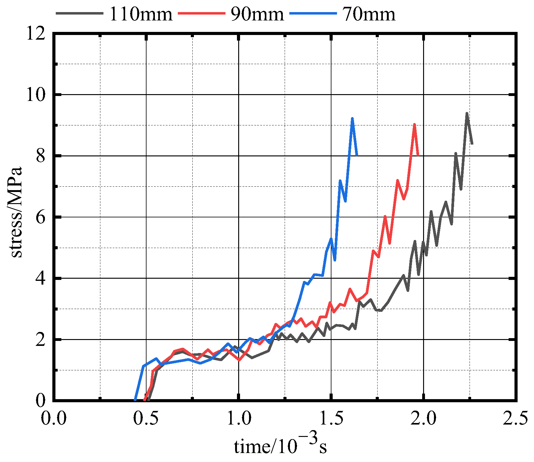
Figure 30.
The stress time series curve of coal unit under different jet target distances.
3.5. Discussion on the Repair Effect of Water Jet and Coal Body Parameters on Gas Extraction Boreholes
Accurately grasping the law of water jet coal-breaking depth is very important for the rational design of water jet coal-breaking process parameters. By studying the comprehensive influence of jet pressure, coal strength, and jet target distance on coal-breaking depth, we can provide a theoretical basis for selecting appropriate water jet equipment and determining the best operating parameters in actual production so as to improve coal-breaking efficiency and reduce energy consumption and cost. The study of stress distribution and damage distribution of coal in the process of water jet breaking coal is helpful for understanding the breaking mechanism of coal bodies. Understanding the stress distribution law and damage distribution law of coal bodies can predict the damage area and damage degree of coal bodies under the action of a water jet, and provide a basis for optimizing the coal-breaking scheme of water jets. According to the numerical simulation and theoretical analysis, the law of coal-breaking depth, stress distribution, and damage distribution under the combined action of these three factors are analyzed and discussed.
1. The depth of coal breaking
The relationship between the depth of coal breaking under the jet pressure, coal strength, and jet target distance is analyzed and fitted. The relationship can be concluded as follows:
where is the jet pressure; is coal strength; and is the jet target distance.
According to Equation (19), a positive linear relationship exists between coal-breaking depth and jet pressure, consistent with previous research results [28]. It can be concluded that the influence of jet pressure on coal-breaking depth is different under different coal strengths. The influence of jet pressure on coal-breaking depth under different coal strengths can be expressed as the slope of the curve of jet pressure and coal-breaking depth, and the slope is . In addition, the coal-breaking depth is negatively correlated with the coal strength and negatively linear with the jet target distance. When , the depth of coal breaking . It can be seen that there is a critical jet pressure under the condition of a certain jet target distance and coal strength. When the jet pressure is greater than the pressure, the coal-breaking depth will be generated. This is because there is a critical value of the stress on the coal body with a certain coal strength. When the stress is greater than the critical value, the coal body starts to break [24].
With the intention of verifying the correctness of Equation (19), When the jet pressures are 26 MPa, 28 MPa, 30 MPa, 32 MPa, 34 MPa, and 36 MPa (The coal body strength is 6 MPa, the jet target distance is 70 mm), a comparison of the simulation results with the calculated results from Equation (19) is shown in Figure 31.
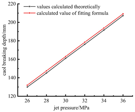
Figure 31.
Comparison of simulated coal-breaking depth and fitting formula calculation results.
Based on Figure 31, it is noticed that the discrepancy between the coal-breaking depth obtained through numerical simulation and that calculated by the fitting formula is quite tiny and remains basically consistent. It can be concluded that it is reasonable to calculate the depth of coal breaking using Equation (19).
According to the simulation results, it can be seen that the influence of jet pressure, coal strength, and jet target distance on the depth of coal breaking is different. To analyze the degree of the influence of coal strength, jet target distance, and jet pressure on the depth of coal breaking, a derivative of jet pressure, coal strength, the derivative of , , and in Equation (19), can be obtained:
Taking into account the engineering background of this article, in the jet pressure , coal strength and the size of and are analyzed; it can be concluded that the value range of is , and the value range of is . Therefore, when the jet pressure and the coal strength . That is, the extent of influence exerted by coal strength, jet pressure, and jet target distance on the depth of coal breakage diminishes successively. From the effect of restoring the borehole diameter of gas extraction, the higher the coal strength is, the more unfavorable it is to the repair of gas extraction boreholes. When the coal strength is large, the type and mode of water jet can be considered in the implementation of water jet repair operations, such as abrasive water jet or pulsed water jet. When the coal strength is small, it is more efficient to increase the depth of coal breaking by increasing the water jet pressure. At the same time, an elevated jet pressure is more beneficial to the repair of gas drainage boreholes. The larger the jet target distance, the more disadvantageous the repair of gas extraction boreholes.
2. Stress distribution
The coal body stress distribution is an important parameter related to the repair effect of extraction boreholes. The study of stress distribution of coal in the process of water jet breaking coal is helpful in understanding the breaking mechanism of coal. Based on the results of theoretical analysis and numerical simulation, the stress distribution of the coal body along the axial direction of the jet can be expressed as follows:
where is the coal stress at position; is the distance from the coal wall at a point on the axis of the jet in the coal body, ; and is the distance for the jet to reach the position to the nozzle.
It can be seen from Equation (23) that when , the stress of coal is at the position of , and then with the increase in x, the coal stress decreases at the decay rate of ; when , the coal body stress is at the position of , and then decays at the decay rate of as x increases. It can be seen that with the deepening of the coal seam, the stress decreases sharply. This is because the propagation of water jet impact stress must constantly overcome the cohesion of the coal [12].
3. Damage distributions
The damage distribution of coal serves as an important indicator for reflecting the extraction borehole repair effect. Coal damage is associated with the stress on the coal body. The degree of coal damage is determined by the coal body’s capacity to resist the impact of water jets. Once the stresses applied to the coal body exceed its capacity to withstand the impact of water jets, the coal body starts to damage. With the stress increases, the damage increases sharply. When the coal body’s stress is greater than its resistance to complete damage, the coal body will be completely damaged. The capacity of a coal body to withstand the impact of water jets is correlated with its strength. According to the theoretical analysis, the critical damage stress when the coal body with different coal strength begins to damage is as follows:
where is the critical stress at the beginning of coal damage and is coal strength. It can be seen that the critical damage stress has a positive linear relationship with the coal strength.
Combined with the stress distribution law and the attenuation law of coal damage, the distribution of coal damage can be expressed as follows:
(1) When , the coal body is located outside the basic section.
where is the distance from the coal wall at a point on the axis of the jet in the coal body, ; is the distance between the jet head position and the jet nozzle; and is the distance from the critical position of damage attenuation to the coal wall. It can be seen that the damage degree of the coal body can reach complete damage within a certain distance from the jet arrival position, and the range of complete damage is .
(2) When , the coal body is located inside the basic section.
where is the distance from the coal wall at a point on the axis of the jet in the coal body, , and is the distance from the critical position of damage attenuation to the coal wall.
Comparing the stress distribution law and damage distribution law of coal bodies, it can be seen that there is a corresponding relationship between the damage degree of coal bodies and stress. The corresponding relationship between the damage degree of coal units and stress under different coal strength conditions is different.
From Equations (25) and (26), it is evident that the extent of the coal damage exhibits an exponential growth with the water jet pressure increase. The extent of coal damage declines exponentially with the distance from the water jet’s arrival position increase. As the coal strength increases, the critical stress at which damage to the coal body begins to occur becomes greater. It can be seen that when other conditions are certain, the position where the coal body damage begins to decay and the rate of damage attenuation is related to the strength of the coal body. The greater the strength of the coal body, the faster the damage attenuation, and the smaller the damage range of the coal body. It can be concluded that under the same jet pressure, when the limited coal-breaking depth is reached, the smaller the coal strength, the greater the range of coal damage. In the process of actual water jet coal-breaking operation, the damage degree and damage range of coal bodies around the borehole caused by the water jet can be calculated according to the law of coal body damage attenuation. At the same time, the scope of damage caused by water jets to the surrounding rock of gas extraction boreholes is limited.
4. Conclusions
A mathematical model of the water jet breaking coal process was established. Subsequently, a calculation model for determining the depth of coal breaking was attained. Through numerical simulation, the coal-crushing depth, the distribution of coal stress, and the damage under the influence of jet pressure, jet target distance, and coal strength were obtained. The impacts of jet pressure, the target distance, and the coal strength on the restoration of gas extraction boreholes are deliberated. The final conclusions are as follows:
(1) The depth of coal breakage increases linearly with the increase in jet pressure. When the coal strength is relatively low, the rate of increase in the depth of coal breaking is more pronounced. The depth of coal breaking decreases in a linear manner with the jet target distance increases. When the coal strength is small, increasing the jet pressure can significantly increase the coal-breaking effect. The relationship model between jet pressure, coal strength, and jet target distance and coal-breaking depth can be used to select more suitable jet pressure parameters.
(2) The relationship model among jet pressure, coal strength, and jet target distance with coal breaking depth was obtained. In terms of their influence degree on coal-breaking depth, it decreases successively for the strength of coal, water jet pressure, and jet target distance.
(3) The stress distribution model and the damage distribution model of coal under the influence of coal strength, jet target distance, and jet pressure were acquired by fitting. Along with the increase in water jet pressure, the coal body stress at the same position becomes greater. Consequently, the range of complete damage to the coal expands, and the coal body at the same position as the coal wall sustains a more severe damage degree. The greater the strength of coal, the faster the attenuation of coal damage. There is a corresponding relationship between the damage degree of coal body unit and the stress.
(4) With the jet pressure getting higher, the stress and the damage degree of the coal body increase correspondingly, and the more favorable the water jet’s restoration efficacy on the gas extraction boreholes is. When the coal strength is higher and the jet target distance is greater, the coal stress becomes smaller and the degree of damage is lower. This situation is less conducive to the repair of gas extraction drill holes. The scope of damage caused by water jet flow to the surrounding rock of gas extraction boreholes is limited.
Author Contributions
G.X.: writing—review and editing, supervision, conceptualization, methodology, project administration, and funding acquisition. S.L.: writing—review and editing, writing—original draft, and methodology. L.S.: writing—review and editing and software. X.L.: writing—review and editing. Y.S.: visualization. H.J.: writing—review and editing. All authors have read and agreed to the published version of the manuscript.
Funding
This work was financially supported by the National Key Research and Development Program of China (2018YFC0807805) and the Natural Science Basic Research Program of Shaanxi (2019JM-072).
Data Availability Statement
The original contributions presented in this study are included in the article. Further inquiries can be directed to the corresponding authors.
Conflicts of Interest
Authors Yongke Shan and Sun Long were employed by the company Xin’an Coal Mine, Henan Dayou Energy Co., Ltd. The remaining authors declare that the research was conducted in the absence of any commercial or financial relationships that could be construed as a potential conflict of interest.
References
- Wang, S.; Geng, J.; Li, P.; Sun, Q.; Fan, Z.; Li, D. Construction of geological guarantee system for green coal mining. Coal Geol. Explor. 2023, 51, 33–43. [Google Scholar] [CrossRef]
- Eshraghi, H.; de Queiroz, A.R.; DeCarolis, J.F. US Energy-Related Greenhouse Gas Emissions in the Absence of Federal Climate Policy. Environ. Sci. Technol. 2018, 52, 9595–9604. [Google Scholar] [CrossRef] [PubMed]
- Xu, C.; Li, H.; Lu, Y.; Lu, J.; Shi, S. Research status of borehole instability characteristics and control technology for gas extraction in soft coal seam. Min. Saf. Environ. Prot. 2022, 49, 131–135. [Google Scholar] [CrossRef]
- Stephenson, T.; Valle, J.E.; Riera-Palou, X. Modeling the Relative GHG Emissions of Conventional and Shale Gas Production. Environ. Sci. Technol. 2011, 45, 10757–10764. [Google Scholar] [CrossRef]
- Li, X.; Zheng, J.; Song, Y.; Guo, D.; Ma, H.; Wang, J. On infiltration enhancement mechanism of shaped charge blasting in high gas and low permeability coal seam. Explos. Shock Waves 2023, 43, 158–170. [Google Scholar] [CrossRef]
- Merzlyakov, V.G.; Baftalovsky, V.E. On using hydraulic technology for mechanization of mining operations. Min. Equip. Electromech. 2010, 6, 2–6. [Google Scholar]
- Sun, X.; Ni, H.; Wang, R.; Shen, Z.; Zhao, M. Characteristic study on supercritical carbon dioxide impinging jet: Calculation and stagnation properties analysis. J. Pet. Sci. Eng. 2018, 162, 532–538. [Google Scholar] [CrossRef]
- Momber, A.W. The response of geo-materials to high-speed liquid drop impact. Int. J. Impact Eng. 2016, 89, 83–101. [Google Scholar] [CrossRef]
- Xue, Y.; Si, H.; Yang, Z.; Xu, D. Microscopic damage field in coal induced by water jets. J. Loss Prev. Process Ind. 2018, 56, 300–315. [Google Scholar] [CrossRef]
- Xue, Y.; Si, H.; Chen, G. The fragmentation mechanism of coal impacted by water jets and abrasive jets. Powder Technol. 2020, 361, 849–859. [Google Scholar] [CrossRef]
- Gao, Y.; Xiang, X.; Guo, X.; Han, P. Characteristics and mechanism of coal and rock breaking with water jet impact in drill hole. J. Vib. Shock 2022, 41, 51–59+85. [Google Scholar] [CrossRef]
- Gao, Y.; Han, P.; Wang, F.; Cao, J.; Zhang, S. Study on the Characteristics of Water Jet Breaking Coal Rock in a Drilling Hole. Sustainability 2022, 14, 8258. [Google Scholar] [CrossRef]
- Liu, X.; Liu, S.; Ji, H. Numerical research on rock breaking performance of water jet based on SPH. Powder Technol. 2015, 286, 181–192. [Google Scholar] [CrossRef]
- Jiang, H.; Liu, Z.; Gao, K. Numerical simulation on rock fragmentation by discontinuous water-jet using coupled SPH/FEA method. Powder Technol. 2017, 312, 248–259. [Google Scholar] [CrossRef]
- Liu, M.; Zhao, W.; Liu, Y.; Wei, J. Research and application of hydraulic flushing borehole to quickly eliminate outburst. Coal Sci. Technol. 2010, 38, 58–61. [Google Scholar] [CrossRef]
- Wang, Z.; Fan, Y.; Li, S. Application of Borehole Hydraulic Flushing Technology to Soft and Outburst Seam with Low Permeability. Coal Sci. Technol. 2012, 40, 52–55. [Google Scholar] [CrossRef]
- Hao, C.; Chen, X.; Liu, Q. Numerical simulation of coal breaking characteristics by continuous water jet based on ALE algorithm. Saf. Coal Mines 2024, 55, 14–21. [Google Scholar] [CrossRef]
- Pan, Y.; Yang, F.; Zhang, Z.; Ma, H. Numerical simulation of coal rock fragmentation characteristics under interrupted pulse water jet. J. Vib. Shock 2021, 40, 283. [Google Scholar] [CrossRef]
- Zhang, J.; Wei, L.; Zhang, Z.; Li, T.; Yao, B. Influence of Nozzle Structure Based on CFD on Back-propelling Characteristics of High-pressure Water Jet. Chin. Hydraul. Pneum. 2021, 45, 102–107. [Google Scholar] [CrossRef]
- Mi, J.; Huang, F.; Li, S.; Wang, R.; Li, D. Numerical simulation of rock breaking by rear-mixed abrasive water jet based on an SPH-FEM coupling algorithm. J. Vib. Shock 2021, 40, 132–139. [Google Scholar] [CrossRef]
- Xiao, S.; Ren, Q.; Cheng, Y.; Zhao, H.; Cao, S.; Zhang, L.; Chen, B.; Meng, X. Damage and fracture characteristics of rocks with different structures under high-velocity water jet impact. Eng. Fract. Mech. 2021, 256, 107961. [Google Scholar] [CrossRef]
- Xu, G.; Meng, Z.; Liu, J.; Liu, X. Research and application of water jet on drilling expansion repair and permeability enhancement technology in gas extraction drilling. Coal Sci. Technol. 2025, 2, 1–13. [Google Scholar]
- Ge, Z.; Mei, X.; Jia, Y. Influence radius of slotted borehole drainage by high pressure water jet. J. Min. Saf. Eng. 2014, 31, 657–664. [Google Scholar] [CrossRef]
- Mu, Z.; Wu, Y. Crushing strength of the coal agaist high pressure water penetration. Chin. J. Appl. Mech. 2013, 30, 451–456+481–482. [Google Scholar] [CrossRef]
- Lin, X.; Lu, Y.; Tang, J.; Ao, X.; Zhang, L. Numerical simulation of abrasive water jet breaking rock with SPH-FEM coupling algorithm. J. Vib. Shock 2014, 33, 170–176. [Google Scholar] [CrossRef]
- Xiao, S.; Qin, H.; Zhang, W.; Ren, Q.; Xiao, J.; Li, W.; Cheng, Y. On the concrete breakage by pulsed water jet impact: Fracture characteristic, stress and damage evolution laws. Case Stud. Constr. Mater. 2023, 19, e02634. [Google Scholar] [CrossRef]
- Holmquist, T.J.; Johnson, G.A. A computational constitutive model for glass subjected to large strains, high strain rates and high pressures. J. Appl. Mech. 2011, 78, 051003. [Google Scholar] [CrossRef]
- Ge, Z.; Wang, L.; Wang, M. Rock-Breaking Properties Under the Rotatory Impact of Water Jets in Water Jet Drilling. Appl. Sci. 2019, 9, 5417. [Google Scholar] [CrossRef]


Disclaimer/Publisher’s Note: The statements, opinions and data contained in all publications are solely those of the individual author(s) and contributor(s) and not of MDPI and/or the editor(s). MDPI and/or the editor(s) disclaim responsibility for any injury to people or property resulting from any ideas, methods, instructions or products referred to in the content. |
© 2025 by the authors. Licensee MDPI, Basel, Switzerland. This article is an open access article distributed under the terms and conditions of the Creative Commons Attribution (CC BY) license (https://creativecommons.org/licenses/by/4.0/).