Article

Research on the Testing Method for the Rheological Properties of Large-Particle Gangue Filling Slurry

1
School of Energy and Mining Engineering, China University of Mining and Technology (Beijing), Beijing 100083, China
2
School of Mining and Coal, Inner Mongolia University of Science and Technology, Baotou 014010, China
3
School of Mechanics and Civil Engineering, China University of Mining and Technology (Beijing), Beijing 100083, China
*
Author to whom correspondence should be addressed.
Processes 2025, 13(3), 789; https://doi.org/10.3390/pr13030789
Submission received: 4 February 2025 / Revised: 6 March 2025 / Accepted: 7 March 2025 / Published: 8 March 2025

Abstract

:
Coal mine gangue cementation filling technology has increasingly become an effective and major means of dealing with “coal mining under buildings, railways, and bodies of water” and other complex hard-to-mine coal seams; but also, an important part of a large number of treatments of coal gangue stockpiled on the ground is to realize the green mining of coal mines. Coal mine cement filling often contains gangue particles with particle sizes larger than 15 mm; however, the viscometer and rheometer currently used at home and abroad are unable to accurately measure the rheological parameters of the slurry containing large-particle-sized gangue. In order to accurately measure the rheological parameters of slurry containing large-sized gangue particles combined with the site filling materials, the torque values obtained on the mixing blades at different speeds were generated by the combined action of the slurry between the blade side edge and the mixing drum wall, as well as the slurry between the blade lower edge and the mixing drum bottom. A new type of gangue slurry rheometer was developed. The new type of gangue slurry rheometer mainly included components such as the power system, sensing system, mechanical system, and other auxiliary units. Finally, using Fluent software ANSYS2023 to numerically simulate the fluidity of the slurry under the same conditions, the results obtained after the calculation and the test results showed that the error was within a reasonable range, indicating the correctness of the test principles of the new gangue slurry rheometer and the effectiveness of the instrument. This research offers new insights for accurately measuring the rheological parameters of particles with large sizes.

1. Introduction

The development and utilization of mineral resources have greatly promoted the rapid development of human economy, society, and the progress of social civilization, and will continue to be a source of human development in the future [1,2,3,4]. With the continuous development of mineral resources, the number, scale, and depth of mining operations continue to increase [5,6,7,8,9].
Long-term large-scale and continuous mining has led to the depletion of mineral resources with good storage conditions [10]. The recovery and utilization of complex and difficult to mine coal seams, “coal mining under buildings, railways, and bodies of water”, roadway coal pillars, and corner coal, as well as the re-mining of residual coal under other conditions, have gradually entered people’s vision [11]. On the other hand, as the largest industrial solid waste currently stored in China, the massive storage and discharge of coal gangue not only occupies a large amount of land, but its unique physical and chemical properties can also pollute soil and water bodies. At the same time, the spontaneous combustion of gangue mountains can produce a large amount of toxic and harmful gases, pollute the atmosphere, and have a great impact on the ecosystem around the mine [12,13,14]. However, the single utilization method of gangue, its low product added value, and small disposal and utilization capacity and scale cannot meet China’s practical requirements for ecological environmental protection, pollution reduction, and carbon reduction under the “dual carbon” goal. There is an urgent need for effective integrated and systematic action plans to solve these fundamental problems. From the perspective of coal resource recovery and environmental protection, using gangue filling coal mining technology to solve the above special coal mining problems is an effective method [15].
Compared with traditional low-concentration water sand filling, high-concentration cemented filling coal mining technology (such as paste and paste-like filling) has the advantages of a high slurry concentration [16,17,18,19,20], no need for dehydration (or only a small amount of dehydration), the good integrity of the filling body, high strength [21], a significant roof control effect, and a good underground working environment. It has gradually been applied in coal mine goaf treatment in the past decade [22,23,24]. Currently, research on high-concentration cemented filling coal mining technology in coal mines mainly focuses on the development and application of filling coal mining technology and filling systems, as well as the mechanical properties of filling materials and their interaction mechanisms with the surrounding rocks [25,26,27,28,29,30,31]. There is relatively little research on the flow performance and pipeline transportation characteristics of gangue filling slurry [32].
Unlike the tailing filling aggregates used in metal mines, the gangue particles used in coal mine cemented filling have larger particle sizes, some of which can reach 15 mm or even larger. Traditional methods such as NXS-11A rotational viscometer and RheolabQC rheometer cannot accurately measure gangue, as due to their small measurement space, large-sized gangue particles cannot be placed inside. On the other hand, when measuring high concentration slurries containing large-sized gangue particles, the mixing element is prone to slipping due to slip effects, making it difficult to accurately test the rheological parameters of this type of slurry. Based on the above reasons, the author has developed a new type of gangue slurry rheometer suitable for measuring large-sized gangue particles from the perspective of the testing process and the principle of the viscometer for slurry. The improvement in the testing accuracy lays the foundation for the smooth pipeline transportation of coal mine gangue filling slurry.

2. Structure and Working Principle of a New Type of Gangue Slurry Rheometer

2.1. Structure of a New Type of Gangue Slurry Rheometer

In order to adapt to the smooth flow of large-sized gangue particles in the mixing drum, generate accurate shear torque, and improve the automation level and data processing accuracy of slurry testing, a new type of gangue slurry rheometer has been developed. Its structural schematic diagram is shown in Figure 1.
After assembling the various components, the new type of gangue slurry rheometer obtained is shown in Figure 2.

2.2. Working Principle of a New Type of Gangue Slurry Rheometer

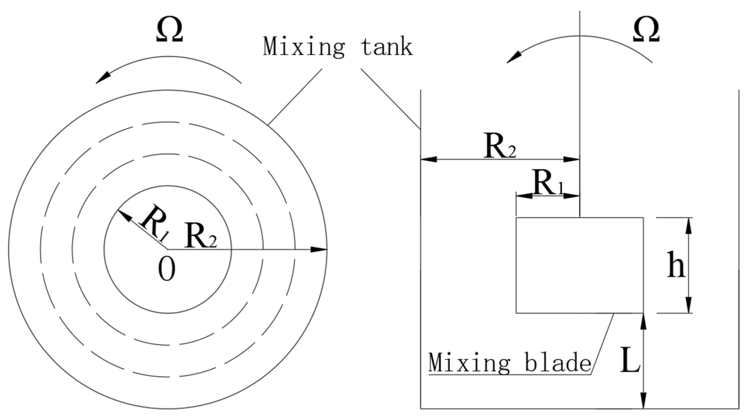
The new type of gangue slurry rheometer adopts a cross-blade type of mixing element. When the rheometer works, the mixing drum is fixed, and the blades are vertically placed into the slurry along the center of the mixing drum. The rotating blades drive the slurry in the drum to make a circular motion, and the slurry is layered due to the combined action of shear stress and friction force [33,34,35]. During this process, the slurry obstructs the stirring blades and generates torque. The received electrical signal is converted into the corresponding torque value by the torque sensor on the stirring rod, and different torque values can be obtained at different speeds. A functional relationship is established between the obtained different torque values and rotational speeds, and finally, the yield stress and viscosity of the tested slurry are calculated. The mixing system and its related dimensions are shown in Figure 3.
When the rheometer is working, the shear deformation rate of the slurry at any point between the stirring blade and the stirring drum wall can be expressed as
γ ˙ = d γ dt = r d ω dr
In Formula (1), γ ˙ is shear rate; r is the distance between any point of the slurry between the blade and the mixing drum wall and the mixing center, m; dω is the rotational angular velocity of the slurry at any point between the blade and the mixing drum wall; and dr is the width of the slurry at any point between the blade and the mixing drum wall, m.
Numerous experiments and studies have shown that as a high concentration fluid, the rheological properties of gangue filling slurry can be expressed using the Bingham model [12]. Therefore, the relationship between shear stress and shear rate can be expressed as:
τ = τ 0 + η γ ˙
In this formula, τ is shear stress, Pa; τ0 is the yield stress; and η is viscosity.
Substituting Equation (1) into Equation (2) yields the following:
τ = τ 0 + η r d ω dr
At this point, the micro torque generated by the slurry at any point between the mixing blade and the inner wall of the mixing drum can be expressed as:
M 1 = 2 π r h τ r = 2 π r 2 h ( τ 0 + η r d ω dr )
Integral to the above equation:
0 Ω d ω = R 1 R 2 M 1 2 π h η r 3 τ 0 η r d r
Ω = M 1 R 2 2 R 1 2 4 π h η R 1 2 R 2 2 τ 0 η ln R 2 R 1
From Equation (6), it can be concluded that:
M 1 = 4 π h R 1 2 R 2 2 R 2 2 R 1 2 η Ω + 4 π h R 1 2 R 2 2 R 2 2 R 1 2 ln R 2 R 1 τ 0
Two parameters are defined:
k 1 = 4 π h R 1 2 R 2 2 R 2 2 R 1 2 k 2 = 4 π h R 1 2 R 2 2 R 2 2 R 1 2 ln R 2 R 1
According to Equation (8):
M 1 = k 1 η Ω + k 2 τ 0
From the above equation, it can be seen that the two parameters k1 and k2 are only related to the size of the rheometer stirring blades and stirring drum. For a given testing instrument, these two parameters are constant values.
When measuring the rheological parameters of fine-grained mixture slurry using a coaxial cylindrical viscometer, the concave and convex settings at the upper and lower ends of the measuring inner cylinder allow a small amount of the measured slurry to overflow, while the convex setting at the lower end seals some air in the space when the measured slurry is placed in the measuring inner cylinder, forming an air cushion. At this time, both the upper and lower ends have no shear effect on the measured slurry, thereby reducing and eliminating the hindering effect of the slurry at the upper and lower ends on the measuring inner cylinder, so that the measured torque value is entirely generated by the slurry in the side slit [36].
However, for measuring the new type of gangue slurry rheometer containing the large-particle-sized gangue filling slurry, the stirring element is a rotatable blade. When it is vertically placed into the measured slurry, the influence of the end of the slurry on the torque value obtained by the blade cannot be eliminated. To achieve this, the first step is to design the blade to be immersed in the measured slurry, with its upper edge tangent to the slurry level, in order to minimize and eliminate the effect of the upper end of the stirring blade. At this point, we only need to consider and calculate the torque generated by the slurry between the lower edge of the blade and the bottom of the slurry storage cylinder on the stirring blade.
The flow behavior of the slurry at the lower end is also caused by the rotation of the mixing blade. The distance between any point on the lower edge of the mixing blade and the mixing center is r, and there is also a velocity gradient due to the frictional force. The movement speed of the slurry decreases layer-by-layer from top-to-bottom until the bottom of the mixing drum reaches 0. Therefore, it can be regarded as a flow model between flat plates, as shown in Figure 4.
Assuming that the distance between the lower part of the mixing blade and the mixing center is r and the width is dr, a section of slurry moves uniformly in a circular motion around the mixing center at a certain speed, and the bottom of the mixing drum is considered as a stationary plate. The shear rate of the end slurry is expressed as:
γ ˙ = Ω r L
The corresponding shear stress is:
τ = τ 0 + η Ω r L
The micro torque generated by the slurry at this point is:
d M 2 = τ 0 + η Ω r L 2 π r 2 d r
The integral to Equation (12) is:
0 M d M 2 = 0 R 1 τ 0 + η Ω r L 2 π r 2 d r
The additional torque of the end slurry is:
M 2 = π R 1 4 2 L η Ω + 2 π R 1 3 3 τ 0
Two parameters are defined equally:
k 3 = π R 1 4 2 L k 4 = 2 π R 1 3 3
M 2 = k 3 η Ω + k 4 τ 0
As can be seen from the above equation, K1 and k2 are still two parameters that are only related to the size of the rheometer stirring blades and stirring drum, and are also constant values for a given testing instrument.
Therefore, the shear torque obtained when testing the rheological parameters of the new gangue slurry rheometer should be:
M = M 1 + M 2 = k 1 + k 3 η Ω + k 2 + k 4 τ 0
By adjusting the rotational speed of the stirring blades to obtain their corresponding different torque values, multiple sets of recorded data are analyzed through regression to obtain a linear function. The ratio of the intercept of the curve on the shear torque axis to (k2 + k4) is the yield stress of the tested slurry, and the ratio of the curve slope to (k1 + k3) is the viscosity of the tested slurry:
τ 0 = M 0 k 2 + k 4 η = k k 1 + k 3
In the formula, M0 is the intercept of the curve on the torque axis, and N·m;k is the slope of the curve.
According to the size of the mixing system, it can be calculated that:
k 1 + k 3 = 0.000189477 k 2 + k 4 = 0 . 000181156

3. New Type of Gangue Slurry Rheometer for Testing Rheological Parameters of Slurry

3.1. Preparation of Gangue Filling Slurry

This article selected the actual filling gangue used in the Linxi mine of Kailuan Mining, with a maximum particle size of 15 mm, and the nearby power plant produced fly ash, local PO42.5 ordinary Portland cement, and urban tap water. The specific content is shown in Table 1.
First, all the dry ingredients were poured into a large beaker according to the ratio, mixed well with a spatula, then stirred with water, and finally poured into the test mixing cylinder for testing.

3.2. Test Data Analysis of Gangue Slurry at Different Rotational Speeds

The torques of the gangue slurry at different speeds obtained through testing are shown in Table 2.
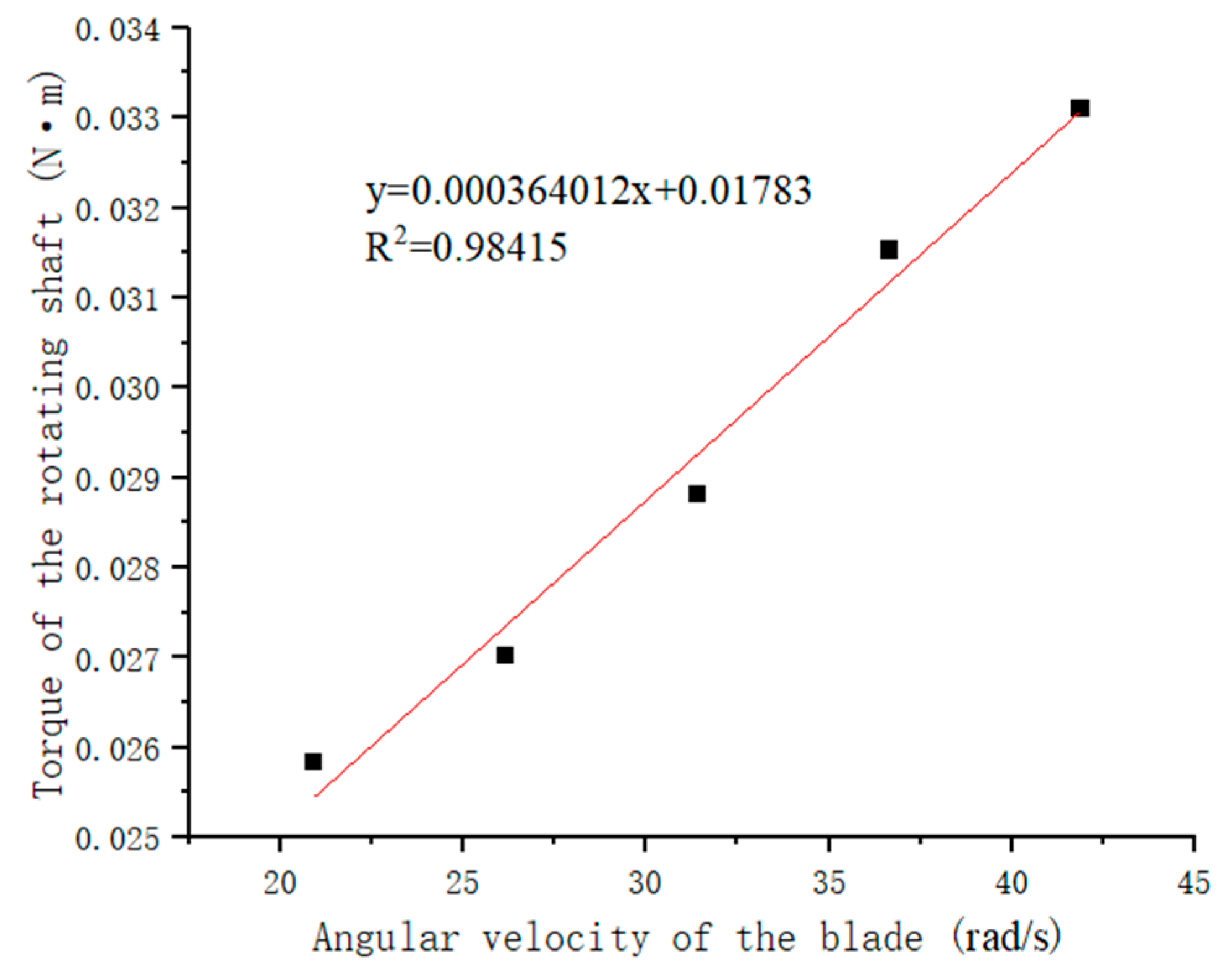
Figure 5 shows the expression of the curve obtained by fitting the torque values obtained at different rotational angular speeds of the blade, thus obtaining the slope of the curve and its intercept on the torque axis. The yield stress and viscosity values of the tested slurry can be obtained from Formula (18), as follows:
τ 0 = 0.01748 0.000181156 = 96.49 P a η = 0 . 000357188 0.000189477 = 1.89 P a · s

4. Numerical Simulation of the Testing Process of a New Type of Gangue Slurry Rheometer

Using Fluent numerical simulation software ANSYS2023, a three-dimensional model of the mixing system for the gangue slurry is established to simulate the velocity and pressure distribution of the cross-shaped mixing blades at different gangue slurry speeds, and the corresponding measured torques are obtained.

4.1. Model Establishment and Grid Division

The mixing element of the new type of gangue slurry rheometer consists of two rectangular thin sheets of identical size that pass through the axis and are perpendicular to each other, as shown in Figure 6. The blade size is 40 mm long, 30 mm high, and 2 mm thick, and the transmission connecting rod is 60 mm long. The mixing drum is a standard cylinder with a diameter and height of 100 mm. The three-dimensional model of the mixing blades and drum is shown in Figure 7.
A three-dimensional model of the mixing blade and mixing drum are established, and sliding mesh technology is used to divide the model calculation domain into two nested concentric cylinders. The data continuously transitioned and interacted through the Match Interface between the two cylinders.
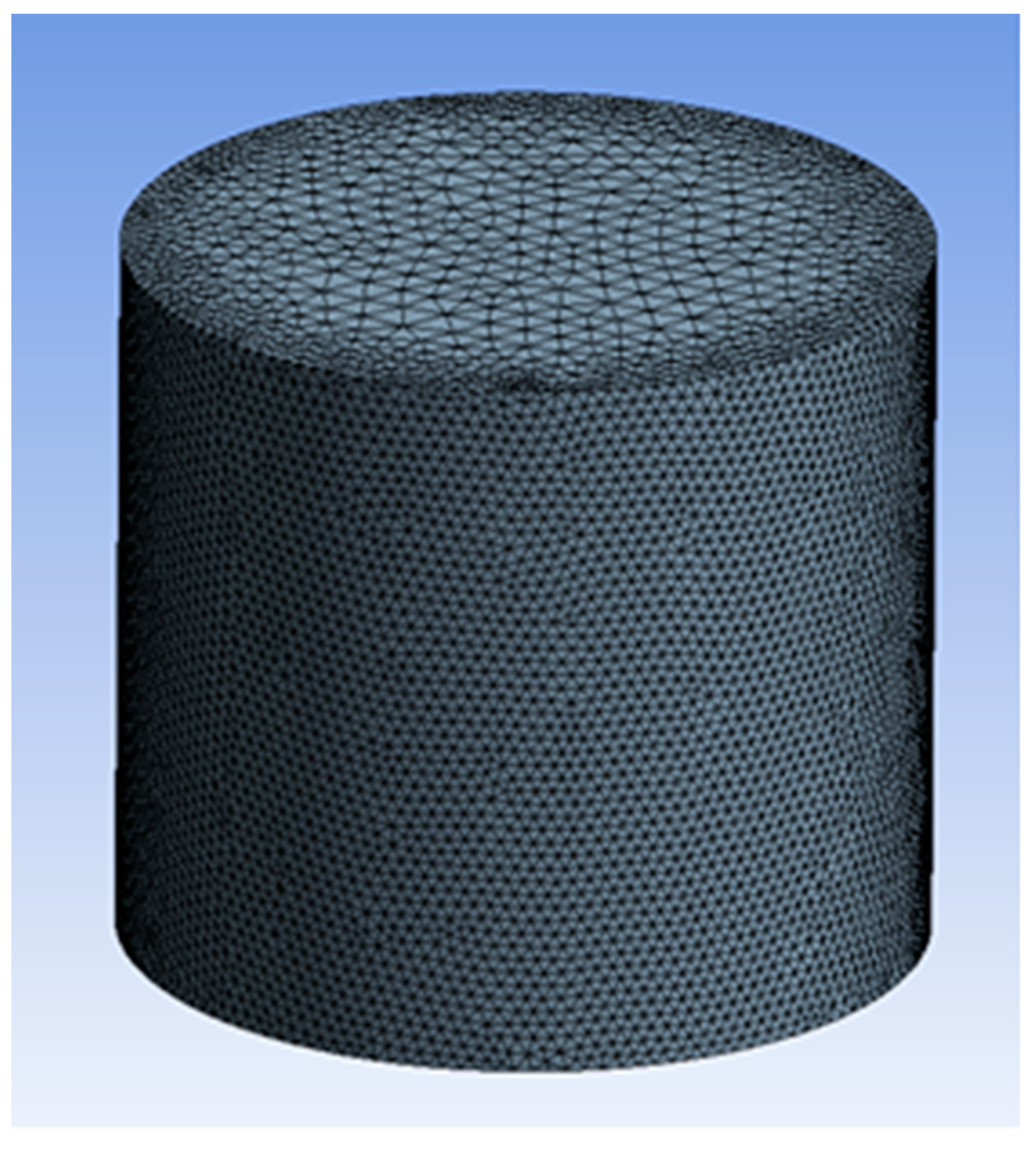
In order to describe the flow behavior of the slurry at the blade rotation in detail, using a tetrahedral mesh partitioning model, as shown in Figure 8, the mesh refinement at the blade is set to 0.02 mm, and the rest is set to 0.08 mm. Therefore, a total of 275,584 tetrahedral mesh elements are partitioned.

4.2. Parameter Setting of Slurry Model

The numerical simulation of the flow behavior of gangue slurry requires the physical parameters of the measured slurry, including density, viscosity, and yield stress, as shown in Table 3.
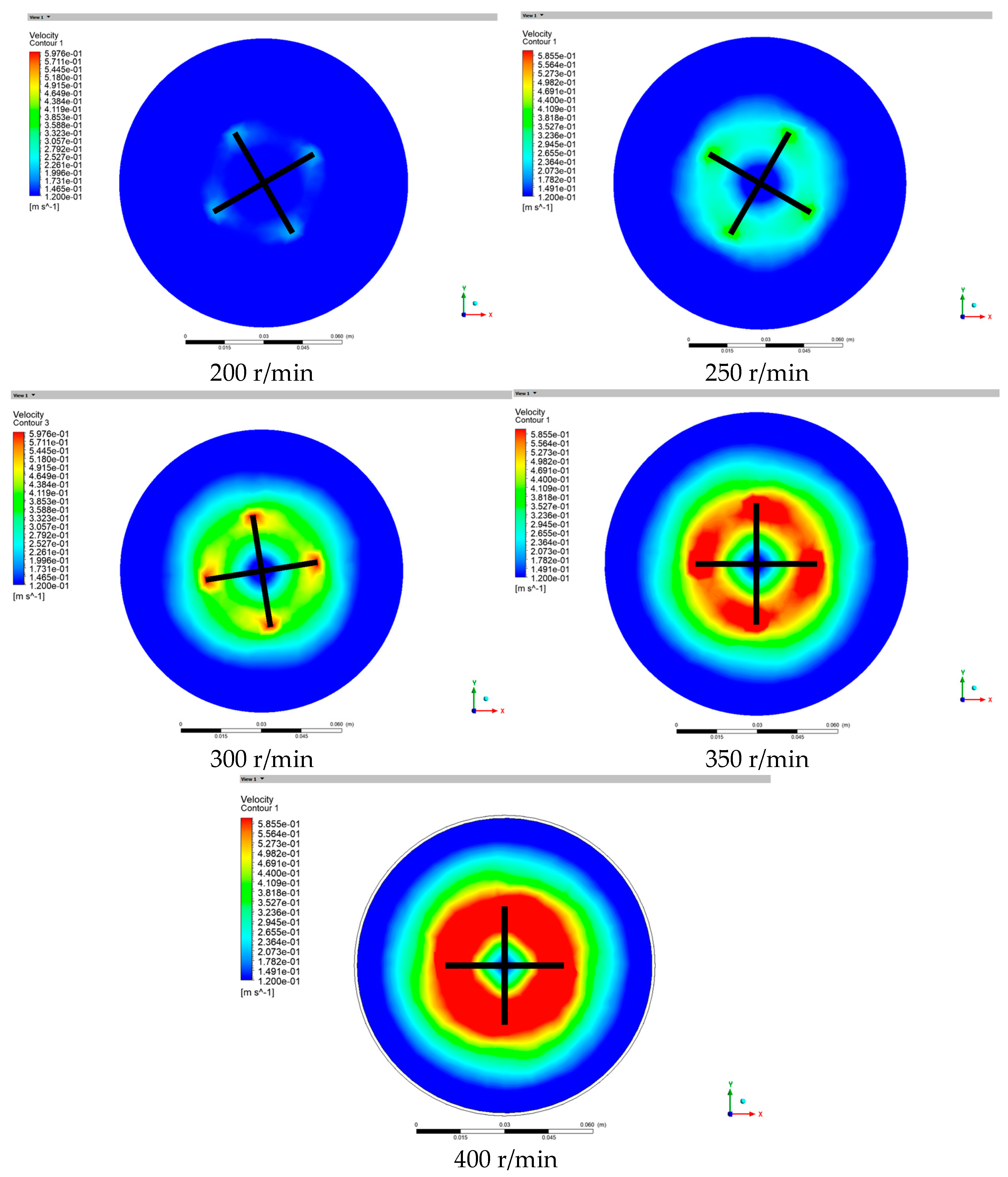
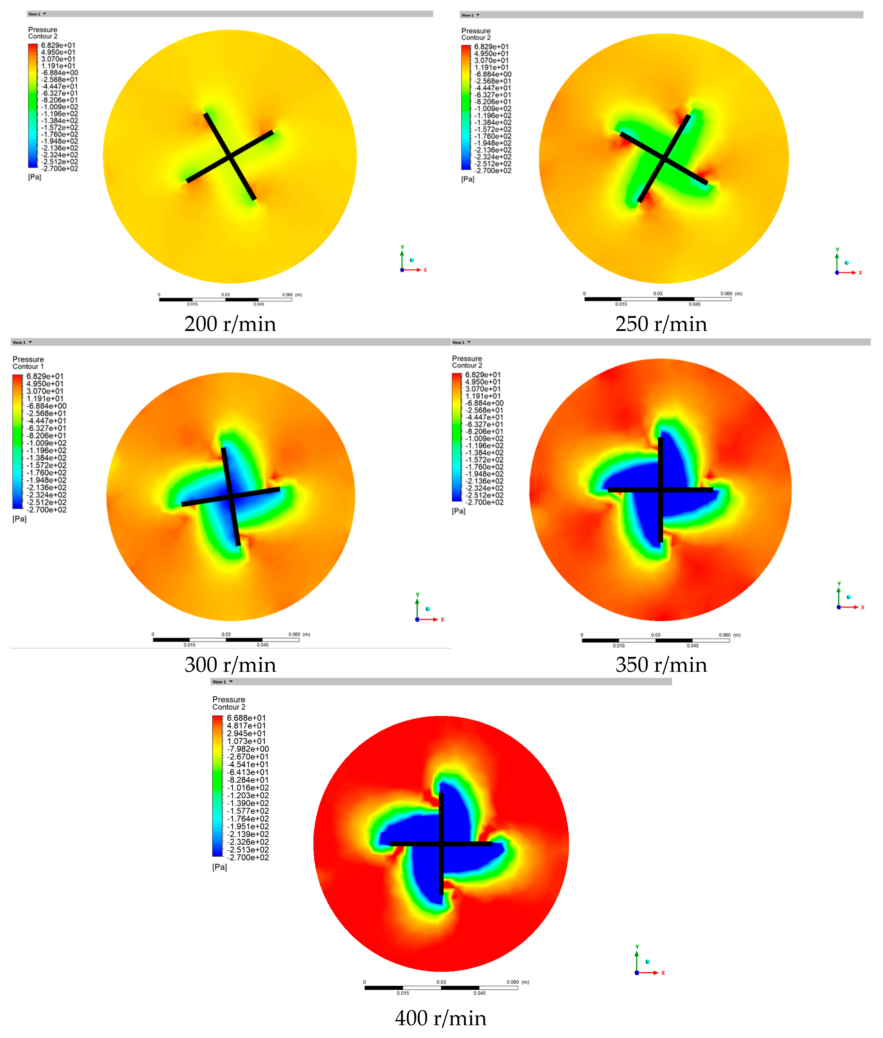
The constitutive equation of the Herschel–Bulkley model is used to define the gangue slurry. During initialization, the upper edge of the blade is set to coincide with the slurry level, and the lower edge of the blade is 2.5 cm away from the bottom of the mixing drum. When the blade speeds are 200 r/min, 250 r/min, 300 r/min, 350 r/min, and 400 r/min, the flow behavior of the slurry at a cross-section 1.5 cm below the slurry level, where the lower edge of the mixing blade is located, is observed, and the torque obtained by the mixing blade is detected.

4.3. Observation of Velocity Distribution of Cross-Sectional Slurry at Different Rotational Speeds

Figure 9 shows the velocity distribution cloud map of the slurry observed at different speeds. It can be seen from the figure that the flow velocity of the slurry at the edge of the stirring blade is the fastest on the observed section, gradually decreases as it moves away from the blade edge, and reaches zero at a certain distance from the blade edge. This is because the slurry is subjected to the thrust generated by the rotation of the blades, causing the slurry near the edge of the blades to have the same rotational speed as the stirring blades. However, due to the frictional resistance inside the slurry, the speed gradually decreases to zero as it moves away from the blades, showing a gradient change pattern. As the rotational speed of the blade increases, the velocity of the slurry near the edge of the blade also increases. At the same time, the range of the maximum velocity gradually increases and extends away from the edge of the blade. Therefore, the area of minimum velocity gradually decreases.

4.4. Pressure Distribution of Observed Cross-Sections at Different Rotational Speeds

Figure 10 shows the pressure distribution cloud map of the observed cross-section of slurry at different speeds, which reflects the force situation of the slurry during the mixing process on the observed cross-section. From the figure, it can be seen that the stirring blades rotate counterclockwise, and the slurry located in front of the blade movement on the observation section is subjected to compressive stress, as shown in the red area in the figure. The slurry located behind the blade movement is subjected to tensile stress, as shown in the blue area in the figure. The maximum stress occurs a little further in from the edge of the mixing blades. As the blade speed increases, the range and magnitude of the compressive stress on the front of the blade movement gradually increase, and stress minima occur at the blade crossings immediately adjacent to the blades. At the same time, the range and magnitude of tensile stress on the back of the blade movement also gradually increase and eventually become integrated, closely adhering to the back of the blade movement direction. The difference between the two stresses gradually increases with the rotational speed and eventually forms a clear boundary.

4.5. Torque of Stirring Blades at Different Speeds

During the testing process of the new type of gangue slurry rheometer using numerical simulation, the torque obtained by the stirring blades over time at different speeds can be obtained through a monitor, as shown in Figure 11. The torque on the stirring blades gradually increases within a short time range and eventually stabilizes before no further changes occur.
The torque values on the stirring blades at different speeds are shown in Table 4.
After conducting a regression analysis on the blade angular velocity and torque in the table above, the linear functions of the two were obtained, as shown in Figure 12.
The yield stress and viscosity of the simulated slurry can be obtained from Figure 12 and Formula (18), as follows:
τ 0 = 0.01783 0.000181156 = 98.42 P a η = 0 . 000364012 0.000189477 = 1.92 P a · s
From Table 5, it can be seen that the yield stress and viscosity of the slurry obtained from numerical simulation are 98.42 Pa and 1.92 Pa·s, respectively, while the measured yield stress and viscosity of the slurry under the same conditions are 96.49 Pa and 1.89 Pa·s, respectively; the differences are 1.93 and 0.03, respectively, with errors of 2% and 1.59%, respectively. It can be seen that the errors are within a reasonable range, indicating the effectiveness of the testing principle of the new gangue slurry rheometer.

5. Conclusions

This paper analyzes the issue of being unable to obtain accurate rheological parameter test values in current coal mine gangue filling slurry due to the presence of large-sized particles. The specific research findings are as follows:
(1)
Due to the current inability to accurately measure the rheological parameters of slurry containing large-sized gangue particles, a new type of gangue slurry rheometer has been developed. The working principle of the newly developed gangue slurry rheometer is to obtain the torque of the stirring blades at different speeds and calculate the rheological parameters of the slurry. The torque is generated by the combined action of the slurry between the blade side edge and the cylinder wall, and the slurry between the blade lower edge and the cylinder bottom.
(2)
Testing is conducted on a slurry containing a 76% concentration of large-sized gangue material, and the torque on the stirring blades is obtained at a speed of 200–400 r/min. As the speed increases, the torque values obtained on the blades gradually increase. The yield stress and viscosity are calculated to be 96.49 and 1.89, respectively.
(3)
Fluent is used to simulate the flow behavior of gangue slurry under the same conditions, and it is found that the maximum velocity of the slurry appears at the edge of the mixing blade and decreases towards the direction away from the blade edge, forming a velocity gradient. The front of the blade’s direction displays compressive stress, while the rear displays tensile stress. As the rotational speed increases, the difference between the two stresses gradually increases and a clear boundary appears. Based on the torque values obtained on the blades at different speeds, through regression analysis and calculation, the yield stress and viscosity of the slurry are found to be 98.42 and 1.92, respectively, with errors of 2% and 1.59%, respectively. This demonstrates the effectiveness of the new gangue slurry rheometer test.
(4)
This study provides a basis for the accurate measurement of the rheological parameters of large particle sizes, ensuring the smooth transportation of high-concentration gangue slurry in pipelines and providing a reference for the design of filling processes and filling systems.

Author Contributions

Conceptualization, X.D. and Y.H. (Yucheng Huang); methodology, Y.H. (Yuxin Hao); software, L.Z.; validation, X.D. and Y.H. (Yucheng Huang); formal analysis, L.Z.; investigation, X.D.; resources, X.D.; data curation, X.D.; writing—original draft preparation, X.D.; writing—review and editing, X.D. and Y.H. (Yuxin Hao); visualization, X.D.; supervision, Y.H. (Yucheng Huang); project administration, Y.H. (Yucheng Huang); funding acquisition, X.D. All authors have read and agreed to the published version of the manuscript.

Funding

This research received no external funding.

Data Availability Statement

The data are contained within the article.

Conflicts of Interest

The authors declare no conflicts of interest.

References

  1. Bo, L.; Yang, S.; Liu, Y.; Zhang, Z.; Wang, Y.; Wang, Y. Coal Mine Solid Waste Backfill Process in China: Current Status and Challenges. Sustainability 2023, 15, 13489. [Google Scholar] [CrossRef]
  2. Sun, Q.; Tian, S.; Sun, Q.; Li, B.; Cai, C.; Xia, Y.; Wei, X.; Mu, Q. Preparation and Microstructure of Fly Ash Geopolymer Paste Backfill Material. J. Clean. Prod. 2019, 225, 376–390. [Google Scholar] [CrossRef]
  3. Guo, Y.; Wang, K.; Du, F.; Guo, H.; Li, K.; Wang, Y. Mechanical-Permeability Characteristics of Composite Coal Rock under Different Gas Pressures and Damage Prediction Model. Phys. Fluids 2024, 36, 36615. [Google Scholar] [CrossRef]
  4. Li, W.; Guo, Y.; Liu, X.; Du, F.; Li, G.; Ma, Q. Failure Mechanisms and Reinforcement Support of Soft Rock Roadway in Deep Extra-Thick Coal Seam: A Case Study. Eng. Fail. Anal. 2024, 165, 108745. [Google Scholar] [CrossRef]
  5. Yang, K.; Yu, X.; He, X.; Hou, Y.; Zhang, L. Energy evolution and damage characteristics of gangue cemented backfill in different water content states. Rock Soil Mech. 2025, 46, 26–42. [Google Scholar] [CrossRef]
  6. Zhang, J.; Zhou, N.; Gao, F.; Yan, H. Method of gangue grouting filling in subsequent space of coal mining. J. China Coal Soc. 2023, 48, 150–162. [Google Scholar] [CrossRef]
  7. Xu, W.; Yang, B.; Yang, S.; Dang, P. Experimental study on correlativity between rheological parameters and grain grading of coal gauge backfill slurry. J. Cent. South Univ. (Sci. Technol.) 2016, 47, 1282–1289. [Google Scholar]
  8. Hao, Y.; Song, X.; Wang, C.; Fan, B.; Yang, K. Investigation of Viscoelastic-Plastic Properties of Fresh Cemented Gangue Fly Ash Backfill Slurries. Minerals 2024, 14, 401. [Google Scholar] [CrossRef]
  9. Guo, Y.; Liu, X.; Li, W.; Du, F.; Ma, J.; Qian, R.; Huo, N. Research on Abutment Stress Distribution of Roof-Cutting Coalface: Numerical Simulation and Field Measurement. Geomech. Geophys. Geo-Energy Geo-Resour. 2024, 10, 86. [Google Scholar] [CrossRef]
  10. Hou, J.; Li, C.; Yuan, L.; Li, J.; Liu, F. Study on Green Filling Mining Technology and Its Application in Deep Coal Mines: A Case Study in the Xieqiao Coal Mine. Front. Earth Sci. 2023, 10, 1110093. [Google Scholar] [CrossRef]
  11. Cao, Z.; Gu, Q.; Huang, Z.; Fu, J. Risk Assessment of Fault Water Inrush during Deep Mining. Int. J. Min. Sci. Technol. 2022, 32, 423–434. [Google Scholar] [CrossRef]
  12. Fan, G.; Zhang, D.; Wang, X. Reduction and Utilization of Coal Mine Waste Rock in China: A Case Study in Tiefa Coalfield. Resour. Conserv. Recycl. 2014, 83, 24–33. [Google Scholar] [CrossRef]
  13. Wang, G.; Guo, Y.; Wang, P.; Li, W.; Wu, M.; Sun, L.; Cao, J.; Du, C. A New Experimental Apparatus for Sudden Unloading of Gas-Bearing Coal. Bull. Eng. Geol. Environ. 2020, 79, 857–868. [Google Scholar] [CrossRef]
  14. Wang, K.; Zhao, E.; Guo, Y.; Du, F.; Ding, K. Effect of Loading Rate on the Mechanical and Seepage Characteristics of Gas-Bearing Coal–Rock and Its Mechanical Constitutive Model. Phys. Fluids 2024, 36, 26606. [Google Scholar] [CrossRef]
  15. Zhang, H.; Lu, C.; Zhang, S.; Liu, L. Study on the Rheological Characteristics of Backfill Slurry with Graded Addition of Gangue Particles. Nonferrous Met. 2024, 14, 116–123. [Google Scholar]
  16. Liu, P.; Liu, Z.; Lu, Z.; Guo, Y.; Qiu, Y. Study on Preparation and Influencing Factors of Coal Gangue Fill Slurry Material. Case Stud. Constr. Mater. 2024, 21, e03986. [Google Scholar] [CrossRef]
  17. Wu, D.; Yang, B.; Liu, Y. Transportability and Pressure Drop of Fresh Cemented Coal Gangue-Fly Ash Backfill (CGFB) Slurry in Pipe Loop. Powder Technol. 2015, 284, 218–224. [Google Scholar] [CrossRef]
  18. Zhang, X.; Lin, J.; Liu, J.; Li, F.; Pang, Z. Investigation of Hydraulic-Mechanical Properties of Paste Backfill Containing Coal Gangue-Fly Ash and Its Application in an Underground Coal Mine. Energies 2017, 10, 1309. [Google Scholar] [CrossRef]
  19. Zhang, Q.L.; Wang, X.-M. Performance of Cemented Coal Gangue Backfill. J. Cent. South Univ. Technol. 2007, 14, 216–219. [Google Scholar] [CrossRef]
  20. Wang, Y.; Huang, Y.; Hao, Y. Experimental Study and Application of Rheological Properties of Coal Gangue-Fly Ash Backfill Slurry. Processes 2020, 8, 284. [Google Scholar] [CrossRef]
  21. Wu, D.; Hou, Y.; Deng, T.; Chen, Y.; Zhao, X. Thermal, Hydraulic and Mechanical Performances of Cemented Coal Gangue-Fly Ash Backfill. Int. J. Miner. Process. 2017, 162, 12–18. [Google Scholar] [CrossRef]
  22. Feng, G.; Guo, W.; Qi, T.; Li, Z.; Cui, J.; Wang, C.; Cui, Y.; Ma, J. Failure mechanisms and destruction characteristics of cemented coal gangue backfill under compression effect of non-uniform load. J. Cent. South Univ. 2024, 31, 2676–2693. [Google Scholar] [CrossRef]
  23. Huang, Y.; Duan, X.; Wang, Y.; Luo, H.; Hao, Y. Research on non-full pipeline flow transportation and prevention method of coal gangue cemented backfill. Coal Sci. Technol. 2020, 48, 117–122. [Google Scholar] [CrossRef]
  24. Liu, H.; Hou, C.; Li, L.; Du, J.; Yan, B. Experimental Investigation on Flow Properties of Cemented Paste Backfill through L-Pipe and Loop-Pipe Tests. J. Cent. South Univ. 2021, 28, 2830–2842. [Google Scholar] [CrossRef]
  25. Feng, G.; Wang, Z.; Qi, T.; Du, X.; Guo, J.; Wang, H.; Shi, X.; Wen, X. Effect of Velocity on Flow Properties and Electrical Resistivity of Cemented Coal Gangue-Fly Ash Backfill (CGFB) Slurry in the Pipeline. Powder Technol. 2022, 396, 191–209. [Google Scholar] [CrossRef]
  26. Li, M.; Peng, Y.; Zhang, J.; Zhao, Y.; Wang, Z.; Guo, Q.; Guo, S. Properties of a Backfill Material Prepared by Cementing Coal Gangue and Fly Ash through Microbial-Induced Calcite Precipitation. Constr. Build. Mater. 2023, 384, 131329. [Google Scholar] [CrossRef]
  27. Yang, B.; Zheng, Z.; Jin, J.; Wang, X. Time-Dependent Rheological Properties of Cemented Aeolian Sand-Fly Ash Backfill Vary with Particles Size and Plasticizer. Materials 2023, 16, 5295. [Google Scholar] [CrossRef]
  28. Qi, T.; Wang, H.; Feng, G.; Du, X.; Wang, Z.; Zhang, S. Effects of Corn Stalk Fly Ash (CSFA) on the Mechanical and Deformation Properties of Cemented Coal Gangue Backfill. Adv. Mater. Sci. Eng. 2020, 2020, 1–14. [Google Scholar] [CrossRef]
  29. Qi, T.; Feng, G.; Li, Y.; Guo, Y.; Guo, J.; Zhang, Y. Effects of Fine Gangue on Strength, Resistivity, and Microscopic Properties of Cemented Coal Gangue Backfill for Coal Mining. Shock Vib. 2015, 2015, 1–11. [Google Scholar] [CrossRef]
  30. Liu, W.; Hu, Z.; Liu, C.; Huang, X.; Hou, J. Mechanical Properties under Triaxial Compression of Coal Gangue-Fly Ash Cemented Backfill after Cured at Different Temperatures. Constr. Build. Mater. 2024, 411, 134268. [Google Scholar] [CrossRef]
  31. Feng, G.; Li, Z.; Guo, Y.; Wang, J.; Li, D.; Qi, T.; Liu, G.; Song, K.; Kang, L. Mix Ratio Optimization of Cemented Coal Gangue Backfill (CGB) Based on Response Surface Method. J. Residuals Sci. Technol. 2016, 13, 175–184. [Google Scholar] [CrossRef] [PubMed]
  32. Liu, L.; Yang, J.; Wang, R.; Sun, W. Comparative experiment on fluidity of grinded coal gangue and loess grouting materials. J. Cent. South Univ. (Sci. Technol.) 2024, 55, 4249–4259. [Google Scholar]
  33. Zheng, Z.; Yang, B.; Gu, C.; Yang, F.; Liu, H. Experimental Investigation into the Proportion of Cemented Aeolian Sand-Coal Gangue-Fly Ash Backfill on Mechanical and Rheological Properties. Minerals 2023, 13, 1436. [Google Scholar] [CrossRef]
  34. Gu, C.; Yang, B.; Yang, F.; Ren, Q.; Silva, M.C.E. Fluidity and Rheological Properties with Time-Dependence of Cemented Fine-Grained Coal Gangue Backfill Containing HPMC Using Response Surface Method. Constr. Build. Mater. 2024, 451, 138691. [Google Scholar] [CrossRef]
  35. Yang, J.; Yang, B.; Yu, M. Pressure Study on Pipe Transportation Associated with Cemented Coal Gangue Fly-Ash Backfill Slurry. Appl. Sci. 2019, 9, 512. [Google Scholar] [CrossRef]
  36. Wu, A.; Li, H.; Cheng, H.; Wang, Y.; Li, C.; Ruan, Z. Status and prospects of research on the rheology of paste backfill using unclassified tailings (Part 2): Rheological measurement and prospects. Chin. J. Eng. 2021, 43, 451–459. [Google Scholar] [CrossRef]
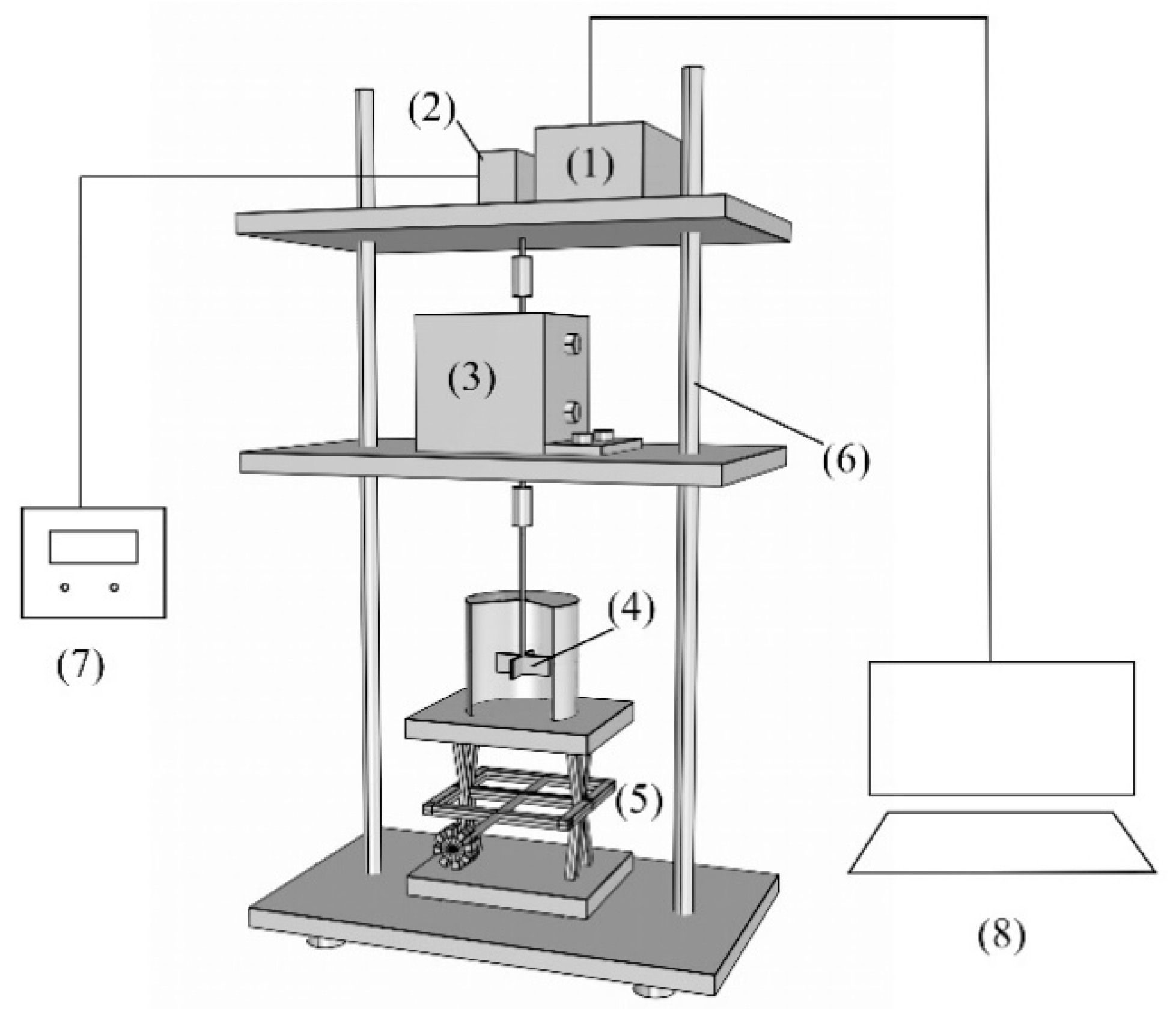
Figure 1. Structural diagram of the new type of gangue slurry rheometer. (1) Pulse generator; (2) torque servo motor; (3) torque sensor; (4) mixing blade; (5) rotating lifting test bench; (6) platform bracket; (7) stable voltage and constant current power supply; and (8) electromechanical control computer.
Processes 13 00789 g001
Figure 2. New type of gangue slurry rheometer.
Processes 13 00789 g002
Figure 3. Working principle diagram of new type of gangue slurry rheometer (O is mixing center; R1 is mixing blade radius; R2 is mixing drum radius, m; Ω is rotation angular velocity of stirring blades, rad/s; h is height of stirring blades, m; and L is distance between mixing blade and bottom of cylinder, m).
Processes 13 00789 g003
Figure 4. Schematic diagram of the end slurry movement.
Processes 13 00789 g004
Figure 5. Fitting curve of different angular velocities and blade edge torques.
Processes 13 00789 g005
Figure 6. The size of the propeller.
Processes 13 00789 g006
Figure 7. Three-dimensional model of blade and mixing drum.
Processes 13 00789 g007
Figure 8. Mesh of the model.
Processes 13 00789 g008
Figure 9. Cloud map of velocity distribution on the observation surface at different rotational speeds.
Processes 13 00789 g009
Figure 10. Cloud map of pressure distribution on the observation surface at different rotational speeds.
Processes 13 00789 g010
Figure 11. Torque variation curves on the blade at different speeds.
Processes 13 00789 g011
Figure 12. Fitting curve of different angular velocities and rotational axis torques.
Processes 13 00789 g012
Table 1. Test ratio of gangue slurry.
ContentCementFly AshGangueWater
76%76 g228 g456 g240 g
Table 2. Test results of slurry with a concentration of 76%.
n (r/min)200250300350400
M (N·m)0.02550.02620.02890.02990.033
Ω (rad/s)20.93526.17331.40936.62841.888
Table 3. Physical parameters of slurry.
Physical Parameters
Density1800 kg / m 3
Viscosity1.89 Pa s
Yield stress96.49 Pa
Table 4. Simulated torque values on the blade at different speeds.
No.Blade Speed (rpm/min)Blade Angular Velocity (rad/s)Blade Torque (N·m)
120020.93330.02531
225026.16660.02721
330031.40.02912
435036.63330.03102
540041.86670.03292
Table 5. Comparison of rheological parameters between setup (test) and simulated values.
Physical ParametersSet (Test) ValueSimulated ValueRelative Error
Viscosity (Pa·s)1.891.921.59%
Yield stress (Pa)96.4998.422%
Disclaimer/Publisher’s Note: The statements, opinions and data contained in all publications are solely those of the individual author(s) and contributor(s) and not of MDPI and/or the editor(s). MDPI and/or the editor(s) disclaim responsibility for any injury to people or property resulting from any ideas, methods, instructions or products referred to in the content.