Article

An Investigation of the Heating Performance of a Groundwater-Based Air Conditioning System for an Agricultural Greenhouse

1
Graduate Faculty of Interdisciplinary Research, University of Yamanashi, 4-3-11 Takeda, Kofu 400-8511, Yamanashi, Japan
2
Isuzu Motoes Limited, 8 Tsuchidana, Fujisawa 252-0881, Kanagawa, Japan
3
Interdisciplinary Graduate School of Engineering, University of Yamanashi, 4-3-11 Takeda, Kofu 400-8511, Yamanashi, Japan
4
Department of Applied Physics, National Defense Academy, 1-10-20 Hashirimizu, Yokosuka 239-8686, Kanagawa, Japan
*
Author to whom correspondence should be addressed.
Processes 2025, 13(3), 778; https://doi.org/10.3390/pr13030778
Submission received: 27 January 2025 / Revised: 28 February 2025 / Accepted: 6 March 2025 / Published: 7 March 2025
(This article belongs to the Special Issue Heat and Mass Transfer Phenomena in Energy Systems)

Abstract

:
Food shortages due to the decreasing arable land area, which is a consequence of the increasing global population, have brought greater attention to greenhouses. However, the cost of air conditioning in greenhouses is high. Therefore, in this study, the heating performance of a low-running-cost air conditioning system using groundwater was evaluated in winter in an agricultural greenhouse. The system consisted of a temperature control room in an agricultural greenhouse and a groundwater recirculation system. The pumped groundwater was passed through a polytube heat exchanger panel and stored in a recirculation tank. The stored water circulated back to the heat exchanger to create a water recirculation system. When operated with only a single 250 L recirculation tank, the temperature in the temperature control room was maintained at 4.9–19.4 °C, even when the maximum and minimum outdoor air temperatures were 12.6 and −2.3 °C, respectively. To achieve a higher minimum temperature in the temperature control room, a method was developed to enable the system to switch from the recirculating water to flowing groundwater when the recirculating water temperature fell below the groundwater temperature. Consequently, the minimum temperature in the temperature control room could be maintained at 8.0 °C. In an experiment in which the capacity of the recirculation tank was tripled (750 L), the minimum temperature was maintained at 7.9 °C, which is a stable temperature for cucumber cultivation. These results indicate that the heating capacity of the proposed system is equivalent to that of ACCFHES (An aquifer coupled cavity flow heat exchanger system) and other heating systems for winter heating. Therefore, this proposed method makes it possible to cultivate plants that grow in a climate similar to that of cucumbers at a low running cost. The amount of heating capacity that could be extracted simply by circulating groundwater was also revealed.

1. Introduction

An increase in the global population has led to a decrease in the amount of arable land in recent years, resulting in food shortages. Greenhouse agriculture has attracted attention as a solution to this problem. By using air conditioning to create a climate suitable for crops, greenhouse agriculture facilitates crop cultivation in areas where outdoor crop cultivation is impossible. In addition, greenhouse crops require fewer chemical fertilizers and pesticides than outdoor crops. These advantages notwithstanding, the cost of air conditioning in greenhouses is high. Runkle and Both [1] reported that greenhouse heating accounts for 65–85% of the total energy used in agricultural greenhouses. Furthermore, according to Rorabaugh et al. [2], heating costs account for 70–85% of the total expenses in cold regions, such as Canada, the United Kingdom, and the Netherlands, and up to 50% in warm regions, such as the southwestern United States, Mexico, Spain, and Israel. With soaring fuel prices, reducing heating costs has become an urgent issue.
Most previous studies on reducing heating costs have focused on improving the energy efficiency of greenhouses. The simplest heating control method is proportional–integral–differential control, which measures the temperature inside a greenhouse and turns on the heating when the temperature falls below a certain threshold. However, the climate inside a greenhouse is affected by various factors, such as solar radiation, outdoor air temperature, and increased humidity due to irrigation. In other words, a greenhouse is a dynamic, nonlinear, multi-input system that requires a complex approach to achieve temperature control. Therefore, research is being conducted on temperature control using feedback control with advanced control algorithms [3] and model-predictive control incorporating model predictions [4]. Artificial intelligence approaches have also been adopted [5,6], for example, fuzzy control, proposed by Azaza et al. [7], and genetic algorithms, proposed by Xu et al. [8]. Hybrid control approaches, which combine multiple control methods rather than simply using one method, have been shown to reduce energy costs by 9% on cold days [9]. Given the increased focus on environmental issues, the use of renewable energy is also attracting attention. The total energy consumption during greenhouse cultivation includes energy expended in pumping, irrigation, and heating. Pumping and irrigation are generally performed using diesel systems. Mostefaoui and Amara [10] reported that solar power generation systems are more cost-effective than diesel systems, even after considering the replacement costs. Benli and Durmuş [11] installed ten solar collectors outside a greenhouse and fed heated air into the greenhouse, reducing the energy required for heating. According to them, ~18–23% of the total daily energy needs could be supplied within 3–4 h. However, this is not a realistic solution owing to the large footprints of solar collectors. Another method being investigated is the use of the underground or groundwater temperature, which is relatively constant throughout the year. Sethi and Sharma proposed an aquifer coupled cavity flow heat exchanger system (ACCFHES). In this system, deep aquifer water from irrigation wells is stored in a moat around the greenhouse. Pipes are installed in the moat, and air is passed through the pipes to create air with a temperature close to that of the deep aquifer water, which is then drawn into the greenhouse [12]. The results showed that the temperature in the greenhouse was maintained 6–7 °C lower than the ambient temperature in midsummer and 7–8 °C higher in midwinter. Ghosal et al. [13] proposed an underground air heat exchanger, in which heat exchange pipes were buried underground, and the greenhouse air was passed through the heat exchanger to regulate the temperature. By using this heat exchanger, the temperature in the greenhouse could be maintained 3–4 °C lower than the outdoor air temperature in midsummer and 6–7 °C higher in midwinter. These systems have the advantage of significantly reducing air conditioning costs, as they use renewable energy. However, despite their relatively high heating capacity, they require abundant groundwater, and in areas where temperatures drop significantly below 0 °C, they fail to maintain the temperatures necessary to grow crops. Attempts have also been made to use geothermal heat pumps in greenhouses. Takeda and Okazawa [14] and Takeda and Higuchi [15] reported that when a direct expansion heat pump was applied for temperature control in a greenhouse, the primary energy use was reduced by 43.6% when heavy oil boilers were used. Thus, many of these technologies have limited applicability and have not led to a significant reduction in energy consumption. In systems that use aquifers or geothermal heat for temperature control, the units of heat exchange are buried underground, which increases the cost of construction, maintenance, and repair. Compared to conventional underground systems, this system is less expensive and has the same heating capacity as a conventional ACCFHES [12]. On the other hand, for agricultural systems on land unsuitable for arable land, it is required that the salt in the groundwater can be removed [16]. Photovoltaic panels are used to provide this power, and salt removal is carried out using fuel cells at night. In other words, hydrogen is generated by photovoltaic panels during the day, and the hydrogen is used to generate electricity in fuel cells at night [17].
Toriyama et al. [18,19] reported an insulated cultivation area created in a greenhouse, with groundwater passing through vinyl tubes installed on the ceiling and the ground serving as a heat source. The system proposed in this paper is a novel temperature control system that utilizes geothermal energy, but with the main heat exchange equipment installed within the system on the ground surface, and it also uses the thermal effects of sunlight. Consequently, the temperature inside the greenhouse could be maintained at ≥15 °C even when the outdoor air temperature was −8 °C. The ideal temperatures for growing tomatoes and cucumbers range from 5 to 35 °C and from 10 to 35 °C, respectively. Therefore, this system could maintain the required temperature even during midwinter. Salty groundwater can be used as-is for temperature control in the proposed system. However, the system can only be implemented in areas with abundant groundwater. To address this limitation, this study attempted to expand the system to recirculate the groundwater used in the system. In addition, methods for switching from recirculating water to free-flowing groundwater flow and adding a recirculation tank were investigated and evaluated for heating performance.

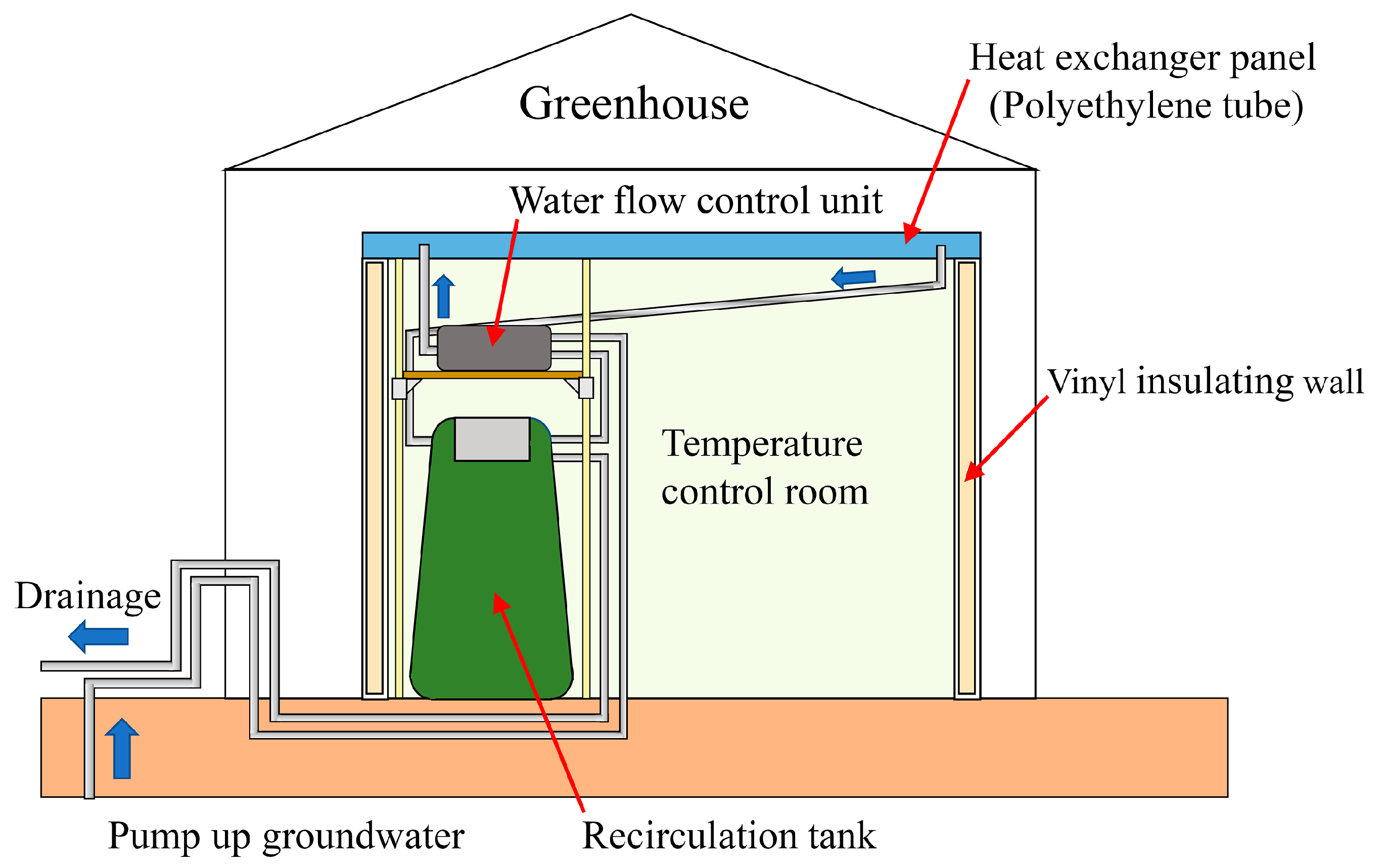
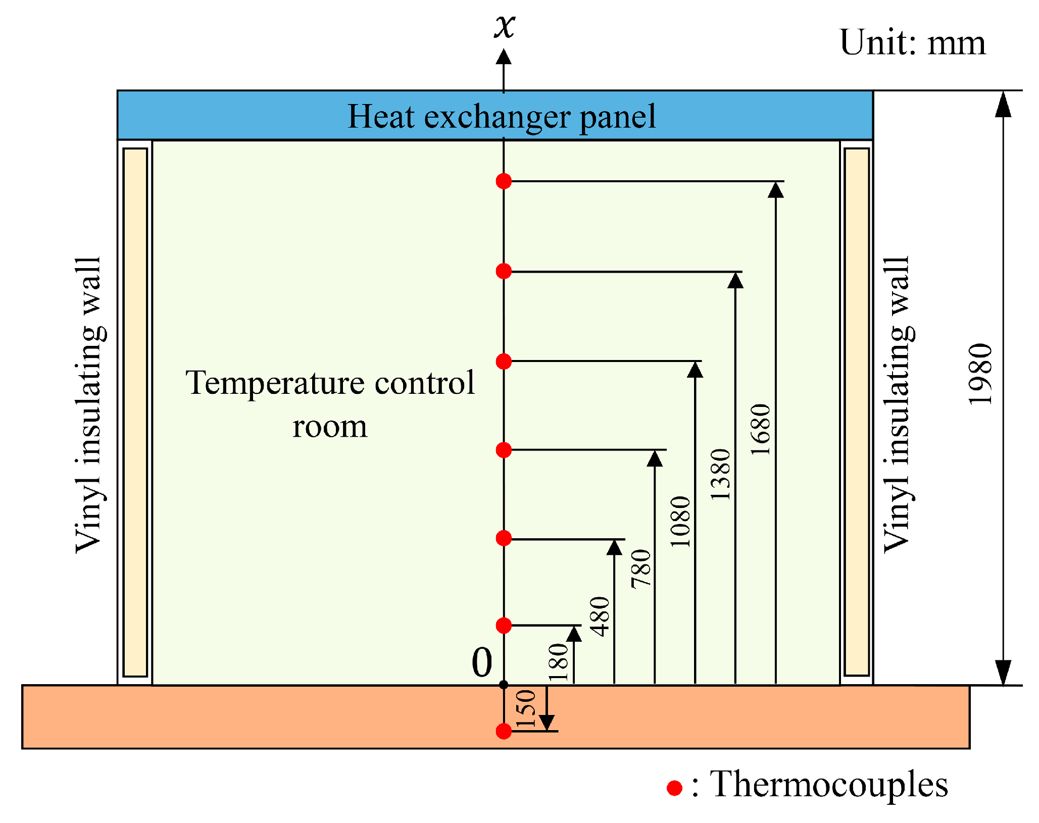
2. Experimental Setup and Methods

Figure 1 shows a schematic of the experimental setup. An all-glass greenhouse (DAISEN Co., Ltd., Aichi, Japan, NAC–3) was used in the experiment, with an opening, span, and height of 3600, 5643, and 2800 mm, respectively. The greenhouse was constructed in the courtyard of the Faculty of Engineering at the University of Yamanashi, Japan. A temperature control room was constructed inside the greenhouse. FRP Compose Bata (UBE EXSYMO Co., Ltd., Tokyo, Japan, □50) with a cross section of 50 mm × 50 mm was used for the columns of the temperature control room with dimensions of 2530 mm (width) × 3940 mm (depth) × 1980 mm (height). The columns were assembled using joints made of welded steel square pipes (outer size: 60 mm × 60 mm and thickness: 3 mm). Heat-insulating sidewalls were created by affixing a closed-cell polyolefin film (C.I. TAKIRON Corporation, Tokyo, Japan, Sky Coat 5 Air Plus) with excellent heat retention to allow light to enter through the sidewalls. This film was applied to both the inside and outside of the temperature control room to create a 50 mm air layer between them, further enhancing the heat-retaining properties of the structure. A wire mesh of steel rods (diameter: 6 mm), welded at 75 mm intervals, was installed on the ceiling of the temperature control room, and polytubes (JOUSEI Co., Ltd., Ehime, Japan, tube width: 250 mm and thickness: 0.1 mm) for heat exchange were placed on top. Groundwater was pumped from a shallow well on campus by using a domestic water pump (KAWAMOTO PUMP MFG. Co., Ltd., Aichi, Japan, NF3). The polytubes used in the heat exchanger are installed on a coarse wire mesh. Therefore, if the polytube is too long, it is difficult for water to flow inside. To avoid this phenomenon, the length of the polytube that does not block the flow of water was first determined in preliminary experiments, and the dimensions of this system were determined based on this length. After the impurities were removed using a filter (NIHON FILTER Co., Ltd., Kanagawa, Japan, NFH–A–10–E), the water was passed through polytubes in the ceiling, with the water volume passing through being regulated using a ball valve; the volumetric flow rate was measured using a volumetric flow meter (AICHI TOKEI DENKI Co., Ltd., Aichi, Japan, ND20–NATAAA–RC). The water passing through the polytubes was temporarily stored in a 250 L recirculation tank (KODAMA PLASTICS Co., Ltd., Gifu, Japan, RWT–250) and pumped into the polytubes using a submersible pump (TSURUMI MANUFACTURING Co., Ltd., Osaka, Japan, FP–5S) installed inside the tank for recirculation. Therefore, when the recirculation tank was full, the groundwater was no longer pumped, and the temperature was controlled only through water circulation. Polytubes used in the heat exchanger of the proposed system are easily deformed, so the amount of water fed into the tubing does not flow out smoothly, or conversely, the outflow temporarily increases, causing instability in the outlet flow rate. This instability also affects the flow rate on the inlet side. Therefore, a 250 L recirculation tank that can sufficiently cover the water volume in the heat exchanger (polytubes) was installed as a damper to mitigate this instability.
Owing to the gaps between the polytubes in the ceiling of the temperature control room, natural convection could cause warm air to escape. Therefore, the ceiling was covered with a 0.1 mm thick polyvinyl chloride sheet before conducting the experiment.
Figure 2 shows a schematic of the heat exchanger panel on the ceiling of the temperature control room. The outer frame of the heat exchanger panel was made of the same FRP Compose Bata as the frame of the temperature control room, and its four corners were joined using the same metal joints as those used in the frame of the temperature control room. A total of 15 holes were drilled into each of the two FRP Compose Batas located on the long sides; joints for water flow were installed, and 15 polytubes were connected. As these Compose Batas are hollow, they can be used as water pipes that allow both inflowing and outflowing water to pass through multiple polytubes. In addition, the inlet and outlet for the water from the recirculation tank were installed at diagonal locations in the heat exchanger, and K-type thermocouples for measuring the water temperature were installed at these locations.
Figure 3 shows the layout of the thermocouples used to measure the room temperature. The x in the diagram indicates the vertical distance from the ground. K-type thermocouples were used to measure the room and ground temperatures. Seven thermocouples were installed in the vertical direction at approximately the center of the room. The room temperature was measured at a point 180 mm above the ground and five points every 300 mm in the vertically upward direction. Ground temperature was measured at a single point at a depth of 150 mm. Measurements of wind speed and humidity at the location where this system is installed were not conducted.

3. Uncertainty Analysis

In this study, the following two measurement uncertainties arise from the sensitivity of the instruments used:
-
Temperature measurement uncertainty: The uncertainty of the temperature measurement unit is ±0.5 °C (catalog value). For the uncertainty of the temperature measurement, the uncertainty of the thermocouple should also be taken into account, but since the uncertainty of the temperature measurement unit is much larger, ±0.5 °C is acceptable;
-
Uncertainty due to flow measurement: The uncertainty of the flowmeter is ±2%RS (Read Scale). For the water volume, a variable flow rate of 0.14 L/min, due to an adjustment at the ball valve, is considered as uncertainty.

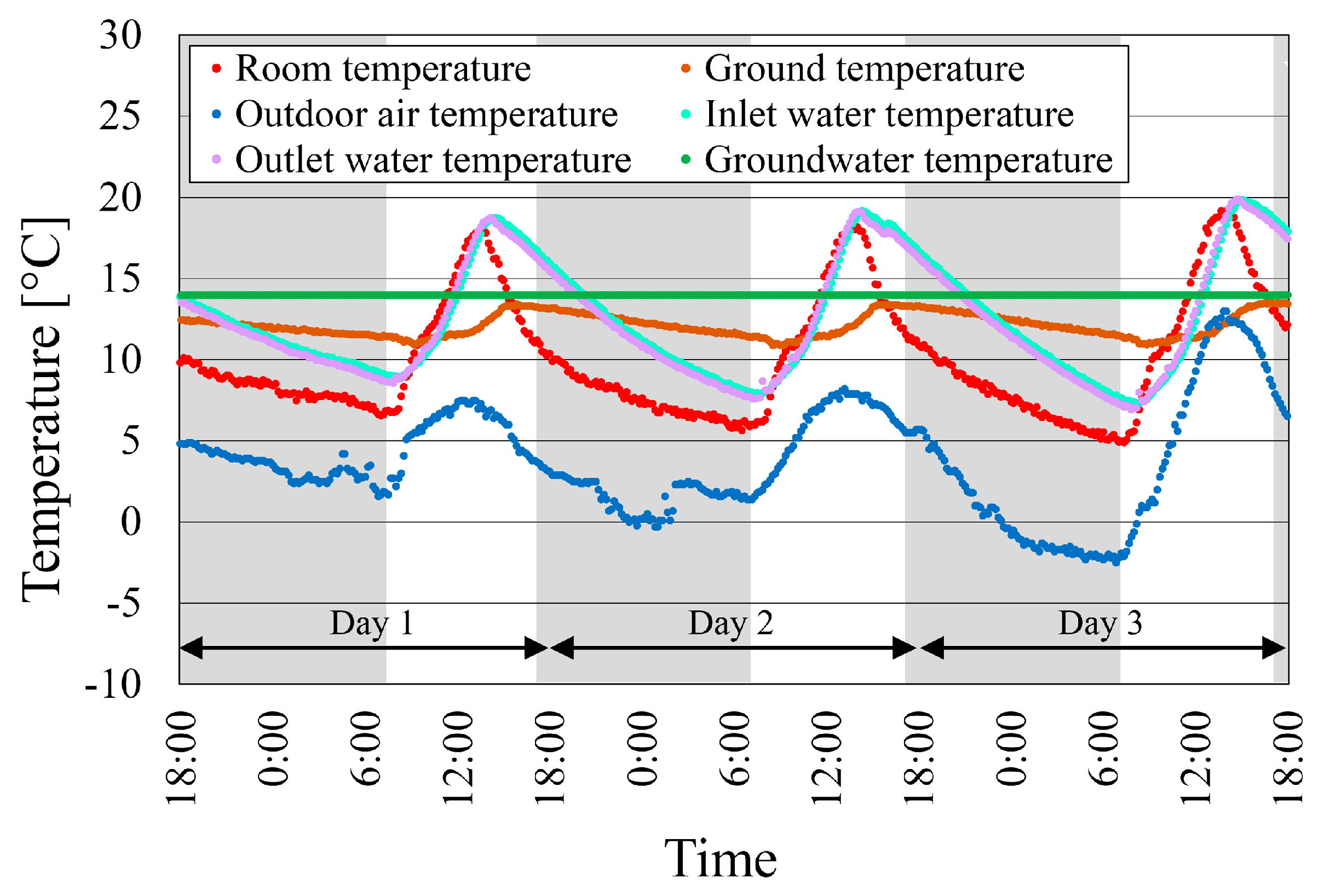
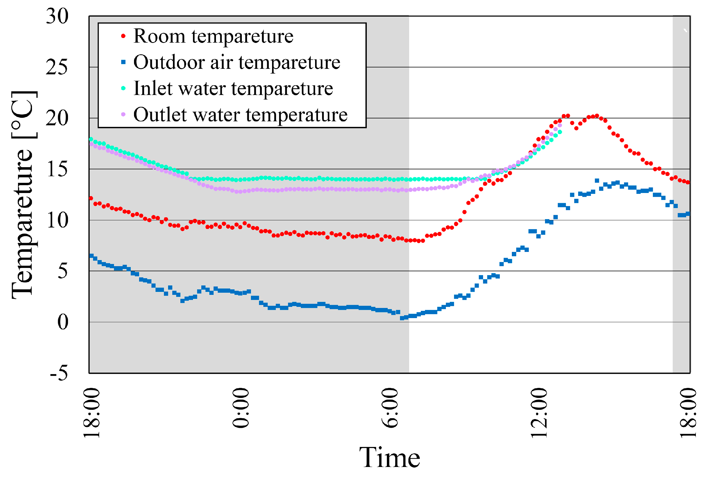
4. Heating Performance Evaluation

4.1. Performance Evaluation with Recirculation Only

To evaluate the heating performance of the system with only recirculation, a performance test was conducted for three consecutive days, from 18:00 on 28 January 2021 to 18:00 on 31 January 2021. The volumetric flow rate of the circulating water was m ˙ = 1.4 × 10 4   m 3 / s , and the temperature was measured every 10 min. Figure 4 shows the changes in the temperature in the temperature control room, the ground temperature, the outdoor air temperature, the groundwater temperature, and the inflow and outflow water temperatures to the heat exchanger over three days. The gray shaded periods in Figure 4 indicate the time from sunset to dawn. Outdoor air temperatures fluctuated more significantly on the third day, with the minimum and maximum temperatures being −2.3 and 12.6 °C, respectively, while the average temperature was ~ 5 °C on all three days. The temperature in the temperature control room increased after sunrise and decreased after noon; however, the rate of temperature decrease from noon to sunset was greater than that after sunset. This is because the temperature inside the temperature control room increased during the daytime owing to solar radiation; however, in the evening, the temperature dropped rapidly because the amount of sunlight decreased, and the temperature difference with respect to the outdoor air temperature widened. However, during the night, the temperature difference with respect to the outdoor air temperature decreased; therefore, the rate of temperature decrease was also smaller than that of from noon to sunset. During these three consecutive days, the minimum room temperatures were 6.6, 5.8, and 4.9 °C, and the maximum room temperatures were 18.1, 18.2, and 19.4 °C, which were much smaller than the maximum and minimum variations in outdoor air temperatures. Therefore, this system not only heated the greenhouse but also suppressed daily temperature fluctuations. Regarding the underground temperature, temperature fluctuations were considerably suppressed, with minimum and maximum temperatures of 11.0 and 13.5 °C, respectively, over three consecutive days. These results indicate that cucumbers can be grown simply by circulating the groundwater, as long as the temperature can be controlled within the specified temperature range. However, regarding the temperature of the water flowing into the heat exchanger, the water temperature during the night was slightly higher than the room temperature and decreased with time. The water temperature during the daytime increased in the same manner as the temperature in the temperature control room until noon; it reached a value slightly higher than the maximum temperature in the temperature control room and then decreased slowly. Regarding the inlet and outlet temperatures of the heat exchanger, the inlet water temperature was higher and lower than the outlet water temperature when the temperature of the circulating water decreased and increased, respectively. In other words, heat was released from and absorbed by the heat exchanger when the water temperature decreased and increased, respectively. The maximum water temperature was higher than the temperature in the temperature control room. This increase in water temperature occurred because part of the solar energy incident on the temperature control room was absorbed by the water in the polytube. These mechanisms were thought to reduce temperature fluctuations in the temperature control room.
To confirm the vertical temperature distribution in the temperature-controlled room, the daily temperature variation were measured over time (Figure 5) on the last day of the three-day period. Here, x in the figure legend indicates height from the ground. The gray-shaded periods in the figure indicate the time from sunset to dawn. As shown in Figure 5, although a variation of ~ 2 °C was observed throughout the room, no systematic temperature distribution by height was observed. This indicated an absence of any temperature layers in the temperature control room and the realization of an almost uniform temperature distribution. However, from the time when the temperature in the temperature control room showed an overall maximum value (at ~ 14:00) to sunset, the temperature near the ceiling (x = 1680 mm) was slightly lower than that at other heights. This is because the air near the ground in the temperature control room was heated by the energy of sunlight falling on it. The air near the ceiling was also heated by the heat exchanger; however, the air at other heights was heated by the grand surface. When the temperature in the temperature control room decreased significantly, the temperature difference between the polytubes and the temperature in the temperature control room increased, resulting in more heating near the ceiling than at other heights. Thus, a smaller air temperature difference was observed between the ceiling and air at other heights.
Figure 6 shows the temporal variations in the amount of heat exchanged per unit time in the heat exchanger on the third day.
Q ˙ = ρ C p m ˙ T o T i ,
where Q ˙ W is the amount of heat exchanged per unit time, ρ k g / m 3 is the density of water, C p   J / kg · K is the isobaric specific heat of water, m ˙ m 3 / s is the volumetric flow rate, T i   ° C is the inlet temperature of the heat exchanger, and T o   ° C is the outlet temperature of the heat exchanger. The values of the physical properties at 15 °C, which is approximately halfway between the maximum and minimum values of the water temperature, were considered. That is, ρ = 999.0 kg / m 3 , and C p = 4190.0 J / kg · K . Gray-shaded periods in the figure indicate the time from sunset to dawn. In the light-blue area of the figure, the heat exchange rate was negative, indicating that heat was dissipated from the heat exchanger. During the absence of solar radiation, the heat exchanger always dissipated Q ˙ 2 50   W of heat. After sunrise, the heat exchanger was heated via solar radiation; the outlet temperature began increasing and continued to increase further for a certain time. Subsequently, as solar radiation increased toward noon, the heat exchanger was in a state of heat absorption, and the maximum heat absorption at this time was Q ˙ 450   W . Toward the evening, the amount of heat absorbed decreased, and heat began to be released again before sunset. The amount of heat released from the heat exchanger on this day was 14.7 MJ, and the amount of heat recovered was 6.0 MJ. As shown in Figure 4, the water temperature on the hot side of the heat exchanger recovered to approximately the same temperature every day, indicating that thermal energy was supplied to the circulating water from outside the heat exchanger. This energy is thought to be supplied by sunlight falling on the recirculation tank during the day, which heated the water in the recirculation tank.

4.2. Improved Temperature Control by Adding Groundwater Flow

The system described in the previous subsection was able to maintain a temperature suitable for growing cucumbers 5   ° C . However, in cooler climates, this temperature level may not be maintained. Therefore, to increase the temperature in the temperature control room at night to the maximum level possible, the system switched to free-flowing groundwater when the circulating water temperature fell below the groundwater temperature. This technique can only be used in areas with somewhat abundant groundwater, but it is practical in areas with few cold days. Figure 7 shows the changes in the temperature in the temperature control room, the outdoor air temperature, and the inlet and outlet temperatures of the heat exchanger when the circulating water temperature fell below the groundwater temperature of 14 °C during the night and the system switched from recirculating water type to free-flowing groundwater type. The measurement of the inlet and outlet water temperatures in the heat exchanger had stopped around noon, but it was possible to check the temperature transitions during the night. In this experiment, the system switched to a free-flowing groundwater system at 22:00. The temperature in the temperature control room at this switchover time was 9.8 °C, and the lowest temperature was 8.0 °C at 7:10. In other words, the temperature drop was only 1.8 °C. Conversely, the temperature drop from 22:00 without groundwater was from 8.4 °C (at 22:00) to 4.9 °C (at 7:20) = 3.5 °C on the last day (Figure 4). By switching to free-flowing groundwater, the temperature drop could be reduced by approximately half. The results demonstrate that switching to running groundwater is an effective countermeasure against colder days.

4.3. Improved Temperature Control by Adding Recirculation Tanks

As the method described in Section 4.2 is only applicable to areas with abundant groundwater, alternative methods were investigated. Notably, to maintain a high temperature in the temperature control room at night, increasing the amount of heat released from the heat exchanger is necessary; therefore, additional recirculation tanks were added. As described in Section 4.1, sunlight falling on the recirculation tank increased the temperature of the water inside the tank (Figure 6). Therefore, an increase in the number of tanks corresponds to increased amount of recirculating water that can keep the temperature control room warm during the night. In this experiment, two additional tanks identical to the existing tank were installed to increase the water storage capacity from 250 to 750 L. As for the 750 L tank, the experiment was conducted because this system has a volume that can accommodate up to three 250 L recirculation tanks.
Figure 8 shows the changes in the temperature of the temperature control room, the outdoor air temperature, and the water temperature at the inlet of the heat exchanger from 12:00 on 3 February 2023 to 12:00 on 6 February 2023. The maximum and minimum outdoor air temperatures were 15.5 and 0.1 °C, respectively, slightly warmer than on the day of the experiment with a single recirculation tank. Focusing on the water temperature at the inlet of the heat exchanger, the maximum temperature during the day increased with each passing day. This was attributed partly to the low outdoor air temperature on the first day, as well as to the increase in the temperature in the temperature control room, indicating that the amount of solar radiation increased with each passing day. However, the minimum water temperature during the night remained almost the same (10.2 °C). In the case of only a single recirculation tank (Figure 4), the minimum water temperature changed with the outdoor air temperature. However, in this case, the water temperature at the heat exchanger inlet was almost unaffected by the outdoor air temperature owing to the presence of an abundant amount of circulating water. Based on this result, the minimum temperature of circulating water is expected to be maintained at ~10 °C, even when the outdoor air temperature is lower than 0.1 °C. Under these conditions, the minimum temperature in the air-conditioned room was 7.9 °C (7.8 °C higher than the outdoor temperature) on both the second and third days, indicating that a room temperature higher than the minimum temperature required for cucumber cultivation could be maintained. In other words, a 250 L recirculation tank was somewhat insufficient for the scale of the agricultural greenhouse used in this experiment, and the number of recirculation tanks will need to be increased. The appropriate number of recirculation tanks could not be determined in this study and needs to be evaluated in future studies.

5. Conclusions

In this study, the heating performance of a low-running-cost agricultural greenhouse with an air conditioning system using groundwater was evaluated in winter. According to this study’s findings, in the areas with abundant groundwater, the use of circulating groundwater as a heat source with a 250 L recirculation tank can help maintain a sufficiently high temperature for cucumber cultivation (4.9–19.4 °C). To cope with more severe low-temperature conditions, a method was proposed to enable the system to switch from the circulating water to free-flowing groundwater when the circulating water temperature falls below the groundwater temperature. With the use of this method, the minimum temperature in the temperature control room could be maintained at 8.0 °C. In the experiment in which the capacity of the recirculation tank was tripled (750 L), it was found that the minimum temperature could be maintained at 7.9 °C, providing a stable temperature for cucumber cultivation. In the case of the heating system using ACCFHES, the temperature difference between the room temperature of the greenhouse and the outside temperature in winter is about 7–8 °C [12], and the system using solar panels and heating equipment together also achieves a temperature range of 7–8 °C [20]. Furthermore, the proposed system does not require the main parts of the equipment to be buried underground, making maintenance and troubleshooting easier and keeping initial investment and running costs low.
This method makes it possible to cultivate plants that grow in a climate similar to that in which cucumbers grow at a low running cost. In this study, we could maintain temperatures suitable for cucumber cultivation (5–35 °C), but not for tomato cultivation (10–35 °C). To achieve the temperature required for tomato cultivation, the amount of heat released from the heat exchanger at night must be increased. Therefore, in a future project, a system that uses hot water generated by a solar heat collector at night will be developed and evaluated. In addition, long-term measurements in various regions and seasons and their evaluation will be necessary to determine what level of heating or cooling capacity can be expected when this system is used in various climates.

Author Contributions

Conceptualization, K.T.; methodology, K.T. and K.W.; validation, K.T., S.F., and S.T.; investigation, K.W. and I.K.; resources, K.T.; data curation, K.T., K.W., and I.K.; writing—original draft preparation, K.T.; writing—review and editing, S.T.; visualization, K.T.; supervision, K.T.; project administration, K.T.; funding acquisition, K.T. All authors have read and agreed to the published version of the manuscript.

Funding

This work was supported by the Japan Racing Association (JKA), and promotional funds were from KEIRIN RACE (2020M-200, 2022M-276).

Data Availability Statement

Data are contained within the article.

Conflicts of Interest

Author Kyosuke Wakishima was employed by the company Isuzu Motoes Limited. The remaining authors declare that the research was conducted in the absence of any commercial or financial relationships that could be construed as a potential conflict of interest.

References

  1. Runkle, E.; Both, A.J. Greenhouse Energy Conservation Strategies; Extension Bulletin; Michigan State University: East Lansing, MI, USA, 2012; pp. 1–16. [Google Scholar]
  2. Rorabaugh, P.A.; Jensen, M.H.; Giacomelli, G.G. Introduction to Controlled Environment Agriculture and Hydroponics; Controlled Environment Agriculture Center: Tucson, AZ, USA, 2002; pp. 1–130. [Google Scholar]
  3. Lijun, C.; Shangfeng, D.; Yaofeng, H.; Meihui, L. Linear quadric optimal control applied to the greenhouse temperature hierarchal system. IFAC-PapersOnLine 2018, 15, 712–717. [Google Scholar] [CrossRef]
  4. Ghoumari, M.Y.E.; Tantau, H.J.; Serrano, J. Non-linear constrained MPC: Real-time implementation of greenhouse air temperature control. Comput. Electron. Agric. 2005, 49, 345–356. [Google Scholar] [CrossRef]
  5. Monjezi, P.H.; Taki, M.; Mehdizadeh, S.A.; Rohani, A.; Ahamed, M.S. Prediction of Greenhouse Indoor Air Temperature Using Artificial Intelligence (AI) Combined with Sensitivity Analysis. Horticulturae 2023, 9, 853. [Google Scholar] [CrossRef]
  6. Hoseinzadeh, S.; Garcia, D.A. Ai-driven innovations in greenhouse agriculture: Reanalysis of sustainability and energy efficiency impacts. Energy Convers. Manag. X 2024, 24, 100701. [Google Scholar] [CrossRef]
  7. Azaza, M.; Echaieb, K.; Tadeo, F.; Fabrizao, E.; Lqbal, A.; Mami, A. Fuzzy decoupling control of greenhouse climate. Arbian J. Sci. Eng. 2015, 40, 2805–2812. [Google Scholar] [CrossRef]
  8. Xu, F.; Chen, J.; Zhang, L.; Zhan, H. Self-tuning fuzzy logic control of greenhouse temperature using real-coded generic algorithm. In Proceeding of IEEE 9th International Conference on Control, Automation, Robotics and Vision, Singapore, 5–8 December 2006. [Google Scholar]
  9. Shen, Y.; Wei, R.; Xu, L. Energy consumption prediction of a greenhouse and optimization of daily average temperature. Energies 2018, 11, 65. [Google Scholar] [CrossRef]
  10. Mostefaoui, Z.; Amara, S. Renewable energy analysis in the agriculture-greenhouse farms: A case study in the Mediterranean region (Sidi Bel Abbes, Algeria). Environ. Prog. Sustain. Energy 2018, 38, e13029. [Google Scholar] [CrossRef]
  11. Benli, H.; Durmuş, A. Performance analysis of a latent heat storage system with phase change material for new designed solar collectors in greenhouse heating. Solar Energy 2009, 83, 2109–2119. [Google Scholar] [CrossRef]
  12. Sethi, V.P.; Sharma, S.K. Thermal modeling of a greenhouse integrated to an aquifer coupled cavity flow heat exchanger system. Solar Energy 2007, 81, 723–741. [Google Scholar] [CrossRef]
  13. Ghosal, M.K.; Tiwari, G.N.; Srivastava, N.S.L. Thermal modeling of a greenhouse with an integrated earth to air heat exchanger: An experimental validation. Energy Build. 2004, 36, 219–227. [Google Scholar] [CrossRef]
  14. Takeda, T.; Okazawa, R. Study on energy saving effect of ground source heat pump applied as greenhouse air conditioning system. In Proceeding of the International Conference on Power Engineering-2019, Kunming, China, 21–25 October 2019. [Google Scholar]
  15. Takeda, T.; Higuchi, S. Evaluation of the effectiveness of direct expansion geothermal heat pumps in agricultural facilities. In Proceedings of the Yamanashi Industry-Academia-Government Collaborative Research Exchange Program, Yamanashi, Japan, 10 October 2019. (In Japanese). [Google Scholar]
  16. Nurettin Sezer, N.; Bayhan, S. Integrated solar-powered freeze desalination and water electrolysis system with energy recovery and storage for sustainable agriculture in desert environments. Desalination 2025, 595, 118321. [Google Scholar] [CrossRef]
  17. Ishtiaque, M.M.-U.; Saha, P.; Sutradhar, A.; Galib, M.; Hannan, M.A. A sustainable approach to improve the efficiency of earth pipe cooling system. Int. J. Sustain. Eng. 2020, 13, 387–397. [Google Scholar] [CrossRef]
  18. Toriyama, K.; Kawai, M.; Kado, T.; Funatani, S. A study of temperature control system by using groundwater in agricultural greenhouse. In Proceeding of the 49th the Japan Joint Conference on Air-Conditioning and Refrigeration, Tokyo, Japan, 15–17 April 2015. (In Japanese). [Google Scholar]
  19. Toriyama, K.; Funatani, S.; Kobayashi, T. Flow Stabilizing Device in Flow Path, Plant Cultivation House Including the Same, and Flow Stabilizing Method in Flow Path. JP Patent JP6748956B2, 13 August 2020. (In Japanese). [Google Scholar]
  20. Attar, I.; Naili, N.; Khalifa, N.; Hazami, M.; Lazaar, M.; Farhat, A. Experimental study of an air conditioning system to control a greenhouse microclimate. Energy Convers. Manag. 2014, 79, 543–553. [Google Scholar] [CrossRef]
Figure 1. Diagram of experimental facility.
Processes 13 00778 g001
Figure 2. Diagram of the heat exchanger panel.
Processes 13 00778 g002
Figure 3. Layout of thermocouples to measure the temperature in the temperature control room.
Processes 13 00778 g003
Figure 4. Temporal variations in the temperatures at various locations inside and outside the temperature control room for three days from 18:00 on 28 January 2021 to 18:00 on 31 January 2021.
Processes 13 00778 g004
Figure 5. Temporal variations in the temperature control room at various vertical positions from 18:00 on 30 January 2021 to 18:00 on 31 January 2021. The x indicates the height from the ground.
Processes 13 00778 g005
Figure 6. Temporal variations in the heat exchange rate per unit time in the heat exchanger from 18:00 on 30 January 2021 to 18:00 on 31 January 2021.
Processes 13 00778 g006
Figure 7. Temporal variations in the temperatures at various locations inside and outside the temperature control room using groundwater from 18:00 on 31 January 2021 to 18:00 on 1 February 2021.
Processes 13 00778 g007
Figure 8. Temporal variations in the temperatures at various locations inside and outside the temperature control room from 12:00 on 3 February 2023 to 12:00 on 6 February 2023.
Processes 13 00778 g008
Disclaimer/Publisher’s Note: The statements, opinions and data contained in all publications are solely those of the individual author(s) and contributor(s) and not of MDPI and/or the editor(s). MDPI and/or the editor(s) disclaim responsibility for any injury to people or property resulting from any ideas, methods, instructions or products referred to in the content.

