Article

A Study on Microstructure-Property Relationships and Notch-Sensitive Fracture Behavior of X80 Steel Welds

1
State Key Laboratory of Oil and Gas Equipment, Tubular Goods Research Institute of CNPC, Xi’an 710077, China
2
College of Pipeline and Civil Engineering, China University of Petroleum, Qingdao 266580, China
*
Author to whom correspondence should be addressed.
Processes 2025, 13(3), 763; https://doi.org/10.3390/pr13030763
Submission received: 29 December 2024 / Revised: 6 February 2025 / Accepted: 11 February 2025 / Published: 6 March 2025

Abstract

:
X80 steel pipelines are widely used in oil and gas transportation, and the quality and fracture behavior of the girth weld have an important influence on the safety and performance of the pipeline. This study presents a comprehensive investigation into the microstructure, mechanical properties, and fracture characteristics of X80 steel welded joints. Through microstructure analysis and mechanical testing, the hardness, impact, and tensile properties of the base metal, heat-affected zone, and weld zone are evaluated. Digital Image Correlation (DIC) technology is employed to scrutinize the strain behavior under quasi-static tensile tests for both smooth and notched round bar specimens, providing a detailed strain distribution analysis. The findings indicate that, while X80 welded joints are well-formed without significant defects, the hardness and impact properties vary across different zones, with the base metal exhibiting the highest impact toughness and the weld zone the lowest. Notched tensile tests reveal that the presence and geometry of notches significantly alter the stress state and deformation characteristics, influencing the fracture mode. The DIC analysis further elucidates the strain concentration and localization behavior in the weld zone, highlighting the importance of notch size in determining the load-bearing capacity and ductility of the welded joints. This study contributes to a deeper understanding of the fracture mechanics in X80 pipeline girth welds and offers valuable insights for the optimization of welding practices and the assessment of pipeline integrity.

1. Introduction

With the rapid development of the economy, the energy demand increases year by year, and high steel grade long-distance pipelines with large capacity are recognized as the first choice for oil and natural gas transportation. X80 pipeline steel has gradually become the mainstream application in oil and gas pipeline projects. It not only meets the normal service conditions of pipelines under large diameter, thin wall thickness, and high transmission pressure, but also, to some extent, reduces the construction cost of pipelines [1,2]. For the welded joints of X80, various welding defects such as cracks, pores, slag inclusions, incomplete penetration, and lack of fusion may occur in the weld and its adjacent heat-affected zone. Additionally, due to human factors, corrosive media, stress, and other reasons, damage can be caused. Once the pipeline leakage accident occurs, it is very susceptible to serious consequences. Therefore, the safe operation of high steel grade pipelines is very important.
The girth weld of a pipeline is a non-homogeneous material that is subjected to uneven thermal cycling during the welding process. Grain coarsening, embrittlement, etc., occur in different regions of the joint, and the mechanical properties of each local region change significantly. The girth welds in X80 steel pipelines are indispensable for the secure transportation of oil and natural gas, yet they remain a focal point of concern due to their susceptibility to defects and microstructural alterations under thermal and mechanical stresses [1,2,3,4]. These welds are critical as they are often the site of potential failure, which could lead to catastrophic consequences. Despite the advancements in welding techniques and material science, the comprehensive understanding of the fracture behavior in girth welds, particularly in relation to notch effects, remains an area ripe for exploration [2,5,6]. Previous research has provided valuable insights into the microstructural characteristics and mechanical properties of girth welds [7,8,9]. Furthermore, notches are known to introduce stress concentrations, which can significantly alter the mechanical behavior of materials [10,11,12]. The presence of notches in girth welds can lead to a more complex stress state, potentially reducing the load-bearing capacity and ductility of joints [10,12].
In terms of fracture mechanisms, traditional methods have some limitations. It is of great interest to carry out research on fracture prediction models based on microscopic mechanisms. To study the microfracture coefficients of the Void Growth Model and Stress Modified Critical Strain Model, it is necessary to calibrate the microfracture coefficients by combining the tensile tests of standard and notched round bars, as well as by combining finite element simulation analysis. Load–displacement data from axial tensile tests of notched round bar specimens are required for the calibration of microfracture coefficients by finite element simulation analysis. Although these models are not directly applied in the current study, they form an important part of our future research plan, where we aim to combine experimental data with finite element simulations to calibrate and validate these models for more accurate fracture prediction in X80 steel welds. In addition, with the development of computer technology and the improvement of camera lens resolution, the method of testing the true stress–strain curves of materials based on Digital Image Correlation (DIC) technology has been widely used.
Therefore, this study will focus on the microstructure and mechanical properties of X80 welded joints firstly, and then perform tensile tests on weld round bar specimens and notched round bar specimens of different sizes. And based on the DIC technique, the true stress–strain curves of welded round bar specimens and notched round bar specimens of different sizes are obtained, which provide corresponding data support for the calculation of fracture coefficients of the microfracture prediction model.

2. Materials and Test Methods

2.1. Materials

The base material (BM) used in the present study is X80 with a diameter of 1219 mm and a thickness of 18.4 mm. The chemical composition was tested on an ARL-4460 direct reading spectrometer at 24 °C, as depicted in Table 1. X80 steel is a type of low-carbon micro-alloyed acicular ferrite cold-rolled steel, which is a special kind of low-alloy, high-strength, and high-toughness pipeline steel. Acicular ferrite pipeline steel is a bainitic ferrite steel without carbides (as shown in Figure 1), and the C content of such pipeline steel is generally less than 0.06%. Since the lower C content may cause a decrease in strength, the strength is increased by increasing the Mn content [13].

2.2. Test Methods

The macrostructure characteristics and microstructure evolution of different zones in welded joints were observed using an Olympus LEXT OLS4100 laser confocal microscope (Tokyo, Japan). The scanning electron microscope (SEM) analysis was conducted using a Shimadzu (Kyoto, Japan) scanning electron microscope, mainly to examine the fracture surfaces. The Vickers hardness measurements were performed on the cross-section under a load of 500 g for 10 s. The impact test was carried out at −10 °C with a specimen size of 10 mm × 10 mm × 55 mm. The 250 kg mass hammer was used for the impact test.
To obtain the stress states under different stress triaxiality, tensile specimens were designed as shown in Figure 2. In addition to the conventional dimension specimens, three types of specimens with different notch sizes were selected for tensile testing, all located in the weld zone (WZ). The notch radii of the three types of specimens were 4 mm, 8 mm, and 12 mm, respectively. The four types of specimens depicted in Figure 2 were subjected to tensile testing on a CMT 5105 testing machine (with a maximum load of 100 kN) at a loading rate of 3 mm/min until the specimens were pulled to failure.

2.3. DIC Test

Digital Image Correlation (DIC) has emerged as a powerful tool for measuring full-field strain and can provide a detailed understanding of strain distribution in welds under tension [14]. However, its application in the context of notched girth welds is still limited. The strain behavior of the different specimens under tensile loading was investigated using the DIC method. Figure 3 shows the uniaxial tensile test procedure of X80 pipe weld specimens under the quasi-static displacement loading mode. Black and white scattering spots were randomly sprayed on the surface of the specimens prior to the test. The strain measurement system consisted of a VIC-3D device and strain analysis software provided by Correlated Solutions Incorporated.

3. Results Analysis

3.1. Microstructure

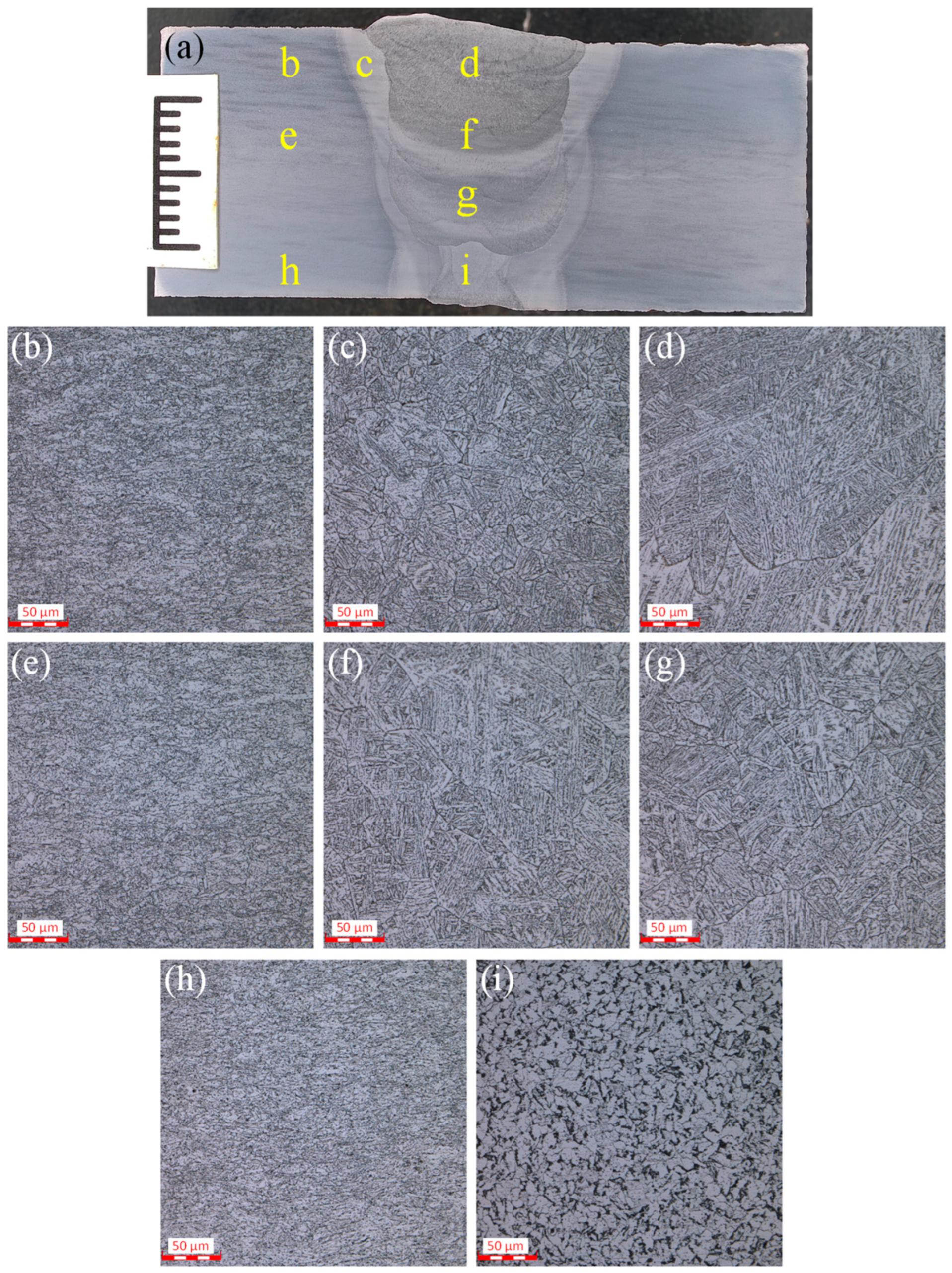
After backing, filling, and capping welding, the cross-sectional morphology of X80 welded joints is shown in Figure 4. It can be observed that the joint was well-formed, with no obvious microstructural defects, and no cracks or incomplete fusion were detected. From Figure 4a, it is evident that the width of the filler weld was significantly greater than that of the backing weld. However, due to the different solidification and shaping conditions of the backing and filler welds, there were slight variations in the shape and dimensions of the post-welding seams, particularly in the dimension of the crown height of the seam. Excessive width variation at the junction between the base material and the weld can lead to a sudden change in the entire cross-section of the joint.
The cross-sectional microstructure of the welded joint can be divided into the weld zone (WZ), the heat-affected zone (HAZ), and the base material (BM). Since each location is subjected to different welding thermal cycles, the HAZ is a heterogeneous continuum with gradients of microstructure and mechanical properties. There are different methods to divide the HAZ, which can be divided into five zones based on the microstructure state, including: fusion zone (FZ), coarse-grain zone, fine-grain zone (FGZ), incomplete recrystallization zone, and age embrittlement zone [15,16].
The microstructures of different regions in Figure 4a show that there were no significant differences in the microstructures of regions b, e, and h, which were quasi-polygonal ferrite (QF)+ granular bainite (GB)+ martensite–austenite constituents (M-A), as depicted in Figure 4b,e,h. The microstructure of the weld was intergranular acicular ferrite (IAF)+GB+ ferrite bainite (FB), and the columnar crystals had no pre-eutectic ferrite precipitation, which indicates that the welding line energy was small. GB was mainly distributed in the coarse-grain area in Figure 4c. The grains were coarse, and the grain boundaries were clear. The M-A in the grain boundaries and lath boundaries was obvious. The microstructure of the fine-grain zone was Ferrite Bainite (PF)+ Pearlite (P)+M-A, as shown in Figure 4i.

3.2. Microhardness

In the manufacturing process, the grain of pipeline steel is refined, the toughness is improved, and the brittleness is reduced through a series of strengthening effects, such as solid solution strengthening and dislocation strengthening. In the welding process, the weld undergoes rapid thermal cycling action, the type of microstructure and the morphology of the crystalline cooling change significantly, the quality of the joint is affected by the microstructure, and there is an inextricable correlation between the two.
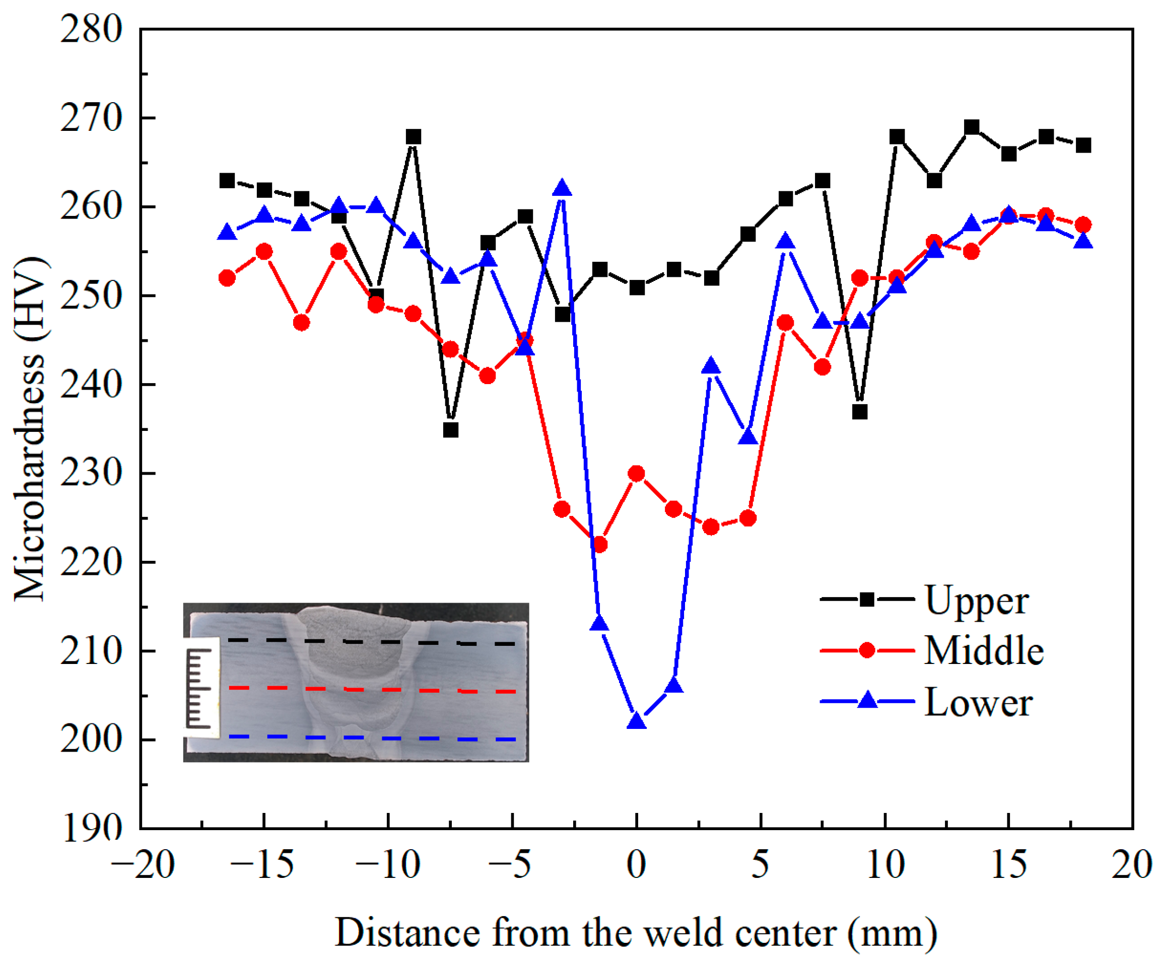
Figure 5 shows the hardness distribution of the cross-section of the welded joints. In the WZ, the hardness distribution is uneven, with higher hardness near the upper surface and the lowest hardness near the lower surface. Due to the low C element content in X80 steel, the microstructure is acicular ferrite, which ensures good weldability and a maximum hardness of about 260 HV. The microstructure in the weld region is mainly IAF+GB+FB, with a decrease in the bainite content and an increase in the ferrite content of the joint, as well as an increase in the grain size, and this distribution of microstructure characteristics results in a decrease in the hardness of the joint. The lowest hardness is in the bottomed weld because of the decrease in bainite content and increase in ferrite due to multiple thermal cycles, and the lowest hardness is about 202 HV.

3.3. Impact Properties

The Shear Fracture Area (SFA) (%) mentioned in the impact test results refers to the SFA, which is a measure of the area of the fracture surface of a metallic material in an impact test. This parameter is used to measure the amount of energy absorbed by a material when subjected to an impact load and is an important indicator for evaluating the toughness of a material.
The higher the impact energy of the welded joint, the better its impact toughness, representing that the joint is less susceptible to brittle fracture. Figure 6 shows the impact properties of welded joints in different characteristic zones. The impact toughness of the BM is the best, followed by HAZ and finally WZ, indicating that the joint is prone to fracture in the WZ.

3.4. Tensile Properties

Tensile tests were conducted on both round bar specimens and three notched specimens, each characterized by distinct notch radii (R4, R8, R12), to evaluate the impact of notch dimensions on the mechanical properties of the welded joints. The experimental results are graphically represented through load–displacement curves, as illustrated in Figure 7. Despite the pure weld specimen achieving the lowest maximum load of approximately 32 kN, it demonstrated the greatest fracture displacement, reaching approximately 8 mm. This suggests that the absence of a notch enhances the ductility and toughness of the welded joint. In contrast, the R4-Notched joint exhibited the highest maximum load, nearing 42 kN, yet its fracture displacement was significantly reduced to approximately 2.8 mm. This phenomenon can be attributed to the smaller notch radius, which intensifies the stress concentration, thereby augmenting the load-bearing capacity at the expense of ductility. The R8-Notched and R12-Notched joints recorded maximum loads of approximately 41 kN and 38 kN, respectively, values that are intermediate between those of the R4-Notched joint and the round bar specimens. The R8-Notched joint displayed a fracture displacement of approximately 3.4 mm, whereas the R12-Notched joint extended to about 4 mm. This trend indicates that as the notch radius increases, the fracture displacement of the specimens also increases, albeit with a concomitant decrease in maximum load.
The results demonstrate the significant effect of notch size on the performance of welded joints, especially in terms of load-carrying capacity and ductility. The presence of notches significantly reduced the ductility of the welded joints, while smaller notch radii, in addition to increasing the maximum load to some extent, also resulted in lower fracture displacements. These outcomes carry significant implications for the design paradigms of welded structures. It is imperative that the impact of notch size on both load-bearing capacity and ductility be meticulously considered to optimize structural performance and ensure reliability.
The stress–strain curves obtained by axial stretching are engineering stress–strain curves, which are different from the true stress–strain curves. The true stress-true strain curves of both welded round bar and notched specimens (R4, R8, R12) were obtained through DIC testing, providing a comprehensive analysis of the mechanical behavior of welded joints under tension. As shown in Figure 8, the solid line result is the stress–strain curve calculated by extracting the radius change of the specimen, while the dashed line result is the stress–strain curve obtained by extracting the change in the length direction of the specimen. Regardless of the approach taken, consistent results were obtained. Notched specimens exhibited a significant influence of notch size on the stress–strain response. The R4-Notched joint, with the smallest radius, reached a high true stress at a lower true strain, attributed to severe stress concentration. Conversely, the R12-Notched joint, with the largest radius, showed the lowest true stress peak but the highest ductility, suggesting a trade-off between load-bearing capacity and plastic deformation capability.

3.5. Strain Distribution

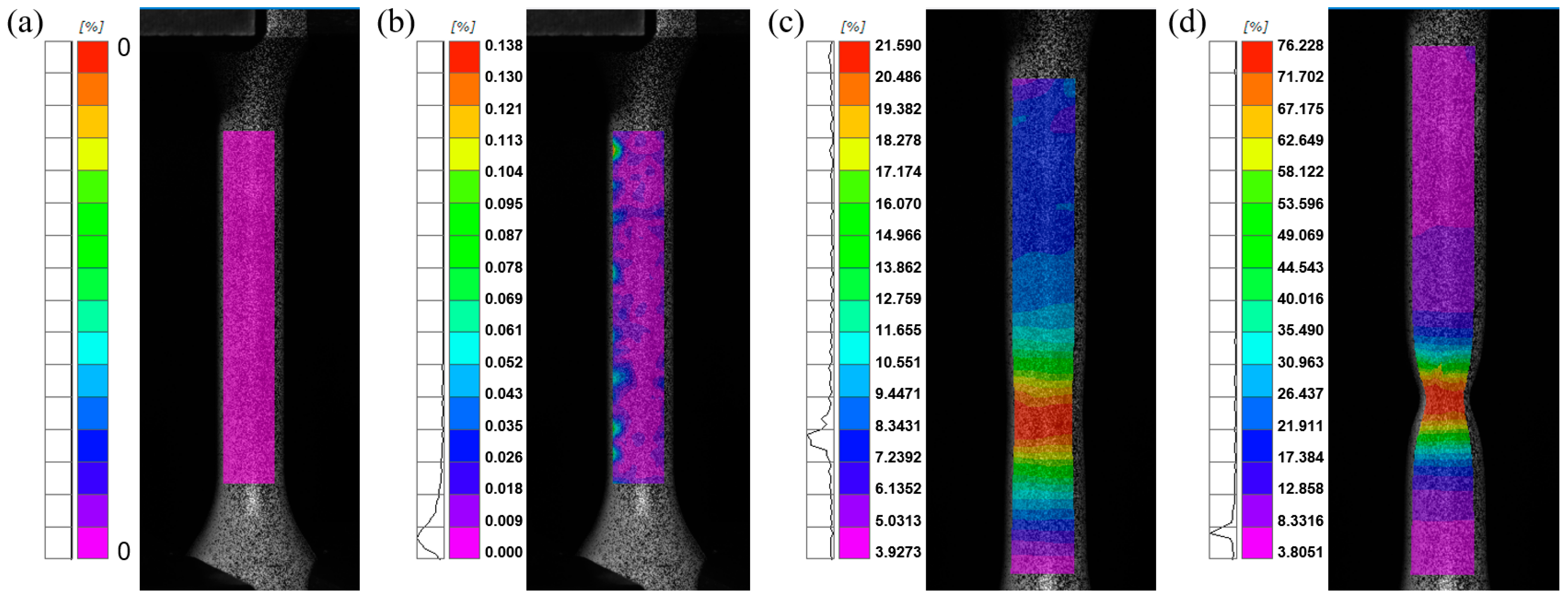
After the tensile experiment and DIC strain test, the strain distribution of the weld round bar tensile specimen was obtained. As shown in Figure 9, at the beginning of the tensile, the deformation of the specimen in the elastic stage tended to be uniform. With the tensile experiment, the specimens gradually showed strain concentration phenomena locally. Subsequently, the specimen underwent necking, and with the rapid increase in deformation in the necking region, the specimen broke at the strain concentration.
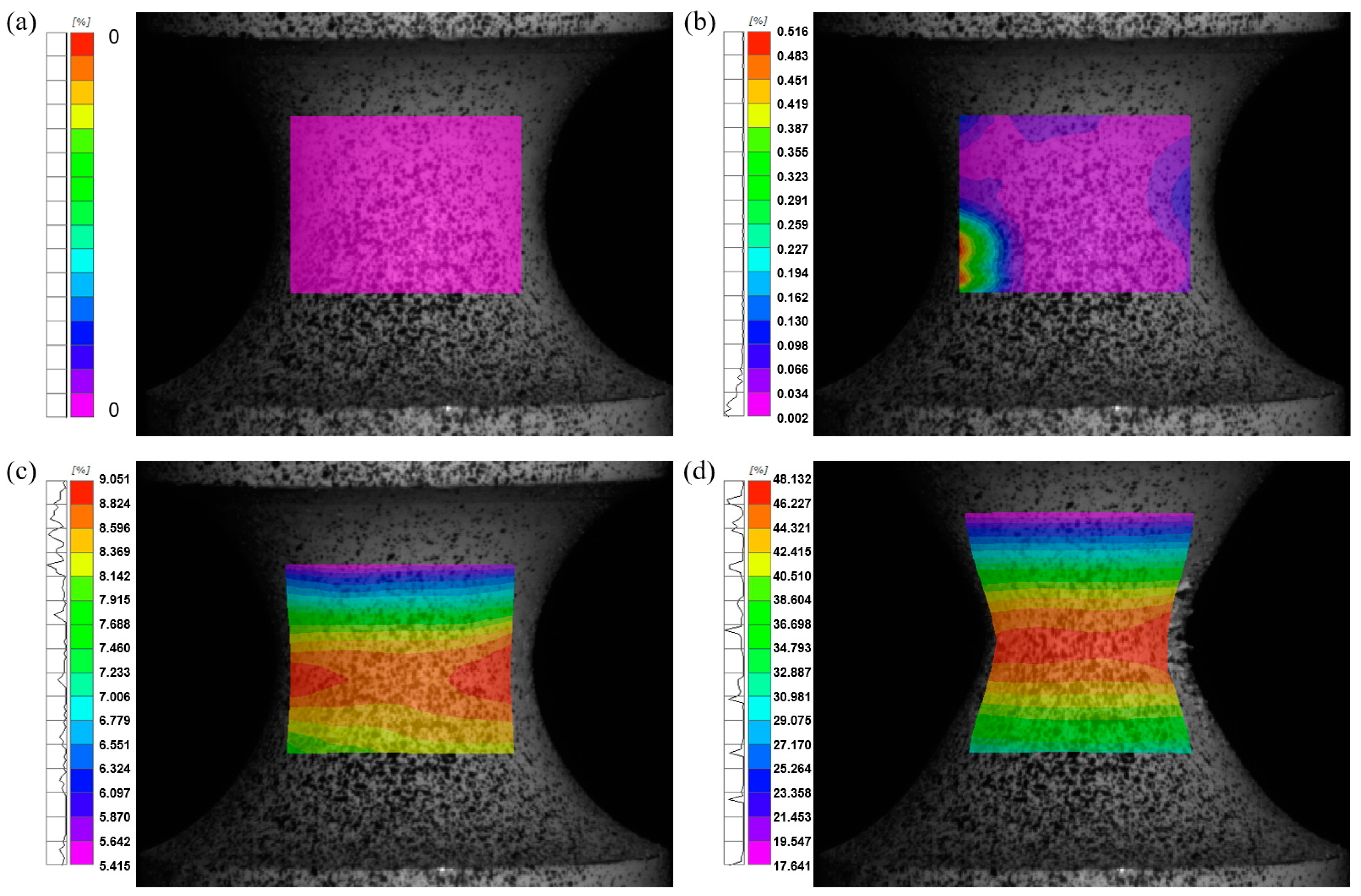
Figure 10, Figure 11 and Figure 12 show the strain distribution of notched tensile specimens for R4, R8, and R12, respectively. As the tensile test proceeded, all specimens showed strain concentration at the notch. Before the necking, the strain changes at both ends of the specimens were approximately symmetrical with the notched centerline as the axis of symmetry. Subsequently, the deformation in the necking region increased rapidly until the specimen fractured at the strain concentration, which indicated that the tensile damage of the weld with notch was a localized damage behavior.
The maximum Mises true strain before failure for the welded round bar was about 76.23%, while the maximum Mises true strain values before failure for the R4, R8, and R12 notched specimens were 48.13%, 54.40%, and 58.43%, respectively.

3.6. Fracture Analysis

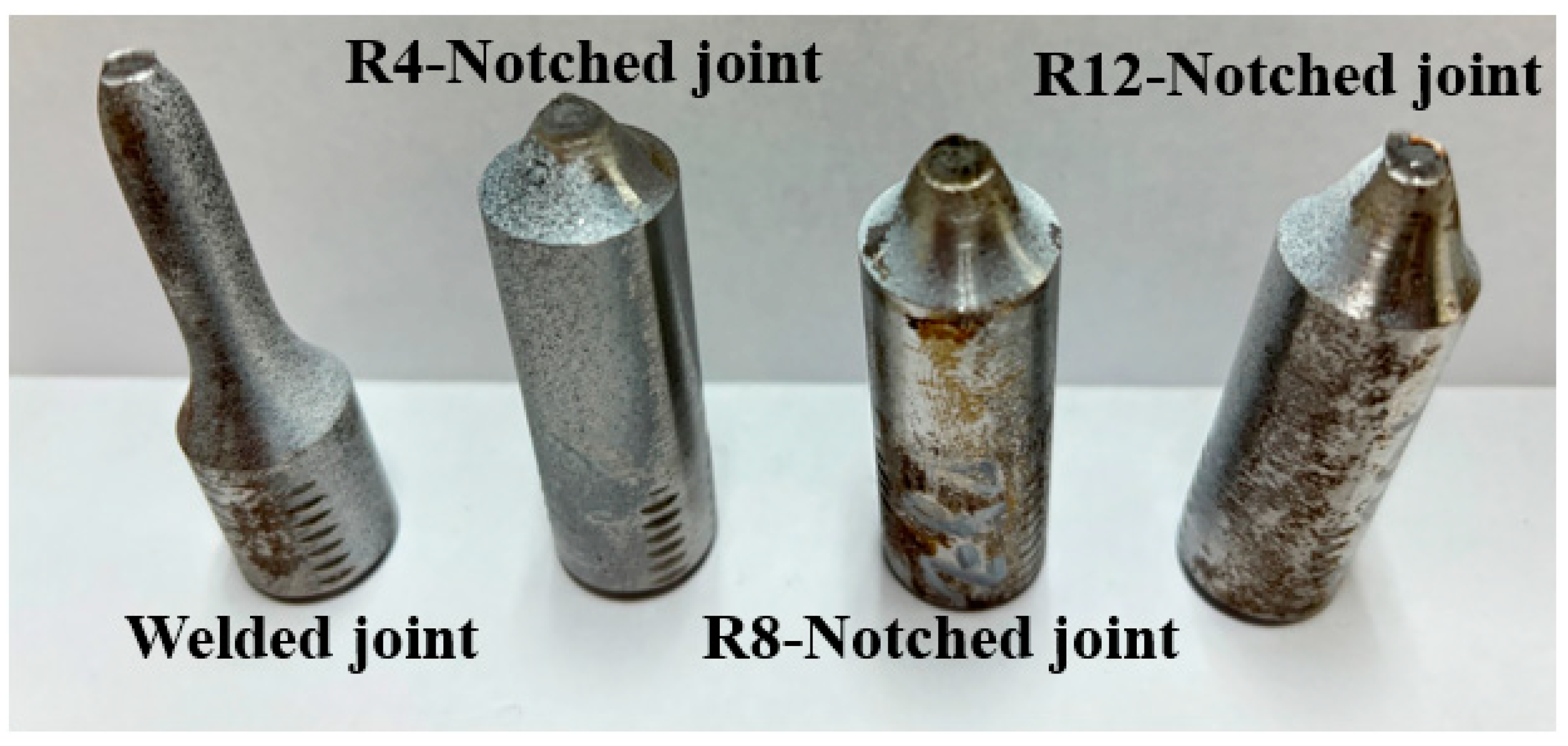
Figure 13 shows the macroscopic fracture morphology of smooth round bar weld specimens and notched specimens of different sizes. The round bar specimen underwent necking, while the notched specimen was not significantly necked.
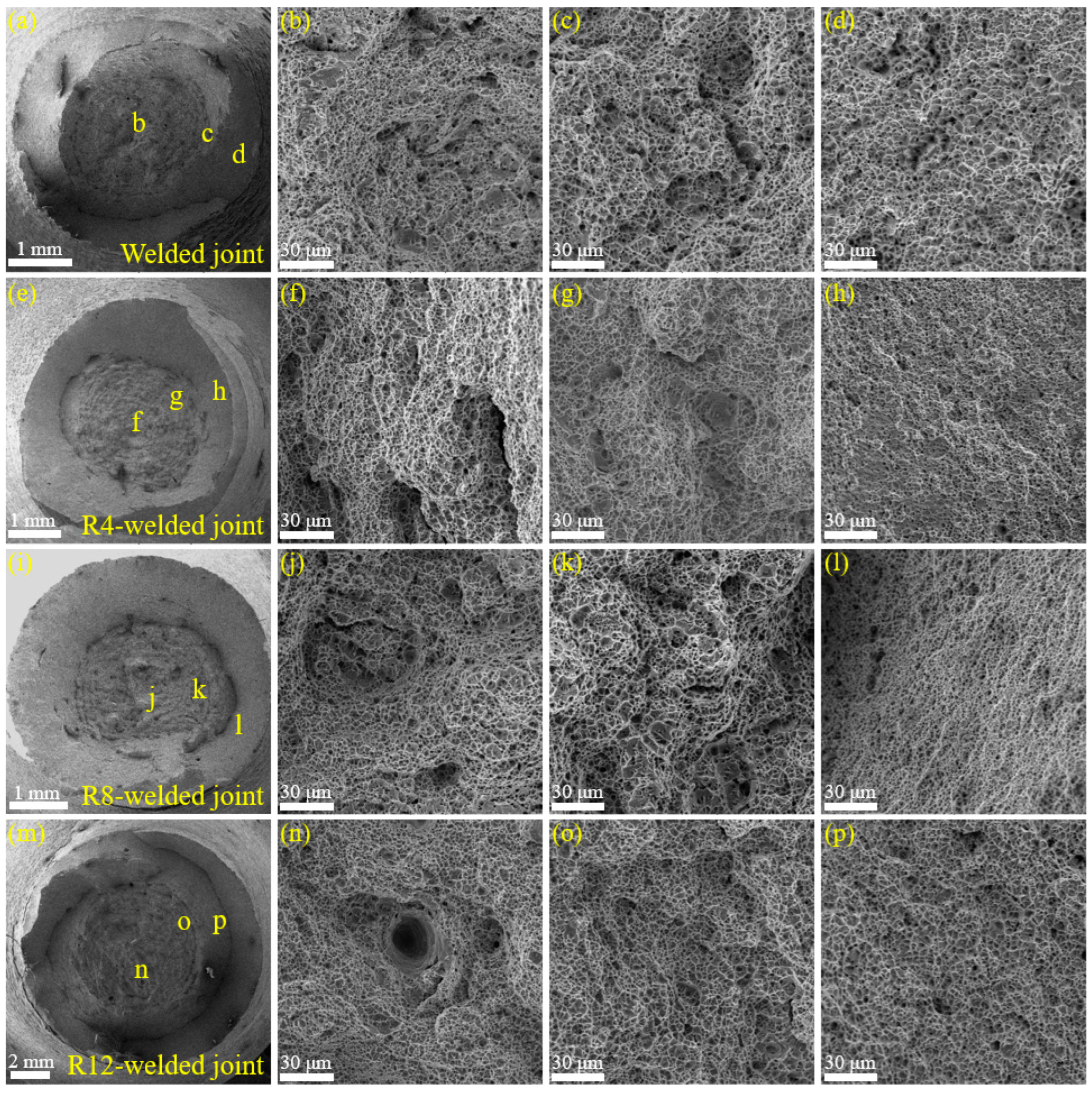
Figure 14a–d show the SEM images of the tensile fracture of the welded round bar specimen, with many dimples distributed at both the edge and the center, which is a typical ductile fracture. However, the dimples at the center were small and deep, while the dimples at the fracture edge region (Figure 14d) were much shallower and tended to be elongated; these were shear dimples. In addition, some smooth features could be seen at the center (Figure 14a), which may have been caused by the inhomogeneous weld organization. Figure 14e–h show the tensile fracture of the R4-notched specimen, and the center of the specimen is a nest-like fracture with normal tensile fracture characteristics, which indicates that the initiation location of the tensile specimen was in the center of the specimen. From the center to the edge, the toughness gradually decreased. In the region of Figure 14h, the dimples decreased, while the tearing ridge was significant, indicating that the plastic deformation of the material in this region was weakened, and it gradually transformed into brittleness. The toughness characteristics of the specimen fracture gradually increased when the notch radius increased to 8 mm and then to 12 mm. Even at the edge of the fracture, many dimples could still be seen, and this feature was closer to the fracture characteristics of welded round bar tensile test.

4. Discussion

(1)
Microstructure and mechanical property relationships
The study presents a comprehensive analysis of the microstructure and mechanical properties of X80 steel welded joints, which are critical for the safe and efficient transportation of oil and gas. The findings reveal distinct variations in hardness levels across different regions of the welded joints. The BM exhibited the highest hardness, attributed to its fine-grained microstructure, while the WZ showed the lowest hardness due to the coarser grain structure and higher ferrite content resulting from the welding thermal cycles. These results align with previous studies that have shown the influence of thermal cycles on the microstructure and properties of welded joints [17,18].
(2)
Impact of notch geometry on fracture behavior
The presence and geometry of notches significantly influenced the fracture behavior of X80 welded joints. Notched tensile tests demonstrated that smaller notch radii led to increased maximum loads but reduced ductility, indicating a pronounced stress concentration effect. This observation is consistent with the theory that notches act as stress concentrators, which can initiate and propagate cracks, leading to a reduction in the load-bearing capacity and ductility of the material [19]. The findings underscore the importance of considering the presence of notches in the design and assessment of pipeline welds to prevent potential failure [19,20].
(3)
Strain distribution and localization
The DIC analysis provided valuable insights into the strain distribution and localization behavior in the weld zone. Larger notches were found to promote more ductile fracture behavior, as evidenced by the increased maximum Mises true strain before failure. This suggests that the size of the notch plays a critical role in determining the balance between the load-bearing capacity and the ductility of the welded joints. The DIC analysis also revealed that strain concentration and localization in the weld zone were highly dependent on notch size, which is a significant factor in the fracture mechanics of pipeline girth welds [21].
(4)
Fracture mode transition
The fracture analysis indicated a transition from ductile to brittle characteristics with decreasing notch radius. The round bar specimen without a notch exhibited substantial necking, a typical indication of ductile fracture. In contrast, the specimens with notches displayed reduced necking, suggesting a transition to a more brittle fracture behavior [22]. This transition is particularly concerning for pipeline integrity, as brittle fractures are more sudden and less predictable, posing a higher risk of catastrophic failure.
(5)
Implications for pipeline integrity
The results of this study have significant implications for the integrity of X80 steel pipelines. The variation in microstructure and mechanical properties across different zones of the welded joint highlights the need for tailored welding practices that can produce more homogeneous joints with improved toughness. The significant influence of notch size on the mechanical properties and fracture behavior further emphasizes the importance of accurate defect characterization and the development of advanced non-destructive evaluation techniques to ensure the long-term safety and reliability of pipelines [23,24].

5. Conclusions

This study investigated the microstructure and mechanical properties of welded joints of X80 steel, particularly in relation to the role of notch geometry. The conclusions drawn from this research are as follows:
(1)
The X80 steel welded joints exhibited distinct hardness levels across different regions, with the BM recording the highest hardness (260 HV) and the WZ showing the lowest (202 HV) due to variations in microstructure influenced by thermal cycles.
(2)
The impact toughness varied significantly, with the base metal demonstrating superior properties compared to the HAZ and the weld zone, which was the least resistant to brittle fracture.
(3)
The presence and size of notches significantly affected the mechanical properties of the welded joints. Smaller notch radii intensified stress concentrations, leading to increased maximum loads but reduced ductility.
(4)
DIC analysis revealed that strain concentration and localization in the weld zone were highly dependent on notch size, with larger notches promoting more ductile fracture behavior (maximum Mises true strain of 58.43% for R12-notched specimens).
(5)
Fracture analysis indicated a transition from ductile to brittle characteristics with decreasing notch radius, underscoring the importance of notch geometry in determining the fracture toughness of X80 steel welds.

Author Contributions

Validation, Y.Z.; Methodology, L.L.; Formal analysis, S.Z.; Investigation, S.X.; Data curation, X.Y. All authors have read and agreed to the published version of the manuscript.

Funding

This research received no external funding.

Data Availability Statement

The processed data required to reproduce these findings cannot be shared at this time as the data also forms part of an ongoing study.

Conflicts of Interest

The authors declare no conflicts of interest.

References

  1. Turichin, G.; Kuznetsov, M.; Sokolov, M.; Salminen, A. Hybrid laser arc welding of X80 steel: Influence of welding speed and preheating on the microstructure and mechanical properties. Phys. Procedia 2015, 78, 35–44. [Google Scholar] [CrossRef]
  2. Wang, C.; Di, X.J.; Dai, L.S.; Han, J.W.; Yang, X.C.; Cui, S.H.; Li, C.N. Intrinsic control mechanism of impact toughness and fracture toughness in X80 pipeline girth weld with heterogeneous microstructure. Mater. Charact. 2025, 219, 114646. [Google Scholar] [CrossRef]
  3. Aydin, H.; Nelson, T.W. Microstructure and mechanical properties of hard zone in friction stir welded X80 pipeline steel relative to different heat input. Mater. Sci. Eng. A 2013, 586, 313–322. [Google Scholar] [CrossRef]
  4. Wang, C.; Di, X.J.; Dai, L.S.; Ma, Y.W.; Han, J.W.; Yang, X.C.; Cui, S.H.; Yu, Y.; Hu, W.Y.; Li, C.N. Correlation between heterogeneous micromechanical properties and fracture toughness in X80 girth weld. Mater. Today Commun. 2024, 41, 110589. [Google Scholar] [CrossRef]
  5. Hu, W.T.; Gong, B.M.; Chang, Q.; Zhao, Z.F.; Dai, L.S.; Liu, Y. Strain fracture behaviors and crack equivalence of X80 welded joints with non-sharp notches at weld root. Int. J. Press. Vessel. Pip. 2024, 214, 105414. [Google Scholar] [CrossRef]
  6. Ning, J.A.; Deng, C.Y.; Wang, Y.J.; Gong, B.M.; Guo, B.C.; Wang, C.; Zhao, N.; Dai, L.S. Stress state analysis of root notch for X80 girth welds with variable wall thickness and misalignment geometric features. Int. J. Press. Vessel. Pip. 2023, 206, 105064. [Google Scholar] [CrossRef]
  7. Zhang, S.C.; Yang, F.L.; Jia, H.D.; Chen, C.C.; Feng, Q.S.; Dai, L.S.; Zhang, Z. Study on the effect of microstructure on toughness dispersion of X70 steel girth weld. Eng. Fail. Anal. 2024, 164, 108671. [Google Scholar] [CrossRef]
  8. Wang, C.; Li, C.N.; Dai, L.S.; Yang, X.C.; Han, J.W.; Cui, S.H.; Yang, Z.W.; Di, X.J. Simultaneously enhancing strength and fracture toughness via tailoring the microstructure in X80 girth weld metal. J. Mater. Res. Technol. 2024, 29, 3096–3107. [Google Scholar] [CrossRef]
  9. Wang, C.; Di, X.J.; Dai, L.S.; Duan, Q.Y.; Han, J.W.; Yang, X.C.; Cui, S.H.; Li, C.N. Effect of grain boundary ferrite morphologies on impact toughness of X80 girth weld. Mater. Lett. 2024, 377, 137412. [Google Scholar] [CrossRef]
  10. Gong, B.M.; Hu, W.T.; Chang, Q.; Zhao, Z.F.; Dai, L.S.; Liu, Y. Transition from ductile to brittle fracture in X80 welded joints with varying notch radii. Int. J. Press. Vessel. Pip. 2023, 212, 105234. [Google Scholar]
  11. Verstraete, M.A.; De Waele, W.; Van Minnebruggen, K.; Hertelé, S. Comparison of girth weld tearing resistance obtained from curved wide plate and single edge notch tensile testing. Eng. Fract. Mech. 2015, 148, 406–420. [Google Scholar] [CrossRef]
  12. Pilkey, W.D.; Pilkey, D.F. Peterson’s Stress Concentration Factors; John Wiley & Sons: Hoboken, NJ, USA, 2007; ISBN 9780470211106. [Google Scholar]
  13. Gao, Z.W.; Wu, S.P.; Xiang, T.; Gong, B.M.; Deng, C.Y. Coupling effect of post-weld heat treatment and fatigue damage on the hydrogen embrittlement of X80 steel welded joints. J. Mater. Res. Technol. 2024, 31, 2646–2657. [Google Scholar] [CrossRef]
  14. Zhu, L.X.; Luo, J.H.; Jia, H.D.; Li, L.F.; Yu, W.C.; Chen, Y.N. Effect of deviation of welding parameters on mechanical properties of X80 steel girth weld. J. Mater. Res. Technol. 2023, 22, 3311–3318. [Google Scholar] [CrossRef]
  15. Bai, F.; Ding, H.S.; Tong, L.G.; Pan, L.Q. Microstructure and properties of the interlayer heat-affected zone in X80 pipeline girth welds. Prog. Nat. Sci. Mater. Int. 2020, 30, 110–117. [Google Scholar] [CrossRef]
  16. Xu, K.; Qiao, G.Y.; Shi, X.B.; Xiao, F.R. Effect of stress-relief annealing on the fatigue properties of X80 welded pipes. Mater. Sci. Eng. A 2021, 807, 140854. [Google Scholar] [CrossRef]
  17. Salminen, A.; Turichin, G.; Kuznetsov, M.; Sokolov, M. Influence of welding parameters on the microstructure and mechanical properties of X80 steel girth welds. Weld. World 2016, 60, 345–356. [Google Scholar]
  18. Wang, C.; Di, X.J.; Dai, L.S.; Han, J.W.; Yang, X.C.; Cui, S.H.; Li, C.N. Microstructural evolution and mechanical properties of X80 pipeline steel girth welds under different welding conditions. Mater. Sci. Eng. A 2023, 805, 139854. [Google Scholar]
  19. Kocak, M.; Yildiz, T. Effect of notch geometry on the fracture behavior of welded joints in X80 pipeline steel. Eng. Fract. Mech. 2017, 175, 12–23. [Google Scholar]
  20. Gong, B.M.; Hu, W.T.; Chang, Q.; Zhao, Z.F.; Dai, L.S.; Liu, Y. Fracture behavior of X80 welded joints with different notch geometries. Int. J. Press. Vessel. Pip. 2022, 210, 105214. [Google Scholar]
  21. Hertelé, S.; Verstraete, M.A.; De Waele, W.; Van Minnebruggen, K. Strain distribution and localization in X80 pipeline girth welds under tensile loading. Eng. Fract. Mech. 2016, 155, 123–134. [Google Scholar]
  22. Viloria, A. Microhardness profile and residual stresses evaluation in a shot peened SAE 5160H steel. Rev. UIS Ing. 2024, 23, 103–114. [Google Scholar]
  23. Wang, C.; Di, X.J.; Dai, L.S.; Han, J.W.; Yang, X.C.; Cui, S.H.; Li, C.N. Tailored welding practices for improved toughness in X80 pipeline girth welds. Mater. Sci. Eng. A 2024, 807, 139876. [Google Scholar]
  24. Midawi, A. Characterization of local mechanical properties of X80 pipeline girth welds using advanced techniques. In Proceedings of the 2016 11th International Pipeline Conference, Calgary, AB, Canada, 26–30 September 2016; Volume 3: Operations, Monitoring and Maintenance; Materials and Joining. American Society of Mechanical Engineers: New York, NY, USA, 2016. [Google Scholar]
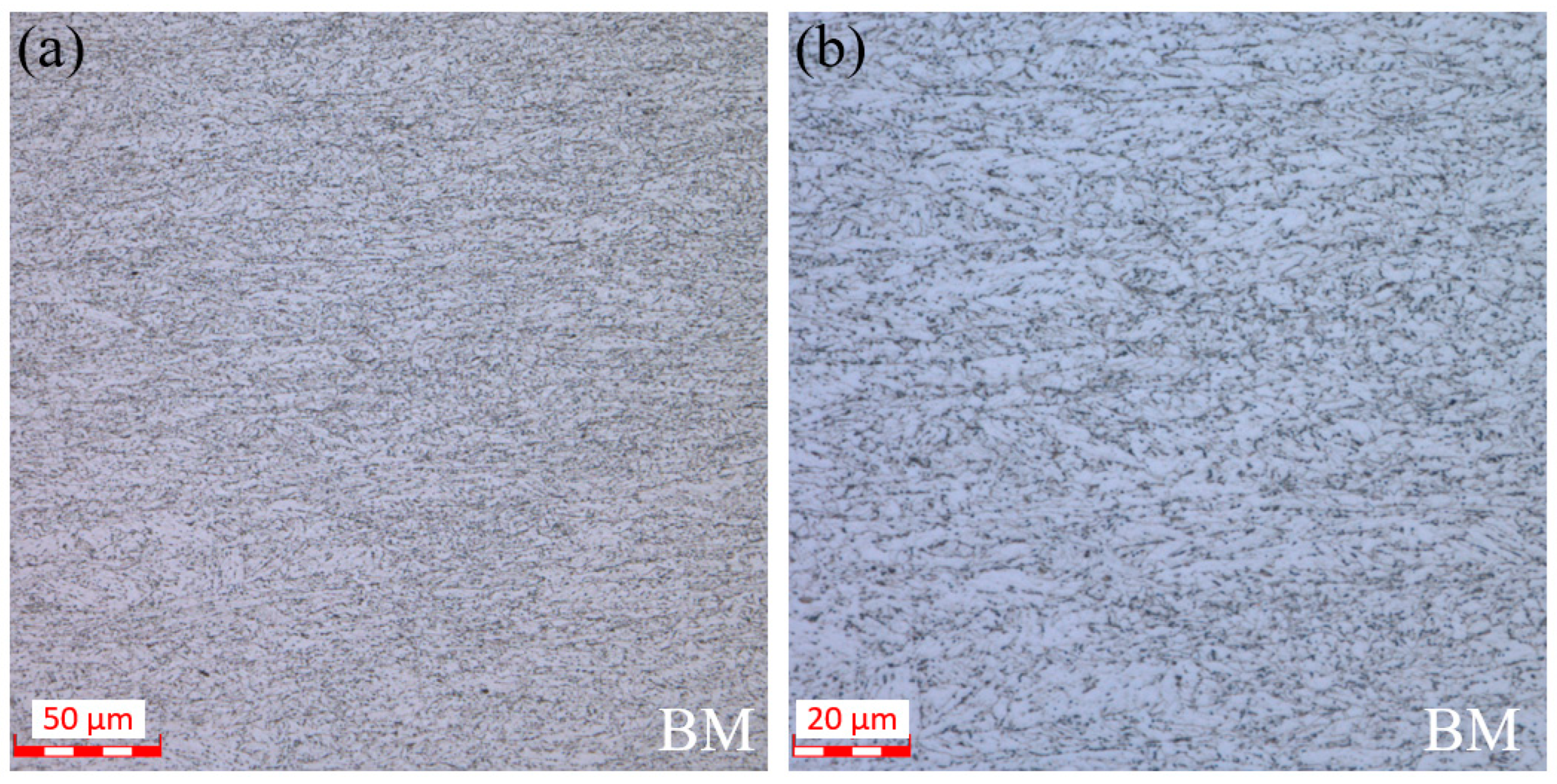
Figure 1. Microstructure characteristics of X80 (BM): (a) 500× magnification, (b) 1000× magnification.
Processes 13 00763 g001
Figure 2. Dimensions of the full weld specimens: (a) smooth, (b) notched.
Processes 13 00763 g002
Figure 3. Tensile testing equipment and DIC measuring system: (a) tensile machine and camera system, (b) testing process, (c) prepared specimen.
Processes 13 00763 g003
Figure 4. Microstructures of different zones in the cross-section of welded joint: (a) overall microstructure of the joint, (b) enlarged view of area b, (c) enlarged view of area c, (d) enlarged view of area d, (e) enlarged view of area e, (f) enlarged view of area f, (g) enlarged view of area g, (h) enlarged view of area h, (i) enlarged view of area i.
Processes 13 00763 g004
Figure 5. Hardness distribution at different locations (upper, middle, lower).
Processes 13 00763 g005
Figure 6. Impact properties of welded joints in different characteristic zones.
Processes 13 00763 g006
Figure 7. The load–displacement curve.
Processes 13 00763 g007
Figure 8. True stress–strain curve (R represents the direction of diameter, L represents the axial direction).
Processes 13 00763 g008
Figure 9. Strain contours of smooth round bar specimens in different stages (axial direction): (a) initial, (b) elastic stage, (c) local necking, (d) near fracture.
Processes 13 00763 g009
Figure 10. Strain contours of R4 notched specimens in different stages (axial direction): (a) initial, (b) elastic stage, (c) onset of local necking, (d) near fracture.
Processes 13 00763 g010
Figure 11. Strain contours of R8 notched specimens in different stages (axial direction): (a) initial, (b) elastic stage, (c) onset of local necking, (d) near fracture.
Processes 13 00763 g011
Figure 12. Strain contours of R12 notched specimens in different stages (axial direction): (a) initial, (b) elastic stage, (c) onset of local necking, (d) near fracture.
Processes 13 00763 g012
Figure 13. Macroscopic fracture of different welded joints.
Processes 13 00763 g013
Figure 14. Morphologies of welded joints: (ad) normal joint, (eh) R4-notched joint, (il) R8-notched joint, (mp) R12-notched joint.
Processes 13 00763 g014
Table 1. Nominal chemical composition of X80 steel (wt.%).
CSiMnPSCrMoNiNbVTiCuAl
0.050.211.840.0130.0020.280.280.0560.0780.0260.0160.0620.033
Disclaimer/Publisher’s Note: The statements, opinions and data contained in all publications are solely those of the individual author(s) and contributor(s) and not of MDPI and/or the editor(s). MDPI and/or the editor(s) disclaim responsibility for any injury to people or property resulting from any ideas, methods, instructions or products referred to in the content.