Article

Combined Cycle Gas Turbine System with Molten Salt Energy Storage: Peak Regulation and Flexibility

1
Department of Energy and Power Engineering, Northeast Electric Power University, Jilin 132012, China
2
State Grid Jilin Electric Power Research Institute, Changchun 130021, China
3
Economic and Technological Research Institute of State Grid Jilin Electric Power Co., Ltd., Changchun 130021, China
*
Author to whom correspondence should be addressed.
Processes 2025, 13(3), 604; https://doi.org/10.3390/pr13030604
Submission received: 15 January 2025 / Revised: 16 February 2025 / Accepted: 19 February 2025 / Published: 20 February 2025

Abstract

:
With the increase in the amount of new energy in new power systems, the response speed of power demand changes in combined cycle gas turbines (CCGTs) is facing new challenges. This paper studies an integrated operation strategy for the coupled molten salt energy storage of CCGT systems, and analyzes the system through simulation calculation. The advantages of the coupled system are determined by comparing the electrical output regulation capability, thermoelectric ratio, gas consumption rate, and peaking capacity ratio. In addition, using stored energy to maintain the temperature of the heat recovery steam generator (HRSG) can shorten the system’s restart time, improve the unit’s operating efficiency, and reduce the start-up cost. Our findings can be used as a reference for accelerating the performance improvement of CCGT systems, which is also crucial in technologies for waste heat recovery, molten salt energy storage technology, and promoting the sustainable development of energy systems.

1. Introduction

CCGT units have received widespread attention due to their significant advantages in improving the electricity supply’s cleanliness and enhancing the power system’s flexibility [1,2]. These units can not only effectively improve energy utilization efficiency but also play an essential role in peak regulation [3,4], especially in the context of the increasing demand for renewable energy, such as wind energy and photovoltaic energy [5,6,7]. It is vital to study the performance of CCGT units. Many scholars have studied the performance improvement of CCGT systems.
Kamal et al. [8] utilized theoretical modeling and simulation analysis to thoroughly investigate the impact of enhancing gas turbine flexibility on the performance of CCGTs. The modeling analysis concluded that the extension of the minimum environmental load (MEL) results in the overall improvement of the gas turbine in the CCGT being limited to 19%. Meanwhile, the acceleration rate achieved a significant improvement of 51% through air injection. This innovatively reveals that these flexibility improvements have a positive impact on the overall performance of the CCGT.
Polyzakis et al. [9] conducted a study on the performance of various gas turbine cycles in a combined cycle power plant through theoretical analysis and simulation experiments. They found that the reheat cycle gas turbine exhibited the highest efficiency, with a design-point combined cycle efficiency of 53.5%. Furthermore, they proposed an optimization scheme, which offers a scientific foundation and practical innovation for optimizing the gas turbine cycle.
Liu et al. [10] conducted a systematic analysis of the relative deviations in operating parameters of the high-pressure steam turbine (HPST), intermediate-pressure steam turbine (IPST), and low-pressure steam turbine (LPST) within natural gas combined cycle (NGCC) systems across various operating conditions. They achieved an enhancement in system performance through an optimization strategy and obtained quantitative results regarding the relative deviations in specific operating parameters. These findings offered an innovative optimization scheme for enhancing energy efficiency and promoting environmentally friendly operation in the NGCC system.
Sylwia et al. [11] developed a thermodynamic and economic model for a CCGT and compressed air energy storage (CAES) system, providing an in-depth evaluation of the system’s potential to enhance power generation flexibility. Through specific case studies and simulations, it was discovered that, while technical validation indicates the theoretical feasibility of integration, under current market conditions, an integrated system is not economically viable, even with an energy storage efficiency of 81%. This is because the net profit does not offset the additional investment costs. This finding offers innovative insights into the economic challenges faced by integration projects and suggests potential solutions, such as participation in the ancillary services market.
Yang et al. [12] developed a detailed operating condition analysis model for a gas–steam combined cycle cogeneration unit. They used the step-by-step superposition method for the compressor and turbine and a modularized variable operating condition characterization method for the HRSG. A 390 MW pumped-condensate cogeneration unit was analyzed, showing a power peaking depth of 31.23% and fuel cost yield under full operating conditions. The study found that the unit’s peaking economics are more favorable when the design’s heat-to-power ratio exceeds 0.2, but diminish when the ratio is lower. The method reveals the peak shifting capacity and economic benefits of GTCC cogeneration units, aiding operational decision-making. However, the model’s complexity requires optimization to improve computational efficiency.
Bălănescu et al. [13] investigated adding an organic Rankine cycle (ORC) unit to a gas–steam combined cycle power plant to recover waste heat. The study found that integrating an ORC unit downstream of the gas turbine can increase the plant’s overall efficiency by about 1.1%, saving around 56,000–57,000 m3 of natural gas and up to EUR 16,000–16,500 annually. This method reduces operating costs and greenhouse gas emissions more effectively than traditional waste heat recovery methods. However, further techno-economic studies are needed to confirm its feasibility, and its widespread adoption requires considering the complexity and maintenance costs of the ORC system.
Barelli et al. [14] analyzed the integration of an additional compressor-stage supercharged gas turbine into a conventional NGCC using a 0-D model simulation. The study found that a supercharged natural gas combined cycle (SNGCC) significantly improved efficiency under partial loads. For example, at 70% rated power, the SNGCC consumed 5.9% less natural gas than NGCC and maintained 49% efficiency even at a low load of 47.8%. This technology enhances plant flexibility and energy savings but requires additional investment, equipment modification, and optimization of variable-speed compressors.
Vahab et al. [15] applied four robust control strategies, namely H2, H, H2/H, and μ synthesis, to control the speed and temperature of a V94.2 gas turbine in a combined cycle power plant. Various controllers were designed and simulated, utilizing the linear model derived from real-time gas turbine data. It was found that all control strategies exhibited robust stability under model uncertainty and load variation, albeit with slight differences in performance. Among these, the H controller demonstrated the best performance for speed control, whereas the μ-synthesis controller proved superior for temperature control. This research presents innovative control strategy options for industrial applications, yet it also reveals that compromises must be made between design goals and control requirements.
Liu et al. [16] introduced a new strategy called EGR-IGVC to improve the efficiency of CCGT plants under part-load conditions. By recycling some exhaust gases from the heat recovery steam generator (HRSG) and adjusting the inlet guide vanes (IGVs), this strategy increases CCGT efficiency by up to 1.2% and reduces CO2 emissions by up to 13.8 kg/MW·h. Compared to the traditional IGVC strategy, exhaust gas recycle–inlet guide vane control (EGR-IGVC) shows significant benefits, despite potential drawbacks in gas turbine operation. However, its application is limited by the maximum exhaust gas recirculation rate (EGRR), and its pros and cons need careful assessment in real-world use.
Molten salt energy storage technology has many advantages, and its applications in various fields have attracted widespread attention. Integrating this technology into systems for optimization can effectively address the consistency issues between the supply side and the demand side of thermal energy in terms of time and space. It can also enhance the flexibility and stability of the new energy system and improve the overall energy utilization efficiency.
Zhou et al. [17] studied heat transfer between high-pressure air and molten salt in a solar-assisted compressed air energy storage system. Results show a 92% heat transfer efficiency under specific conditions. Molten salt effectively absorbs and stores compression heat, improving system energy efficiency by 15%. Compared to traditional systems, it offers advantages in heat recovery and utilization, enhancing stability and economy. However, it faces challenges such as higher corrosiveness, increased complexity, and elevated maintenance costs.
Xue et al. [18] studied a 1.05 MW molten salt furnace for waste heat transfer and storage of blast furnace gas. Their results showed a waste heat recovery efficiency of up to 90% and a heat transfer efficiency of 77.12%, improving utilization and storage capacity. Compared to conventional systems, it offers higher flexibility and reliability. However, drawbacks include higher initial costs and stringent operation/maintenance requirements. In conclusion, the proposed all-condition thermal energy storage technology for molten salt furnaces is an innovative solution with considerable application prospects.
Burcu et al. [19] assessed a molten salt packed bed thermal energy storage system using experimental and numerical methods, with three waste materials as fillers. The system achieved a maximum thermal energy storage efficiency of 95% under specific conditions and exhibited high thermal stability. Compared to conventional systems, it is cost-effective, environmentally friendly, and efficient. However, waste material fillers may present compatibility and long-term stability challenges. The study offers novel insights, but further exploration of material selection and system optimization is needed for practical use.
Shuai et al. [20] utilized porous silicon carbide ceramics compounded with solar salts to prepare composite phase change materials, and experimentally and computationally verified their superior thermal conductivity properties. The results show that the maximum temperature difference of the composites is reduced by 18 °C, the phase transition rate is increased by 42.9%, and the ceramics remain stable in corrosive environments, providing a new durability solution for medium-to-high-temperature thermal energy storage.
Appasaheb et al. [21] studied a latent heat energy storage system with fins in a solar thermal power plant using numerical simulation and experiments. They found that optimizing the number and thickness of fins increased the system’s discharge efficiency by 4.5%, reaching 90.59% in the first cycle. The study also developed a simplified thermal resistance model to analyze the system’s performance and integrated it into the overall power plant model for transient analysis, highlighting the importance of fins in extending continuous power generation time and improving melting fraction.
Qijun et al. [22] utilized the Dymola platform to develop a dynamic model of a 600 MW subcritical coal-fired power plant, which incorporated a molten salt thermal energy storage subsystem. They then assessed its peaking capacity and economic viability through simulations of various charging and discharging processes. The integration of a molten salt thermal energy storage system was found to enhance the peaking potential of the power plant during charging and discharging processes, reaching 12.83% and 6.86% of the rated power, respectively. Additionally, the maximum peaking rate achieved was up to 9.27% Pe/min and 5.11% Pe/min, resulting in a significant improvement in peaking flexibility. Furthermore, the system proposed in this paper is economically viable. Despite the significant initial investment, the levelized delivered cost of USD 151.29/MW·h is deemed acceptable, given its crucial role in peaking demand and the potential for government subsidies.
Soto et al. [23] utilized an integrated nuclear and solar system that shares molten salt thermal energy storage to enhance the flexibility and reliability of the overall energy system. Through optimizing the system design and operation strategy, they aimed to improve the energy efficiency and economy of the entire system. This integrated system is capable of providing additional power during peak demand periods while utilizing surplus heat for energy storage during low demand periods, thereby increasing system flexibility and promoting the penetration of renewable energy. This integrated approach effectively harnesses the advantages of nuclear and solar energy to enhance overall system performance, yet it also necessitates addressing issues pertaining to system optimization, economic analysis, and grid integration.
Assareh et al. [24] studied a concentrated solar power (CSP) cogeneration system with MSES and HRSG using modeling and simulation. Their results showed up to a 15% energy efficiency gain and a 12% CO2 reduction in case studies in the US, France, and Canada. MSES integration boosts systems’ peaking capability and flexibility. HRSG recovers waste heat, further enhancing efficiency. However, limitations include high initial investment and the need for MSES heat loss optimization. Overall, the CSP system with a multistage steam expansion system (MSES) and an HRSG is an innovative solution for solar energy use and carbon reduction.
Decai et al. [25] conducted an investigation on the feasibility of integrating a cascaded latent heat storage (CLHS) system into a 420 MW CCGT power plant. They employed a dynamic modeling and simulation methodology, which was based on Aspen Plus software V11 combined with an external FORTRAN code. The simulation results indicate that the integration strategy is technically feasible, and the scheme has the potential to significantly enhance the flexible operation capability of the power plant. Furthermore, the steam turbine in load-following operations is able to respond to load changes within a 6 min timeframe, facilitating fast energy dispatch and optimization of energy storage efficiency. This provides an innovative solution for enhancing the flexibility of CCGT power plants.
Jacek et al. [26] integrated an adiabatic compressed air energy storage (ACAES) system with a CCGT power plant, utilizing numerical simulations to enhance the overall operational flexibility of the system. The results indicate that the integrated system significantly lowers the minimum load level and enhances peak power, with an efficiency loss of only 2%. Additionally, an innovative integrated concept is presented, utilizing the CCGT compressor as the primary compression component for the ACAES system.
Although research on molten salt energy storage technology is maturing and its integration to enhance system flexibility is widely studied, there is still a lack of studies on its impact when coupled with CCGT systems, particularly regarding deep peaking capability and operational flexibility. Additionally, unresolved issues in system integration and control strategies limit the widespread application and promotion of this coupling. Therefore, this paper utilizes the power station thermal system calculation software EBSILON 16.0 (Shanghai Feiyi Software Technology Co., Ltd., Shanghai, China) to design the operation mode of the aforementioned coupled system and analyze its performance. By adjusting the operational strategy of the heat storage device during peak and valley periods, the study aims to enhance the unit’s economy and reliability, facilitate flexible operation and deep peaking, and ultimately improve energy efficiency and support system sustainability.
The main sections of the paper are as follows:
(1)
An F-class CCGT system and its coupled molten salt energy storage system were designed and established by using the power station thermal system calculation software EBSILON 16.0. At the same time, an integrated operation strategy for the CCGT system’s start-up, standstill operation, and load-following operation coupled with a molten salt energy storage device was proposed.
(2)
The performance of the coupled system was evaluated comprehensively by calculating the electrothermal characteristics, electrical output regulation capability, and thermal performance evaluation of systems. In addition, the advantages of the coupled system were determined through comparison with the F-class CCGT system.
(3)
The conclusions accelerate the performance improvement of the CCGT system, including the improvement of the generating capacity of the unit, the enhancement of the system peak load balancing capacity, and the improvement of the system heating capacity. Additionally, the economy of the system under different heat loads is analyzed.

2. Modeling of Systems

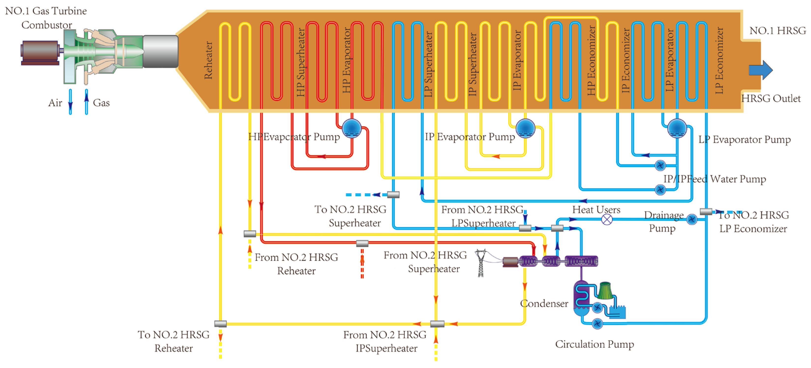
2.1. Description of CCGT System

An F-class CCGT system was used for this study, which generally consists of two gas turbines, one steam turbine, and two HRSGs, as shown in Figure 1. The thermal system is mainly composed of a gas circulation system, HRSG, and steam water system. The gas turbine serves as the system’s core, and its exhaust gas is used to heat water in the HRSG to produce steam. Table 1 lists the parameters of the gas turbine, steam turbine, and HRSG.
When electricity demand is low, reducing the load of a gas turbine or shutting it down can reduce the amount of electricity generated, while the HRSG heating is unaffected. A low-pressure economizer recirculation system was designed to avoid the problem of flue gas corrosion at low loads. The water supply system is divided into two parts to ensure the use of water under different pressures. Table 2 gives the performance and major techno-economic indexes of combined cycle gas turbine units.

2.2. Description of Molten Salt Energy Storage Coupled with CCGT System

The molten salt energy storage coupled with the CCGT system is shown in Figure 2. In the coupled system, the gas turbine, HRSG, steam turbine, and generator are the core equipment of the CCGT system, which together constitute the power generation and heating basis of the system. A concentric tubular cascade phase change accumulator absorbs and releases heat along the flow direction of the heat transfer fluid with different layers of high-temperature nitrate phase change materials. As a result, the gas turbine in the system runs in the same state while starting the molten salt energy storage device to store excess energy in the case of reduced heating demand. In contrast, when the heating demand increases, the molten salt energy storage system releases the previously stored energy to meet the increased heating demand. This energy storage and release process makes the entire system more flexible in the face of fluctuations in heating demand, improving the adaptability and stability of the system. Table 3 gives the physical and thermal characteristics of PCM.
During the start-up process, valves No. 1 and 3 are opened while valves No. 2 and 4 are closed. The exhaust gas in the HRSG is controlled by adjusting the exhaust gas baffle at the gas turbine outlet. In this process, the wasted gas heat discharged into the atmosphere can be recovered by the molten salt heat storage device for rapid load increase or heating purposes. During the load-following process, the No. 1 and No. 3 valves are kept open while the No. 2 and 4 valves are closed. The storage device energy can heat the ambient air to maintain the temperature of the metal parts in the HRSG, which makes it possible to release the unit quickly. As a result, this operation generally allows for the shutting down of gas and steam turbines while facilitating a quick restart. As for the load-following process, it is necessary to close the No. 1 and No. 3 valves and open the No. 2 and No. 4 valves. By adjusting the opening of the exhaust throttle valve at the gas turbine outlet, the inlet gas volume in the storage device and the HRSG is adjusted to adjust the amount of steam produced by the HRSG.
Under the electric load period, the electric power of the steam turbine is reduced by reducing the exhaust gas in the HRSG, and the minimum power operation is realized. At this time, energy storage can also be carried out by increasing the air used in the energy storage device. In this way, the gas turbine can still operate under the rated load state, and the operation efficiency of the system is improved. While under the peak condition of electric load, part of the water supply in the low-pressure drum will absorb the heat in the energy storage device and form high-temperature steam, which will enter the steam turbine’s medium-pressure cylinder or low-pressure cylinder to carry out work. Finally, the above operation makes it possible to increase the electric power of the unit rapidly. In addition, the decrease in steam flow at the inlet of the low-pressure cylinder during the trough of the electric load will directly affect the heat supply, which can be supplemented by releasing energy from the heat storage device. The realization of stable heating in the trough of the electric load will further enhance the economic benefits of the unit.

2.3. Modeling and Verification of the CCGT System

EBSILON 16.0 software was employed to model the CCGT units [28]. Through parametric modeling, a complete thermodynamic system model can be achieved. Additionally, the software supports the simulation of dynamic characteristics of the CCGT system, including start-up, standstill operations, and load-following processes. The necessary pressure drop modes are as follows: For the condenser, the main pressure drop parameter DP12N is set to 0.05, and the secondary pressure drop parameter DP34RN is set to 0. As for the evaporator, its pressure drop parameter DP34RN is also set to 0. Regarding the heat exchanger, the pressure drop parameter DP12RN is set to 0.005, while the pressure drop parameter DP34RN is configured as 0.0002. During the research process, the heat losses caused by reasons such as heat conduction, heat convection, and thermal radiation during operation are not taken into account.

2.3.1. Modeling of Steam Turbine Subsystem

The turbine stage group component forms the turbine model through the interconnection of stage group components in accordance with the steam–water flow process. The efficiency of this turbine stage group is determined based on isentropic efficiency calculations. Once the design base case has been established, the off-design conditions can automatically inherit the stage efficiency derived from the preceding condition. A schematic diagram of the steam turbine component is illustrated in Figure 3, where 1 represents the steam inlet, 2 represents the steam outlet, 3 represents the drive shaft inlet, and 4 represents the drive shaft outlet.
The characteristic relationships between the pressure, p; temperature, T; mass flow rate under the design condition, GN; and mass flow rate, G, under off-design conditions can be calculated using the Froude formula [29].
G G N = p 1 p 2 p 1 N p 2 N T 1 N T 1
where p1N and p2N are the inlet and outlet pressures of the stage group under design conditions. T1N is the inlet temperature of the stage group under design conditions. T1 is the inlet temperature of the stage group under off-design conditions.

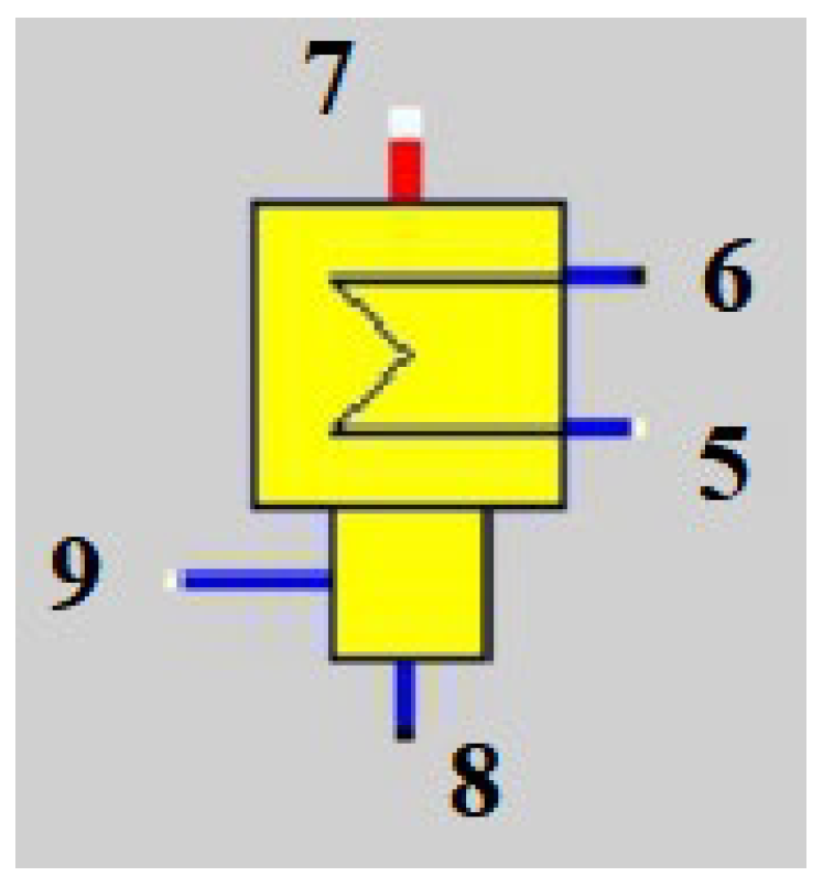
2.3.2. Modeling of Steam Turbine Condenser

The condenser component functions as the cooling device in a condensing steam turbine system. It facilitates heat exchange between the exhaust steam from the low-pressure cylinder and external cooling water, thereby condensing the end-stage exhaust steam into water. This component is crucial for establishing and maintaining a vacuum at the rear of the steam turbine. During simulation, the outlet parameters of the cooling water are determined using a heat balance approach. A schematic diagram of the condenser component is illustrated in Figure 4.
The module has 10 initial parameters: cooling water inlet pressure p5, cooling water outlet pressure p6, turbine extraction inlet pressure p7, turbine extraction outlet pressure p8, drain inlet pressure p9, cooling water inlet mass flow rate M5, cooling water outlet mass flow rate M6, steam extraction mass flow rate M7, condensate outlet mass flow rate M8, and drain outlet mass flow rate M9 [30].
p 6 = p 5 D p 56 N p 8 = p 7 D p 78 N p 9 = p 7
M 6 = M 5 M 8 = M 7 + M 9

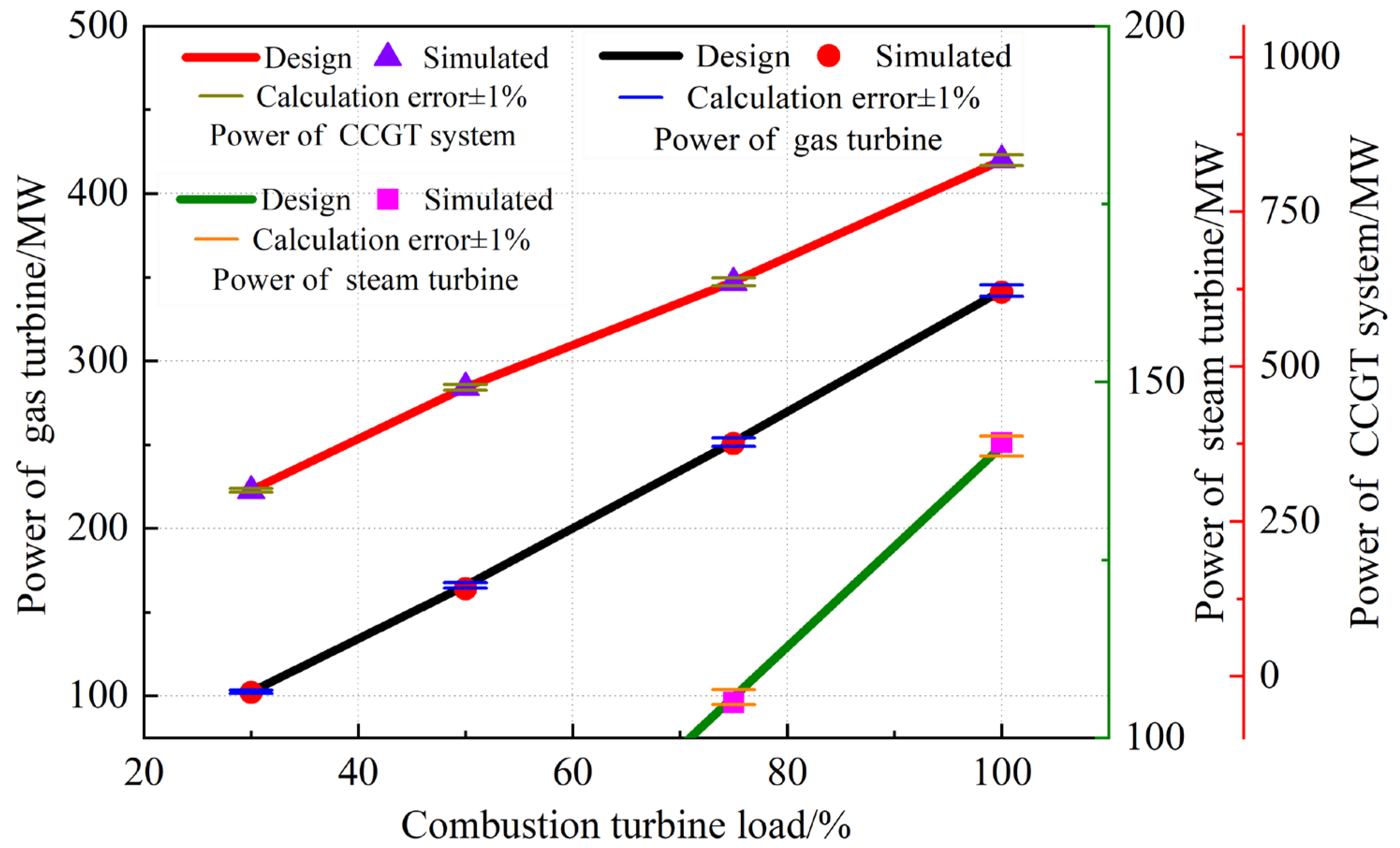
2.3.3. Verification of the Model

The unit is operated in pumping mode, and the minimum gas turbine load rate is set to the 30% turbine heat acceptance (THA) operating condition to ensure stable operation under low load conditions. At the same time, the maximum heating load flow of the unit is set to 140 t/h to ensure the stability and safety of the final stage blade of the turbine. The electric heating characteristic curves of the units under 100% THA, 75% THA, 50% THA, and 30% THA operating conditions are shown in Figure 5.
In addition, it can be seen from the electric heating characteristic curve in Figure 5 that with the increase in the heating load, the power generation will decrease accordingly. When the heating load is constant, increasing the gas turbine load rate can increase the power generation. The maximum heating capacity of the unit is limited by the minimum cooling flow of the low-pressure cylinder of the turbine because of the safety hazard caused by overheating the blades or other potential safety hazards when the minimum cooling flow is insufficient.
Figure 6 shows a comparison between the simulation calculation results and the design parameters to verify the accuracy of the simulation calculation results. The results show that the simulated values of gas turbine power, steam turbine power, and combined cycle unit power are consistent with the design values, and the calculation error is controlled within 1%. The accuracy of the model established in this paper and the reliability of using this model to calculate the variable operating conditions of the unit are explained.

3. Results and Discussion

As an essential part of the coupled system, the performance parameters of the molten salt energy storage device have a necessary impact on the system’s overall operating efficiency and peak regulation capacity. The theoretical maximum energy storage capacity of this paper’s molten salt energy storage device is 315 MW, and the energy storage efficiency is 78%. The actual maximum energy supply can be calculated using Equation (4).
η = Q a c t , max Q t h e o , max
where Qact,max is the actual maximum energy supply, Qtheo,max is the theoretical maximum energy storage, and η is the efficiency of energy storage. As a result, the actual maximum energy supply of the energy storage device is 245.7 MW [31].

3.1. Entropy Change and Thermal Efficiency of System

In the results output of EBSILON, the entropy of each component can be obtained. Through further calculations, the entropy changes for each component can be derived, as shown in Table 4.
It is clear that the entropy change for the gas turbine, steam turbine, and HRSG is positive, which indicates that each component is an irreversible process. This result is consistent with the First and Second Laws of Thermodynamics.
In addition, the thermal efficiency of the CCTG system before and after coupling with the molten salt energy storage system is 51.2% and 52.4%, respectively. From the perspective of thermodynamics, according to the Second Law of Thermodynamics, the efficiency of any actual heat engine cycle is lower than that of the Carnot cycle, and irreversible processes exist. The introduction of the molten salt energy storage system improves the system’s thermal efficiency by reducing irreversible processes. The increase in thermal efficiency also reflects the optimization of the CCGT system in the processes of energy conversion and utilization, which is consistent with the First Law of Thermodynamics and the Second Law of Thermodynamics.

3.2. Electrothermal Characteristics of Systems

The coupling system’s operating characteristics and adjustment range under different working conditions can be obtained by simulation calculation. Figure 7 compares the electrothermal characteristics between the coupled system and the original system. The ABCDA region and AEFGHA region in the figure represent the thermoelectric regulation range of the primary system and the coupled system, respectively, under the pumping conditions in winter. It is intuitive that the system’s electrothermal characteristics and operating modes have been significantly improved and expanded. Line-segment CB represents the operating line of the maximum heat supply, which the original system can still adjust to generate power within a specific range under the condition of ensuring the minimum steam flow of the low-pressure cylinder. In this range, the unit can increase or decrease the power generation according to demand and conditions. The shift in the line-segment CB to the right to GF means that the system can adjust a more extensive load range.
Under pumping conditions, there is a maximum power and a minimum power in the total power generation of the unit when the heat supply is constant, while the power generation of the unit under pure condensing condition reaches the maximum. The line-segment AD represents the pure condensing operating line of the original system. The shaded part in the figure shows that the difference between the maximum power and the minimum power of the unit decreases with the increase in the heat supply, which means that the peak load capacity of the unit is declining. When the system extraction volume is at a maximum, the corresponding heating volume is at a maximum, while the total generating capacity of the unit is at a minimum. When the heat supply is constant, the total power generation of the unit increases gradually with the increase in gas turbine load. When the THA operating condition increases to 100%, the generating capacity of the unit reaches the maximum. Line-segment AB represents the operating line of the original system gas turbine at 100% THA operating conditions. When the maximum heat load of the system reaches point B, the gas turbine is at 100% output, the total generating capacity of the unit is 567.76 MW, and the unit has almost no peak load capacity. However, because the molten salt heat storage device can effectively recover and use heat energy, the maximum heating load of the system is shifted from point B to point F, and the maximum heating load of the unit is increased from the original 1388.94 MW to 1634.64 MW, which is an increase of 17.69%. This upgrade not only enhances the heating capacity of the system, but also improves the efficiency of energy utilization, helping to reduce operating costs and improve economic efficiency.
In addition, the minimum electrical output of the system is reduced from point C to point G. For the original system with a constant gas turbine load rate, the amount of exhaust steam from the medium-pressure cylinder increases with the increase in heating load, while the total power generation of the unit is the opposite. Due to the impact of blast loss, the steam flow of the low-pressure cylinder has a minimum value, which also limits the amount of steam extracted from the exhaust steam of the medium-pressure cylinder. The line-segment DC represents the working condition line with the lowest steam flow of the low-pressure cylinder, which is the bottom line of the safe and stable operation of the system. At this time, the minimum electrical output of the original system unit is 157.03 MW, and there is a strong coupling relationship with the heating load. This means that in order to meet the heating demand, the unit must always maintain a certain electrical energy output. In contrast, when the coupled system is involved in peaking, the gas turbine can operate at the lowest steady combustion load, while the boiler and steam engine are in a thermal standby state. At this time, the excess exhaust gas is stored in the molten salt energy storage unit, thus reducing the minimum electrical output of the unit to 85.03 MW. It can be seen that the minimum power output of the coupled system is reduced by 72 MW, which is 45.9%. This change significantly improves the unit’s peak load balancing flexibility, enabling it to better adapt to the fluctuations of the grid load.

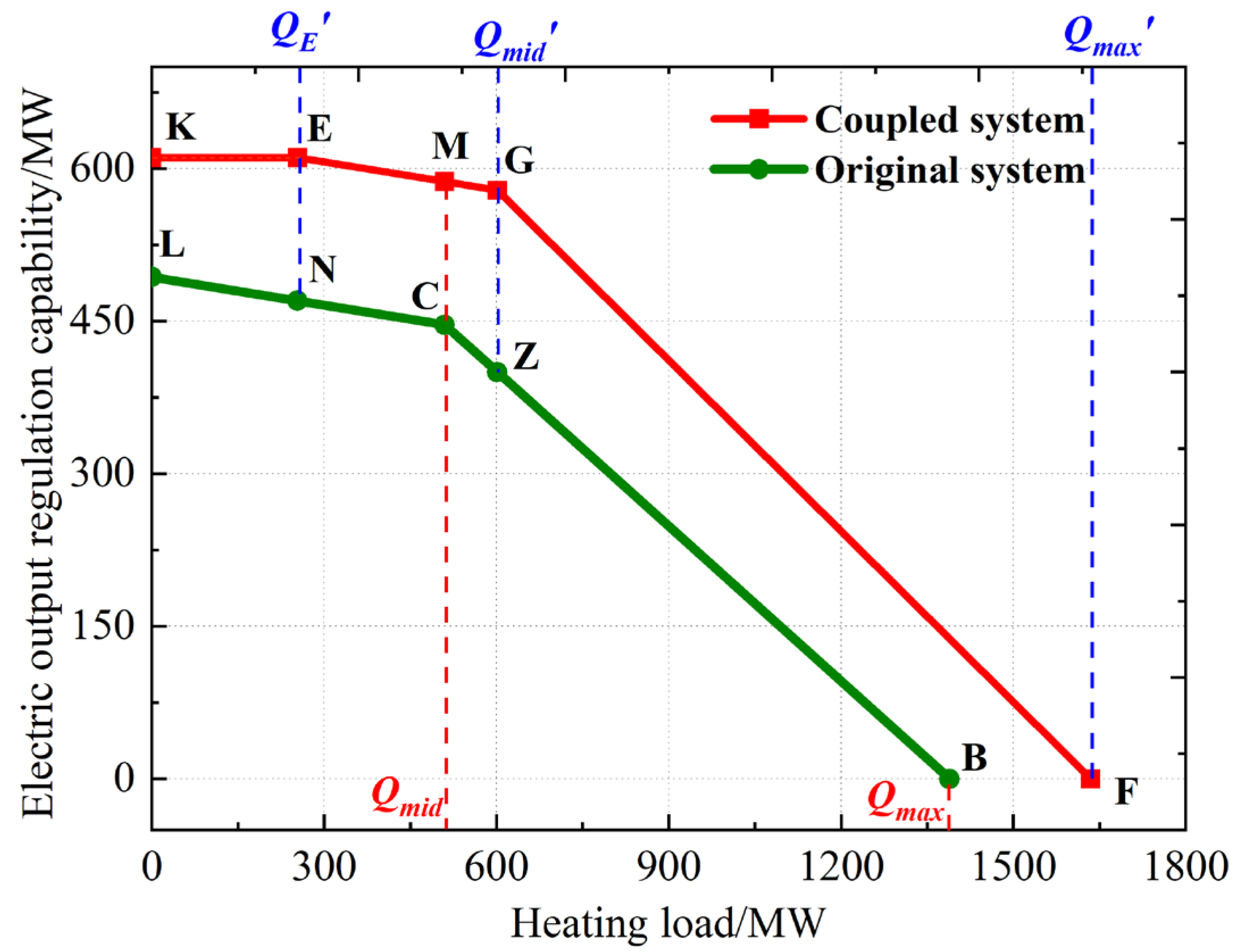
3.3. Electrical Output Regulation Capability of Systems

To calculate the electrical output regulation capability of systems, Figure 7 gives each operational point of the CCGT system. For the original system, the electrical output regulation capability (∆P) can be expressed as
0 Q Q m i d , P = ( P Q max P max Q max P min P Q min Q m i d ) Q + P max P Q min
Q m i d Q Q max , P = P Q max P max Q max Q ( P Q max P min Q max Q m i d ) ( Q Q max ) + P max P Q max
where Q is the heating load, Qmax is the maximum heating load, Pmax is the maximum generating power under pure condensing conditions, Pmin is the minimum generating power under heating conditions, PQmax is the generating power corresponding to the maximum heating capacity, PQmin is the generating power corresponding to the minimum heating capacity, and Qmid is the maximum heating load corresponding to the minimum generating power [32].
For the coupled system, the power output regulation capability (△P′) can be given as
0 Q Q E ,   P = P max P H
Q E Q Q m i d ,   P = P Q max P max Q max Q E ( Q Q E ) + P max P H
Q m i d Q Q max , P = P Q max P max Q max Q E ( Q Q E ) + P max P Q max P H Q max Q m i d ( Q Q max ) P Q max
where QE′ is the maximum heating load without the load reduction of the coupled system, Qmax′ is the maximum heating load of the coupled system, and Qmid′ is the maximum heating load corresponding to the minimum generating power of the coupled system.
As shown in Figure 8, the calculated change curves of the electrical output regulation capability of the original system and the coupled system are line-segments LNCZB and KFMGF, respectively. It can be seen that the molten salt energy storage device significantly improves the electrical output regulation capability of the system, but the degree of improvement is different at different stages.
Within the low heat supply load range (0 ≤ QQE), the electrical output regulation capability of the coupled system remains unchanged while that of the original system decreases, resulting in an increasing trend of increment. When the heating load reaches QE, the electrical output regulation capability of the original system and the coupled system is 470.15 MW and 610.97 MW, respectively. At this time, the increment is about 140.82 MW, and the electrical output regulation capability of the system is improved by 29.95%. In the process of continuously increasing the heat supply to QE, the increment continues to increase, indicating that the electrical output regulation capability of the system continues to improve. When the heating load reaches Qmid, the electrical output regulation capability of the original system and the coupled system is 400.03 MW and 578.71 MW, respectively, and the increment is 178.68 MW. At this time, the limit of the system’s ability to increase the electrical output regulation is reached by 44.66%, because the increment shows a decreasing trend as the heating load continues to increase. The main reason is that under high heating loads, the electrical output regulation capability of the system will be limited and it will not be able to further increase the electrical output.
In general, the investment in molten salt energy storage devices can improve the electrical output regulation capability under different heating loads, especially middle and low heating loads, but there is an upper limit to this improvement.

3.4. Thermal Performance Evaluation of Systems

This paper evaluates the thermal performance of the system using the thermoelectric ratio, gas consumption rate, and peaking capacity ratio. The thermoelectric ratio, X, refers to the ratio of the heating load to the electric load, which can be defined as
X = Q P e
where Q is the heating load and Pe is the electric load [33].
The calorimetric method is used to calculate the gas consumption rate of system, given as
b e = G g Q a r , n e t Q q a r , n e t P e
where be is the gas consumption rate, Gg is the natural gas mass flow rate, Qar,net is the natural gas net calorific value (Qar,net = 50.02 MJ/Nm3), and qar,net is the calorific value of natural gas (qar,net = 36.44MJ/m3).
The peak shaving capacity ratio (Rg) can be expressed as
R g = P e , max P e , min P e , N
where Pe,max and Pe,min denote the maximum and minimum generating power of the system at a certain heating load, respectively. Pe,N is the system rated power [34].
Table 5 compares the data changes in the heating load, electric load, and thermoelectric ratio of the system under different heat load conditions before and after coupling with molten salt energy storage.
On the one hand, the minimum electrical output after the system couples with molten salt energy storage is reduced by 72 MW, a decrease of 45.9%. The reason for this change is that the energy storage unit is able to collect waste heat from the gas turbine exhaust gas when the demand for electricity is low. This allows the steam turbine to reduce the generating power without affecting the operation of the gas turbine. This not only improves the efficiency of the gas turbine at low loads, but also reduces the minimum generation load of the entire system. On the other hand, the coupled system can rapidly increase the electrical power of the steam turbine by releasing the heat in the energy storage device during peak power consumption, thus increasing the maximum heating load. This enhances the peak regulation capacity of the system, allowing the system to respond more flexibly to changes in the grid load.
In addition, the gas consumption rate of the system also changes significantly. When the heating load is high, the peaking operation of the coupled system can reduce the loss of the cold source, as well as the rate of power generation fuel consumption, so as to improve the economy. However, when the heating load is low, because the gas turbine efficiency decreases with the load reduction, the peaking operation of the coupled system may lead to an increase in the gas turbine efficiency reduction, resulting in an increase in the electricity generation consumption rate and a decrease in economy.
From the graphical data presentation in Figure 9, the key performance indexes of the coupled system, namely the maximum heat-to-power ratio, minimum power steam consumption rate, maximum power steam consumption rate, and peak load capacity ratio, are better than those of the original system.
The maximum heat-to-power ratio of the original system is 3.25, while that of the coupled system is significantly improved to 7.07. This phenomenon shows that under the condition of a certain amount of heat supply, the coupled system can improve the thermoelectric conversion efficiency on the basis of reducing the generation output. This is particularly important for the uptake of wind power during heating, as it allows the system to make more efficient use of electricity generated from renewable sources while meeting heating needs. In addition, due to the energy loss during energy storage and energy release, the minimum and maximum power steam consumption rates of the coupled system are increased. This means that the system needs to consume more steam per unit of power generation, which is one of the unfavorable factors affecting the thermal economy. However, this increase in steam consumption is acceptable in terms of increased operational flexibility and peak regulation capacity, especially when considering the improved overall system performance. The peak load capacity ratio of the original system is 0.64, while that of the coupled system is 0.73, with an increase of 13.5%. This shows that the coupling of the molten salt energy storage device significantly increases the adjustable range of the power generation load and enhances the operational flexibility of the system. This kind of improvement is of great significance for coping with the fluctuation of power demand and the peak load balancing demand of the power grid, and helps to improve the stability and reliability of the power system.

4. Conclusions

This paper discusses a conventional combined gas turbine system coupling with a molten salt thermal energy storage device, as well as the system operation’s flexibility, peak regulation ability, and economy. The conclusions are as follows:
(1)
A method of coupling a molten salt thermal energy storage device with a combined cycle gas turbine system is proposed. When the energy demand is reduced, the molten salt thermal energy storage device will adjust the plan. On the contrary, we can use the heat stored in high-temperature molten salt to release energy, improving the flexibility of unit operation and the energy configuration ability of the power system.
(2)
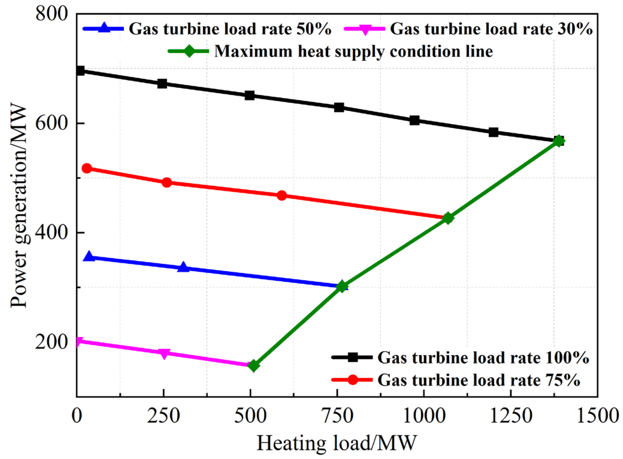
Before coupling the molten salt heat storage device in the extraction mode, the combined cycle gas turbine unit has the maximum and minimum generation power when the heat supply is constant. With the increase in heat supply, the difference between the total and minimum generation power becomes smaller and smaller, and the peaking capability of the combined cycle gas turbine unit becomes worse.
(3)
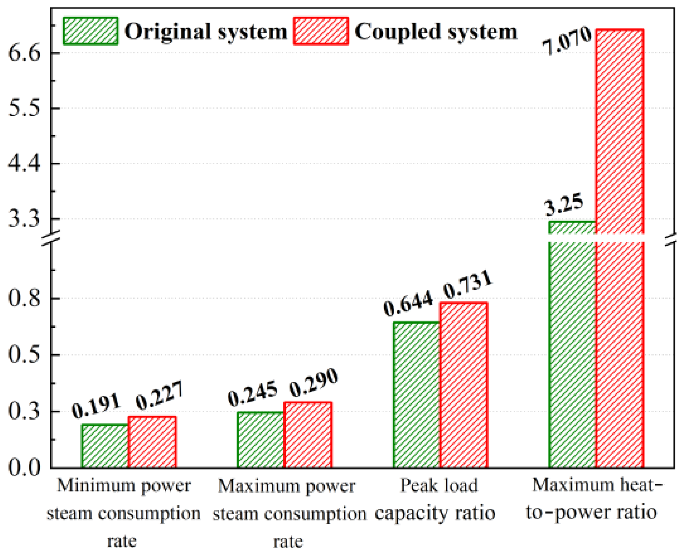
After coupling the molten salt heat storage device, the maximum generation power of the combined cycle gas turbine unit is increased while the minimum generation power decreases. The electrical output regulation capability is increased by 29.95–44.66%, and the heating capacity is increased by 17.69%. With the increase in heat supply, the difference between the maximum and minimum generation power increases, and the peaking capability of the coupled system increases. The peaking capacity ratio increases from 0.64 to 0.73, which is 13.5% higher than that of the original system.
(4)
When the heating load is high, the cold source loss of the coupling system and the gas consumption rate of power generation are reduced, resulting in the economy’s improvement. When the heating load is low, the efficiency loss of the gas turbine in the peak-shaving operation of the coupled system increases, the generation gas consumption rate of power generation increases, and the economy decreases. The maximum thermoelectric ratio of the coupled system can reach 7.07.
The coupling of the molten salt energy storage device improves the peak regulation capacity and operational flexibility of the CCGT system and optimizes the system’s economy to a certain extent. However, several areas remain open for further research. Future work should focus on enhancing the response speed of power demand changes, optimizing thermal management, and conducting comprehensive economic and environmental assessments. Additionally, the integration of this system with renewable energy sources should be explored to maximize its potential for sustainable energy development.

Author Contributions

Investigation and Writing—original draft: L.C.; Formal analysis and Methodology: J.Y.; Writing—review and editing: L.W.; Validation and Writing: X.X. All authors have read and agreed to the published version of the manuscript.

Funding

This research received no external funding.

Data Availability Statement

The data used to support the findings of this study are available from the corresponding author upon request.

Acknowledgments

We would like to thank all the participants for their participation in this study.

Conflicts of Interest

Author Xin Xu was employed by the Economic and Technological Research Institute of State Grid Jilin Electric Power Co., Ltd. Author Lei Wang was employed by the State Grid Jilin Electric Power Research Institute. The remaining authors declare that the research was conducted in the absence of any commercial or financial relationships that could be construed as a potential conflict of interest.

Nomenclature

Abbreviations
CCGTcombined cycle gas turbine
MELminimum environmental load
HPSThigh-pressure steam turbine
IPSTintermediate-pressure steam turbine
LPSTlow-pressure steam turbine
NGCCnatural gas combined cycle
CAEScompressed air energy storage
ORCorganic Rankine cycle
SNGCCsupercharged natural gas combined cycle
HRSGheat recovery steam generator
IGVinlet guide vane
EGRexhaust gas recycle
IGVCinlet guide vane control
EGRRexhaust gas recirculation rate
CSPconcentrated solar power
MSEMmultistage steam expansion system
CLHScascaded latent heat storage
ACAESadiabatic compressed air energy storage
GTgas turbine
HPThigh-pressure turbine
HPhigh pressure
IPintermediate pressure
IPTintermediate-pressure turbine
LPlow pressure
LPTlow-pressure turbine
THAturbine heat acceptance
Symbols
Qact,maxactual maximum energy supply, MW
Qthe,maxtheoretical maximum energy storage, MW
ηefficiency of energy storage, %
△Pelectrical output regulation capability of original system, MW
△P’electrical output regulation capability of coupled system, MW
Qheating load, MW
Qmaxmaximum generating heating load of original system, MW
PQmaxgenerating power corresponding to the maximum heating capacity of original system, MW
PQmingenerating power corresponding to the minimum heating capacity of original system, MW
Pmaxmaximum generating power of original system, MW
Pminminimum generating power of original system, MW
Qmidmaximum heating load corresponding to the minimum generating power of original system, MW
Q’Emaximum heating load without load reduction in coupled system, MW
Q’maxmaximum heating load of coupled system
Q’midmaximum heating load corresponding to the minimum generating power of coupled system, MW
Xthermoelectric ratio
Qheating load, MW
Peelectric load, MW
begas consumption rate, m3/kW·h
Ggnatural gas mass flow rate, kg/s
Qar,netnatural gas net calorific value, MJ/Nm3
qar,netcalorific value of natural gas, MJ/Nm3
Rgpeak shaving capacity ratio, %
Pe,maxmaximum generating power at a certain heating load, MW
Pe,minminimum generating power at a certain heating load, MW
Pe,Nsystem rated power, MW

References

  1. Ahmad, J.; Adeel, J.; Abdul, W.; Muhammad, O.Z.; Majid, A.; Asif, H.K.; Muhammad, I. Multiparametric optimization for reduced condenser cooling water consumption in a degraded combined cycle gas turbine power plant from a water-energy nexus perspective. Appl. Energy 2021, 304, 117764. [Google Scholar] [CrossRef]
  2. Zhi, W.; Qirun, S.; Yuping, L.; Wei, G.; Pengxiang, L.; Renjie, D.; Siming, W. Distributed chance-constrained based total energy supply capability evaluation method for integrated power and natural gas system. Int. J. Electr. Power Energy Syst. 2022, 141, 108193. [Google Scholar] [CrossRef]
  3. Mahmut, D. Prediction of NOx emissions from gas turbines of a combined cycle power plant using an ANFIS model optimized by GA. Fuel 2022, 321, 124037. [Google Scholar] [CrossRef]
  4. Na, W.; Hongbo, T.; Xiaoqiao, Q. Simulation and analysis of a peak regulation gas power plant with advanced energy storage and cryogenic CO2 capture. Energy Storage Sav. 2023, 2, 479–486. [Google Scholar] [CrossRef]
  5. Andrew, L.; Braden, C.; LaGrande, G.; Austin, B.; Logan, B.; Nick, R.; Matthew, M. Thermal design and analysis of a passive modular molten salt microreactor concept. Nucl. Eng. Des. 2023, 402, 112107. [Google Scholar] [CrossRef]
  6. Andreas, U.; Göran, A. Analyzing operational flexibility of electric power systems. Int. J. Electr. Power Energy Syst. 2015, 72, 155–164. [Google Scholar] [CrossRef]
  7. Chengxu, C.; Yichen, Z.; Zhihua, G.; Xiaoze, D.; ELSaeed, S.E. Comparative study on flexibility enhancement of combined heat and power for wind power accommodation. Appl. Therm. Eng. Des. Process. Equip. Econ. 2023, 235, 121287. [Google Scholar] [CrossRef]
  8. Kamal, A.; Uyioghosa, I.; Ioannis, R.; Richard, H. Impact of gas turbine flexibility improvements on combined cycle gas turbine performance. Appl. Therm. Eng. 2021, 189, 116703. [Google Scholar] [CrossRef]
  9. Polyzakis, A.L.; Koroneos, C.; Xydis, G. Optimum gas turbine cycle for combined cycle power plan. Energy Convers. Manag. 2008, 149, 551–563. [Google Scholar] [CrossRef]
  10. Zuming, L.; Karimi, I.A. Simulation of a combined cycle gas turbine power plant in Aspen HYSYS. Energy Procedia 2019, 158, 3620–3625. [Google Scholar] [CrossRef]
  11. Sylwia, K.G.; Paweł, Z.; Iliya, I.; Gabriel, P.N.; Janusz, B. Techno-economic evaluation of combined cycle gas turbine and a diabatic compressed air energy storage integration concept. Energy 2023, 266, 126345. [Google Scholar] [CrossRef]
  12. Yang, C.; Huanxin, L.; Ping, W.; Kunle, F.; Zhifeng, H.; Xiaoqian, M. Economic analysis on peak-regulation of GTCC cogeneration unit with extraction heating. Proc. CSEE 2020, 40, 592–600. [Google Scholar] [CrossRef]
  13. Bălănescu, D.T.; Homutescu, V.M. Performance analysis of a gas turbine combined cycle power plant with waste heat recovery in Organic Rankine Cycle. Procedia Manuf. 2019, 32, 520–528. [Google Scholar] [CrossRef]
  14. Linda, B.; Andrea, O. Supercharged gas turbine combined cycle: An improvement in plant flexibility and efficiency. Energy 2015, 81, 615–626. [Google Scholar] [CrossRef]
  15. Vahab, H.H.; Afef, F.; Concepción, A.M.; Ramin, F.A. H2, H, H2/H, and μ-synthesis controllers for the speed and temperature control of a real gas turbine unit in a combined cycle power plant. Energy Sci. Eng. 2019, 7, 2205–2222. [Google Scholar] [CrossRef]
  16. Zuming, L.; Iftekhar, A.K. New operating strategy for a combined cycle gas turbine power plant. Energy Convers. Manag. 2018, 171, 1675–1684. [Google Scholar] [CrossRef]
  17. Yufei, Z.; Hanfei, Z.; Shuo, L.; Ziyi, L.; Xingqi, D.; Liqiang, D.; Umberto, D. Experimental study on heat transfer characteristics between high-pressure air and molten salt used in solar-aided compressed air energy storage systems. Energy 2024, 313, 134127. [Google Scholar] [CrossRef]
  18. Xue, X.; Yifan, Z.; Xiang, L.; Ao, Z.; Hao, Z. 1.05 MW molten salt furnace experimental investigation of full-conditional thermal energy storage for the transfer and storage of waste heat from blast furnace gas. Renew. Energy 2024, 231, 120955. [Google Scholar] [CrossRef]
  19. Burcu, K.; Marc, M.; Camila, B.; Ana, I.F.; Halime, P. Performance analysis of a molten salt packed-bed thermal energy storage system using three different waste materials. Sol. Energy Mater. Sol. Cells 2024, 278, 113199. [Google Scholar] [CrossRef]
  20. Shuai, Z.; Ziyuan, L.; Yuanpeng, Y.; Limei, T.; Yuying, Y. Heat transfer characteristics and compatibility of molten salt/ceramic porous composite phase change material. Appl. Therm. Eng. 2022, 100, 107476. [Google Scholar]
  21. Appasaheb, R.; Sandip, K.S.; Mohit, J. Transient performance analysis of concentrating solar thermal power plant with finned latent heat thermal energy storage. Renew. Energy 2020, 145, 1957–1971. [Google Scholar] [CrossRef]
  22. Qijun, Z.; Jianning, D.; Heng, C.; Fuyuan, F.; Gang, X.; Xiuyan, W.; Tong, L. Dynamic characteristics and economic analysis of a coal-fired power plant integrated with molten salt thermal energy storage for improving peaking capacity. Energy 2024, 290, 130132. [Google Scholar] [CrossRef]
  23. Soto, G.J.; Wagner, M.J.; Neises, T.W.; Lindley, B.A. Performance analysis of integrated Nuclear-Solar Energy system sharing same molten salt thermal energy storage. Prog. Nucl. Energy 2024, 171, 105166. [Google Scholar] [CrossRef]
  24. Ehsanolah, A.; Mehdi, P.; Siamak, H.; Moonyong, L. A new analysis for a concentrated solar power-based cogeneration system with molten salt energy storage and heat recovery steam generator-Case study(USA, France, Canada). Renew. Energy Focus 2023, 46, 256–280. [Google Scholar] [CrossRef]
  25. Decai, L.; Yukun, H.; Dacheng, L.; Jihong, W. Combined-cycle gas turbine power plant integration with cascaded latent heat thermal storage for fast dynamic responses. Energy Convers. Manag. 2019, 183, 1–13. [Google Scholar] [CrossRef]
  26. Jacek, D.W.; Jihong, W. Feasibility study of Combined Cycle Gas Turbine (CCGT) power plant integration with Adiabatic Compressed Air Energy Storage (ACAES). Appl. Energy 2018, 221, 477–489. [Google Scholar] [CrossRef]
  27. ISO 18888:2017; Gas Turbine Combined Cycle Power Plants—Thermal Performance Tests. ISO: Geneva, Switzerland, 2017.
  28. EBSILON Professional 16.0 (Simulation Software). STEAG Energy Services-System Technologies. 2024. Available online: https://www.ebsilon.com/en/ (accessed on 18 February 2025).
  29. Muhammad, F.; Ahmed, K.A.; Binjian, N.; Imran, A. Thermal energy storage integration with nuclear power: A critical review. J. Energy Storage 2024, 96, 112577. [Google Scholar] [CrossRef]
  30. Nianci, L.; Lei, P.; Simon, P.; Deli, Z.; Ahmad, A. A complete dynamic modeling of two-by-one gas-steam combined cycle unit for coordinated control design. Appl. Therm. Eng. 2024, 253, 123766. [Google Scholar] [CrossRef]
  31. Adams, T.; Dowell, N.M. Off-design point modelling of a 420 MW CCGT power plant integrated with an amine-based post-combustion CO2 capture and compression process. Appl. Energy 2016, 178, 681–702. [Google Scholar] [CrossRef]
  32. Xin, H.; Chengchen, L.; Huanran, W. Thermodynamics analysis of a combined cooling, heating and power system integrating compressed air energy storage and gas-steam combined cycle. Energy 2022, 260, 125105. [Google Scholar] [CrossRef]
  33. Tengfei, Z.; Sayed, F.A.; Manoj, K.A.; Ahmad, Y.A.B.A.; Ayman, A.G.; Prajoona, V.; Nehad, A.S.; Xiaomin, G. Design and thermo-enviro-economic analyses of a novel thermal design process for a CCHP-desalination application using LNG regasification integrated with a gas turbine power plant. Energy 2024, 295, 131003. [Google Scholar] [CrossRef]
  34. Serhat, K.; Mustafa, I. Experimental and numerical analysis of turbulent premixed combustion of low calorific value coal gases in a generated premixed burner. Fuel 2018, 220, 586–598. [Google Scholar] [CrossRef]
Figure 1. Principle system diagram for combined cycle gas turbine units.
Processes 13 00604 g001
Figure 2. Schematic diagram of the coupling system.
Processes 13 00604 g002
Figure 3. Steam turbine component; 1: steam inlet; 2: steam outlet; 3: drive shaft inlet; 4: drive shaft outlet.
Processes 13 00604 g003
Figure 4. Steam turbine component; 5: cooling water inlet; 6: cooling water outlet; 7: turbine extraction inlet; 8: turbine extraction outlet; 9: drain inlet.
Processes 13 00604 g004
Figure 5. Electrical and thermal characteristic curve of combined cycle gas turbine heating unit.
Processes 13 00604 g005
Figure 6. Comparison of simulated and designed values for typical operating conditions.
Processes 13 00604 g006
Figure 7. Electrical and thermal characteristics curves of coupled units.
Processes 13 00604 g007
Figure 8. Combined cycle gas turbine unit electrical output regulation capability.
Processes 13 00604 g008
Figure 9. System thermal performance comparison.
Processes 13 00604 g009
Table 1. Main equipment parameters and design condition parameters.
Gas Turbine
TypeM701F4, heavy-duty, axial-flowStage of gas turbine4
Rated speed (rpm)3000Efficiency (%)39.9
Exhaust temperature (°C)576Single power (MW)346.32
Single displacement (t/h)2808.60Exhaust pressure (kPa)3.93
Gas turbo-compressorBlade number17
Typeaxial-flow
Pressure ratio18 (ISO 18888:2017) [27]
Adjustable blade1
Gas turbine combustorTypedry, low NOx
Burner number20
Steam turbine
ModelTC2F-40.5inchTypethree-pressure reheat/double-cylinder operation
Length of last stage blade (mm)1029Power (MW)143.6
Steam pressure (MPa)Main steam of high-pressure cylinder12.59
Reheat steam3.36
Steam temperature (°C)Main steam of high-pressure cylinder523.90
Reheat steam549.20
Steam flow rate (t/h)Main steam of high-pressure cylinder584.10
Reheat steam730.90
HRSG
TypeNon-supplementary combustion, horizontal, three-pressure reheat, natural circulation boilerMaximum pressure drop of gas side (kPa)3.93
High-pressure sectionMass flow rate of steam (t/h)292.10
Outlet steam pressure (MPa)12.97
Outlet steam temperature (°C)525.90
Reheat sectionMass flow rate of steam (t/h)365.40
Outlet steam pressure (MPa)3.45
Outlet steam temperature (°C)551.20
Intermediate-pressure sectionMass flow rate of steam (t/h)82.30
Outlet steam pressure (MPa)3.66
Outlet steam temperature (°C)292.90
Low-pressure sectionMass flow rate of steam (t/h)44.20
Outlet steam pressure (MPa)0.70
Outlet steam temperature (°C)246.60
Table 2. Performance and major techno-economic indexes of combined cycle gas turbine units.
NameValueNameValue
Heating load (MW)695.40Power (MW)836.24
Single fuel quality (t/h)67.49Extraction flow for heat supply (t/h)834.60
Fuel gas density (kg/m3)0.72Efficiency of HRSG (%)82.60
Table 3. Physical and thermal characteristics of PCM.
NameValueNameValue
TypeKCl(54)-46ZnCl2Heat storage efficiency (%)78
Ρ (kg/m3)2410Capacity of heat storage tank (m3)700–20,000
c p s , PCM (J/kg·K)670Energy storage time (h)1.28
c p l , PCM (J/kg·K)880λPCM (W/m·K)0.83
Tm (K)705L (kJ/kg)218
Table 4. Entropy change for the major components.
Gas TurbineSteam TurbineHRSG
Entropy change (kJ/kg)1.361.281.55
Table 5. Thermal performance of units before and after coupling with molten salt thermal storage.
ProjectBeforeAfter
Corridor 0 Q mid Q mid Q max 0 Q mid Q mid Q max
Thermal Load (MW)0–509.66509.66–1388.940–601.22601.22–1634.64
Electrical Load (MW)157.03–696.00157.03–649.4285.03–696.0085.03–589.98
Thermoelectric Ratio0–3.250.78–2.450–7.071.02–2.77
Generation Gas Consumption Rate/m3 (kW·h)0.19–0.240.22–0.250.23–0.290.23–0.27
Peaking Capacity Ratio/%0.640.73
Disclaimer/Publisher’s Note: The statements, opinions and data contained in all publications are solely those of the individual author(s) and contributor(s) and not of MDPI and/or the editor(s). MDPI and/or the editor(s) disclaim responsibility for any injury to people or property resulting from any ideas, methods, instructions or products referred to in the content.

