Abstract
In this paper, we briefly discuss the main points of salinity gradient energy (SGE). First, we discuss the sources of SGE and the methods to harvest it. Then, we calculate, using the laws of physical chemistry, the amount of energy that can be harvested with three selected methods based on the diffusion of ions, liquid water, and water vapor, respectively. Then, we give an overview of the applications, highlighting a number of new developments such as assisted reverse electrodialysis (ARED) and energy storage. It turns out that reverse electrodialysis offers unexpected possibilities such as energy storage, utilizing waste heat, and the administration of transdermal drug delivery, a technique that has been launched very recently.
1. Introduction
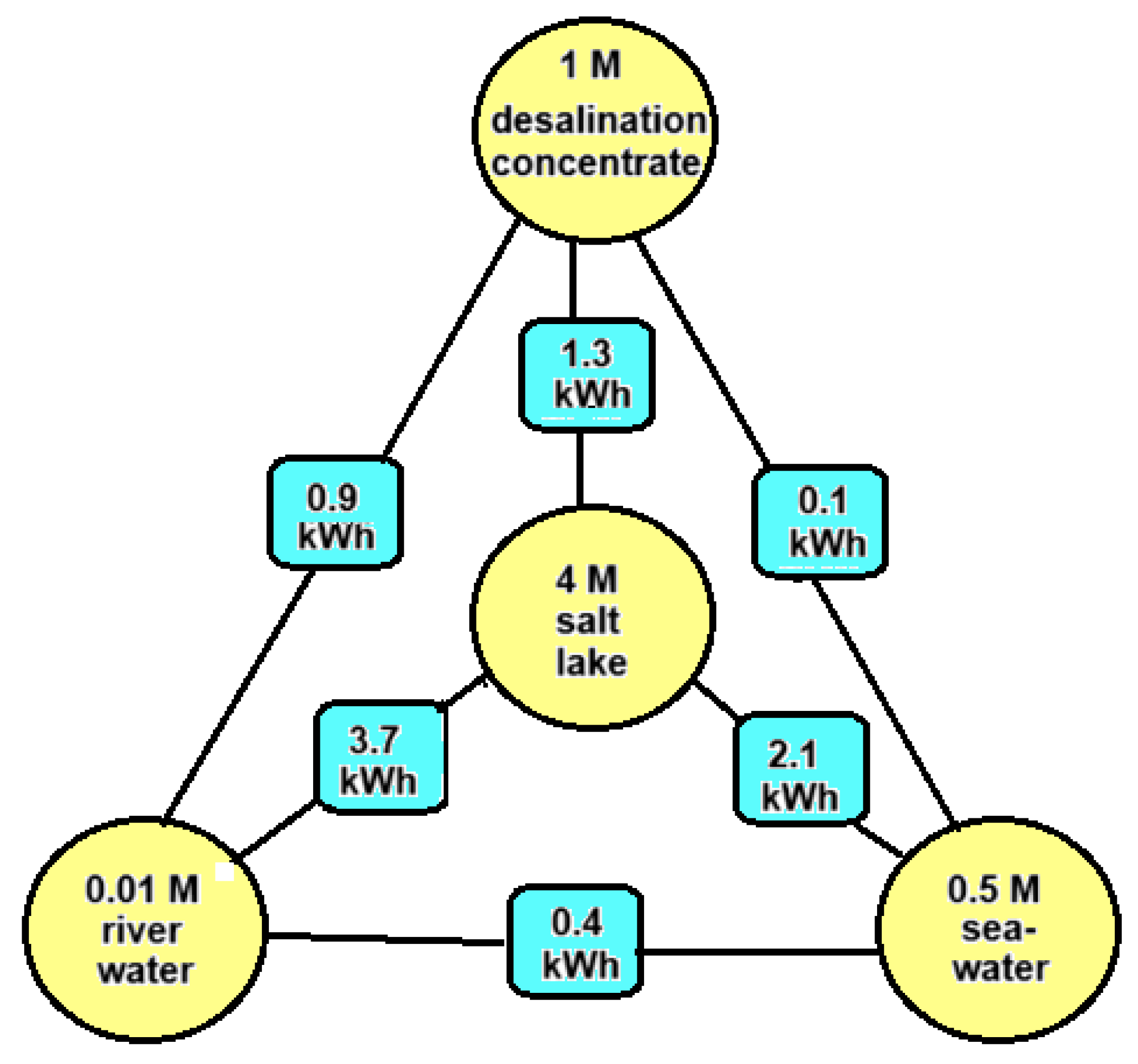
It is possible to harvest so-called salinity gradient energy (SGE) from two salt solutions with different salt concentrations by means of reversible mixing. The amount of this Gibbs energy is small compared to energy contained in fossil fuels. For example, the theoretical potential of 1 m3 of river water with an equal amount of seawater is approximately 1.5 MJ (0.5 kWh), while the same volume of gasoline represents 32.2 GJ (895 kWh) or approximately 20,000 times as much. It is clear that SGE can only be economically attractive if both feed waters are available close to each other and if pre-treatment and pumping are carried out very efficiently. Worldwide, there is—if all river water is used—a potential of 2.7 TW [1], which is comparable to the average global electricity consumption of 3 TW [2], and this huge amount is an incentive to develop methods to exploit this energy source. The main possible sources for SGE are river water, sea water, concentrate from reverse osmosis desalination units, and brine from salt lakes. Figure 1 shows how much SGE can be harvested theoretically by the reversible mixing of 1 m3 plus 1 m3 of these feed waters.
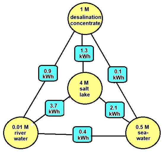
Figure 1.
Energy potential in kWh by reversible mixing different combinations of feed waters (each 1 m3). Energies are calculated with the theoretical model as presented in Section 3 of this paper.
Based on Figure 1, we arrive at the following feed water combinations:
- River water + seawater: These feed waters are most abundant. SGE generated with this combination is known as blue energy. The Dutch company REDstack is developing SGE using the reverse electrodialysis (RED) technology for economic deployment [3].
- Seawater + desalination concentrate: Most reverse osmosis (RO) systems operate with a recovery rate of about 50%, which results in a concentrate having twice the salinity of seawater, about 1 M [4]. The energy content of this combination is four times smaller than combination A and is therefore not very attractive. However, in contrast to RO systems, the recovery of thermal desalination plants is much higher, and the concentrate may be in the order of 3 M. Moreover, this concentrate is relatively hot and in this case, the generation of SGE with seawater is a good option [5].
- River water + desalination concentrate: Desalination plants are placed in dry areas where there are usually no rivers. However, municipal wastewater from the neighboring city, which also has a low salt content, may be available to generate SGE in combination with desalination concentrate [6].
- River water + salt lake: If the water from a salt lake together with the inflow river is used, no net change in the salinity conditions in the lake occur. If the lake has no outflow—known as an endorheic basin—the salinity can be very high. An example is the Great Salt Lake in the USA [7].
- Seawater + salt lake: The Dead Sea is drying up, and the reason is that more and more water is being extracted from the inflowing Jordan river. Ideas have been put forward to raise the water level again by supplying water from the Mediterranean Sea or from the Red Sea. Because the Dead Sea is 400 m below sea level, energy can in principle also be generated with a hydroelectric power station. In addition, there is the possibility of using the difference in salinity for SGE. The latter was first proposed by Sydney Loeb and was later further elaborated by others [8].
- Salt lake + desalination concentrate: The combination of these feed waters is not very realistic, but there are new industrial sources of high concentrated brines. These include the water that is released during oil drilling (“produced water”) as well as the residual brine that remains after lithium extraction. If there is also water with a lower concentration in the vicinity, this creates the possibility of generating SGE. Due to the large variety in concentrations of these solutions, these applications do not fit well into the above scheme. We mention the work of Huang et al. [9], who started from produced water (93 g/L) as well as water from a nonpotable aquifer (13 g/L). With PRO, the authors were able to generate a power of 1.4 W/m2 membrane with PRO.
Research has also been conducted into RED’s use of produced water for energy harvesting. Abbas and Al-Furaiji tested the combination of artificial oil field co-produced water (250 g NaCl/L) together with artificial seawater (30 g NaCl/L) [10]. The power density was 0.03 W/m2. Cosenza et al. performed experiments with real produced waters combined with a pure NaCl solution of 0.7 g/L NaCl [11]. This yielded a power density of 2.5 W/m2.
2. Methods of SGE, a Brief History, and the Ideas That Follow from It
There are three basic methods to generate SGE, namely the diffusion of ions, liquid water, and water vapor.
2.1. Diffusion of Ions
When using the diffusion of ions, in most cases, ion exchange membranes (IEMs) are applied. There are two types—anion exchange membranes (AEMs) mainly allow anions to pass through and cation exchange membranes (CEMs) mainly allow cations. In addition, there is also a technique that does not require a membrane, the so-called external charged capacitive mixing.
2.1.1. Reverse Electrodialysis (RED)
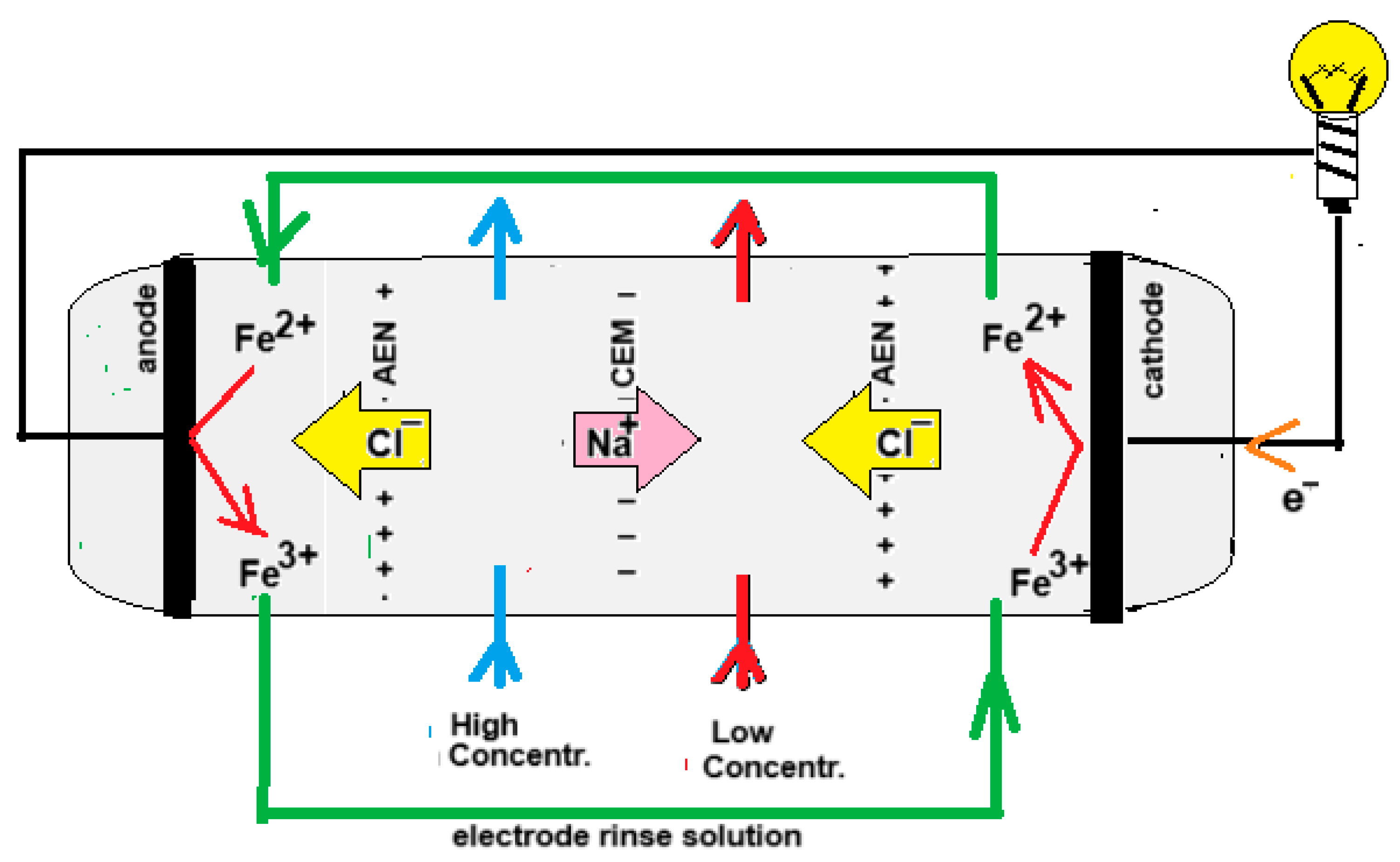
In 1942, Manecke published an article called Membranakkumulator [12]. At that time, electrodialysis (ED) was already a well-known technique, but Manecke came up with the idea of using ED in a battery. By passing an electric current through a KCl solution, a solution with low concentration (LC) and one with high concentration (HC) were created. After loading the battery in this way, he reversed the ED process and then electricity was generated, a technique that is now known as reverse electrodialysis (RED). In 1954, Pattle picked up this idea again and improved the RED stack. His vision was a novelty, it being that RED can be an energy source if seawater together with river water are used. The principle of RED is shown in Figure 2.
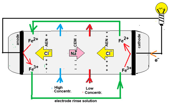
Figure 2.
Principle of an RED. For clarity, the drawn stack has only one cell pair, i.e., the combination of a CEM and an AEM. Commercial stacks are equipped with hundreds or thousands of cell pairs. The electrode rinse solution in this example contains Fe2+ and Fe3+ ions as a redox couple and a NaCl bulk for electrical conductivity. Because the terminating membranes are of the AEM type, the iron ions cannot leave the electrode compartments.
RED can be performed with four different electrode systems. These include systems with (i) participating electrodes, (ii) inert electrodes with the evolvement of gasses (H2 and Cl2 or O2), (iii) inert electrodes with a redox couple, and (iv) capacitive electrodes [13]. In addition, there are some applications that do not require electrodes.
- (i).
- Participating electrodes undergo chemical reactions. In 1976, Clampitt and Kiviat suggested harvesting SGE with a so called “concentration cell”, a device with two compartments separated by a anion exchange membrane (AEM) and equipped with Ag/AgCl electrodes. The generated EMF is due to the difference in the electrode potentials and the membrane potential; both generate about the same voltage. This principle is still widely used today in the field of nanofluidic membranes where most newly developed membranes are of the CEM type with very promising specifications. However, because there is no AEM counterpart, testing for usability in RED involves very simple systems: a cell with two Ag/AgCl electrodes with only one CEM in between.
A new development involves the battery electrodes that are mainly used in battery electrode deionization (BDI), a desalination technique that is closely related to capacitive ionization (CDI) [14]. The difference is that BDI uses battery electrodes and CDI uses activated carbon (AC). Battery electrodes (often based on the multivalence of transition metals) can specifically accept or release one specific type of ion in contrast to AC, which can exchange both anions and cations. Battery electrodes have been described for use in various forms of energy storage but not yet for RED [15,16].
- (ii).
- If the system uses only NaCl solutions in the electrode compartments, gasses are formed such as H2 and Cl2 or O2. For these chemical reactions, a part of the generated energy is used. Moreover, H2 is explosive and Cl2 toxic whereas at the cathode, OH¯ ions are formed and can be the cause of scaling on the electrode if calcium or magnesium ions are present.
- (iii).
- Systems with inert electrodes use an electrode rinse solution (ERS) with a redox couple and a bulk salt for good electrical conductivity. Most used are the iron ion couple (Fe2+/Fe3+) and the hexacyanoferrate couple ([Fe(CN)6]3−/[Fe(CN)6]4−). There are no net chemical reactions, and the power losses are relatively small.
- (iv).
- The fourth possibility is using capacitive electrodes. Vermaas et al. used activated carbon (AC) for this purpose [17]. In one electrode, anions are adsorbed and in the other cations. When the electrodes are saturated, the process can be inverted by switching the feed water inflows. Wu et al. used the CRED technique with a single membrane to study the membrane performance [18]. Feed water switches always introduce dead times during the feed water changes. A theoretical opportunity (but almost impossible in practice) is changing the solid carbon electrodes periodically. A more practical implementation of this idea is to pump a slurry of AC around the inert electrodes, a method investigated by Simões et al. [19].
- (v).
- Murphy used an RED system to drive an ED system for desalination and called it osmotic demineralization [20]. Both systems are directly coupled, and electrodes are not needed. A similar concept with only four compartments was studied by Veerman [21]. Another application of electrodeless RED is powering transdermal drug delivery. Patches loaded with the drug are attached to the skin, and the drug is transported through the skin by the generated voltage [22].
2.1.2. Capacitive Mixing (CapMix)
In 2009, Brogioli published a paper about an SGE generator consisting of a flow cell with only two capacitive electrodes [23]. The cell is connected to an electrical circuit that can both supply and extract energy. The water inflow is switched regularly; during the passage of seawater, the ions are directed to the electrodes by an applied voltage. If these are saturated, the inflow is switched from seawater to river water, which causes a reversal of the process and a higher voltage is now generated than during the previous phase. This externally charged capacitive mixing (also known as capacitive energy extraction based on double layer expansion, CDLE) triggered other researchers to improve this concept. In 2010, Sales connected an AEM to one electrode and a CEM to the other [24]. An external energy source was no longer needed and autogenerative capacitive mixing (also known as capacitive energy extraction based on Donnan potentials, CDP) was born. Later developments were the replacement of the capacitive electrodes by battery electrodes. These provide a larger capacity and therefore a feedwater switch was needed less frequently, which is advantageous because during this switch, the system is out of operation.
2.1.3. Microbial Reverse Electrodialysis
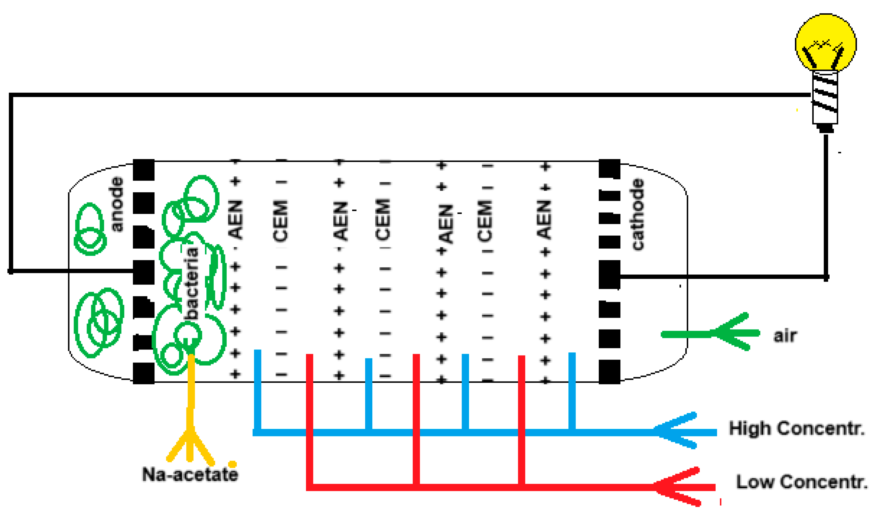
“Blue energy meets green energy in microbial reverse electrodialysis cells” is the beginning of the title of a recent review by Pandit et al. [25]. The combination of both techniques in a single device was launched by Younggy Kim and Bruce Logan in 2011 and is known as the “microbial reverse electrodialysis cell” (MRC) [26]. Figure 3 shows the principle of an MRC. The electrode compartments of a classic RED stack are modified as follows: air is injected into the cathode compartment while the anode is loaded with exoelectrogenic bacteria. The RED part is fed with salt and fresh water while the anode space is rinsed with an acetate solution that is a model for urban wastewater.
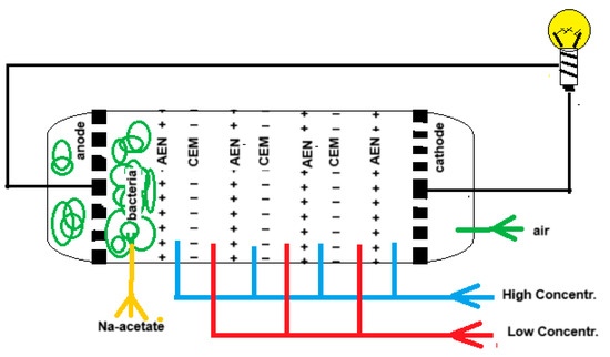
Figure 3.
A microbial reverse electrodialysis cell (MRC) with 3 cell pairs.
At the cathode, oxygen is reduced as follows:
H2O + ½ O2 + 2e → 2 OH−
At the anode acetate (or other organic material) is oxidized by exoelectrogenic bacteria.
Partial oxidation [27]:
2 H3C-COO− → H3C-CH3 + 2 CO2 + 2e
Total oxidation:
H3C-COO− + 2 H2O → 2 CO2 + 7 H+ + 8e
The MBC can purify wastewater and supply energy. In addition, the problem of charge transfer from the ions to the electrodes is solved.
The success of the MRC has led to a number of new applications. We will mention a few. Cusick et al. showed that the MRC also works well with ammonium bicarbonate instead of NaCl [28]. This salt is volatile, which means that the feed waters can be regenerated with heat. Due to a closed feed water system, the MRC is independent of fresh and salt water but derives its energy from waste heat.
Zhu et al. modified the MRC on two points [29]. They omitted the air supply to the cathode that results in hydrogen generation. Furthermore, a bipolar membrane was incorporated into the cell, which dissociated water into acid and alkali. Sequestration of the CO2 with serpentine minerals was performed outside the cell with the help of the obtained acid and alkali.
Luo et al. added a biocathode to the MRC, which produced methane [30].
D’Angelo et al. showed that Cr(VI) ions are reduced to less toxic Cr(III) by an MRC-based Fenton process [31], and Li et al. succeeded in the abatement of azo dye-polluted wastewater in an MRC [32].
Using seawater in an RED part of an MRC leads to reduced yield due to divalent cations. This problem was solved by Jwa et al. by treating the seawater in an external microbial electrolysis cell [MEC], where these ions were precipitated as Mg(OH)2 and CaCO3 [33].
2.2. Diffusion of Liquid Water
The most used technique based on the diffusion of liquid water is pressure-retarded osmosis, where water diffuses through a membrane. Other methods are based on the swelling of hydrophilic material in water.
2.2.1. Pressure-Retarded Osmosis (PRO)
In 1748, Jean Antoine (Abbé) Nollet discovered the phenomenon of osmosis [34]. Initially, osmosis was made visible using prepared pig bladders. If these are used as a semi-permeable membrane between two vessels containing solutions with different salinities, water will selectively diffuse into the vessel with the higher salt concentration (the real reason is of course that the water diffuses from the compartment with a high water concentration to the compartment with the low water concentration). If this latter vessel is sealed, a high pressure can be built up, namely 27 bar if one vessel contains seawater and the other fresh water.
This process can be reversed to desalinate seawater, but this places high demands on the membranes. It was not until 1964 that Sidney Loeb and Srinivasa Sourirajan were able to make reverse osmosis (RO) membranes consisting of a porous support layer with a thin skin layer on top [35]. The development of RO has been rapid and today, it is the main desalination technology for the production of drinking water from seawater.
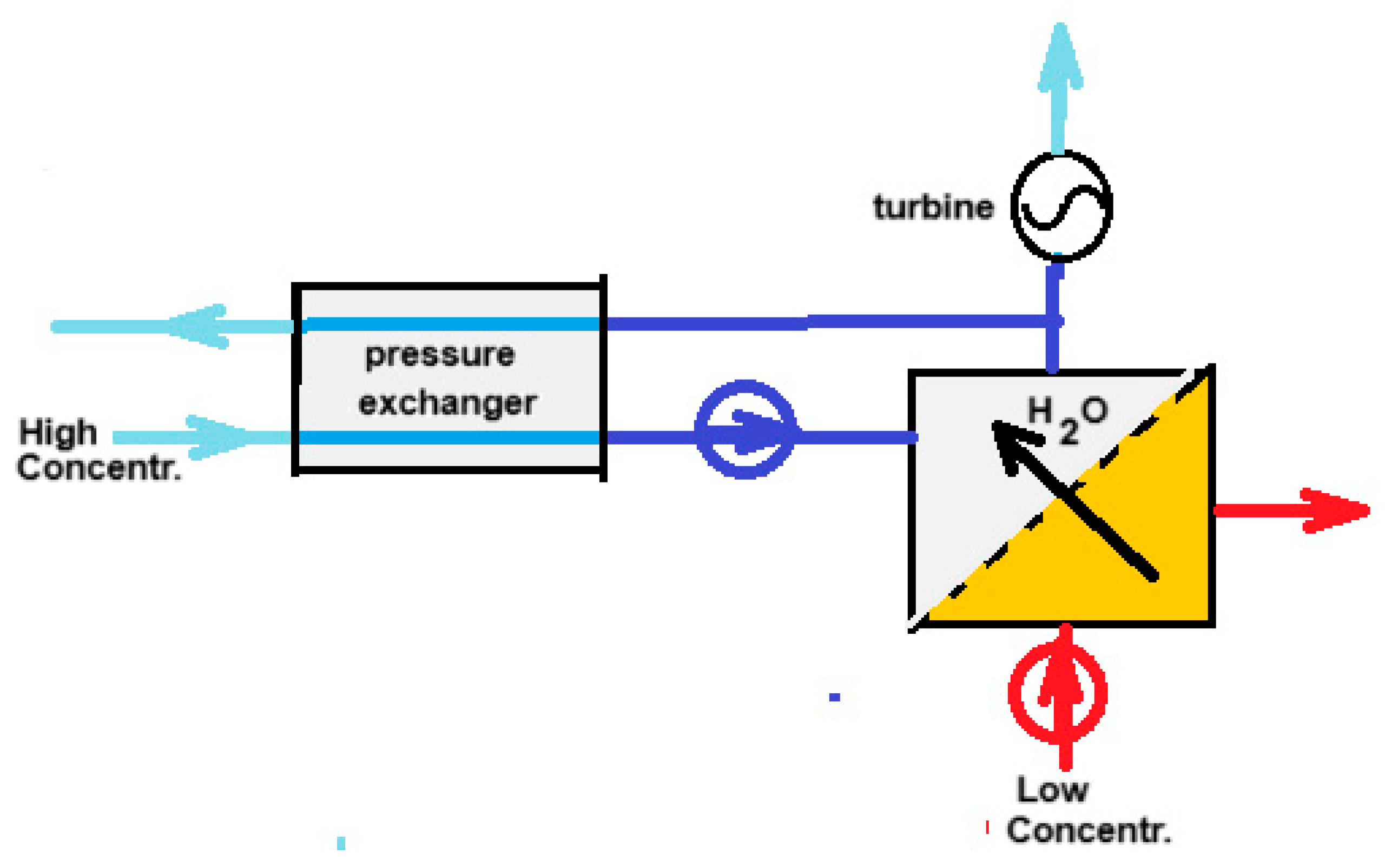
Almost ten years after the RO patent, Loeb came up with another patent—this time, a method to reverse the RO process [36]. In this way, energy can be generated by the reversible mixing of fresh and salt water. Loeb called the technique “Pressure retarded osmosis” (PRO). Almost simultaneous with Loeb’s patent, Norman published a hypothetical machine for generating energy by osmosis [37]. From this time on, PRO took flight in a way that was more or less parallel to the developments of RED. Nowadays, PRO, together with RED, are the most studied methods for SGE production. On Google Scholar “reverse electrodialysis” yields 8970 hits and “pressure retarded osmosis” 8860 hits (October 2024). The principle of PRO is shown in Figure 4. The input of salt water to the high-pressure system requires little energy because in the pressure exchanger, each liter of input is energetically compensated by each liter of output. Actually, a better name for this apparatus would be “volume exchanger”.
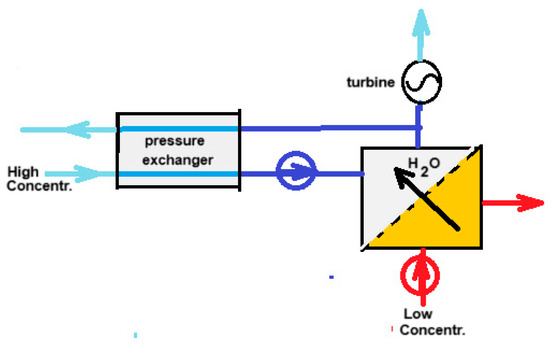
Figure 4.
Principle of PRO. High-pressure streams are colored dark blue. The high-concentrated draw solution is introduced into the system via the pressure exchanger. Because the same flow rate is leaving the high-pressure system, there is a balance in the work required for pumping and that obtained at the discharge. The result is a low energy demand. The low-concentrated feed enters the high-concentrated draw solution via the membrane in the PRO part. The same flowrate leaves the system via the turbine which in turn drives an electrical generator.
2.2.2. Swelling and Shrinking of Hydrophilic Material
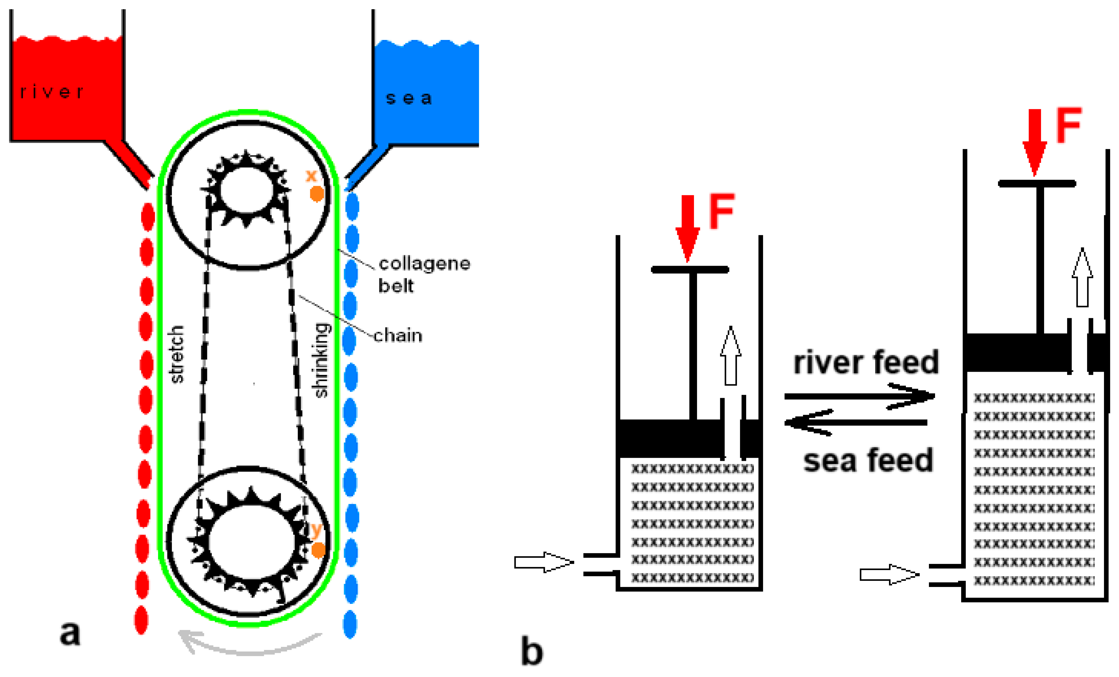
Five years before Loeb’s PRO patent, Sussman and Katchalsky published a paper titled “Mechanochemical Turbine, A new power cycle” [38]. The authors constructed a working SGE machine based on the shrinking of a crosslinked collagen cord in salt water; it returned to its original length in fresh water. Figure 5a shows a simplified model of their generator. In 2014, Zhu et al. published a paper describing their experiments with a hydrogel in a cylinder that could push a piston away as it swelled upon contact with fresh water and shrank again upon the introduction of salt water (Figure 5b) [39].
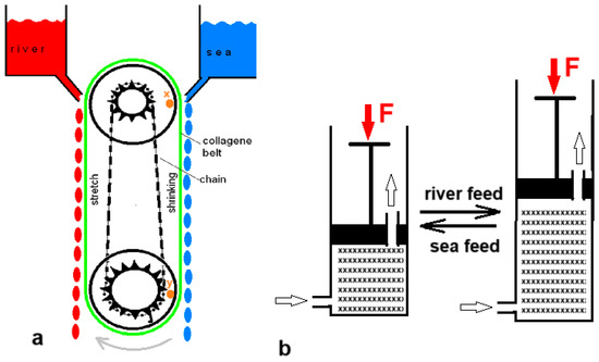
Figure 5.
Swelling–shrinking methods: (a) Simplified model of the mechanochemical turbine. The collagen belt (green) is shrinking if in contact with seawater. This sets the system in motion: the wheels will turn clockwise. The chain (black) causes the upper pully to turn faster so that the distance between point x on the upper pully and point y on the lower pully is getting smaller. This corresponds to belt shrinkage. (b) Cylinder and piston model generating SGE by swelling and shrinking of a hydrogel.
2.3. Diffusion of Water Vapor
In 1979, Olsson et al. published a paper entitled Salinity Gradient Power: Utilizing Vapor Pressure Differences [40]. The method—known as VPDU—is based on the difference in the vapor pressure of fresh and salt water. Water vapor will find its way from the fresh water to the salt water (Figure 6d). The researchers tested this principle in a vacuum chamber in which a turbine was placed in the vapor stream. The heat of condensation in the salt water was returned to the fresh water via a heat exchanger, largely compensating for the significant heat of evaporation. The method has not been followed-up to date.

Figure 6.
Batch processes. (a) Mixing solutions by removing the partition. (b) A single cell pair of an RED stack. (c) A model of a batch PRO device. A piston made of a semi-permeable membrane is pushed upwards by the osmosis of the water to the lower vessel. (d) Principle of VPDU where water vapor flows from the fresh water to the salty compartment. Good heat transfer through the copper septum is essential. (e) Results of Post et al. [41] with two RED stacks, one equipped with 0.5 mm spacers and one with 0.2 mm spacers. The energy yield is calculated based on the theoretical value for the reversible mixing of non-ideal solutions. The solid lines are parabolic regression lines.
3. Exergy of Different SGE Processes
Suppose we mix NaCl solutions of equal volume (1 L) and the same temperature (25 °C). One solution, which we will call “river water”, contains 1 g/L and the other (sea water) contains 30 g/L. If these solutions are mixed isothermally, the free enthalpy changes as follows:
If the solutions are supposed to be ideal, the change in enthalpy ΔH is equal to zero. If the solutions are also mixed reversibly, an amount of work can be harvested equal to
ΔS can be calculated as
The individual entropies can then be calculated from
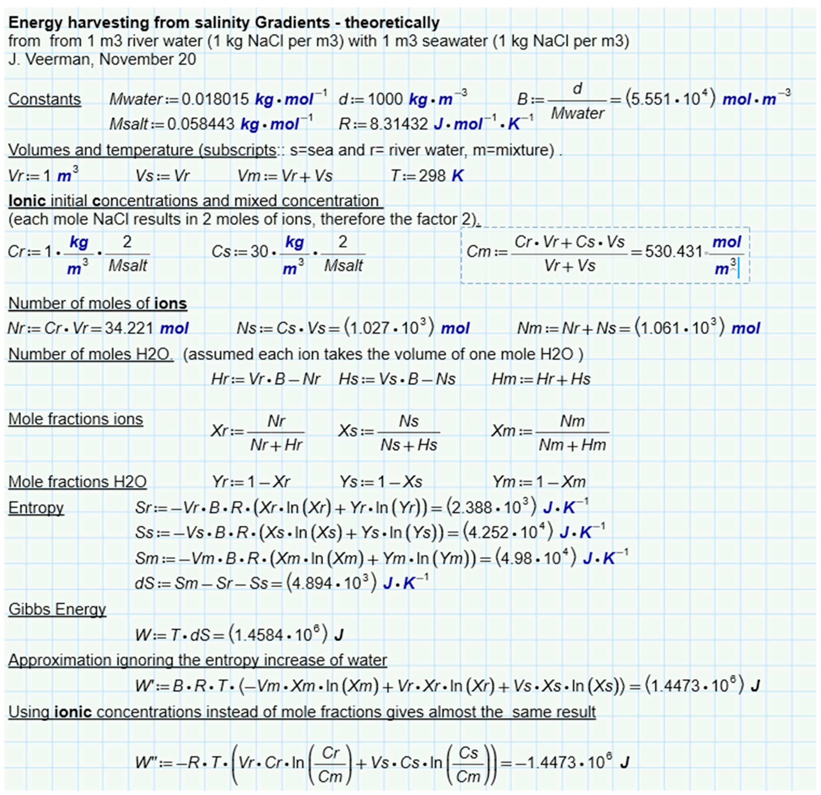
The calculation is presented in Figure 7. It follows that 1.4485 MJ is available due to the increase in entropy from ions and water. If only water is considered, this amount is a little less (1.4473 MJ). In this approach, the ideality of the solutions is assumed. Post et al. corrected these values for the nonideal behavior of the solutions and found that 88% of the ideal value is available in reality [41]. The same authors also performed batch processes with RED with two types of spacers (0.2 mm and 0.5 mm). In these experiments, most of the calculated energy was harvested, especially at low current densities where reversibility is best approximated. Figure 6e shows the results and from the regression lines, a recovery at extreme low current density is expected at about 85% of the available energy.
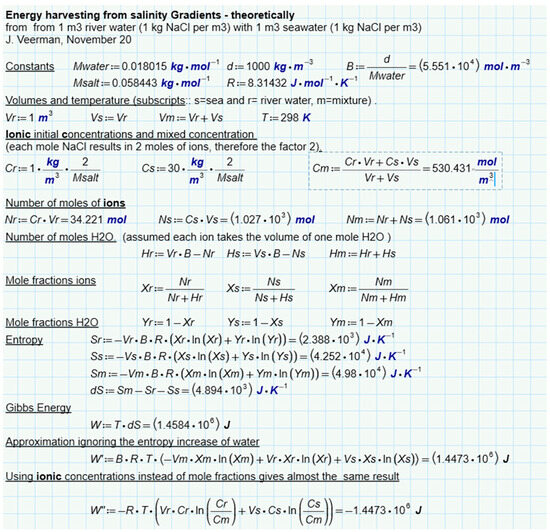
Figure 7.
Theoretical amount of energy harvested from river water and seawater. Assumed is an isothermal process with ideal solutions of NaCl in water.
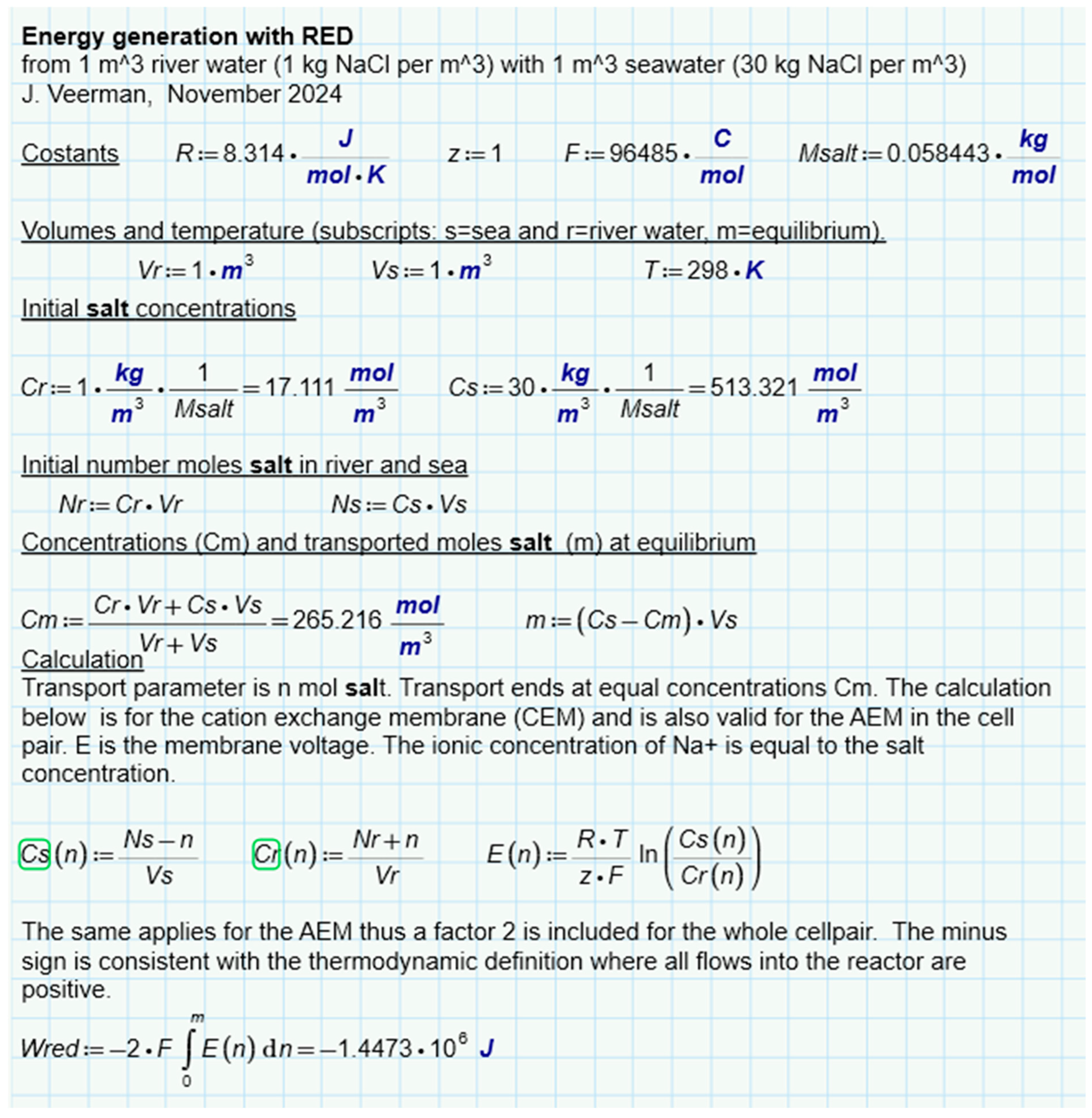
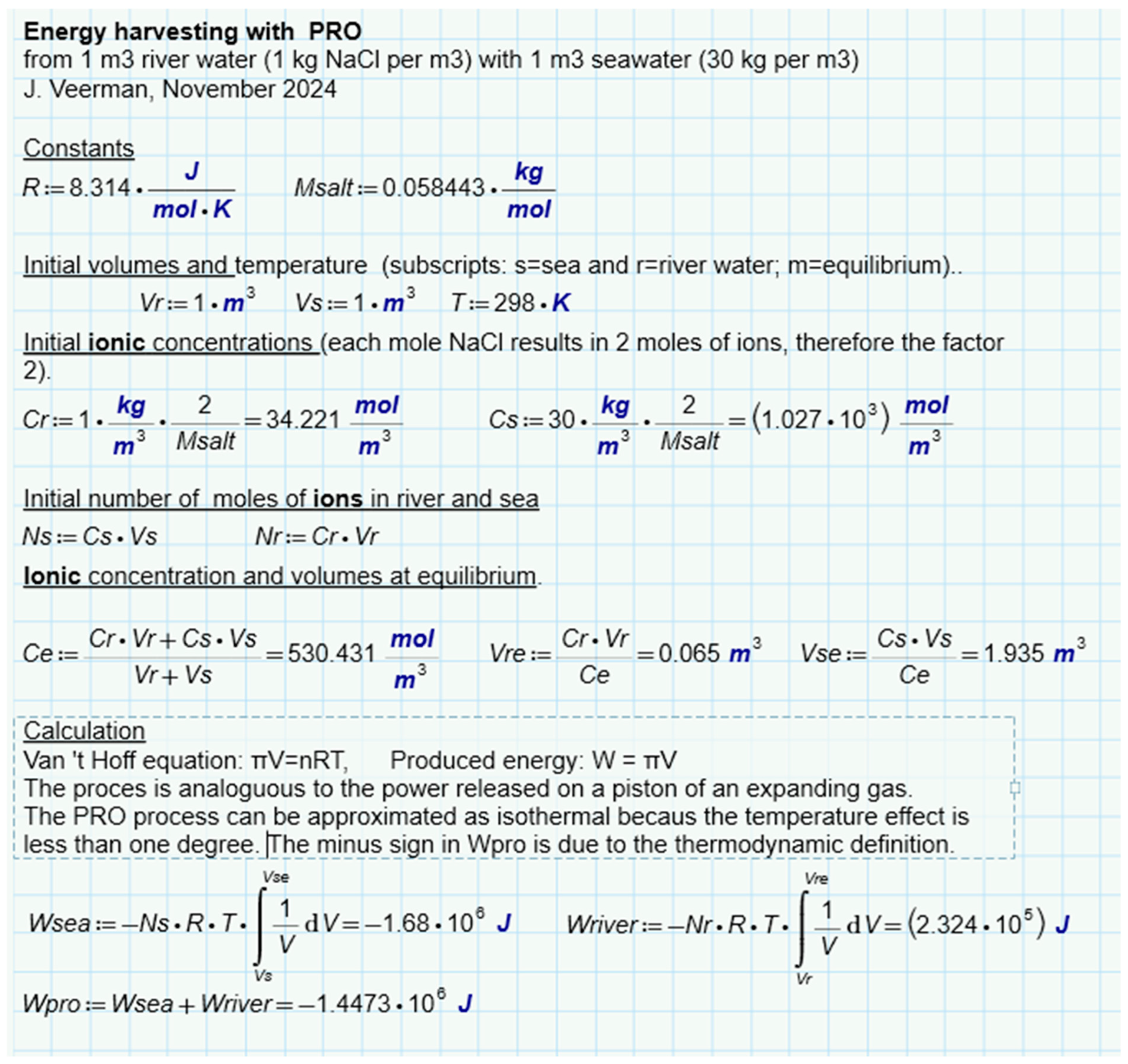
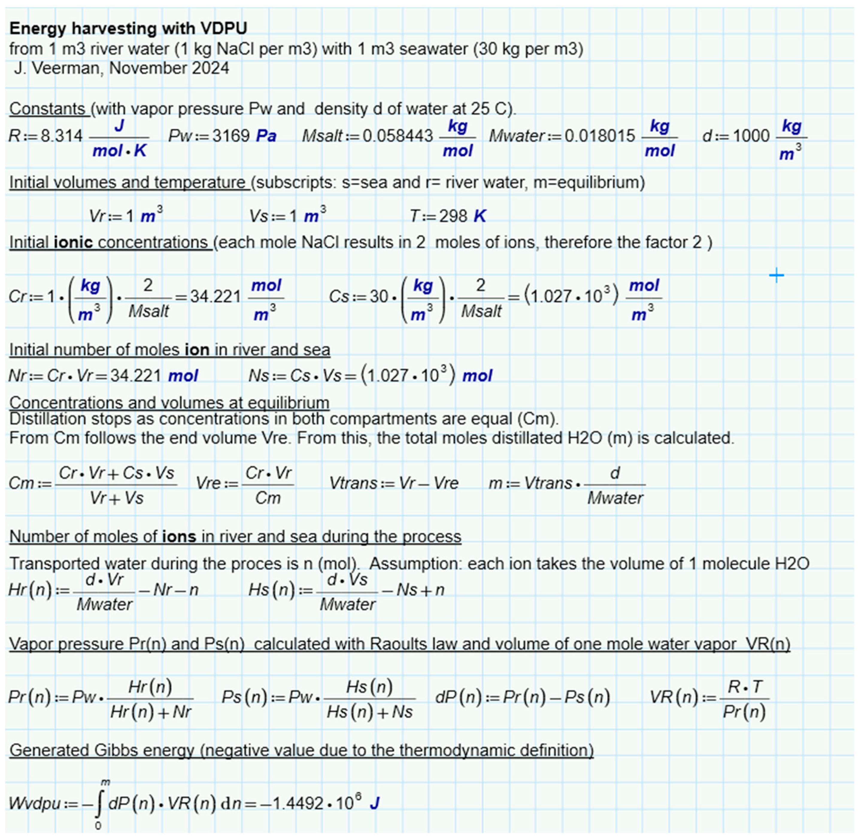
An interesting question is whether there is a difference between the different methods of SGE harvesting, namely by the diffusion of ions, liquid water, or water vapor. For this purpose, we have analyzed batch processes for three representatives (RED, PRO, and VDU) in which a combination of 1 m3 feed waters of 1 and 30 g per liter was always used exhaustively—Figure 6b–d. Ideal solutions were always assumed in the calculation. The results for RED (Figure 8), PRO (Figure 9), and VPDU (Figure 10) lead to a great mutual agreement and are in all cases almost the same as the theoretical model that only considered the entropy of the ions (Table 1). The agreement is surprising because the various derivations are based on very different theories: the theoretical derivation uses the increase in entropy, RED is based on Nernst’s law, PRO focuses on Van’t Hoff’s law, while VPDU uses Raoult’s law.
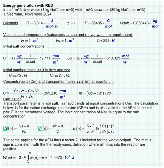
Figure 8.
SGE of RED. Modeled for a batch process where the feed waters are used exhaustively. Cs(n) and Cr(n) are the salt concentrations after transport of n mol of salt.
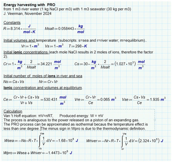
Figure 9.
SGE of PRO. Modeled for a batch process where the feed waters are used exhaustively.
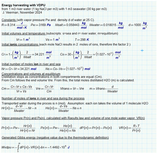
Figure 10.
SGE of VPDU. Modeled for a batch process where the feed waters are used exhaustively.

Table 1.
Comparison of the energy amount, theoretically and with different harvesting methods.
4. Applications of SGE
As mentioned earlier, it was Manecke who first reported a form of SGE in his “Membrane Accumulator” in 1952, using an RED/ED stack for electricity storage. Nowadays, SGE finds applications in many areas and much of the literature is available. We limit ourselves to mentioning some recent reviews: for PRO, we refer to Gonzalez et al. [42] and to Sharma et al. [43]; for RED, we refer to Mei and Tang [44] and to Gül et al. [45]. A general review about SGE is the article of Han et al. [46]. In the following overview, we will discuss some lesser known applications in more detail.
4.1. Energy Generation
The largest reservoir of SGE is formed by the rivers in cooperation with the sea and it is therefore not surprising that this aspect has been studied most with regard to both to RED and PRO. However, applications at the level of pilot installations have been limited so far and the actual effort presents so many challenges that some authors consider it as impossible [47]. We will mention two examples of PRO and two of RED on a pilot scale.
- -
- The PRO installation of Statkraft in Tofte, Norway. The installation, which started in 2009, had a capacity of 2–4 kW [48]. However, the performance/price ratio was not high enough to be economically viable, and the project was terminated in 2014 [49].
- -
- The use of highly concentrated salt solutions ensures that more energy can be harvested per m2 of membrane so that PRO can still be made possible on an industrial scale [50]. This is the approach of the company Saltpower in Denmark. The brine is extracted by leaching from deep salt layers. The caverns thus created can then serve as storage for natural gas or hydrogen [51,52].
- -
- In Trapani (Sicily, Italy), a project ran in which RED power was extracted from brackish water and brine. With artificial solutions, 700 W was gained. With natural solutions from the saltworks, the output power dropped to 50%, which was ascribed to the influence of multivalent ions] [53,54].
- -
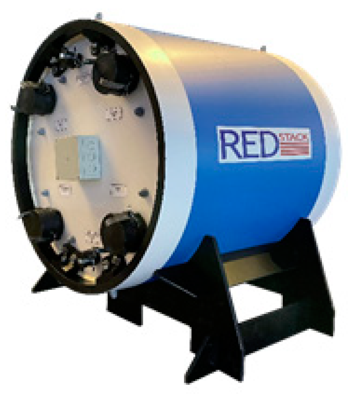
- In the Netherlands, an RED pilot was constructed at the closure dam between the Lake IJssel and the Wadden Sea with an infrastructure enabling the installation of 50 kW RED stacks [3,55,56]. The company REDstack BV is developing the whole process technology and also the development and manufacturing of their own innovative cross-flow stacks (Figure 11).
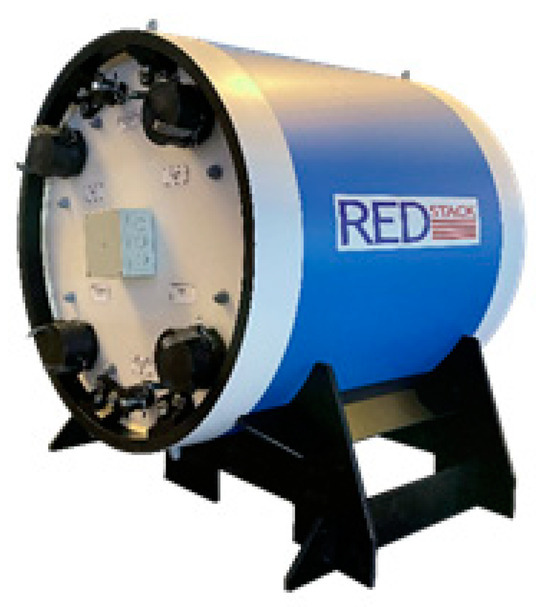 Figure 11. A cross-flow RED stack, also suitable for ED [3]. The cylindrical casing contains a cubic cross-flow stack. The four half-moon shaped compartments between the stack and the casing are used for the supply and discharge of the feed waters.
4.2. Desalination
SGE is based on mixing salt and fresh water and applications for desalination seem counterintuitive. However, there are two applications that can be used for desalination purposes, namely direct coupling and assisted reverse electrodialysis (ARED).
4.2.1. Direct Coupling
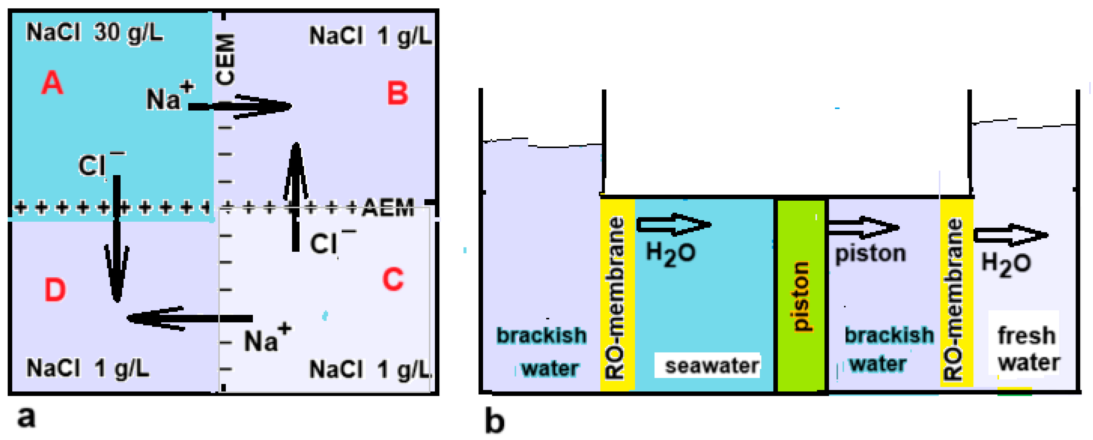
As previously reported, Murphy managed to desalinate water with a device based on a direct coupling between RED and ED [20]. Direct coupling or RED and ED were also studied by Veerman [21] and by Cheng et al. [57]. A ring-shaped stack even makes it possible to make such a system without electrodes, as seen in Figure 12a. Osterle and Feng have also proposed something similar for the coupling between PRO and RO [58]. In their idea, both techniques work with pistons that are coupled to each other (Figure 12b).
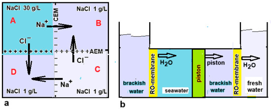
Figure 12.
(a) Top view of a setup for the direct coupling between RED and ED. The vessels D, A, and B form the RED part, while B, C, and D represent the ED unit. The process stops when the EMFs of both systems are equal. Starting with NaCl concentrations of 30 g/L in A and 1 g/L in B and C, then 0.88 g/L NaCl can be transported from A and from C to B and D under ideal conditions, resulting in a final concentration in D of 0.12 g/L. Due to the cyclic structure, no electrodes are required [21]. (b) Direct coupling as suggested by Osterle and Feng [58]. The left two vessels are the driving part: by diffusion of water to the seawater compartment, the piston is driven to the right. Therefore, water from the adjacent compartment is forced through the RO membrane and this results in the production of fresh water in the rightmost compartment.
4.2.2. Assisted RED (ARED)
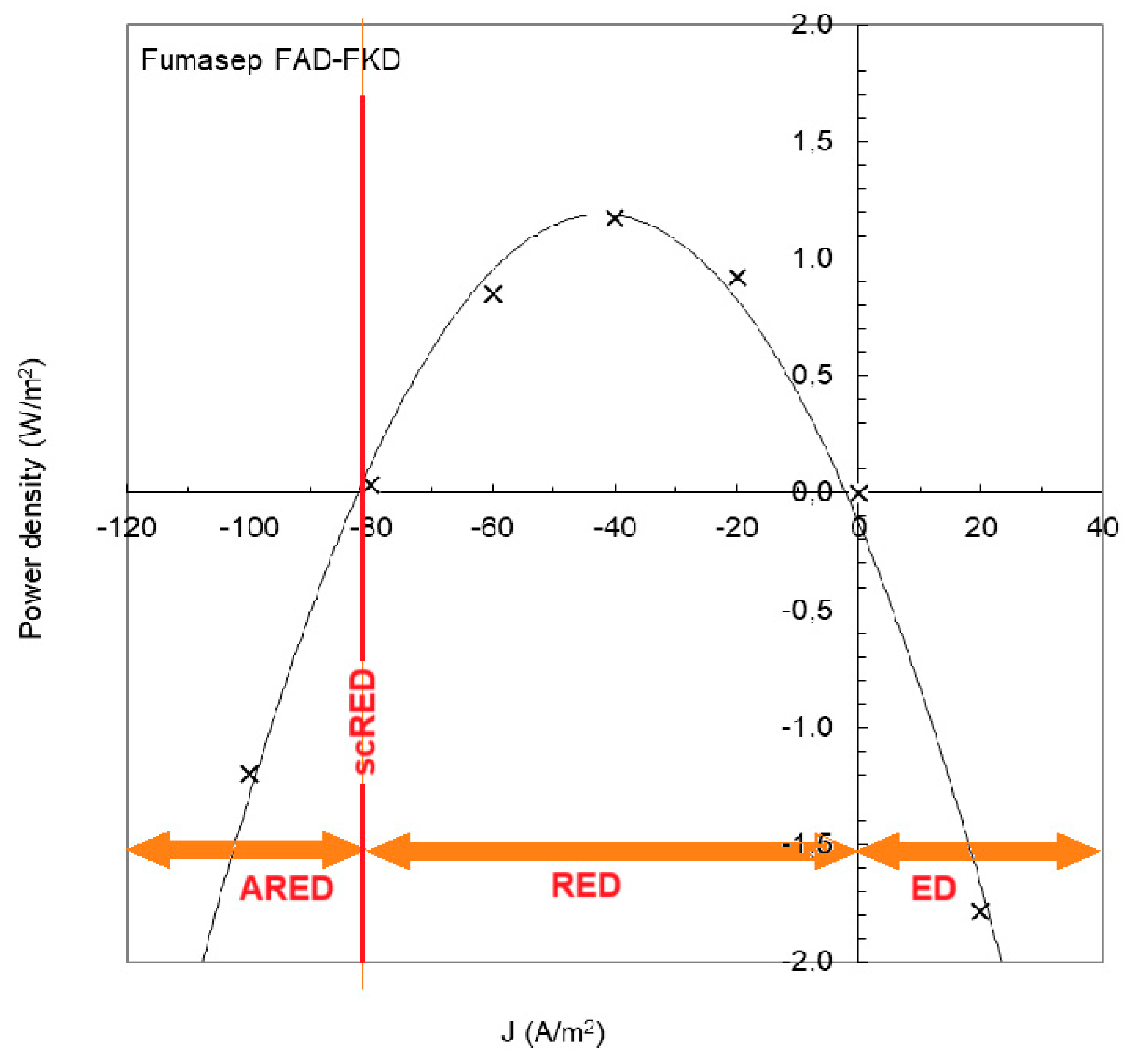
Figure 13 shows an experiment with an RED stack equipped with Fumasep membranes (FAD and FKD) [59]. If the current density is below −82 A/m2, the RED process requires the input of energy and is called “assisted reverse electrodialysis” (ARED); above 0 A/m2, normal electrodialysis (ED) occurs. With ARED, salt transport occurs from high concentration to low concentration, the same direction as in RED. Transport by ARED costs considerably less energy than ED. In the figure, it is seen that ARED at −100 A/m2 costs about the same amount of energy as ED at 20 A/m2; therefore, five times more mass transport takes place with ARED than with ED.
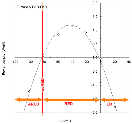
Figure 13.
RED experiment with Fumasep membranes. Power is produced at a current density between −82 and 0 J/m2. At a lower current density, the RED process requires the input of energy (assisted RED, ARED) and with higher values, we are dealing with normal electrodialysis (ED). A special case is when the stack is short-circuited, indicated by scRED. The plot is extracted from Figure 7a in [59]. Measured data (X) are fitted with a parabolic regression line.
A special opportunity is shortcut RED (scRED), whereby the electrodes of the stack are short-circuited. This is the situation at −82 A/m2 in Figure 13. The stack now functions as a regular dialyzer and the advantage is—apart from the energy neutrality—that no external circuitry is required [60].
If a city located on the coast depends on a seawater RO desalination unit (SWRO) for its drinking water, then that city will also discharge a quantity of wastewater into the sea that is comparable to the production of the SWRO. This low-salinity outflow of the SWRO can be used together with the inflow of the RO to feed an RED unit. This has two advantages, namely that the RO operates with less energy due to the lower inlet concentration and, in addition, the RED unit energy.
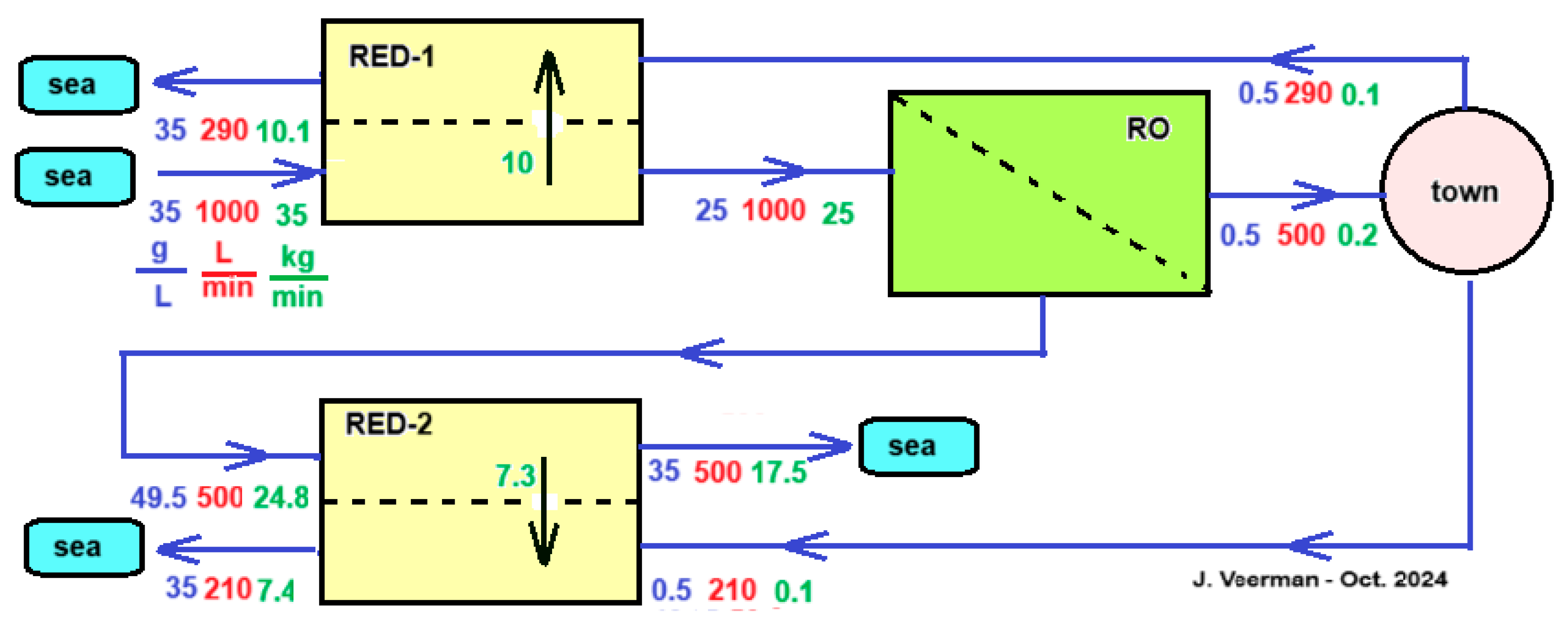
Vanoppen et al. analyzed this system and came to the conclusion that the profit of the RO part is much greater than the energy supplied by the RED [61]. It is therefore worth considering assisting the salt transport in the RED part by an imposed voltage that thus helps the ions in the direction from high to low concentration—exactly the opposite of the case with ED shown in Figure 13. Although this assisted RED technology (ARED) costs energy, the profit in the RO part more than compensates for this. Figure 14 shows a concept of an integrated system of RO, ARED, and RED for the production of potable water to a town. It is simplified in some aspects; it is assumed that the flow rate of the produced sewage of the town equals the consumed drinking water flow rate and the treatment of inlet seawater and outlet sewage from the town are omitted.
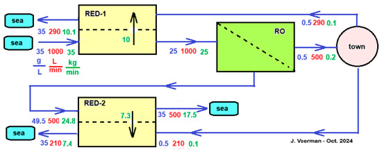
Figure 14.
Concept of an RED-RO-RED configuration. A city with 5000 inhabitants receives 500 L of drinking water per minute, i.e., 144 L per person per day. It is assumed that the city’s sewage has the same salinity and flow rate as the incoming drinking water. Pre-filtration of the used seawater is ignored for simplicity, and the same applies to the cleaning of the sewage. The RED-1 module can be operated as normal RED, but more efficiently as ARED. The city’s wastewater is divided between RED-1 and RED-2. In this example, the division is adjusted so that all flows to the sea have salinities equal to those of the sea. In the scheme, blue numbers represent salt concentrations (g/L), red are flow rates (L/min), and green are salt transport rates (kg/min).
As mentioned, the main function of the module RED-1 in Figure 14 is to reduce the salt inflow into the RO section. Other options than the use of RED that are worth investigating further are to place a regular dialyzer here, equipped with an ultrafiltration, nanofiltration, or mosaic membrane. Due to the salt gradient, there will be a tendency for a salt flow downwards and a water flow upwards. Both flows influence each other; with mosaic membranes, there is even a chance of negative osmosis [62,63].
4.3. Production of Gasses H2 and O2
If inert electrodes and an electrode rinse with NaCl but without a redox couple are chosen for RED, H2 will be developed at the cathode and Cl2 and/or O2 at the anode [13]. This H2 is a marginal by-product in a stack with many cell pairs but can also be a main product in a modified stack design. An RED stack with approximately 50 cell pairs and fed with solutions of 1 and 30 g/L yields an OCV of about 6 V in practice [64], while about 2–3 V is required for the electrolysis of water (1.23 V Nernst voltage and an overvoltage depending on electrode material, temperature, and current density). If a similar cell is short-circuited, there will only be gas development without electricity production. The generation of H2 and O2 was already described by Weinstein and Leitz in 1976 [65]; however, Logan et al. managed to obtain a patent on this in 2014 [66] and various publications on the subject appeared in the years that followed. Electrolysis can occur in an external electrolyzer [67] or on the electrodes of the RED stack [68,69,70]. In addition to salinity gradients as a primary exergy source, temperature differences can also be used to drive an RED generator. Sollberg et al. described a combination of such a heat-to-power system in which the RED stack generated hydrogen using waste heat [71].
4.4. Decomposition and Synthesis of Chemicals
In a classical RED stack (without capacitive electrodes), electrode reactions take place, with oxidation at the anode and reduction at the cathode. By passing polluted water through the electrode compartments, chemicals can be rendered harmless. Examples are the oxidation of Acid Orange 7 mainly to biodegradable carboxylic acids [72] and the reduction of chromium(VI) to Cr(III) [73]. Besides removing unwanted substances, the electrode compartments can also be used for the electrosynthesis of desired chemicals [74].
4.5. Energy Storage
In order to tackle the climate crisis, a large-scale transition from fossil fuels to renewable sources is being made. However, the two most important ones—solar and wind—are very variable and pose major challenges for energy suppliers. Solutions are dynamic energy contracts, expansion of the network, and energy storage. The latter can be achieved by creating salinity gradients and using them for electricity generation. This can be performed electrically (ED with RED) or based on pressure (RO with PRO).
4.5.1. Electric Systems
Classical electric batteries have their solid or liquid electrolytes together with the electrodes in the same housing and therefore have a limited storage capacity. This is in contrast to flow batteries (FBs), which have their liquid electrolytes stored externally and therefore have an arbitrarily large capacity but a lower specific energy (in kWh/kg), which makes them especially suitable for stationary applications. FBs are based on redox reactions, acid–base reactions, or salinity gradient energy. The vanadium redox flow battery (VRFB) is reasonably well developed and has a specific energy of approximately 20 Wh/kg.
The concentration battery is in fact the forefather of the salinity gradient energy through the work of Manecke [12] but received renewed interest about ten years ago. The modern concentration gradient flow battery (CGFB) is essentially a combination of ED (for charging) and RED (for production). Experiments by Van Egmond et al. have shown that this is possible, but the specific energy is initially rather low (0.3 Wh/kg) [75,76].
The latest addition to the flow battery branch is the acid–base flow battery (ABFB). The heart of this technique is a bipolar membrane in which water is dissociated during charging and the H+ and OH− ions recombine into water during discharging. This emerging device has a reported specific energy of 10 Wh/kg [77] or even 17 Wh/kg [78] and also has advantages in terms of the environment and cost price [79]. Given the rapid developments of the ABFB, it is to be expected that the ABFB has more potential than the CGFB and will become a formidable competitor for the VRFB.
4.5.2. Pressure Systems
Besides ED/RED, SGE can also be stored with RO/PRO [80,81]. In principle, storage and recovery can be performed with the same device. To our knowledge, no real experiments have been performed so far in which a complete cycle was tested. As mentioned in Section 4.5.1, the energy content of salt gradients is quite small. With electrical methods, the step was made to the acid/base battery by using a bipolar membrane, but this is not possible with ED/PRO, and it is questionable whether there is a future for an ED/PRO system based on salt gradients.
4.6. RED Heat Engine
There are many methods to produce mechanical or electrical energy using temperature differences, e.g., with Peltier elements or with the Stirling engine. This conversion of heat to power is also possible with RED by using closed loops of feed waters that are regenerated after passing through the stack. The maximum achievable yield of all these techniques is determined by the Carnot efficiency:
where Th is the temperature of the heat source and Tc of the heat sink (both in K). For a waste heat of 100 °C together with a condenser temperature of 20 °C, this results in a Carnot efficiency of 21%. A system efficiency of 50% would be achievable with a good design, resulting in a gross efficiency of about 10% [82]. Globally, there is a large supply of hot waste water. Papapetrou et al. arrived at a thermal equivalent of 480 TWh/year (a mean power of 51 GW) of water of approximately 100 °C, mainly of industrial origin [83].
In the framework of the EU project RED-Heat-to-Power (the European Union’s Horizon 2020 research and innovation program under grant agreement no. 640667), a consortium of seven participants worked on the realization of an RED heat engine during the years 2015–2019 [83]. Tamburini et al. described the principle of the RED heat engine from which we summarize the main points below [84]. The RED heat engine works with closed loops of feed waters: one with high (HC) and the other with low salt concentration (LC). After passing through the RED stack, the concentrations and flow rates are returned to the original values in a regenerator. This can be achieved in the following two ways:
- (i).
- A volatile salt is extracted from the LC stream by heating and added to the cold HC stream. Ammonium bicarbonate or ammonium carbonate are suitable salts that decompose at elevated temperature (Figure 15b):
 Figure 15. RED heat engines. (a) With a distillation regenerator; (b) with ammonium(bi)carbonate evaporator.
NH4HCO3 → NH3 + H2O + CO2
(NH4)2CO3 → 2 NH3 + H2O + CO2
- (ii).
- Water is extracted from the HC stream by distillation and added to the LC stream. The choice of salt is fairly free in this case (Figure 15a).
The final conclusion of the project was that multiple effect distillation is the best option [83].
4.7. Transdermal Drug Delivery
Transdermal drug delivery is the administration of medicines or other substances through the skin using prepared patches. These substances penetrate the skin through diffusion and enter the bloodstream. The process is relatively slow, and the speed is strongly dependent on the molar mass, with a practical limit of 300 Da being used [85]. By applying a voltage difference across a piece of skin, this process can be greatly accelerated, especially if the molecules have an electrical charge. With this, the so-called iontophoresis administering drugs with a molar mass of 13 kDa is possible.
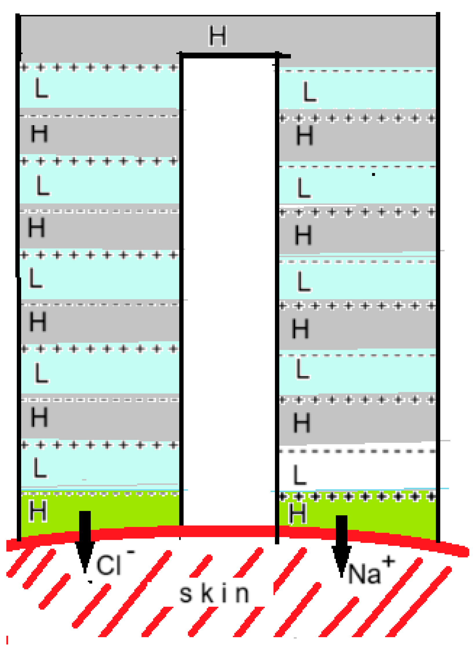
A new development is to generate this voltage with an electrodeless RED system that is integrated into a patch. Kwon et al. described such a system in which the RED stack has an inverted U-shape and both ends lie on the skin, as shown in Figure 16 [22]. Depending on the charge, the drug is applied to the gel layer of one of the ends. The researchers compared the uptake rate of a number of substances in this system with a classic diffusion-driven gel patch and found that their RED system was much more active.
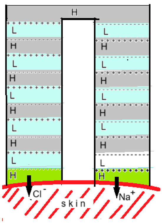
Figure 16.
The RED gel patch according to Kwon et al. [22]. AEMs are indicated by + + + and CEMs by - - -. Compartments with an H contained a saline solution of 4.4 M and those with an L a solution of 0.011 M so that the concentration ratio was 400. With 10 cell pairs, an OCV of 2.4 V was generated. The cell was tested on prepared mouse skin with risedronate (anionic) and with ketorolac tromethamine and lidocaine (both cationic). Positive drugs were applied as gel to the right side and negative ones to the left side of the device in the figure.
4.8. Drainage of Lowlands near the Sea
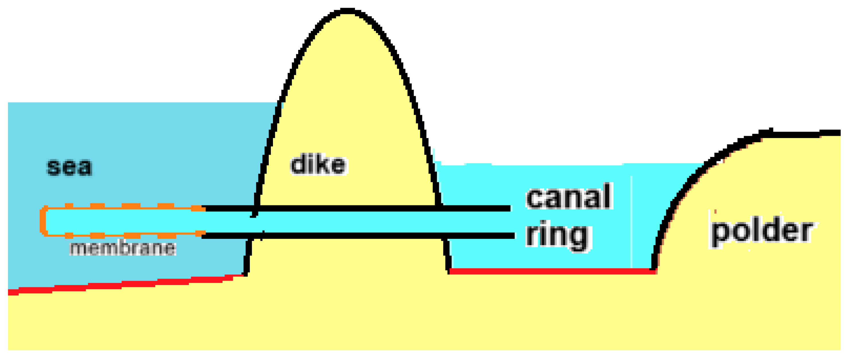
A large part of the Dutch coastal provinces lies below sea level, with the lowest polder water level being up to 7 m below the average sea level. Pumping stations ensure the discharge of water to the sea and require a lot of energy, which will increase in the future with the rise in sea level. The osmotic pressure of seawater is about 25 bar, which corresponds to a water column of 250 m. By replacing the dikes with RO membranes in these conditions, dewatering could be performed without energy input. Gerrit Oudakker patented this concept where the membrane was placed in the sea, as shown in Figure 17 [86]. He also mentioned the possibility of extracting energy from this process with a generator placed near the outlet in the sea. In fact, only a small part of the available energy is needed to pump the water to the sea, which is why the idea arose to place the PRO generator on land as a more practical place than in the sea [87]. Such an osmotic power plant was given the name “osmaal”, a portmanteau of “osmotic” and “gemaal”, the Dutch word for pumping station.
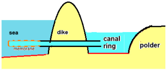
Figure 17.
Principle of the osmaal: diffusion from polder water through modified RO membranes to the sea. The lowest polder level in the Netherlands is approximately 7 m below sea level, while the osmotic pressure difference between sea and the water in the canal ring around the polder is approximately 25 bar, corresponding to a water column of 250 m. This is more than sufficient for the osmotic transport of polder water to the sea.
5. Conclusions and Outlook
Techniques that can harvest SGE are based on the diffusion of ions (mainly RED), liquid water (mainly PRO), or water vapor (VPDU). Theoretically, the available amount of extractable energy with all these techniques is the same, but in practice, only RED and PRO have practical significance until now.
SGE systems can be open or closed. In an open system such as blue energy—the energy that is extracted from rivers and seawater—the composition of the feed water is fixed and the system should be adjusted accordingly to the ionic composition of the feed waters. On the other hand, in closed systems, the technique dictates the choice of the salt. For energy storage systems, large quantities are needed, and the cost price and environmental aspects are the most important factors, while the RED heat engine requires salts that are directly linked to the technique in question (salt extraction or water evaporation). In addition to salt, the feed water in open systems can also contain organic substances that can lead to membrane contamination but also offer possibilities as fuel for the microbial reverse electrodialysis cell (MRC).
The energy content of salt gradients is quite low and that means that a lot of water has to be fed through the SGP generators to achieve reasonable energy production. This places high demands on the design because the power for pumping and pretreatment must of course be less than the delivered power. Scaling up places very high demands on the design of generators, on the entire infrastructure, and on the development of affordable membranes. However, the development of RED and PRO has also led to spin-offs in terms of the development of new types of membranes and therefore, RED and PRO are also of significance for the two predecessors, namely ED and RO [88].
What is interesting are the developments that have led to scaling down. Examples are the RED-based transdermal drug delivery systems. Completely new are the ideas to build RED generators into the human body as an energy source for pacemakers, insulin pumps, or other medical devices. Initial experiments have been performed on harvesting energy from the difference in salinity of the renal vein and renal artery [89] or from the enormous differences in pH between the stomach wall (pH = 7.5) and stomach juice (pH = 1.5) [90].
To conclude the outlook in this article, let us look back. Earlier, we said that SGE started in 1952 with the experiments of Manecke, but we actually have to adjust this idea. Japanese researchers have recently demonstrated that the process of SGE also plays a role in the walls of the chimneys on deep sea submarine vents [91]. These contain pores that selectively allow Na+, K+, H+, and Cl− to pass through. The potential differences generated by this on the outside then ensure the transport of larger divalent ions towards the wall, where they precipitate. Closed nanopores are created inside the walls, and these may have played a role in the origin of life 3.7 billion years ago.
Funding
This research received no external funding.
Data Availability Statement
The original contributions presented in the study are included in the article; further inquiries can be directed to the corresponding author.
Acknowledgments
This work was facilitated by REDstack BV in The Netherlands. REDstack BV aims to develop and market RED and the ED technology. The author would like to thank his colleagues from the REDstack company for fruitful discussions and especially Folkert van Beijma for his linguistic advice.
Conflicts of Interest
Joost Veerman was employed by REDstack bv. The author declares no conflicts of interest.
Abbreviations
| ABFB | acid base flow battery |
| AC | activated carbon |
| AEM | anion exchange membrane |
| ARED | assisted RED |
| BDI | battery electrode deionization |
| CapMix | capacitive energy extraction by mixing feedwaters |
| CDLE | CapMix based on double layer expansion |
| CDP | CapMix based on Donnan potentials |
| CGFB | concentration gradient flow battery |
| CEM | cation exchange membrane |
| CRED | capacitive RED |
| CDI | capacitive deionization |
| ED | electrodialysis |
| EMF | electromotive force |
| ERS | electrode rinse solution |
| FB | flow battery |
| HC | high concentration |
| IEM | ion exchange membrane |
| LC | low concentration |
| MEC | microbial electrolysis cell |
| MRC | microbial reverse electrodialysis cell |
| OCV | open-circuit voltage |
| PRO | pressure-retarded osmosis |
| RED | reverse electrodialysis |
| RO | reverse osmosis |
| scRED | shortcut RED |
| SGE | salinity gradient energy |
| VPDU | vapor pressure difference utilization |
| VRFB | vanadium redox flow battery |
References
- Wick, G.L.; Schmitt, W.R. Prospects for renewable energy from sea. Mar. Technol. Soc. J. 1977, 11, 16–21. [Google Scholar]
- World Energy Outlook 2024. International Energy Agency. 2024. Available online: https://www.iea.org/reports/world-energyoutlook (accessed on 13 February 2025).
- B. V. REDstack. Available online: www.redstack.nl (accessed on 10 October 2024).
- Schunke, A.J.; Herrera, G.A.H.; Padhye, L.; Berry, T.-A. Energy recovery in SWRO desalination: Current status and new possibilities. Front. Sustain. Cities 2020, 2, 9. [Google Scholar] [CrossRef]
- Li, J.; Zhang, C.; Wang, Z.; Wang, H.; Bai, Z.; Kong, X. Power harvesting from concentrated seawater and seawater by reverse electrodialysis. J. Power Sources 2022, 530, 231314. [Google Scholar] [CrossRef]
- Xu, P.; Cath, T.Y.; Robertson, A.P.; Reinhard, M.; Leckie, J.O.; Drewes, J.E. Critical review of desalination concentrate management, treatment and benefical use. Environ. Eng. Sci. 2013, 30, 502–514. [Google Scholar] [CrossRef]
- Loeb, S. One hundred and thirty benign and renewable megawatts from Great Salt Lake? The possibilities of hydroelectric power by pressure-retarded osmosis. Desalination 2001, 141, 85–91. [Google Scholar] [CrossRef]
- Loeb, S. Energy production at the Dead Sea by pressure-retarded osmosis: Challenge or chimera? Desalination 1998, 120, 247–262. [Google Scholar] [CrossRef]
- Huang, F.Y.C.; Martinez, A.D.; Wei, Q. Beneficial use of highly saline produced water in pressure-retarded osmosis. Environ. Eng. Sci. 2018, 35, 472–483. [Google Scholar] [CrossRef]
- Abbas, T.; Al-Furaiji, M. Use of reverse electrodialysis to harvest salinity gradient energy from oilfield produced water. Pollution 2021, 7, 943–957. [Google Scholar] [CrossRef]
- Cosenza, A.; Campisi, G.; Giacalone, F.; Randazzo, S.; Cipollina, A.; Tamburini, A.; Micale, G. Power production from produced waters via reverse electrodialysis: A preliminary assessment. Energies 2022, 15, 4177. [Google Scholar] [CrossRef]
- Manecke, G. Membranakkumulator. Z. Für Phys. Chem. 1952, 201, 1–15. [Google Scholar] [CrossRef]
- Veerman, J.; Saakes, M.; Metz, S.J.; Harmsen, G.J. Reverse electrodialysis: Evaluation of suitable electrode systems. J. Appl. Electrochem. 2010, 40, 1461–1474. [Google Scholar] [CrossRef]
- Jiang, Y.; Alhassan, S.I.; Wei, D.; Wang, H. A review of battery materials as CDI electrodes for desalination. Water 2020, 12, 3030. [Google Scholar] [CrossRef]
- Xu, Y.; Zheng, S.; Tang, H.; Guo, X.; Xue, H.; Pang, H. Prussian blue and its derivatives as electrode materials for electrochemical energy storage. Energy Storage Mater. 2017, 9, 11–30. [Google Scholar] [CrossRef]
- Ma, F.; Li, Q.; Wang, T.; Zhang, H.; Wu, G. Energy storage materials derived from Prussian blue analogues. Sci. Bull. 2017, 62, 358–368. [Google Scholar] [CrossRef]
- Vermaas, D.A.; Bajracharya, S.; Sales, B.B.; Saakes, M. Clean energy generation using capacitive electrodes in using capacitive electrodes in reverse electrodialysis. Energy Environ. Sci. 2013, 6, 643. [Google Scholar] [CrossRef]
- Wu, N.; Levant, M.; Brahmi, Y.; Tregouet, C.; Colin, A. Mitigating the influence of multivalent ions on power density performance in a single membrane capacitive reverse electrodialysis cell. Sci. Rep. 2024, 14, 16984. [Google Scholar] [CrossRef] [PubMed]
- Simões, C.; Saakes, M.; Brilman, D. Toward redox-free reverse electrodialysis with carbon-based slurry electrodes. Ind. Eng. Chem. Res. 2023, 62, 1665–1675. [Google Scholar] [CrossRef]
- Murphy, G.W. Osmotic demineralization. Ind. Eng. Chem. 1958, 50, 1181–1188. [Google Scholar] [CrossRef]
- Veerman, J. Rijnwater ontzouten hoeft geen energie te Kosten. PolyTechnisch Tijdschr. Waterbehandeling 1994, 9, 52–55. [Google Scholar]
- Kwon, S.-R.; Nam, S.H.; Park, C.Y.; Baek, S.; Jang, J.; Che, X.; Kwak, S.H.; Choi, Y.-R.; Park, N.-R.; Choi, J.-Y.; et al. Electrodeless reverse electrodialysis patches as an ionic power source for active transdermal drug delivery. Adv. Funct. Mater. 2018, 28, 1705952. [Google Scholar] [CrossRef]
- Brogioli, D. Extracting renewable energy from a salinity difference using a capacitor. Phys. Rev. Lett. 2009, 103, 058501. [Google Scholar] [CrossRef] [PubMed]
- Sales, B.B.; Saakes, M.; Post, J.W.; Buisman, C.J.N.; Biesheuvel, M.P.; Hamelers, H.V.M. Direct power production from a water salinity difference in a membrane-modified supercapacitor flow cell. Environ. Sci. Technol. 2010, 44, 5661–5665. [Google Scholar] [CrossRef] [PubMed]
- Pandit, S.; Pandit, C.; Mathuriya, A.S.; Jadhav, D.A. Blue energy meets green energy in microbial reverse electrodialysis cells: Recent advancements and prospective. Sustain. Energy Technol. Assess. 2023, 57, 103260. [Google Scholar] [CrossRef]
- Kim, Y.; Logan, B.E. Microbial reverse electrodialysis cells for synergistically enhanced power production. Environ. Sci. Technol. 2011, 45, 5834–5839. [Google Scholar] [CrossRef]
- Mosali, V.S.S.; Soucie, H.; Peng, X.; Faegh, E.; Elam, M.; Street, I.; Mustain, W.E. Mechanistic insights into the electrochemical oxidation of acetate at noble metals. Chem Catal. 2024, 0(0), 1011090. [Google Scholar] [CrossRef]
- Cusick, R.D.; Kim, Y.; Logan, B.E. Energy capture from thermolytic solutions in microbial reverse-electrodialysis cells. Science 2012, 335, 1474. [Google Scholar] [CrossRef] [PubMed]
- Zhu, X.; Hatzell, M.C.; Logan, B.E. Microbial reverse electrodialysis electrolysis and chemical production cell for H2 production and CO2 sequestration. Environ. Sci. Technol. Lett. 2014, 1, 231–235. [Google Scholar] [CrossRef] [PubMed]
- Luo, X.; Zhang, F.; Liu, J.; Zhang, X.; Huang, X.; Logan, B.E. Methane production in microbial reverse-electrodialysis methanogenesis cells (MRMCs) sing thermolytic solutions. Environ. Sci. Technol. 2014, 48, 8911–8918. [Google Scholar] [CrossRef]
- D’Angelo, A.; Galia, A.; Scialdone, O. Cathodic abatement of Cr(VI) in water by microbial reverse-electrodialysis cells. J. Electroanal. Chem. 2015, 748, 40–46. [Google Scholar] [CrossRef]
- Li, X.; Jin, X.; Zhao, N.; Angelidaki, I.; Zhang, Y.N. Novel bio-electro-Fenton technology for azo dye wastewater treatment using microbial reverse-electrodialysis electrolysis cell. Bioresour. Technol. 2017, 228, 322–329. [Google Scholar] [CrossRef] [PubMed]
- Jwa, E.; Yun, Y.-M.; Kim, H.; Jeong, N.; Hwang, K.S.; Yang, S.; Nam, J.-Y. Energy-efficient seawater softening and power generation using a microbial electrolysis cell-reverse electrodialysis hybrid system. Chem. Eng. J. Vol. 2020, 391, 123480. [Google Scholar] [CrossRef]
- Nollet, J.A. Investigations on the causes for the ebullition of liquids. J. Membr. Sci. 1995, 100, 1–3. [Google Scholar] [CrossRef]
- Loeb, S.; Sourirajan, S. High Flow Membrane for Separation Water from Saline Solutions. US Patent US3.133.132A, 12 May 1964. [Google Scholar]
- Loeb, S. Method and Apparatus for Generating Power Utilizing Pressure Retarded Osmosis. US Patent US3906250A, 16 September 1975. [Google Scholar]
- Norman, R.S. Water salination: A source of energy. Science 1974, 186, 350–352. [Google Scholar] [CrossRef] [PubMed]
- Sussman, M.V.; Katchalsky, A. Mechanochemical turbine: A new power cycle. Sci. New Ser. 1970, 167, 45–47. [Google Scholar] [CrossRef] [PubMed]
- Zhu, X.; Yang, W.; Hatzell, M.C.; Logan, B.E. Energy recovery from solutions with different salinities based on swelling and shrinking of hydrogels. Environ. Sci. Technol. 2014, 48, 7157–7163. [Google Scholar] [CrossRef]
- Olsson, M.; Wick, G.L.; Isaacs, J.D. Salinity gradient power—Utilizing vapor-pressure-differences. Science 1979, 206, 452–454. [Google Scholar] [CrossRef]
- Post, J.W.; Hamelers, H.V.M.; Buisman, C.J.N. Energy recovery from controlled mixing salt and fresh water with a reverse electrodialysis system. Environ. Sci. Technol. 2008, 42, 5785–5790. [Google Scholar] [CrossRef] [PubMed]
- Gonzales, R.R.; Abdel-Wahab, A.; Adham, S.; Han, D.S.; Phuntsho, S.; Suwaileh, W.; Hilal, N.; Shon, H.K. Salinity gradient energy generation by pressure retarded osmosis: A review. Desalination 2021, 500, 114841. [Google Scholar] [CrossRef]
- Sharma, M.; Das, P.P.; Chakraborty, A.; Purkait, M.K. Clean energy from salinity gradients using pressure retarded osmosis and reverse electrodialysis: A review. Sustain. Energy Technol. Assess. 2022, 49, 101687. [Google Scholar] [CrossRef]
- Mei, Y.; Tang, C.Y. Recent developments and future perspectives of reverse electrodialysis technology: A review. Desalination 2018, 425, 156–174. [Google Scholar] [CrossRef]
- Gül, T.F.; Akalın, M.; Dönmezler, E.N.; Bolat, A.; Cihanoğlu, A.; Güler, E.; Kabay, N. Review on reverse electrodialysis process-a pioneering technology for energy generation by salinity gradient. Front. Membr. Sci. Technol. 2024, 3, 1414721. [Google Scholar] [CrossRef]
- Han, X.-W.; Zhang, W.-B.; Ma, X.-J.; Zhou, X.; Zhang, Q.; Bao, X.; Guo, Y.-W.; Zhang, L.; Long, J. Review—Technologies and materials for water salinity gradient energy harvesting. J. Electrochem. Soc. 2021, 168, 090505. [Google Scholar] [CrossRef]
- Lin, S.; Wang, Z.; Wang, L.; Elimelech, M. Salinity gradient energy is not a competitive source of renewable energy. Joule 2023, 8, 334–343. [Google Scholar] [CrossRef]
- Patel, S. Statkraft Shelves Osmotic Power Project. Power—News & Technology for the Global Energy Industry. 2014. Available online: https://www.powermag.com/statkraft-shelves-osmotic-power-project (accessed on 3 December 2024).
- ForwardOsmosisTech. Statkraft Bids Farewell to Ambitious Osmotic Power Project. Available online: https://web.archive.org/web/20170118220928/http://www.forwardosmosistech.com/statkraft-discontinues-investments-in-pressure-retarded-osmosis/ (accessed on 3 December 2024).
- Madsen, H.T.; Søndergaard Nissen, S.; Søgaard, E.G. Theoretical framework for energy analysis of hypersaline pressure retarded osmosis. Chem. Eng. Sci. 2016, 139, 211–220. [Google Scholar] [CrossRef]
- Culmsee, J.; Pedersen, L.S.; Guo, H. Worlds first osmotic energy plant for solution mining in operation. In Proceedings of the Solution Mining Research Institute Fall 2023 Technical Conference, San Antonio, TX, USA, 2–3 October 2023; Available online: https://udviklingsaltpower.kinsta.cloud/wp-content/uploads/2025/01/2023-smri-jce.pdf (accessed on 13 February 2025).
- Quintal, J.; Bindseil, M.F.; Nakao, T.; Hirata, S.; Overgaard, M.; Thorøe, K.; Culmsee, J.; Pedersen, L.S.; Guo, H. Full Scale Demonstration of Osmotic Power in High Salinity. Available online: https://udviklingsaltpower.kinsta.cloud/wp-content/uploads/2025/01/2021-euromembrane-2021-abstract-hgo.pdf (accessed on 13 February 2025).
- Tedesco, M.; Cipollina, A.; Tamburini, A.; Micale, G. Towards 1kW power production in a reverse electrodialysis pilot plant with saline waters and concentrated brines. J. Membr. Sci. 2017, 522, 226–236. [Google Scholar] [CrossRef]
- Tedesco, M.; Scalici, C.; Vaccari, D.; Cipollina, A.; Tamburini, A.; Micale, G. Performance of the first reverse electrodialysis pilot plant for power production from saline waters and concentrated brines. J. Membr. Sci. 2016, 500, 33–45. [Google Scholar] [CrossRef]
- IRENA. Salinity Gradient Energy—Technology Brief. Available online: https://www.irena.org/-/media/Files/IRENA/Agency/Publication/2014/Jun/Salinity_Energy_v4_WEB.pdf (accessed on 2 December 2024).
- Veerman, J.; Hack, P.; Siebers, R.; van Oostrom, M. Blue energy from salinity gradients. J. Ocean Technol. 2023, 18, 26–36. [Google Scholar]
- Chen, Q.; Liu, Y.-Y.; Xue, C.; Yang, Y.-L.; Zhang, W.-M. Energy self-sufficient desalination stack as a potential fresh water supply on small islands. Desalination 2015, 359, 52058. [Google Scholar] [CrossRef]
- Osterle, J.; Feng, W.W. Self-energized osmotic desalination. Mech. Eng. 1975, 97, 58. [Google Scholar]
- Veerman, J.; de Jong, R.M.; Saakes, M.; Metz, S.J.; Harmsen, G.J. Reverse electrodialysis: Comparison of six commercial membrane pairs on the thermodynamic efficiency and power density. J. Membr. Sci. 2009, 343, 7–15. [Google Scholar] [CrossRef]
- Gurreri, L.; La Cerva, M.; Moreno, J.; Goossens, B.; Trunz, A.; Tamburini, A. Coupling of electromembrane processes with reverse osmosis for seawater desalination: Pilot plant demonstration and testing. Desalination 2022, 526, 115541. [Google Scholar] [CrossRef]
- Vanoppen, M.; Criel, E.; Walpot, G.; Vermaas, D.A.; Verliefde, A. Assisted reverse electrodialysis—Principles, mechanisms, and potential. npj Clean Water 2018, 1, 9. [Google Scholar] [CrossRef]
- Weinstein, J.N.; Caplan, S.R. Charge-mosaic membranes: Enhanced permeability and negative osmosis with a symmetrical salt. Sci. New Ser. 1968, 161, 70–72. [Google Scholar] [CrossRef] [PubMed]
- Bolto, B.H.M.; Tran, T. Review of piezodialysis—Salt removal with charge mosaic membranes. Desalination 2010, 254, 1–5. [Google Scholar] [CrossRef]
- Veerman, J.; Saakes, M.; Metz, S.; Harmsen, G. Reverse electrodialysis: Performance of a stack with 50 cells on the mixing of sea and river water. J. Membr. Sci. 2009, 327, 136–144. [Google Scholar] [CrossRef]
- Weinstein, J.N.; Leitz, F.B. Electric power from differences in salinity: The dialytic battery. Science 1976, 191, 557–559. [Google Scholar] [CrossRef] [PubMed]
- Logan Bruce, E.; Kim, Y.; D, C.R.; Nam, J. Methods for Hydrogen Production. US Patent US2014/0251819A, 17 January 2017. [Google Scholar]
- Tufa, R.A.; Rugiero, E.; Chanda, D.; Hnàt, J.; van Baak, W.; Veerman, J.; Fontananova, E.; Di Profio, G.; Drioli, E.; Bouzek, K.; et al. Salinity gradient power-reverse electrodialysis and alkaline polymer electrolyte water electrolysis for hydrogen production. J. Membr. Sci. 2016, 514, 155–164. [Google Scholar] [CrossRef]
- Chen, X.; Jiang, C.; Shehzad, M.A.; Wang, Y.; Feng, H.; Yang, Z.; Xu, T. Water dissociation assisted electrolysis for hydrogen production in a Salinity Power Cell. ACS Sustain. Chem. Eng. 2019, 7, 13023. [Google Scholar] [CrossRef]
- Chen, X.; Jiang, C.; Zhang, Y.; Wang, Y.; Xu, T. Storable hydrogen production by reverse electro-electrodialysis (REED). J. Membr. Sci. 2017, 544, 397–405. [Google Scholar] [CrossRef]
- Han, J.-H.; Kim, H.; Hwang, K.-S.; Jeong, N.; Kim, C.-S. Hydrogen Production from Water Electrolysis Driven by High Membrane Voltage of Reverse Electrodialysis. J. Electrochem. Sci. Technol. 2019, 10, 302–312. [Google Scholar] [CrossRef]
- Solberg, S.B.B.; Zimmermann, P.; Wilhelmsen, Ø.; Lamb, J.J.; Bock, R.; Burheim, O.S. Heat to hydrogen by reverse electrodialysis—Using a non-equilibrium thermodynamics model to evaluate hydrogen production concepts utilising waste heat. Energies 2022, 15, 6011. [Google Scholar] [CrossRef]
- Scialdone, O.; D’Angelo, A.; Galia, A. Energy generation and abatement of Acid Orange 7 in reverse electrodialysis cells using salinity gradients. J. Electroanal. Chem. 2015, 738, 61–68. [Google Scholar] [CrossRef]
- Scialdone, O.; D’Angelo, A.; De Lumè, E.; Galia, A. Cathodic reduction of hexavalent chromium coupled with electricity generation achieved by reverse-electrodialysis processes using salinity gradients. Electrochim. Acta 2014, 137, 258–265. [Google Scholar] [CrossRef]
- Scialdone, O. Electrochemical synthesis of chemicals and treatment of wastewater promoted by salinity gradients using reverse electrodialysis and assisted reverse electrodialysis. Curr. Opin. Electrochem. 2024, 43, 101421. [Google Scholar] [CrossRef]
- van Egmond, W.J.; Saakes, M.; Porada, S.; Meuwissen, T.; Buisman, C.J.N. The concentration gradient flow battery as electricity storage system: Technology potential and energy dissipation. J. Power Sources 2016, 325, 129–139. [Google Scholar] [CrossRef]
- van Egmond, W.J.; Starke, U.K.; Saakes, M.; Buisman, C.; Hamelers, H. Energy efficiency of a concentration gradient flow battery at elevated temperatures. J. Power Sources 2017, 340, 71–79. [Google Scholar] [CrossRef]
- Zaffora, A.; Culcasi, A.; Gurreri, L.; Cosenza, A.; Tamburini, A.; Santamaria, M.; Micale, G. Energy harvesting by waste acid-base neutralization via bipolar membrane reverse electrodialysis. Energies 2020, 13, 5510. [Google Scholar] [CrossRef]
- Pärnamäe, R.; Gurreri, L.; Post, J.; van Egmond, W.J.; Culcasi, A.; Saakes, M.; Cen, J.; Goosen, E.; Vermaas, D.A.; Tedesco, M. The acid–base flow battery—Sustainable energy storage via reversible water dissociation with bipolar membranes. Membranes 2020, 10, 409. [Google Scholar] [CrossRef]
- Díaz-Ramírez, M.C.; Blecua-de-Pedro, M.; Arnal, A.J.; Post, J. Acid-base flow battery environmental and economic performance based on its potential service to renewables support. J. Clean. Prod. 2022, 330, 129529. [Google Scholar] [CrossRef]
- Li, D.; Mo, Z.; Fane, A.G.; She, Q. A multifunctional desalination-osmotic energy storage (DOES) system for managing energy and water supply. Desalination 2024, 581, 117608. [Google Scholar] [CrossRef]
- Rao, A.K.; Li, O.R.; Wrede, L.; Coan, S.M.; Elias, G.; Cordoba, S.; Roggenberg, M.; Castillo, L.; Warsinger, D.M. A framework for blue energy enabled storage in reverse osmosis processis. Desalination 2021, 511, 115088. [Google Scholar] [CrossRef]
- RED-Heat-to-Power. Available online: www.red-heat-to-power.eu (accessed on 4 December 2024).
- Papapetrou, M.; Kosmadakis, G.; Giacalone, F.; Ortega-Delgado, B.; Cipollina, A.; Tamburini, A.; Micale, G. Evaluation of the economic and environmental performance of low-temperature heat to power conversion using a reverse electrodialysis –multi-effect distillation system. Energies 2019, 12, 3206. [Google Scholar] [CrossRef]
- Tamburini, A.; Tedesco, M.; Cipollina, A.; Micale, G.; Ciofalo, M.; Papapetrou, M.; Van Baak, W.; Piacentino, A. Reverse electrodialysis heat engine for sustainable power production. Appl. Energy 2017, 206, 1334–1353. [Google Scholar] [CrossRef]
- Payne, C.H.; Andrew, T.L. Perspective: Materials and electronics gaps in transdermal drug delivery patches. ECS Sensors Plus 2024, 3, 047001. [Google Scholar] [CrossRef]
- Oudakker, G. Waterbeheersysteem. Dutch Patent NL1019460, 200, 5 September 2002. [Google Scholar]
- Biesboer, F. Het osmaal. De Ingenieur, 7 April 2006. [Google Scholar]
- Abidin, M.N.Z.; Nasef, M.M.; Veerman, J. Towards the development of new generation of ion exchange mem-branes for reverse electrodialysis: A review. Desalination 2022, 537, 115854. [Google Scholar] [CrossRef]
- Pakkaner, E.; Smith, C.; Trexler, C.; Hestekin, J.; Hestekin, C. Blood driven biopower cells: Acquiring energy from reverse electrodialysis using sodium concentrations from the flow of human blood. J. Power Sources 2021, 488, 229440. [Google Scholar] [CrossRef]
- Pierucci, C.; Paleari, L.; Baker, J.; Sproncken, C.C.M.; Folkesson, M.; Wesseler, J.P.; Vracar, A.; Dodero, A.; Nanni, F.; Berrocal, J.A.; et al. Nafion membranes for power generation from physiologic ion gradients. RSC Appl. Polym. 2025, 3, 209–221. [Google Scholar] [CrossRef]
- Lee, H.-E.; Okumura, T.; Ooka, H.; Adachi, K.; Hikima, T.Y.; Hirata, K.; Kawano, K.; Matsuura, H.; Yamamoto, M.; Yamamoto, M.; et al. Osmotic energy conversion in serpentinite-hosted deep-sea hydrothermal vents. Nat. Commun. 2024, 15, 8193. [Google Scholar] [CrossRef] [PubMed]
Disclaimer/Publisher’s Note: The statements, opinions and data contained in all publications are solely those of the individual author(s) and contributor(s) and not of MDPI and/or the editor(s). MDPI and/or the editor(s) disclaim responsibility for any injury to people or property resulting from any ideas, methods, instructions or products referred to in the content. |
© 2025 by the author. Licensee MDPI, Basel, Switzerland. This article is an open access article distributed under the terms and conditions of the Creative Commons Attribution (CC BY) license (https://creativecommons.org/licenses/by/4.0/).

