Article

Quality Control of Electro-Discharge Texturing of Rolls Through Six Sigma

1
Department of Automotive Production, Faculty of Mechanical Engineering, Technical University of Košice, Mäsiarska 74, 040 01 Košice, Slovakia
2
Carl Zeiss Slovakia, s.r.o, Račianska 12481/77/A, 831 02 Bratislava, Slovakia
*
Author to whom correspondence should be addressed.
Processes 2025, 13(2), 450; https://doi.org/10.3390/pr13020450
Submission received: 11 December 2024 / Revised: 28 January 2025 / Accepted: 5 February 2025 / Published: 7 February 2025

Abstract

:
This article presents the implementation of the Six Sigma methodology in the electro-discharge texturing process of cold mill work rolls. The final surface quality of sheet metal must meet the specific demands of car body part producers, which require a specific surface texture described by surface microgeometry parameters: the average roughness and the peak density. The requirements for the surface microgeometry of sheet metal are mainly related to improving the formability and adhesion of the paint in the body painting process. These microgeometry parameters can be controlled by the texture of work rolls: this texture is transferred onto the sheet metal surface. The electro-discharge texturing process allows for control of the average roughness and peak density according to individual customer specifications. In this study, a model is proposed to predict the average roughness based on the input parameters of the electro-discharge texturing process: current, voltage, and time. Compared to previous models, this model includes more input parameters. The process suitability was analyzed using control charts, capability indices, and Z scores. The modified weighted product method was used to create a purpose function describing the relationships between the input and output quality parameters. Based on the agreement of the target quality characteristics and the calculated values according to the models obtained, an algorithm to control the texturing process of the work rolls was designed. The proposed model was also validated on results published by other authors and demonstrated good agreement. This study should contribute to the philosophy of continuously improving the surface quality of cold-rolled sheet metal.

1. Introduction

Customers often perceive the quality of cars through the attractiveness of the design, color, and gloss of the body paint. These quality features are closely related to the sheet metal texture, the production quality of the car body surface parts made of this sheet metal, the accuracy of the assembly of these parts, etc. [1]. The rolling process used to make the sheet metal determines its manufacturing qualities, including its formability, glued joint strength, and suitability for paint application [2,3]. Automobile companies specify requirements for texture characteristics—roughness average (Ra), peak density (Pc), and waviness (Wa)—of the sheet metal surface for visible body parts [4,5,6,7]. For these car body parts, carmakers prefer the roughness (Ra) of the sheet metal surface to range from 1.0 μm to 1.6 μm; for the inner parts, it can be higher [2,3]. For example, Škoda Auto, in its specifications, states roughness values of Ra from 1.1 to 1.6 μm and peak density Pc ≥ 40 cm−1; Ford requires roughness Ra from 1.1 to 1.7 μm and peak density Pc ≥ 50 cm−1; Volkswagen requires roughness Ra from 1.1 to 1.6 μm and maximum peak density Pc ≥ 60 cm−1; and Renault requires roughness Ra from 0.7 to 1.3 μm and peak density Pc ≥ 110 cm−1 [4,8].
The manufacturability of car body parts by cold forming—their formability—is greatly affected by the friction between the contact surfaces of the tool and the sheet metal. With a suitable sheet metal surface texture, lubricant accumulates in close pockets on the surface of the sheet metal. This lubricant is pushed out of these pockets during the movement of the material (during forming) and forms a continuous layer between the contact surfaces. The created lubricant layer prevents abrasion (sticking) of softer material (sheet metal) on the contact surfaces of the tool and contributes to reducing frictional forces and improving formability. On the contrary, with an inappropriate texture, the pressure on the contact surfaces increases several times when the sheet moves between the contact surfaces of the tool. As a result of a local increase in pressure on the contact surfaces, especially on the drawing edge of the drawbar, an insufficient amount of lubricant is captured in the shallow pockets. An adequate amount of lubricant is required to create a continuous layer. It has been found that the combination of smaller Ra and greater Pc values is not the most suitable because when the material is moved between the contact surfaces of the tool, the peaks on the surface of the sheet metal wear and are pushed into the depths on the surface of the sheet metal. On the other hand, a more significant increase in the roughness Ra will cause the surface of the tool to be matte after painting [2,3].
The sheet metal surface texture specified by individual car manufacturers can be achieved via controlled formation of the surface texture of cold mill work rolls and rolling parameters (rolling speed, thickness reduction, rolling force, etc.) [9,10]. Thus, the texture from the surface of the cold mill work rolls is transferred to the sheet metal surface [11,12].
Texturing of the work rolls’ surface can be carried out using different methods. In shot blast texturing (SBT) with fine-grained granules, the roll surface quality depends on the shot shape and bulk, the kinetic energy of blast shots, and the surface quality before texturing. Even though the process is simple, highly productive, and relatively low-cost, the surface roughness that it produces is not homogeneous and has low roughness retention compared to other texturing methods [13,14]. Electric discharge texturing (EDT) has been proven to be a reliable method of providing the required surface microtopography [15]. The process consists of the formation of minute surface craters through the discharge of electrical energy between two metal electrodes that are separated by a dielectric fluid. The resultant surface integrity of the roll can be achieved through regulation of the amount of peak current, pulse on/off time, capacitance, polarity, tool electrode material, etc. [16]. Laser beam texturing (LBT) methods, such as Pomini digital texturing, allow good control of the surface texture matrix by means of software, thus resulting in a wide range of surfaces, ranging from deterministic to stochastic, that can be produced. Using this method, it is possible to alter the spacing parameters, density, crater overlap, and various combinations of effects such as fixed crater size and random placement (or variable crater sizes with fixed placement) [5,17]. Electron beam texturing (EBT), similar to laser beam texturing, creates craters with a solid collar when the roll turns into a vacuum chamber and moves along the axis. The distribution of the craters can be controlled by the roll speed and the frequency of beam irradiation; in addition, both may be synchronized. However, the texture obtained is not the most desirable in terms of tribological conditions on contact surfaces of the die since worsened sheet formability can be expected as a result [15]. The Topocrom process creates convex hemispheres on the roll surface that offer an opportunity for a wide range of different resulting topographies, thus achieving the required surfaces by adapting the mean radius, size distribution, and the number of these hemispheres per unit area. This hard chromium electroplating process improves the life of the surface textures created via conventional processes (SBT, EDT, EBT) [15,17]. As Gorbunov and Colak summarized, textures created with EDT, LBT, EBT, and Topocrom technologies show a good correlation between Ra and Pc. Even though the rolls produced via the Topocrom process were found to have a life that was roughly ten times longer than others, high Pc may occur on the surface rolls. The LBT process produces rolls with a very high roughness retention property, but the texturing process is time-consuming, which is a big disadvantage [15,17].
When applying EDT, the texture of the surface and the properties of the surface layer of the work rolls change due to electric discharges. The amount of material reduction in EDT depends on the erosion effect of the electrical discharge between two electrodes that are separated by a dielectric liquid and exposed to the electrical discharge EDP [9,10,11,18]. The EDP can be expressed by Relation (1):
E D P = U p . I p . T o n ,
while
Q D P = I p . T o n ,
where Up is the peak voltage of the discharge; Ip is the peak current; Ton is the pulse on-time; and QDP is the pulse charge.
It can be seen from Relation (1) that the amount of material reduction depends on the parameters of the EDT process, i.e., voltage Up, current Ip, and discharge duration Ton [9,10,11,18]. To track non-conforming products, control tables are used during data collection to evaluate whether the product passes (OK) or fails (N-OK). Based on these data, the DPMO can be evaluated [19]. The number of defective parts (defects per million opportunities, DPMO) can be determined using Relation (3) [20,21,22]:
D P M O = D N . O . 10 6 ,
where DPMO is defects per million opportunities; D is the total number of defective parts; N is the total number of verified parts; and O is the number of opportunities per unit.
Another sign of process quality is the Six Sigma (Z) level. In the case of continuous data, Z can be calculated according to Relations (4) and (5):
Z U = U C L X ¯ σ ,
Z L = X ¯ L C L σ ,
where ZU is the sigma level for the upper specification limit; ZL is the sigma level for the lower specification limit; X ¯ is the measured average value of the quality characteristic; σ is the standard deviation of the quality characteristic; UCL is the upper control limit of the quality characteristic specified by the customer; and LCL is the lower control limit of the quality characteristic specified by the customer.
Requirements of car manufacturers for the quality of the surface of the body parts and the elimination of the waste of resources force the steel industry to produce sheet metals of high surface quality [20,21]. Therefore, steel companies are taking measures to continuously improve the surface texturing processes of work rolls. One possible measure is to reduce the variability of the input parameters of the roll texturing process. According to the International Organization for Standardization, one possibility is the application of Six Sigma principles. Six Sigma tools make it possible to identify the causes of variability and subsequently manage them in order to gradually eliminate the number of non-conforming parts (defective or N-OK parts) with the specification (see Figure 1) [22,23,24,25,26]. The Six Sigma level (Z) can also be calculated on the basis of DPMO using Relation (6):
Z = 1.5 σ 1 D P M O 10 6 ,
or read from Table 1.
Reducing the number of defective products and deviations from the required value of the monitored quality parameter of a given product is the basis for achieving process stability. As mentioned previously, the level of process perfection can be expressed as the maximum number of defects per million opportunities (DPMOs). Using DPMOs as a quality measure in the product creation process can also sensitively reflect the economic aspects of the process. The occurrence of defects always represents, in the final sense, an increase in the cost of poor quality, which ultimately has a negative impact on profit generation. Table 1 shows the relationship between the number of defects, the Six Sigma level, and the cost of quality (cost of poor quality, COPQ) [27].
The aim of this study is to assess the ability of EDT to achieve the specified characteristics (Ra and Pc) of the surface texture of cold mill work rolls on the basis of control diagrams, Cpk, and Z scores. Furthermore, in this study, we aim to carry out a regression analysis of the dependence of the Ra and Pc quality characteristics on the EDT input parameters Up, Ip, Ton, and Toff and propose an algorithm for gradual improvement of the output parameters of the Ra and Pc.

2. Materials and Methods

The Six Sigma method offers several techniques that can be used to achieve continuous process improvement. One of them is DMAIC. According to this methodology, the procedure needs to be divided into five phases: define, measure, analyze, improve, and control [21,22].
Define: When defining the process, the following assumptions were made:
  • When texturing with EDT technology, there is a very good correlation between the roughness Ra and the peak density Pc [4,5,28];
  • Prior results show that, depending on the rolling force, it is possible to achieve a 10% to 50% texture transfer from the rolls of the rolling mill to the sheet surface [2,4];
  • On the EDT 2100/4500 device, it is possible to repeatedly create a texture on the surface of rolls with roughness Ra in the range from 1.5 μm to 3.8 μm and with peak density Pc > 40 cm−1.
Measure: The rolls were textured on EDT 2100/4500 equipment in an oil dielectric BP250 with eight copper electrodes and using three different plans (PE 1, PE 2, and PE 3; see Table 2). The measurement of the output parameters of the work rolls’ surface roughness was carried out with a Hommel Tester T 1000 roughness meter (JENOPTIK Industrial metrology, Villingen-Schwenningen, Germany) according to DIN EN ISO 4288 [29]. Roughness measurements Ra and Pc were taken three times on the left side, three times in the middle, and three times on the right side along the rolls when the rolls were turned at angles of 0°, 90°, 180°, and 270° (see Figure 2). The average Ra values of the work rolls are shown in Table 3.

3. Results and Discussion

Analysis: In the first phase, variability was analyzed based on the records of the number of non-conforming parts. Out of 175 inspected rolls, 17 were out of specification. Using Relation (3), the value of DPMO ≈ 30,396 was calculated, and a Six Sigma level of 3.39 was subtracted from Table 1. Defects were identified on work rolls, such as burning of the rolls, shine-through of the textured surface of the rolls, strips around the perimeter of the rolls, strips from rolls (aluminations), and texture parameters Ra and Pc.
Burning of the work rolls can be caused by the short duration of the technological Toff, during which there is no interruption of the pulse. Roll burnout can also occur if the circumferential speed of the roll rotation is low. In this case, impurities are not removed from the dielectric liquid, and as a result, the electric arc between the electrode and the workpiece (roll) recurs.
Defects on the textured surface of the roll can be caused by imperfect grinding of the roll. When taking over the rolls from the supplier, precise grinding of the rolls is required. Another cause of defects in the roll texture is damage to the roll pins.
Bands around the circumference of the roll can be caused by an incorrect setting of the texturing Ip. The occurrence of this error is permissible within a certain interval; otherwise, the input values of the texturing current Ip need to be adjusted. Other causes of these strips are poorly ground pins, a worn bearing, an unseated support on the base, and bad centering in the chrome plating bath. These errors can be eliminated by taking measures related to the acceptance procedure from the producer, following technological procedures when setting the rolls in the device, and regular maintenance of the electrospark device.
When analyzing the stability of the process, control diagrams are used, in which it is necessary to mark the following control limits of quality indicators:
  • CL, the central line, or the target value (CLTV) of the regulated roughness characteristic.
  • UCL, the upper control limit, is calculated from the range of variation (VR) of the regulated quality indicator (UCL = CL + VR/2). If the measured values are above the UCL, the process is not stable.
  • LCL, the lower control limit, is calculated from the VR range of the regulated quality indicator (UCL = CLVR/2). If the measured values are below the LCL, the process is not stable.
  • UWL, the upper warning limit, is calculated from twice the VR (UWL = CL + 2.VR/6).
  • LWL, the lower warning limit, is calculated from twice the VR (UWL = CL2.VR/6).
  • USL, the upper safe limit, is calculated from a multiple of the VR (USL = CL + VR/6).
  • LSL, the lower safe limit, is calculated from a multiple of the VR (USL = CLVR/6).
Regulation diagram creation was based on the requirement specifications of the Volkswagen car company for the roughness of the sheet metal surface (RaSS) for the external parts of the car body (Ramax = 1.6 μm and Ramin = 1.1 μm). The variation range (VRRa,SS) of the sheet metal surface roughness was determined by Relation (7):
V R R a , S S = R a m a x R a m i n ,
For the work rolls, UCLRa,FR and VRRa,FR were determined based on the variation range of roughness VRRA,SS specified by the automobile company Volkswagen for the sheet surface according to Relations (8) and (9):
U C L R a , F R = C L R a , F R + V R R a , S S 2 ,
L C L R a , F R = C L R a , F R V R R a , S S 2 ,
where CLRa,FR = TVRa,FR is the target value of the quality sign Ra of the finishing rolls, and VRRa,SS is the variation range of the Ra quality sign of the sheet metal.
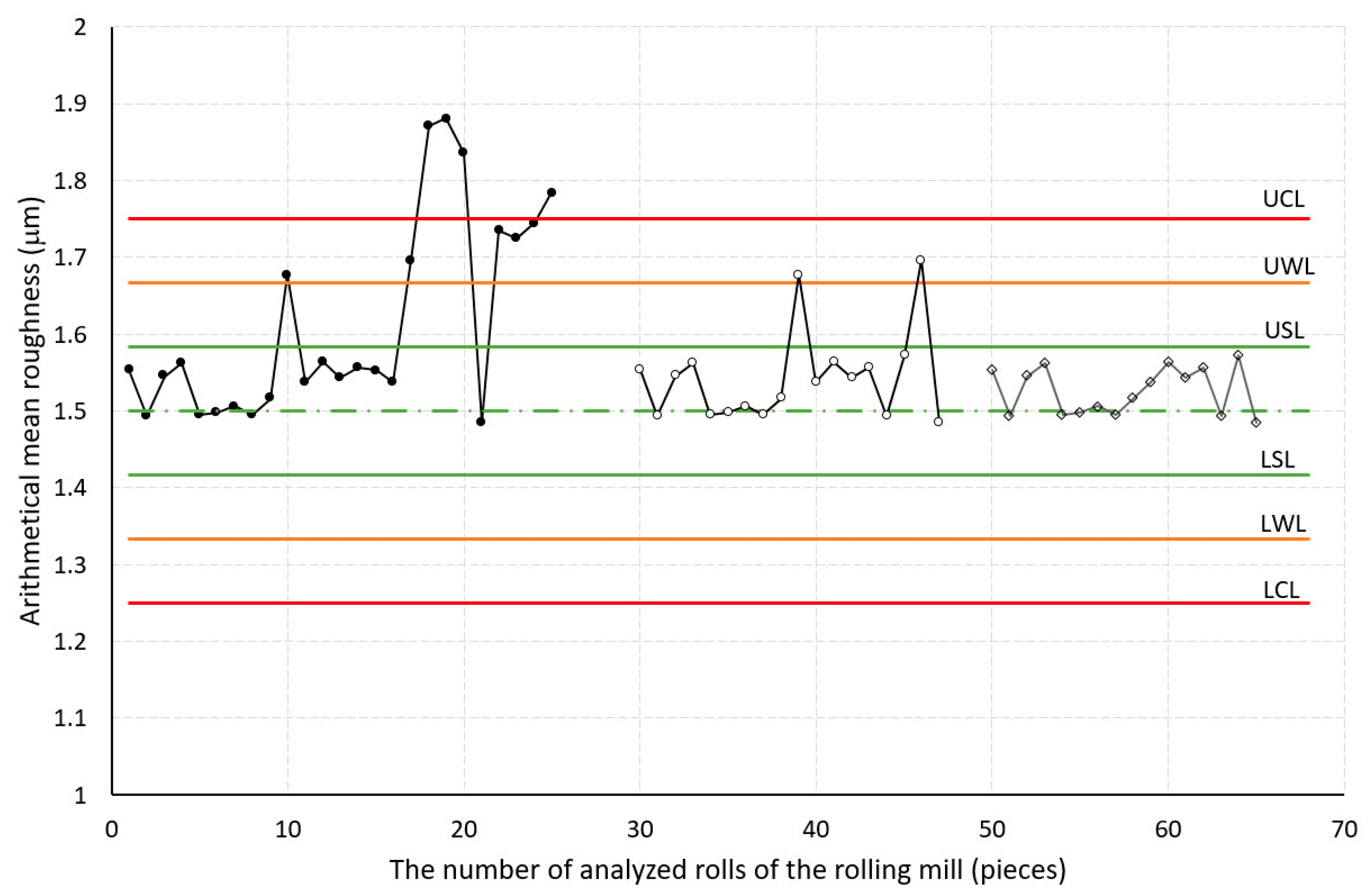
In the first step of the analysis phase, the following were indicated in the control diagram: CLRa,FR = TVRa,FR, UCLRa,FR, LCLRa,FR, UWRa,FR, LWLRa,FR, UCLRa,FR, and LCLRa,FR. Attention was focused first on identifying data that were out of the regulatory field CLRa,FR ± 0.25 μm; see Figure 3 (samples from 1 to 20, which are outside the regulatory boundaries, represent an unstable process). Data on these parts were excluded from further analysis because they are unstable processes. In the second phase, the Ra roughness data were analyzed; these were within the specified control limits (these are samples at x from 20 to 40 in Figure 3). It is assumed that the variability arose as a result of common (predictable) events, which the regulation of texturing process parameters can retain within the specified limits of UCLRa,FR and LCLRa,FR. If the statistical process is stabilized, i.e., definable causes are identified and analyzed, it is necessary to propose measures preventing their recurrence and, subsequently, propose measures for improvement. To assess the stability of the production process, it is possible to use the capability index Cpk, which is calculated according to Relations (10) and (11):
C P k , U = U C L X ¯ 3 . σ > 1.33 ,
C P k , L = X ¯ L C L 3 . σ > 1.33 ,
where Cpk,U is the process capability index calculated for the j-th texture quality sign UCLj;   X ¯ is the average value from the measured data of the j-th sign of texture quality; σ is the standard deviation of the measured data of the j-th sign of texture quality; and Cpk,L is the process capability index calculated for the j-th texture quality sign LCLj.
If the Cpk value is less than 1.0, the process is not capable. If the Cpk value is between 1.0 and 1.33, the process is considered barely capable, and if the Cpk value is greater than 1.33, the process is considered capable. If possible, it is necessary to aim for the highest possible Cpk value (greater than 2). If both the Cpk,U and Cpk,L values are greater than 1.33, the process is capable, and the process is under statistical control. In cases where one or both of the Cpk,U and Cpk,L values are smaller than 1.33, the process is not capable, and the process is not under statistical control.
Table 3 shows the Ra values measured in the zone between UCLRa and LCLRa (in the edge zone). From Table 3, it can be seen that the capability indexes Cpk,URa and CpkLRa for both the PE2 and PE3 experiment plans are greater than 1.33. This means that the PE2 and PE3 EDT processes are capable. For the EDT according to plan PE1, the value of CpkU = 1.13. This means that the process under this plan is not capable. However, measures need to be taken to improve it, as it is less than 1.33, and the projected number of non-compliant DPMOL,Ra products would be approximately 30,396 out of 1 million possibilities.
Table 4 shows the results after filtering out the data that were in the marginal area. The capability indexes’ values were greater than 1.33 in all three plans. This means that the processes in plans PE1, PE2, and PE3 are capable after filtering out data from the marginal area, and the predicted number of DPMORa of non-conforming products would be 1350 in the case of PE2, and ≈0 in the cases of PE1 and PE3. For illustration, a stepwise data filtering procedure is shown in Figure 3 for PE1. Data within the range 0–25 are from before the filtering out was performed (raw data), data within the range 30–45 are from after filtering out the data outside the UCL and LCL, and data in the range 50–65 are from after filtering out the data outside UWL-UCL and LWL-LCL.
In the case of Pc, only the lower limit value (LCLPc = 40 cm−1) is defined. Assuming that the lower control limit (LCLPc) is determined using Relation (12):
L C L P c = C L P c k . σ P C ,
Then, after adjusting Equation (12), we obtain Equation (13):
C L P c = L C L P c + k . σ P C ,
where k is a multiple of the standard deviation of the distance of the upper control limit from the center line (k = 3).
In our case, the maximum value of the directional deviation is equal to 7. This means that CL = 40 + 3 × 7 = 61 cm−1 (see Figure 4). It follows from this figure that the values of Pc determined from records PE1, PE2, and PE3 are higher than the lower LCLPc limit value. This means that the EDT processes PE1, PE2, and PE3 are capable of producing Pcs according to specifications without the need to take corrective action.
Control: Managing the process (object) by means of trial and error is ineffective. By purposefully controlling the process aimed at achieving a specified goal, it is possible to gradually set the input parameters using the purpose function [30]. The objective function of multicriteria optimization describing the relationships between input parameters Xi and output quality features SQj [22] was created by modifying the weighted product method (WPM) in the form of Equation (14):
S Q i = 1 n 1 n x 1 . w 1 + x 2 . w 2 + x n . w n ± Q j ,
where SQj represents the output quality feature; x1, x2, … xn represent the input independent factors of the process; wi represents the criterion weight; j represents a sign of quality; n represents the number of process input parameters; and ∆Qj represents the accuracy or uncertainty.
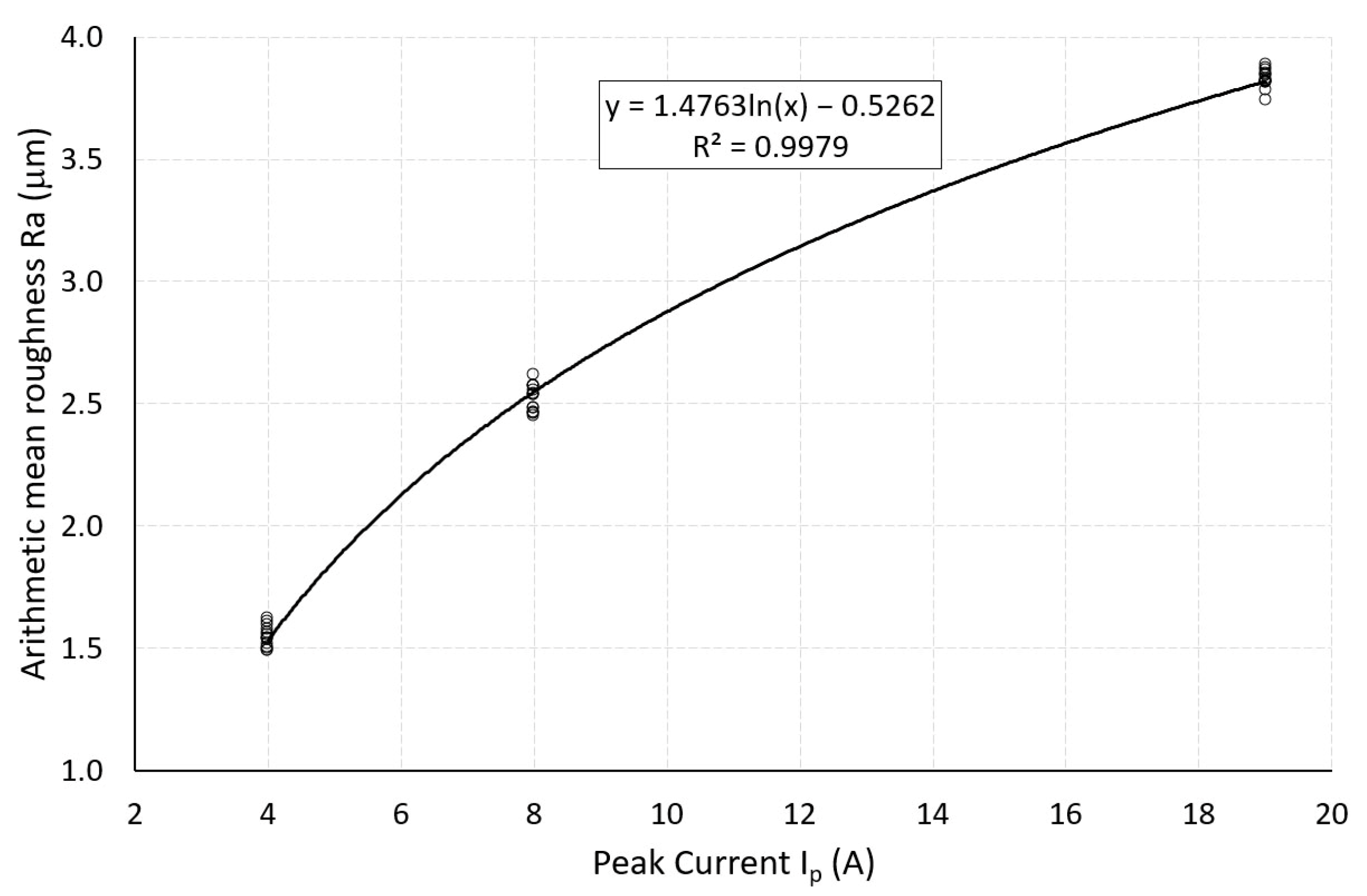
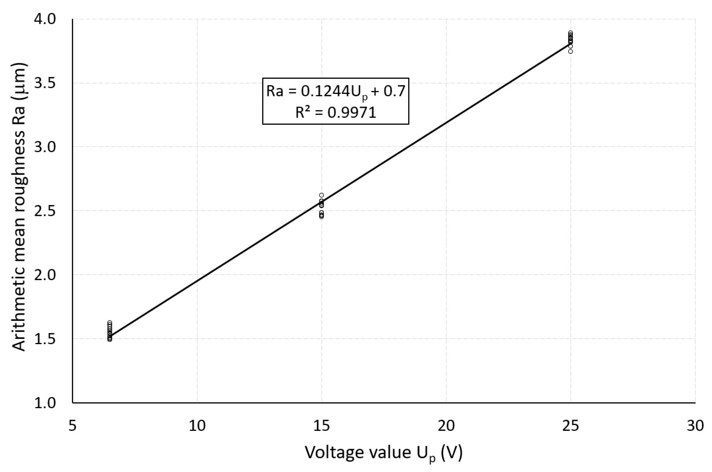
It can be seen from Figure 5, Figure 6, Figure 7 and Figure 8 that the dependences of Ra on the discharge energy, or the texturing process parameters Ip, Up, and Ton, show a good correlation, and the regression equations (Equations (15)–(17)) describe them with very high accuracy:
R a I p = 1.476 ln I p 0.5262 ;   R 2 = 0.99
R a U p = 0.1244 U p ;   R 2 = 0.99
R a T o n = 0.0915 T o n + 1.19 ;   R 2 = 0.99
One of the problems of multicriteria decision-making tasks is that individual criteria (characteristics of quality) or input parameters are expressed in different measurement units [22]. For this reason, it is convenient to transform them into a common unit so that they can be added. The method of relative parameters—planning assistance through technical evaluation of relevance number, PATTERN—is used in the technical, technological, and economic fields. This means that the change in the input parameters (Ip, Up, and Ton) and the quality sign Qj can be expressed as a ratio of the value of the Qj-th parameter to the value of the basic parameter Qj0 according to Relation (18):
I Q j i = Q j i Q j i 0 ,
where IQji is the degree of change in quality signs (Ra and Pc) according to the i-th process parameter; wi is the weight (significance) of the i-th process parameter; and n is the number of i-th process parameters.
If we substitute the individual indices of the change in quality Ra into Equation (14), we obtain
S Q R a = 1 n 1 3 I Q R a ( I p ) . w R a ( I p ) + I Q R a ( U p ) . w R a ( U p ) + I Q R a ( T o n ) . w R a ( T o n ) ,
After substituting into Equation (18), the change indices, depending on the input parameters of the texturing process, take the following form:
I Q R a ( I p ) = Q R a ( I p ) Q R a 0 ( I p ) = 4 = ( 1.4763 ln ( I p ) 0.0526 ) 1.4763 ln ( 4 0.0526 ) ,
I Q R a ( u p ) = Q R a ( U p ) Q R a ( U p ) = 6.5 = ( 0.1244 U p ) + 0.7 ) 0.1244 6.5 + 0.7 ) ,
I Q R a ( T o n ) = Q R a ( T o n ) Q R a 0 ( T o n ) = 6.5 = ( 0.0915 T o n + 1.1942 ) 0.0915 6.5 + 1.1942 ) ,
In the scalar multicriteria objective function, the approximation function (Figure 6, Figure 7 and Figure 8) with weight value wi is expressed in Equations (15)–(17) by coefficients for individual variables (wRa(Ip) = 1.476, wRa(Up) = 0.1244, wRa(Ton) = 0.0915) so that no influence of the considered process parameters is preferred. After substituting Equations (20)–(22) into Equation (19), we obtain the overall effect of the texturing process parameters on the Ra quality sign:
S Q R a = 1 3 ln I I , R a + I U , R a + I T o n , R a ± Q R a ,
Figure 9 shows the dependence between the total value of the quality feature SQRa and the calculated roughness values YQRa according to Relation (23), which is described by regression Equation (24):
Y Q R a = 1.526 S Q R a + 0.0091 ± Q R a ,
After modifying Model (23) into a simpler form, we obtain
Y Q R a = 0.494 ln I p + 0.0424 U p + 0.0298 T o n + 0.437 ± Q R a ,
Model (25) was subsequently tested for target roughness values TVRa1 = 1.5 μm, TVRa2 = 2.5 μm, and TVRa3 = 3.8 μm. The presented model allows one to predict the roughness YQRra based on the pulse current Ip, the gap voltage Up and the pulse on-time Ton. Table 5 compares the calculated YQRa values from Model (25) with the target values TVRa1 = 1.5 μm, TVRa2 = 2.5 μm, and TVRa2 = 3.8 μm.
The comparison shows that there was good agreement between the calculated values according to Model (25) and the target values: for target value TVRa1 = 1.5 μm, ΔRa = 0.014 μm and capability index CpkRa1 = 1.311; for target value TVRa2 = 2.5 μm, ΔRa = 0.011 μm and capability index CpkRa2 = 1.325; and for target value TVRa3 = 3.8 μm, ΔRa = 0.006 μm and capability index CpkRa3 = 1.355. This means that the texturing process for plans PE1 and PE2 is ineligible because the capability index is Cpk < 1.33. When Ton was changed by 1 μs, the CpkRa capability indices were assumed to be greater than 1.33 when PE 1, PE2, and PE 3 plans were applied. This implies that texturing with these plans should be eligible. Reducing the Six Sigma level by one level, from four to five, will reduce the cost of poor quality by 10%. Thus, it is necessary to change the process parameters to achieve a change in the standard deviation from 0.06 to 0.048.
The proposed model was also tested using the parameters presented in [28], as they are closely related to the results in this paper. Since the authors of [28] only investigated the effect of pulse current Ip and pulse on-time Ton, Model (23) was modified as follows:
Y Q R a = 0.745 ln I p + 0.045 T o n + 0.331 ± Q R a ,
The difference is that the authors of [28] tested their prediction model for the target roughness value TVRa = 3 μm only for the input texturing parameters Ip = 20 A and Ton = 12 μs. In this case, the capability index CpkRa was 0.818. When Ton was changed by 2 μs and Ip by 1 A, the capability index was 1.373.
The deviation (inaccuracy) ∆Ra was calculated from the difference between the calculated YQRa values and the specified target values CLRa,FR = TVRa,FR:
R a = Y Q R a C L R a , F R ,
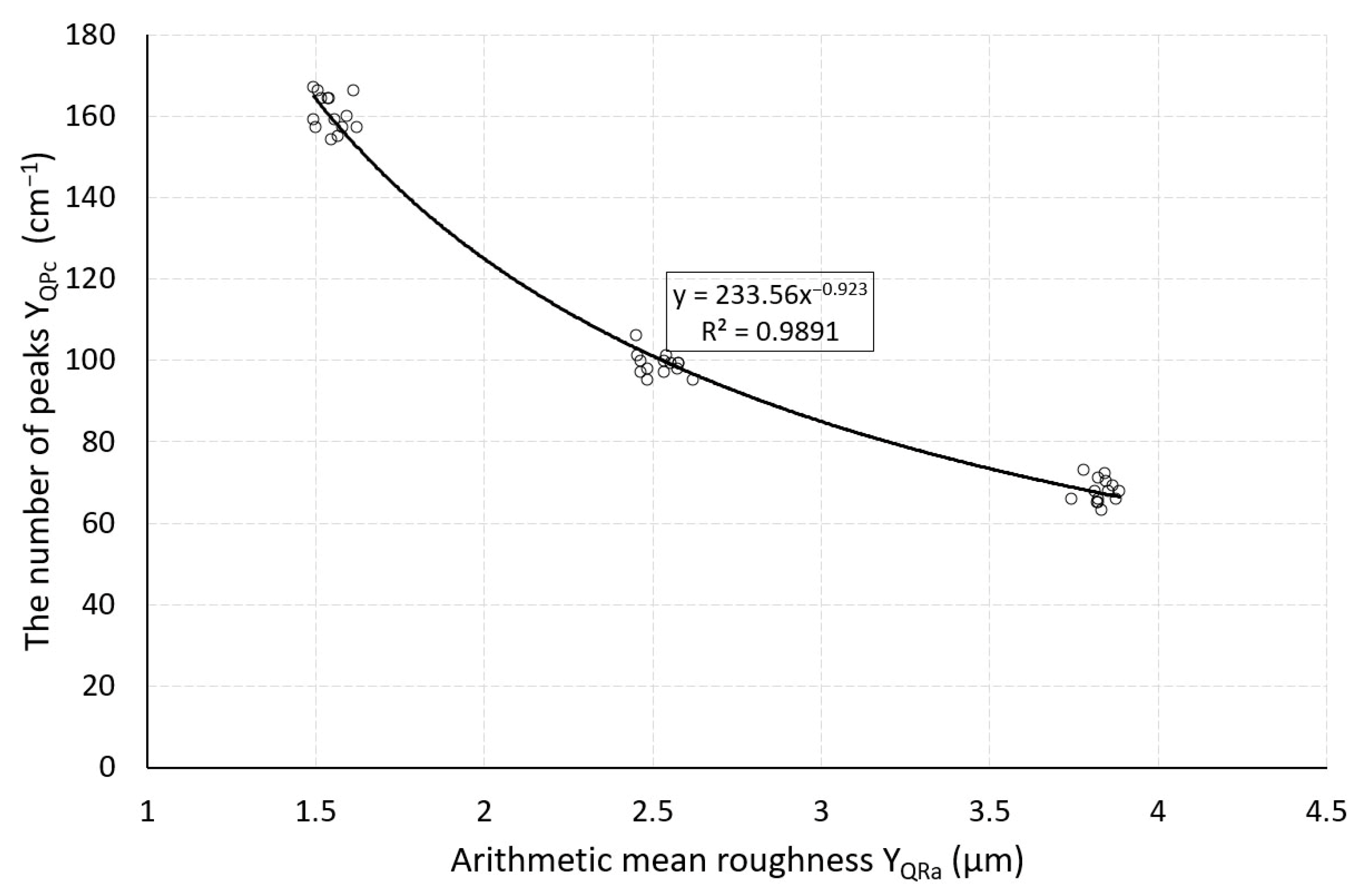
In the analyzed interval of texturing parameters Ip, Up, and Ton, the values of ∆R were ±0.015 μm. Similar to [4,28], the assumption was confirmed in our case that a very good correlation (R2 = 0.989) was recorded between the roughness Ra and the peak density Pc at the output of the EDT rolls (see Figure 9 and Figure 10). This dependence was described by the regression equation, Equation (28):
Y Q P c = 233.6 Y Q R a 0.923 ,
P c = Y Q P c C L P c ,
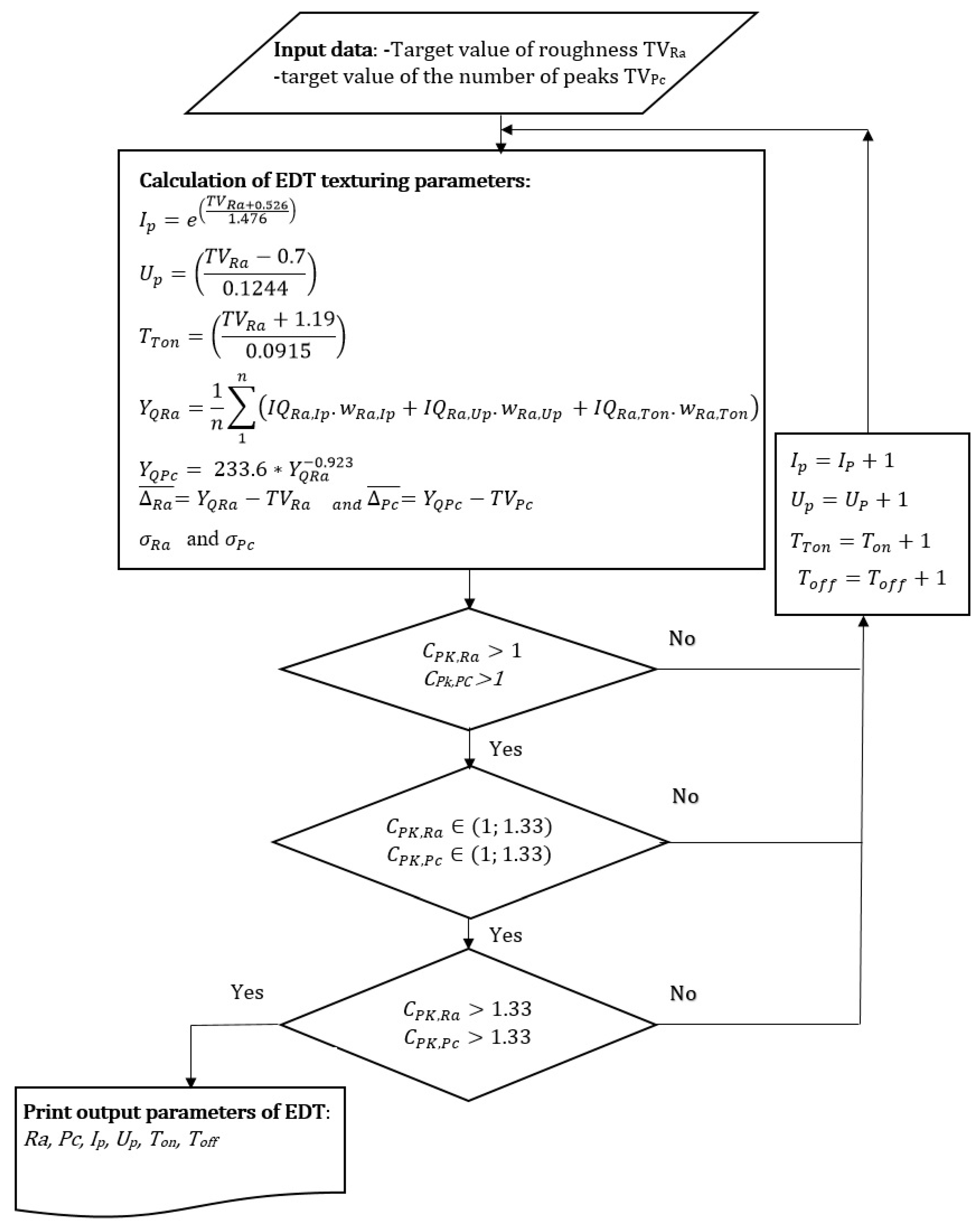
The decision process (process control) of texturing was described by the following algorithm (see Figure 11):
The sequence of steps followed in this algorithm is as follows:
  • 1. Step: defining the target values of quality characteristics TVRa and TVPc.
  • 2. Step: Assignment of input parameters of the EDT process (Ip, Up, Ton, and Toff) to defined target values TVRa and TVPc according to Formulas (30)–(33):
P c I p = 322.24   I P 0.539 ;   R 2 = 0.97
P c U p = 512.74 U p 0.621 ;   R 2 = 0.98
P c T o n = 287.87 T o n 0.421 ,   R 2 = 0.98
P c T o f f = 357.33 T o f f 0.459 ,   R 2 = 0.99
  • 3. Step: Calculation of the values of qualitative characteristics YQRa and YQPc according to Formulas (25) and (28), calculation of ∆Ra and ∆Pc according to Formulas (27) and (29), and calculation of indices CpkL and CpkU according to Formulas (10) and (11). Thus, for Cpk ≥ 1.33, the standard deviation after adjustment of the equations is
σ = U C L R a ¯ 3 1.33 = 0.25 0 3 1.33 = 0.06
  • 4. Step: Comparison of calculated values of CpkRa and CpkPC with the limit value 1. If the calculated values of CpkRa and CpkPc are less than 1, the process is not capable, and it is necessary to adjust the input parameters.
  • 5. Step: If the calculated values of CpkRa and CpkPC are in the interval from 1 to 1.33, the process is capable, but the compliance rate is low, so it is recommended to take measures to improve the stability of the process.
  • 6. Step: If the calculated CpkRa and CpkPC values are greater than 1.33, the compliance rate is high, and no process improvement measures need to be taken.
  • 7. Step: Printing of output parameters of the quality characteristics Ra, Pc, and the input parameters of the EDT process Ip, Up, Ton, and Toff.

4. Conclusions

Based on the results of the analyses, the following conclusions were formulated:
  • On the basis of control diagrams, Cpk capability indices, and Z scores, it is possible to take measures to improve the quality characteristics Ra and Pc of the surface textures of the rolls in rolling mills.
  • The results obtained by means of regression analysis indicate that the roughness Ra created during EDT is strongly dependent on the discharge energy. The coefficient of determination R2 reached values greater than 0.99.
  • The parameters Ip, Up, and Ton of the EDT process have a major influence on the roughness Ra. An increase in these parameters of the texturing process leads to an increase in Ra values.
  • Using regression analysis, the dependences of Ra on Ip were described by a logarithmic regression equation, and the dependences of Ra on both Up and Ton were described by linear regression equations. The regression models showed a strong correlation (R2 > 0.9).
  • Using the obtained dependencies, a purpose function was created and verified. This function allows one to predict the roughness Ra with an accuracy of ± 0.02 μm in the analyzed interval of texturing parameters Ip, Up, and Ton.
  • The regression equation of the dependence of the peak density Pc on Toff was used to predict the peak density. The R2 coefficient was greater than 0.98.
  • Based on the comparison of the conformity of the Cpk capability indices with the limit values, an algorithm was designed, which allows step-by-step decisions to be made to improve the EDT process of rolling mill rolls.
The design of a procedure for taking corrective actions to improve the roughness Ra of EDT rolls based on the CpkRa capability index also allows the prediction of the amount of non-conforming products out of one million DPMO cases compared to other procedures. Thus, by controlling the texturing process on the cold mill work roll surface based on the proposed algorithm, the number of non-conforming products can be minimized. Future efforts will be focused on verification of the roughness Ra of work rolls ranging from 1.1 μm to 1.6 μm, as presented in a previous work [31]. Furthermore, future studies will also verify whether both the required values of TVRa and TVPc are achieved on the surface of the sheet metal.

Author Contributions

Conceptualization, E.E. and V.K.; methodology, E.E.; formal analysis, E.E. and V.K.; investigation, E.E.; resources, E.E. and V.K.; data curation, V.K.; writing—original draft preparation, E.E. and M.T.; writing—review and editing, E.E. and M.T.; visualization, E.E.; supervision, E.E.; project administration, E.E.; funding acquisition, E.E. All authors have read and agreed to the published version of the manuscript.

Funding

This research and the APC were funded by Vedecká grantová agentúra MŠVVaM SR a SAV, grant number VEGA 1-0238-23.

Data Availability Statement

Data are available on request due to restrictions of the funder.

Acknowledgments

The work was accomplished under project VEGA 1-0238-23 “Implementation of CAx systems and virtual engineering techniques in the redesign of car-body parts for deformation zones”.

Conflicts of Interest

Author Vladimír Kokarda was employed by Carl Zeiss Slovakia. The remaining authors declare that the research was conducted in the absence of any commercial or financial relationships that could be construed as a potential conflict of interest.

References

  1. Sakuramoto, C. Automotive Skin Panels Quality Improvement by Means of Finite Element Method. In Proceedings of the Conference SAE Commercial Vehicle Engineering Congress (COMVEC), Rosemont, IL, USA, 1–3 October 2013. [Google Scholar] [CrossRef]
  2. Schulte, C.; Li, X.; Abel, D.; Hirt, G. Model-based Control of the Strip Roughness in Cold Rolling. FAC Pap. 2021, 54, 109–114. [Google Scholar] [CrossRef]
  3. Çolak, B.; Zahoor, A.; Özakin, B.; Kurgan, N. An Experimental Investigation into Roughness Transfer in Asymmetrical Rolling of Steel Strips. Karadeniz Fen Bilim. Derg. 2023, 13, 1070–1089. [Google Scholar] [CrossRef]
  4. Çolak, B.; Kurgan, N. An experimental investigation into roughness transfer in skin-pass rolling of steel strips. Int. J. Adv. Manuf. Technol. 2018, 96, 3321–3330. [Google Scholar] [CrossRef]
  5. Cavallari, M.; Gaboardi, P.; McWhirter, R.; Perassolo, M.; Trevisan, C. New Surface Finishes for Cold Rolling Mills. In Proceedings of the METEC & 2nd ESTAD 2015, European Steel Technology and Application Days, Düsseldorf, Germany, 15–19 June 2015. [Google Scholar]
  6. Elkoca, O. A study on the characteristics of electrical discharge textured skin pass mill work roll. Surf. Coat. Technol. 2008, 202, 2765–2774. [Google Scholar] [CrossRef]
  7. Rodriguez-Vidal, E.; Matthews, D.T.A.; de Viteri, V.S.; Korver, F.; Wentink, D.J.; Quintana, I. Surface design and texturing of strip steel using nanosecond pulsed lasers for simulated roughness transfer and paint appearance. J. Mater. Process. Technol. 2020, 275, 116365. [Google Scholar] [CrossRef]
  8. Evin, E.; Tomáš, M.; Kmec, J. Optimization of Electro-Discharge Texturing Parameters for Steel Sheets’ Finishing Rollers. Materials 2020, 13, 1223. [Google Scholar] [CrossRef]
  9. Bartkowiak, T.; Mendak, M.; Mrozek, K.; Wieczorowski, M. Analysis of Surface Microgeometry Created by Electric Discharge Machining. Materials 2020, 13, 3830. [Google Scholar] [CrossRef] [PubMed]
  10. Nieslony, P.; Wojciechowski, S.; Gupta, M.K.; Chudy, R.; Krolczyk, J.B.; Maruda, R.; Krolczyk, G.M. Relationship between energy consumption and surface integrity aspects in electrical discharge machining of hot work die steel. Sustain. Mater. Technol. 2023, 36, e00623. [Google Scholar] [CrossRef]
  11. Hourmand, M.; Farahany, S.; Sarhan, A.A.D.; Noordin, M.Y. Investigating the electrical discharge machining (EDM) parameter effects on Al-mg 2 Si metal matrix composite (MMC) for high material removal rate (MRR) and less EWR–RSM approach. Int. J. Adv. Manuf. Technol. 2015, 77, 831–838. [Google Scholar] [CrossRef]
  12. Straka, Ľ.; Piteľ, J.; Čorný, I. Influence of the main technological parameters and material properties of the workpiece on the geometrical accuracy of the machined surface at wedm. Int. J. Adv. Manuf. Technol. 2021, 115, 3065–3087. [Google Scholar] [CrossRef]
  13. Bidulska, J.; Kvackaj, T.; Bodak, V.; Bidulsky, R. The Microgeometry Parameters of Uncoated and Zinc-Coated Cold Rolled Steel Strips. J. Met. Mater. Miner. 2007, 17, 1–7. [Google Scholar]
  14. Çolak, B.; Kurgan, N. EDT ve Sbt Yöntemleriyle Pürüzlendirilmiş Soğuk Hadde Merdanelerinin Yüzey Pürüzlülük Etkilerinin Karşılaştırılmasına Dair Bir Çalışma. In Proceedings of the 1st International Iron and Steel Symposium (IISS′12), Karabuk, Turkey, 2–4 April 2012; Karabuk University: Karabuk, Turkey, 2012; p. 861. [Google Scholar]
  15. Gorbunov, A.V.; Belov, V.K.; Begletsov, D.O. Texturing of Rollers for the Production of Auto-Industry Sheet. Steel Transl. 2009, 39, 696–699. [Google Scholar] [CrossRef]
  16. Simao, J.D.; Aspinwall, K.; Wise, M.L.H.; El-Menshawy, M.F. Electrical discharge texturing of cold mill work rolls using different tool electrode materials. Iron Steel Eng. 1996, 73, 42–47. [Google Scholar]
  17. Colak, B.; Basoglu, F.; Kurgan, N. Texturing methods for cold mill work rolls. In Proceedings of the Fourth International Iron and Steel Symposium, Karabuk, Turkey, 4–6 April 2019; pp. 424–431. [Google Scholar]
  18. Świercz, R.; Holubek, R. Experimental investigation of influence electrical discharge energy on the surface layer properties after EDM. Weld. Technol. Rev. 2020, 92, 7–13. [Google Scholar] [CrossRef]
  19. Munro, R.A.; Ramu, G.; Zrymiak, D.J. The Certified Six Sigma Green Belt Handbook, 2nd ed.; Quality Press: Welshpool, Australia, 2015. [Google Scholar]
  20. Giampieri, A. A review of the current automotive manufacturing practice from an energy perspective. Appl. Energy 2020, 261, 114074. [Google Scholar] [CrossRef]
  21. Coleman, S. Six Sigma: An opportunity for statistics and for statisticians. Significance 2008, 5, 94–96. [Google Scholar] [CrossRef]
  22. Tyzdek, T.; Keller, P.A. The Six Sigma Handbook, 3rd ed.; The McGraw-Hill Companies: New York, NY, USA, 2010. [Google Scholar]
  23. Schindlerova, V.; Marcik, J.; Čada, R.; Sajdlerova, I. Analysis of Non-Conforming Production in an Engineering Company. Tech. Gaz. 2024, 31, 296–302. [Google Scholar] [CrossRef]
  24. Mittal, A.; Gupta, P.; Kumar, V.; Ali Al Owad, A.; Mahlawat, S.; Sumanjeet Singh, S. The performance improvement analysis using Six Sigma DMAIC methodology: A case study on Indian manufacturing company. Heliyon 2023, 9, e14625. [Google Scholar] [CrossRef]
  25. Gijoa, E.V.; Scaria, J.; Antony, J. Application of Six Sigma Methodology to Reduce Defects of a Grinding Process. Qual. Reliab. Eng. Int. 2011, 27, 1221–1234. [Google Scholar] [CrossRef]
  26. Ganguly, K. Improvement process for rolling mill through the DMAIC six sigma approach. Int. J. Qual. Res. 2012, 6, 221–231. [Google Scholar]
  27. Laddha, S.A.; Desai, G. Quality improvement in building construction using six sigma. Int. Res. J. Eng. Technol. 2019, 6, 7711–7713. [Google Scholar]
  28. Terpák, L.; Dorčák, J.; Revaj, J. Quality Control of the Electro-Discharge Texturing. Metalurgija 2010, 49, 19–22. [Google Scholar]
  29. DIN EN ISO 4288; Geometrical Product Specifications (GPS)—Surface Texture: Profile Method—Rules and Procedures for the Assessment of Surface Texture. International Organization for Standardization (ISO): Geneva, Switzerland, 2009.
  30. Červeňanská, Z.; Važan, P.; Juhás, M.; Juhásová, B. Multi-Criteria Optimization in Operations Scheduling Applying Selected Priority Rules. Appl. Sci. 2021, 11, 2783. [Google Scholar] [CrossRef]
  31. Kundracik, V. Strip surface microgeometry for automotive surface car-body parts. Galvanized material for automotive industry. In Proceedings of the 66th Workshop of the STEEL STRIP Company, Košice-Jahodná, Slovakia, 12–14 October 2009; pp. 28–33. (In Slovak). [Google Scholar]
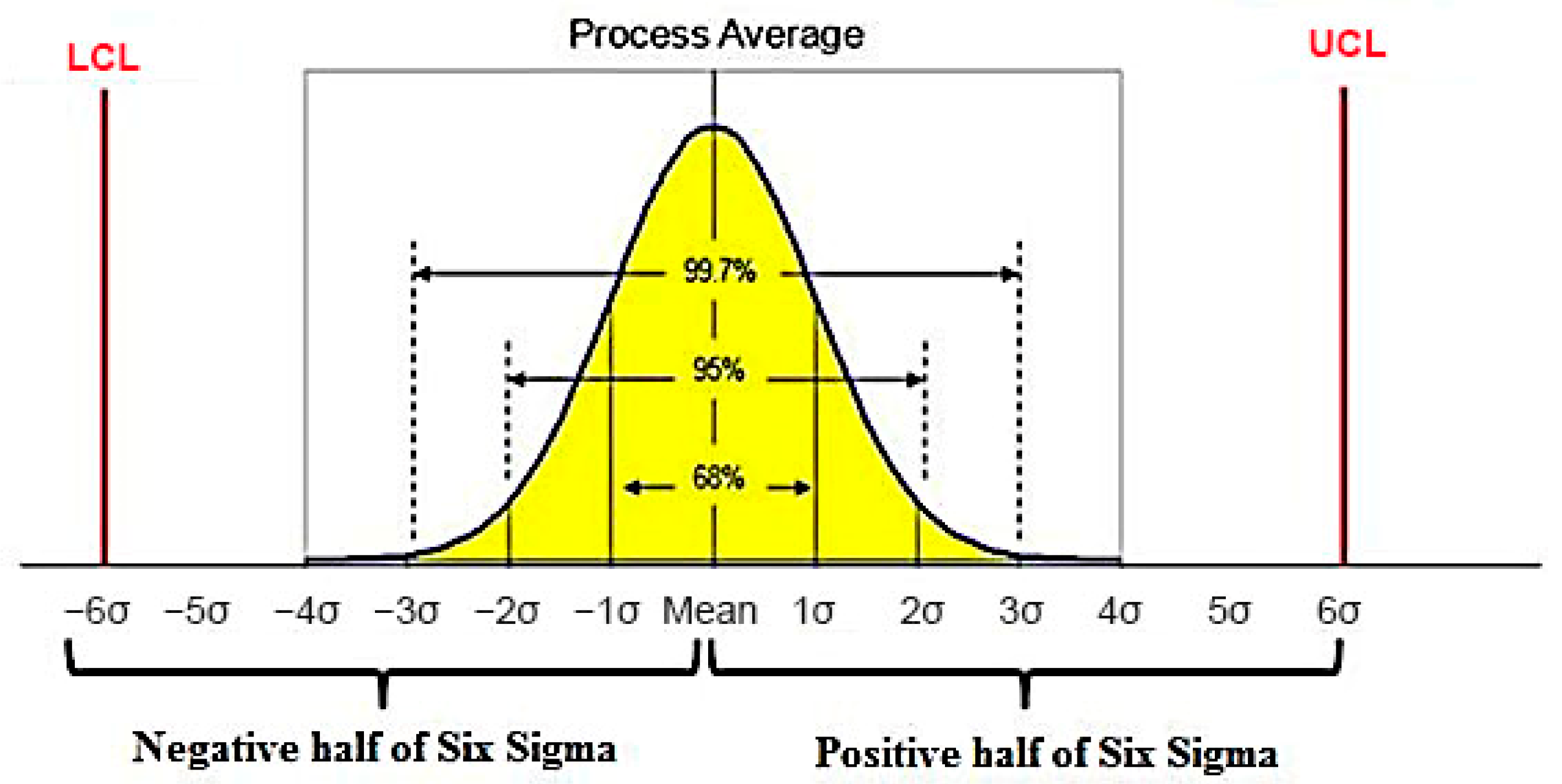
Figure 1. Probability of occurrence of non-conforming products.
Processes 13 00450 g001
Figure 2. Representation of measuring points on the work rolls.
Processes 13 00450 g002
Figure 3. Detection of a gradual change in roughness Ra—PE1.
Processes 13 00450 g003
Figure 4. Detection of a gradual change in the peak density Pc—PE1.
Processes 13 00450 g004
Figure 5. Dependence of roughness Ra on discharge energy DEp.
Processes 13 00450 g005
Figure 6. Dependence of roughness Ra on discharge current Ip.
Processes 13 00450 g006
Figure 7. Dependence of roughness Ra on discharge voltage Up.
Processes 13 00450 g007
Figure 8. Dependence of roughness Ra on pulse on-time Ton.
Processes 13 00450 g008
Figure 9. Dependence of roughness YQRa on SQRa.
Processes 13 00450 g009
Figure 10. Dependence the number of peaks Pc on mean roughness YQRa.
Processes 13 00450 g010
Figure 11. Process control of EDT.
Processes 13 00450 g011
Table 1. Six Sigma conversion table.
Capability Index Cpk min11.131.331.491.6671.751.832
Six Sigma level (Zmin score)33.3944.555.255.56
DPMO660,80730,3966210135023388323
Cost of poor quality COPQ25% to 45%15% to 25%5% to 15%
Table 2. Plan of experiments—input values.
PE 1
TRa1 = 1.5
(μm)
PE 2
TRa2 = 2.5
(μm)
PE 3
TRa3 = 3.8
(μm)
Texture current Ip (A) 41819
Lower voltage limit UPL (V)51015
Upper voltage limit UPH (V)82025
Pulse duration Ton (μs)41429
Technological break duration Toff (μs)61638
Electrode diameter d (mm)888
Note: PE 1—plan of experiment 1; PE 2—plan of experiment 2; PE 3—plan of experiment 3; TRa,1—target value in PE 1; TRa,2—target value in PE 2; TRa,3—target value in PE 3.
Table 3. Measured values in the variation range VRRa = CLRa,RR ± VRRa,SS—first step.
Measure ValuePE 1 PE 2 PE 3
Ra (μm)Pc (cm−1)Ra (μm)Pc (cm−1)Ra (μm)Pc (cm−1)
Average value R a ¯ 1.5481612.5993.84568
Standard deviation SD0.0670.0630.043
Upper-level Six Sigma ZU3.38-4.49-2.25-
Lower-level Six Sigma ZL4.9818.64.4821.17.5310.0
CpKU1.13-1.50-1.75-
CpKL1.666.21.497.052.51-
DPMO30,396013500883.36
Table 4. Measured values in the variation range VRRa = CLRa,RR/3 ± VRRa,SS—second step.
Measure ValuePE 1 PE 2 PE 3
Ra (μm)Pc (cm−1)Ra (μm)Pc (cm−1)Ra (μm)Pc (cm−1)
Average value R a ¯ 1.5261582.495993.8368
Standard deviation SD0.0370.0530.023
Upper-level Six Sigma ZU7.19-4.73-10.0-
Lower-level Six Sigma ZL8.8818.14.5621.112.919.59
CpKU2.40-1.58-3.34-
CpKL2.966.01.527.054.313.20
DPMO001350000
Table 5. Results of prediction Model (25) and its testing using data from ref. [28].
Input DataCalculated Data

Plan
IP
(A)
UP
(V)
Ton
(μs)
TVRa
(μm)
YQRa
(μm)
ΔRa
(μm)
S.D.Ra
(μm)
Cpk
(μm)
DPMO (Pieces)
PE 146.541.51.5140.014 1.311≈6200
PE 2815142.52.5110.0110.061.325≈6200
PE 31925293.83.8060.006 1.355≈4300
After improvement Ton-1
PE 146.531.51.484−0.016 1477≈4300
PE 2815132.52.482−0.0180.061491≈4300
PE 31925283.83.776−0.024 1522≈4300
Verification of Model (25) acc. to input parameters of [28]
[28]20-123.03.1030.1030.060.818≈190,000
After improvement Ton-2 and Ip-1
[28]19-103.02.979−0.0030.061.373≈4300
Disclaimer/Publisher’s Note: The statements, opinions and data contained in all publications are solely those of the individual author(s) and contributor(s) and not of MDPI and/or the editor(s). MDPI and/or the editor(s) disclaim responsibility for any injury to people or property resulting from any ideas, methods, instructions or products referred to in the content.