Abstract
With the rapid growth in coal demands driven by economic development, the applications scenarios of long-distance, high-power mining operations in underground coal mines has gradually been expanded. Taking voltage regulation technology for long-distance power supply in underground coal mines as the research object, this paper analyzed the mechanisms behind voltage fluctuation hazards and the status quo of existing voltage regulation technologies in coal mines and put forward a voltage regulation technology for long-distance power supply in tunneling faces of coal mines based on on-load voltage regulation. On this basis, a voltage regulation device for long-distance power supply in underground coal mines was designed and applied to the long-distance power supply system of Wanli Coal Mine’s tunneling faces. All indicators met the design requirements, validating the effectiveness of the device and the applicability of the research outcomes, and providing an effective solution for addressing voltage fluctuations in the long-distance power supply of underground coal mines.
1. Introduction
Coal is a fundamental energy source for China, and its dominant position in energy consumption is expected to remain unchallenged for the foreseeable future [1,2,3]. With the development and progress of modern coal mining technology, the level of modernization and intelligence in underground mining production continues to improve, and coal mines with an annual capacity of ten million tons are being progressively implemented. With the rapid growth in energy demand, the efficient and collaborative operation of coal mine comprehensive tunneling equipment has become a key approach to improving coal mining efficiency [4]. The proportion of high-power electrical equipment has also continued to rise. The power of coal mining units has reached 5000 kW, with individual coal mining machines exceeding 3000 kW. The power of roadheader units has been raised to over 2000 kW. Additionally, some impulsive and non-linear loads are being introduced into these systems. which have in turn caused a series of power quality issues in underground power networks. Among these are reduced power factor, voltage fluctuations, and voltage and current waveform distortions. The primary source of voltage fluctuations in mines is the impulsive loads generated by large equipment. The starting and stopping, loading and unloading of large motors—such as the startup of roadheaders and the startup and coal-cutting—produce significant impulsive loads. High-voltage cables are key equipment for high-voltage, large-capacity, long-distance power transmission [5]. In China’s coal mine power supply systems, power cables are the primary power transmission lines, making up over 90% of the power transmission lines [6,7]. With the widespread adoption of rapid mining technology, the supply distance between relevant equipment and their source substations in the mining face of underground coal mines has gradually increased—from under 1000 m to 3000–5000 m. In such long power supply distances, together with the harsh underground working environment, the voltage drops in lines and cables caused by both reactive and active currents during the operation of motors causes critically low supply voltage at the load end of the power supply cables, substantial load variations associated with equipment start-up and shutdown, and pronounced voltage fluctuations within the supply circuit. The coal mine power supply system generally requires not only reliability, safety, and cost-effectiveness, but also excellent power quality and sufficient power supply capacity [8]. If the above power quality issues in underground coal mines are not monitored and addressed, they will probably lead to difficulties in motor startup, frequent motor burnouts, deterioration of cable insulation, threats to the reliability of the coal mine power supply, and the safety of production. If voltage fluctuations are not monitored and addressed in time, they can result in several serious consequences:
- (1)
- Impact on terminal equipment motors
Excessive fluctuations in power supply voltage can affect the magnetic flux in the iron core, torque, rotational speed, output power, stator current, reactive power absorption, efficiency, and heating of the motor, result in unstable motor speed, poor load-carrying capability, and difficulties in motor startup. In severe cases, motors may burn out. Furthermore, fluctuations in power grid voltage can severely damage inverters. Minor voltage fluctuations may cause a fuse to blow quickly, while severe ones could destroy the entire inverter unit [9,10]. Below, a qualitative analysis will be made on the impact of fluctuations in power supply voltage on the motor. At a constant frequency, the level of power supply voltage directly affects the motor startup performance. Excessively low voltage weakens the rotating magnetic field generated by the stator windings, causing insufficient startup torque, prolonged startup time, and difficulty in motor startup. This is because the starting torque, running torque, and maximum torque of a motor are all proportional to the square of the voltage. When the voltage drops to a certain level, the motor can stop, and in extreme cases, it could reverse, leading to safety hazards.
- (2)
- Impact on the insulation of power cables
With the advancement in intelligent construction within coal mines and the increasing complexity of underground power grid equipment, voltage fluctuations overlap and intensify harmonic issues [11,12]. High-voltage operations accelerate the aging of the insulation of power supply and use equipment, significantly shorting the lifespan of cables and equipment [13]. The main impact mechanism is to cause the insulation to deteriorate, which, in severe cases, can drastically shorten the lifespan of conventional cables and even cause accidents [14,15,16]. In a three-phase three-wire system, each phase’s voltage and current should maintain the same frequency and amplitude while having a 120-degree phase difference—referred to as three-phase symmetry. However, when cable insulation deteriorates to a certain extent, the cable’s distributed capacitance increases, and the insulation resistance decreases, causing asymmetry in the three-phase insulation parameters and uneven working voltages across the system. Long-term exposure to such asymmetry not only shortens the lifespan of other electrical equipment, but also reduces the normal service life of cables, further contributing to the deterioration of the insulation of corresponding cables and forming a vicious circle [17]. Insulation deterioration can lead to a partial discharge. If the number of local discharges continues to grow, it may lead to a decline in the insulation level of the cable, potentially leading to malfunctioning cables or leakage faults. If not handled properly, leakage faults can escalate into grounding or short-circuit problems, causing override trip and widespread power outages [18,19].
- (3)
- Impact on safety production in coal mines
In China’s underground coal mining sector, high-gas mines account for the vast majority. Most of the loads in these mines are classified as Class I. A sudden power outage can lead to the accumulation of toxic and flammable substances like CH4, CO2, CO, and coal dust due to limited ventilation conditions under the shaft. Such situations are extremely dangerous and require stringent preventive measures to avoid similar incidents [20]. If cables or equipment experience leakage or arcing, an electric spark that reaches the minimum ignition energy for gas or coal dust (0.28 mJ) can ignite these substances, posing a significant threat to safety during coal mining operations and endangering workers’ lives [21,22,23]. According to incomplete statistics from accident surveys in China, electrical sparks account for 40% to 47% of gas explosion accidents in underground coal mines. During 7 years from the end of 2007 to 2014, more than ten accidents were caused by cable issues occurred in coal mining, resulting in more than a hundred casualties [24]. Low temperatures, humidity, dust, noise, toxic and hazardous gases, heavy electrical loads and long power supply distances, etc. are key factors contributing to these incidents [25,26]. In central and eastern regions where the air humidity in underground coal mines is generally above 90%, there is frequent dripping and waterlogging, poor heat dissipation in chambers and tunnels, and high temperatures [27,28]. The harsh conditions faced by cables and other electrical equipment, combined with voltage fluctuations from long-distance power supply accelerate insulation aging and increase the likelihood of failures. Thus, improving the quality of long-distance power supply is also a necessary condition for the safe and reliable operation of coal mines [29]. From the perspectives of power supply reliability and production safety in coal mines, it is necessary to study the technology and equipment to reduce fluctuations in power grid voltage and improve the safety of underground coal mine power supply systems [30].
With the continuous increase in equipment power and supply distance at tunneling faces, the voltage loss induced by long-distance power supply has become increasingly serious, leading to voltage drop at the end of the line, difficulties in motor startup, under-voltage operation, reduced actual power factor, and even power supply accidents, thus seriously affecting the safe production of coal mines. The existing solutions are either to increase the output voltage of mobile transformers or to add a mobile transformer to the middle of the line for secondary voltage step-up. However, both methods expose cables and electrical equipment to prolonged high-voltage hazards, increase energy loss, while shortening their service life. Additionally, according to Coal Mine Safety Rules, mobile transformers added to the middle of the line must be placed in tunnel chambers, thus complicating the design and increasing investment costs. Consequently, there is an urgent need to develop solutions that can achieve real-time on-load voltage regulation based on variations in equipment power.
2. Current Research on On-Load Automatic Voltage Regulation Technology
Currently, common methods for reducing the impact of voltage fluctuations in ground power supply systems include generator-side voltage regulation at power plants, reactive power compensation devices, adjustment of power system network parameters, and transformer voltage regulation [31]. Generator-side voltage regulation at power plants adjusts the output voltage by modifying the excitation of the generator to meet the voltage demand of short-distance load or direct load. However, it is not suitable for coal mine power supply systems with large-scale power supply and multi-stage transformers [32].
Electric grid voltage regulation technology can be divided into no-load voltage regulation and on-load voltage regulation based on the regulation methods. No-load voltage regulation requires interrupting the circuit power supply to adjust the voltage. It is mostly used in seasonally shut-down substations, where it is impossible to perform on-load voltage regulation in response to load fluctuations. Therefore, distribution networks have increasingly adopted on-load voltage regulation, which can dynamically adjust voltage based on load variations. Table 1 shows a comparison of transformer on-load and no-load voltage regulation technologies. It is evident that no-load voltage regulation technology is unsuitable for voltage regulation in long-distance power supply scenarios in underground coal mines.

Table 1.
Comparison of Transformer On-load and No-load Voltage Regulation Technologies.
Currently, common on-load voltage regulation methods used in coal mines include mobile transformer voltage regulation and reactive power compensation voltage regulation. Voltage regulation on mobile transformers is the most direct method, primarily achieved through on-load tap changers. More than 90% of transformers are equipped with tap changers. Thus, as an execution mechanism, on-load tap changers were historically a research focus in on-load voltage regulation technology [33,34]. At present, research on automatic on-load tap-changing voltage regulation technology mainly centers around improving the control of power electronic switching devices and auxiliary switching components [35,36,37,38,39,40,41,42,43]. For example, Refs. [44,45] introduced PI control and fuzzy logic control into the control of a tap changer, which increased the accuracy of the automatic voltage regulation process. Mobile transformer direct voltage regulation involves modifying a mine-duty mobile transformer to directly increase the voltage level of the secondary coil as needed, while dynamically changing the output voltage on the secondary side of the mobile transformer according to the load voltage. The output terminal of the mobile transformer is a contact point that integrates multiple taps. However, this method does not provide smooth adjustments; it is prone to arcs issues, lacks versatility, and incurs high costs—rendering it unsuitable for underground coal mine applications.
Directly connected voltage regulator regulation directly connects a voltage regulator to the output side of the mobile transformer. The voltage regulator then directly provides regulated voltage to the load as needed. A three-phase voltage regulator can be fabricated to achieve smooth voltage regulation. However, this approach requires the voltage regulator’s capacity to match that of the mobile transformer. The regulator’s secondary winding must directly endure a voltage of (1140 ± 30%) V and the entire load current. Each turn of the winding must withstand a larger voltage and current, which results in a larger iron core and winding, increasing the equipment size and production costs. Additionally, high-voltage and high-current voltage regulation can lead to sparks and arcs, which is not suitable for the explosive gas environment under the shaft.
Reactive power compensation voltage regulation compensates for reactive power in the power system via a reactive power compensation device, thereby increasing the power factor and achieving voltage elevation. Reactive power compensation has evolved from the early fixed-capacity parallel capacitor banks to mechanically switched capacitor banks. This led to the development of static volt-ampere reactive compensators (SVCs), represented by TSCs and TCRs. Refs. [46,47] applied SVCs to coal mine power supply systems with high motor concentration, achieving good results in suppressing large voltage fluctuations. In recent years, advancements in power electronics technology have seen switching devices evolve from semi-controlled thyristors to fully controlled switching devices like gate turn-off thyristors (GTOs) and IGBTs. The static synchronous compensator (SVG), representing a new generation of reactive power compensation technology, plays a significant role in reactive power compensation voltage regulation, improving power quality and increasing transmission efficiency, etc. However, reactive power compensation is directly applied at the load side, without accounting for voltage loss in long-distance power supply scenarios. In long-distance power supply systems, where line resistance and reactance parameters are roughly equal, both active and reactive losses are remarkable. If only reactive power compensation is used, the required compensation value is large, which places high demands on the capacity of reactive power compensation devices, and results in poor economic efficiency.
This paper, based on the actual situation of the long-distance power supply system of Wanli No.1’s tunneling faces, performed theoretical calculations on such a system and proposed a special algorithm for calculating line voltage losses and ending voltage based on line parameters and the monitoring of starting voltage and current phasors. Based on the voltage regulation needs and current working conditions, we presented a compensation topology combining “autotransformer step-down + compensation voltage regulator voltage regulation + compensation transformer step-up” based on branching, which was then integrated into the compensation topology of the original circuit. A comprehensive voltage regulation strategy was designed according to the characteristics of motor load operations. A comparison of on-load voltage regulation technologies for coal mines is shown in Table 2.

Table 2.
Comparison of On-load Voltage Regulation Technologies for Coal Mines.
As shown in Table 2, the branch compensation on-load voltage regulation method proposed in this paper effectively addressed the technical defects of other voltage regulation methods.
3. Design of a Voltage Regulation Scheme for Long-Distance Power Supply
This paper puts forward an on-load automatic voltage regulation technology applied to long-distance power supply systems for mining faces in underground coal mines. The developed on-load automatic voltage regulation device is installed on the low-voltage side of the mobile transformer. The control center is able to measure the three-phase voltage, three-phase current, active power, reactive power, and apparent power on the low-voltage side of the mobile transformer in real-time through the instrument transformer set. This allows for rapid dynamic analysis of parameters such as voltage, frequency, and harmonic content. Moreover, the control center can estimate the ending voltage of the end tunneling motor, based on parameters such as cable length and diameter, and then apply an on-load automatic voltage regulation strategy at the starting end of the line based on the estimated ending voltage to control the ending voltage at the end of the line, as shown in Figure 1.
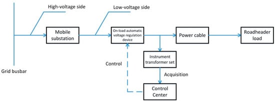
Figure 1.
Voltage Regulation Control Strategy.
3.1. Calculation of Terminal Voltage at the End of the Mining Face
In harsh working environments like coal mines, it is difficult to directly measure the terminal voltage, so it is necessary to introduce a voltage loss algorithm to estimate the terminal voltage. System faults, line parameters, and load power variations, etc. can cause the system voltage to deviate from the nominal value. When considering the voltage loss of the line, the impact of the distributed capacitance of the line is ignorable. The equivalent circuit of the supply line is shown in the equivalent circuit in Figure 2, where R and jX represent the line impedance, and RL and jXL represent the load impedance. The bus voltage U1, after line loss, reaches both ends of the load as U2. The active and reactive powers at the line’s starting end are P1 and Q1, while the powers at the line’s terminal end are P2 and Q2. The complex power at the bus is denoted as S1 = P1 + JQ1, and the complex power at the load is denoted as S2 = P2 + JQ2.
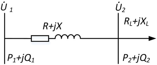
Figure 2.
Equivalent Circuit of the Power Supply Line.
Taking the line’s starting end voltage Ù1 as the reference voltage, let Ù1 = U1∠0°. Suppose that the line’s terminal end voltage is Ù2, then the line current is:
The line’s voltage drop is:
where:
ΔUZ is known as the vertical component of the voltage drop, ΔUH is known as the horizontal component, and φ is the phase angle by which the starting end voltage Ù1 precedes the line current Ì.
From the above equation, the terminal end voltage is expressed as:
where δ is the angle between the line’s starting and terminal end voltages. Generally, U1 − ΔUZ » ΔUH. Equation (5) can be expanded using the binomial theorem, and only the first two terms are considered. We have:
In practical engineering, especially in the power supply systems from industrial and mining enterprises, the angle δ is very small, allowing for further simplification of the above equation by neglecting the third term. The calculation formula of terminal end voltage can be derived as follows:
From the above equation, it is evident that the voltage loss is numerically approximate to the vertical component of voltage drop. The terminal end voltage of the power supply line is related to the line’s starting end voltage, starting end power, and line impedance parameter. In actual line calculations, a voltage and current transformer can be installed at the line’s starting end to measure the line’s starting end voltage, current, and power factor angle. Next, the ending voltage is calculated to achieve the calculation of ending voltage and the estimation of operational status of the long-distance power supply systems.
3.2. Design of a Voltage Regulation Scheme
According to the underground production requirements for coal mines, the ending voltage of a tunneling motor should not be lower than 95% of its rated voltage when operating at rated conditions, and the ending voltage should be greater than 75% of the rated voltage when the motor is started. The on-load automatic voltage regulation device designed in this work is installed in the output circuit on the low-voltage side of the mobile transformer. A shunt branch is added to the secondary side of the mobile transformer and a voltage regulator is added to this branch, hereinafter referred to as the voltage regulation branch. After that, at the end of this voltage regulation branch, a transformer is used in series with the main supply circuit for compensating voltage regulation, hereinafter referred to as the compensation voltage regulation method. The device topology is depicted in Figure 3. In this scheme, the voltage regulator is within the branch, which only needs to withstand part of the load current and input voltage, thus providing higher safety and lower cost.
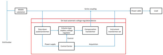
Figure 3.
Topology of the On-load Automatic Voltage Regulation Device.
The secondary winding of the compensation transformer is coupled in series with the main supply circuit. The output voltage of the column-type stepless voltage regulator is added in-phase with the voltage of the main supply circuit to achieve voltage regulation. Based on this topology, a mining explosion-proof on-load automatic voltage regulation device consists of five parts: a step-down autotransformer, a column-type stepless voltage regulator, a compensation transformer, an instrument transformer set, and the control center. In light of the ending voltage estimation theory described in the previous section, an on-load automatic voltage regulation device was designed, with the electrical schematic illustrated in Figure 4. The step-down autotransformer and the compensation transformer in the on-load automatic voltage regulation device are fixed-ratio transformers. The former mainly lowers the voltage to decrease the voltage per turn of coil on the brush sliders of the column-type stepless voltage regulator. The latter couples the regulated voltage to the secondary side of the mobile transformer through two independent windings, which is equivalent to adding a compensating voltage with the same phase and same frequency to the original supply voltage. The three-phase brushes of the voltage regulator are driven by three single-phase AC motors (hereinafter referred to as the voltage regulating motors) to move up and down on a synchronous shaft. The synchronous shaft drives the brushes to slide on the windings, with different positions corresponding to different turns and output voltages.
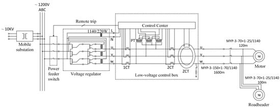
Figure 4.
Design of the Mining Explosion-proof On-load Automatic Voltage Regulation System.
3.3. Design of an On-Load Voltage Regulation Device
Based on the above compensation voltage regulation principle, we proposed a topology of “autotransformer + compensation voltage regulator + compensation transformer”, as shown in Figure 5.
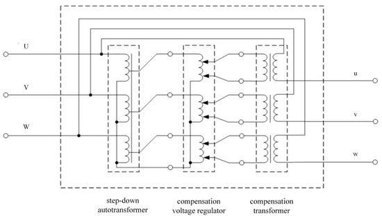
Figure 5.
Topology of the Compensation Voltage Regulation Scheme.
The entire compensation voltage regulation scheme consists of a step-down autotransformer, a compensation voltage regulator, and a compensation transformer. The step-down autotransformer is a single three-phase autotransformer. The connection mode of the primary side is Yn (Y connection with neutral point). The primary side terminal is connected to the output terminal of the low-voltage feeder switch on the mobile substation, while the secondary side terminal is connected to the primary side terminal of the compensation voltage regulator. The step-down autotransformer lowers the voltage from 1140 V to 660 V. The intermediate compensation voltage regulator is composed of three independent single-phase auto-voltage regulators. The connection mode of the primary side is Yn, and the inputs on the secondary side are isolated from each other. Both secondary side terminals are connected to the sliding brush; by changing the position of the contact, an output voltage range of 0 to ±380 V can be achieved. The compensation transformer consists of three independent single-phase isolation transformers. The secondary side terminals of each single-phase voltage regulator are connected to the primary side terminals of the three single-phase isolation transformers. The output coil on the secondary side of the compensation transformer is directly connected in series with the 1140 V circuit to achieve voltage superposition [48,49,50,51]. The output terminal of the series-connected compensation transformer is the output terminal of the whole voltage regulator, with the output voltage being the sum of the output voltage of the mobile substation and the output voltage of the voltage regulator, i.e., 1140 ± 30%V. In the entire topology of the voltage regulator, the step-down autotransformer and the compensation transformer should be transformers with fixed turns ratios. The former serves to change the voltage, while the latter isolates the high-voltage and low-voltage sides, while superimposing the power supply voltages. The compensation voltage regulator that regulates the voltage is a core component of the voltage regulator, which adjusts the voltage by altering the position of the compensation voltage regulator’s brush contact.
- (1)
- Step-down autotransformer
The step-down autotransformer has an input phase voltage of 660 V and an output phase voltage of 380 V. With a power rating of 350 kVA, it is connected to the output side of the mobile substation. We can calculate the secondary side current of the step-down autotransformer as follows:
Compared with ordinary dual-winding transformers, the step-down autotransformer does not need to consider the phase angle difference between the primary and secondary sides. The input and output share the same winding, thus ensuring that the voltage at the output side enters the column-type voltage regulator without any phase angle shift.
- (2)
- Column-type stepless voltage regulator
The column-type stepless voltage regulator is linked to the output side of the step-down autotransformer and consists of three single-phase auto-voltage regulators. The input voltage is 380 V, and the output voltage is (−70%~+130%) × 380 V, also without any phase angle displacement. The primary winding wire is selected based on the rated current of about 307 A, and the secondary winding wire is selected based on the rated current of 600 A.
Each phase of the column-type stepless voltage regulator adopts six column-type iron cores connected in parallel, with six brushes connected in parallel on each side fixed to the same synchronous shaft. The synchronous shaft moves up and down along a guide rail. The top of the voltage regulator has a fixed voltage regulation motor and six balance reactors. The voltage regulation motor drives the synchronous shaft up and down via a chain. The balance reactors help keep the three-phase voltage symmetrical and also play a role in limiting the short-circuit current.
Given the large size and spacing of the three-phase voltage regulator brushes, using a single voltage regulation motor to drive the three-phase brushes requires significant power and poses mechanical balancing challenges. Therefore, three single-phase AC motors are employed to control the three-phase brushes separately. The voltage regulation motor can rotate both forward and backward, corresponding to the upward and downward movements of the brushes. The position of the brushes can be adjusted by controlling the energization time of the motor. Limit switches are installed at the top and bottom of the guide rail, whose normally closed contacts are connected in series with the supply line of the voltage regulation motor. When the brush moves to the top or bottom of the guide rail, the limit switch activates, opening the normally closed contact, and sending a status signal to the control center to stop the voltage regulation motor. The control center controls the forward and reverse rotations of the voltage regulation motor using two relays. The two relays are interlocked so that when the motor is rotating forward, it cannot receive a reverse signal, and vice versa. The control principle for the voltage regulation motor driving the voltage regulator brush is shown in Figure 6.

Figure 6.
Control Principle of Voltage Regulation Motor.
The column-type voltage regulator achieves voltage regulation by changing the turn ratio between primary and secondary windings. Among the mechanical industry standards, Ref. [52], which concerns the voltage regulator, adjusts the turns ratios of primary and secondary windings by altering the contact position between the brush and the polished surface of the column-type winding to achieve the purpose of voltage regulation, which is also detailed in Ref [53]. As shown on the left panel in Figure 7, an ordinary column-type voltage regulator has a high-voltage side connected in a Yn configuration or Y and a low-voltage side connected in Yn configuration. However, the connection mode of the compensation voltage regulator used in this scheme differs from that of an ordinary column-type voltage regulator. It consists of three single-phase autotransformer voltage regulators, with the high-voltage side connected in Y. The low-voltage side outputs are not interconnected. In addition, there is no common terminal between the high and low-voltage sides. The output side should employ a configuration where two contacts are active brushes, located at the front and rear rows of the column-type winding, respectively, as shown on the right panel in Figure 7. The voltage difference between two brushes is adopted as the output voltage of the compensation voltage regulator. When the positions of the two brushes cross, the voltage can be stepped up or stepped down.
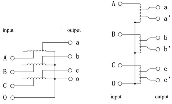
Figure 7.
Ordinary Column-type Voltage Regulator (Left) vs. Proposed Compensation Voltage Regulator (Right).
The iron core of the column-type stepless voltage regulator is wrapped with copper windings in a vertical arrangement, which should be single-layer windings for better heat dissipation. If there is no preceding step-down transformer, the entire 1140 V is applied to the compensation transformer windings. If the number of turns is insufficient, the voltage per turn will be too high. When the brush moves up and down on the winding, it temporarily short-circuits the two adjacent turns of a coil. If the voltage is too high, it can induce an excessive short-circuit current, which will in turn lead to overheating of the winding [54], reduce insulation strength, shorten lifespan, and even create electrical sparks, endangering underground safety. Conversely, increasing the number of turns to reduce inter-turn short-circuit current will also make the column-type core too high. Thus, the specific number of turns must be designed with both constraints in mind.
- (3)
- Compensation transformer
The role of the compensation transformer is to connect the voltage regulated by the column-type stepless voltage regulator in series with the main supply circuit through the secondary winding of the compensation transformer and achieve voltage compensation by adding the original input voltage in-phase with the compensation voltage from the column-type stepless voltage regulator. As depicted in Figure 8, the output terminal of the column-type stepless voltage regulator is connected to the input terminal of the compensation transformer. At this point, the input voltage is the voltage regulated by the column-type stepless voltage regulator.
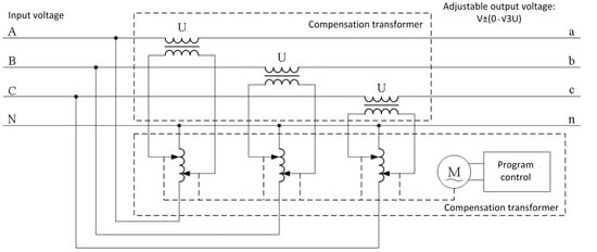
Figure 8.
Wiring Diagram of the Column-style Stepless Voltage Regulator and Compensating Transformer.
Let the input voltage be Ui, the compensation regulator turn ratio be k2, and the compensation transformer turn ratio be k3. Then, the output voltage Uo can be expressed as:
where k3 is a constant and k2 is a variable parameter.
The compensation transformer should employ a transformer with a turn ratio of 380 V/198 V, serving two primary functions in the circuit: one is to change the voltage and connect the output coil in series with a 1140 V circuit to achieve voltage compensation; the other is to provide isolation protection. Unlike ordinary transformers in China, which typically feature concentric windings, isolation transformers are generally produced with primary and secondary windings placed on different core pillars to reduce capacitance between the two [55]. That is to say, the insulation level between the windings of isolation transformers is higher than that of ordinary transformers [56]. As the voltage at the output terminal of the regulator can reach up to 1482 V, using an isolation transformer as the final stage of the voltage regulation system topology not only achieves closed-loop voltage compensation, but also improves the insulation and safety of the system.
- (4)
- Instrument transformer
The control center needs to collect phase voltage, line current, zero-sequence voltage, and zero-sequence current, which requires various transformers, all of which are specially developed. In this table, PT represents a voltage transformer composed of three single-phase voltage transformers with three windings each, connected in Yn/yn/d11. The neutral points on the primary and secondary sides are grounded, with the secondary side star winding used to measure phase-to-phase or phase-to-ground voltage. For the residual windings, the three phases are connected in series from end to end in an open-delta configuration to measure zero-sequence voltage, that is:
To collect three-phase current, two types of current transformers are necessary: a measurement current transformer (1CT) and a protection current transformer (2CT), with the latter having a tenfold turns ratio compared to the former. The calculation of voltage loss demands high precision in measuring line current; however, high-precision current transformers often have limited measurement ranges. During short circuits, the short-circuit current can surge to 10 to 20 times the rated value, quickly saturating the iron core and complicating accurate short-circuit measurements as well as overcurrent protection compliance. On the other hand, current transformers designed for larger measurement ranges usually sacrifice accuracy. To ensure both precise measurements and effective short-circuit protection, two sets of current transformers are utilized, each dedicated to their specific functions. Both sets employ a fully star-connected configuration for three-phase operation.
The zero-sequence current transformer (ZCT) is a through-core transformer to avoid unbalanced currents caused by different excitation characteristics of the transformers. The zero-sequence current is:
The electrical signals collected by the current transformer are then sent to the PLC in the data processing unit for calculation and analysis. Therefore, when designing the transformer parameters, we should not only consider the voltage level and current magnitude on the high-voltage side, but also meet the requirements of the PLC for input signals.
3.4. Control Center
The control part of this scheme utilizes a PLC as the control center and offers high control reliability. When the on-load automatic voltage regulator works, the length of the supply cable on the output side is fixed. By referring to the cable’s impedance parameter, we can determine the total resistance R and reactance X of the cable. The control center is then set with the cable parameter. After measuring the voltage U1 on the output side after compensation voltage regulation, the line current I that passes through the cable and the power factor angle φ using the measurement current transformer and voltage transformer, these signals are input into the control center for processing. The rated motor voltage Us is taken as the reference value, and the voltage U2 at the terminal end of the supply cable can be calculated using Equation (9). By comparing US and U2, when U2 < 0.95 US, the control center will regulate the terminal end voltage positively by controlling the forward motion of the voltage regulator brushes: when U2 > 1.05 US, the control center will regulate the terminal end voltage negatively by controlling the reverse motion of the voltage regulator brushes. When 0.95 US ≤ U2 ≤ 1.05 US, the voltage regulation brushes stops working.
4. Control Mode and Voltage Regulation Strategies
4.1. Control Mode
Since the three-phase brushes are driven by three separate voltage regulation motors, there are two control modes for the voltage regulator brushes: individual phase control and unified three-phase control. Each mode offers distinct advantages and disadvantages.
In the individual phase control mode, the PLC calculates the terminal end voltage of each phase based on the three-phase voltage and current measurements and input line parameters. Then, it outputs three separate control signals to control the forward and reverse rotations of the three-phase voltage regulator motor, respectively, according to the voltage regulation strategy. The three control signals are independent of each other. This control mode allows for independent control of each phase and can automatically balance the device even if the three phases of the grid power supply are unbalanced. However, the control algorithm is complex, requiring three output channels in hardware and an additional balancing control algorithm, with high sensitivity, but poor stability.
In the unified three-phase control mode, the PLC first determines whether the three-phase voltages are balanced according to the three-phase voltage and current measurements. If the voltages are balanced, it proceeds with voltage regulation; otherwise, it issues an alarm. When the absolute value of the imbalance degree ε11 does not exceed 3%, it is considered balanced, as shown in Equation (13):
If the imbalance is induced by inconsistent initial positions of the three-phase brushes, manual voltage step-down or resetting can be employed to align the brushes to the voltage step-down limit switch, thus achieving the balance of three phases. Once balanced, the system will enter automatic voltage regulation mode. This mode ensures that the three phases are balanced before voltage regulation by first checking for balance. Automatic voltage regulation is then performed based on the calculated and set values of the A-phase terminal end voltage with a voltage regulation strategy. The algorithm is simple, requiring only one output channel in hardware. The three phases operate uniformly, avoiding issues with three-phase imbalance induced by inconsistent brush actions during normal operation.
In summary, the unified three-phase control mode offers a simpler algorithm, reliable parallel actions for all phases, and requires fewer hardware and software resources. With this consideration, the unified three-phase control mode is selected, with its control principle illustrated in Figure 9.
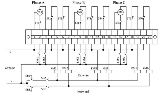
Figure 9.
Unified Three-phase Control Mode.
In this diagram, the buttons SB1 and SB2 represent reverse (voltage step-down) and forward (voltage step-up) control signals given by the PLC, respectively. When the PLC outputs a forward control signal, the coils of the step-up relays KM2, KM4, and KM6 are energized, closing the homonymous normally open contacts. The three-phase motor then starts running forward, driving the brushes and increasing the winding voltage between two brushes in each phase to achieve the step-up of voltage. This continues until the forward signal stops, or a reverse signal arrives, or the forward limit switches ST2, ST4, and ST6 are triggered, which causes the coils of the step-up relays to de-energize and cause the motor to stop running forward. Similarly, when the PLC outputs a reverse control signal, the corresponding step-down relays are KM1, KM3, and KM5, and the corresponding reverse limit switches are ST1, ST3, and ST5. The device is featured with manual reset. When first used, pressing and holding the reset button for 3 s on the initial interface will cause the PLC to output a step-down signal for 20 s to ensure that all three-phase brushes trigger the step-down limit switches, and that the initial positions of the three-phase brushes are consistent and avoid potential three-phase imbalance issues upon first use. The step-down limit switches STa, STb, and STc serve as backup limit protections and are generally not triggered. If an abnormal reset of the device causes the brushes to be misaligned, the limit switches will cut off the corresponding motor.
4.2. Design of Voltage Regulation
The control center is the core of the low-voltage control cabinet and the entire voltage regulation system. It serves not only as the destination for all collected electrical signals after transformation, but also as an execution unit with data processing algorithms and an intermediary for human–machine interaction. Its powerful/robust functions markedly increase the reliability of the voltage regulation device.
Given the harsh environments in underground coal mines, involving numerous signal inputs (both analog and digital) and numerous outputs, a highly reliable PLC was selected as the data processing unit. The RPC2701 high-reliability PLC protector was an intelligent protector that integrated relay protection, comprehensive measurement and control and data communication, and other functions into a single unit. The input and output resources of RPC2701 included: 8 DI, three-phase AC voltage (Ua Ub Uc) and current (Ia Ib Ic), zero-sequence voltage and current (U0 I0), zero-sequence phase angle (Fi0), system voltage (Usys), resistance value (RL) from 1 additional channel of current, total active power (P), power factor (COSφ), 1 channel of resistance (R2); 1 channel of analog input (AI1). All AC data were effective values. The output data included 6 digital outputs (DO). The terminal marking definitions for RPC2701 are shown in Table 3.

Table 3.
Terminal Definitions for RPC2701.
The RPC2701 module also provides an RS232 communication interface to connect with a personal computer (PC) or a display via a programming cable and an RS485 communication interface to communicate with on-site devices.
The PLC module is shown in Figure 10.
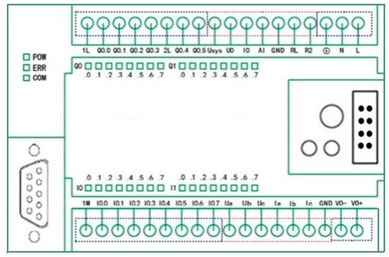
Figure 10.
RPC2701 Module.
Based on the analysis of the signal acquisition section, it was concluded that two sets of current transformers were required to collect the line current. However, the RPC2701 provided only one set of three-phase current input terminals. Hence, an additional RPC2734 dual-combination expansion module was needed to input the second set of three-phase current values. The terminal definitions for the RPC2734 module are shown in Table 4.

Table 4.
Terminal Definitions for the RPC2734 Module.
The RPC2734 module can perform measurements of 6 channels of AC current, 4 channels of leakage resistance, and 1 channel of system voltage. It should be noted that the on-site AC current signals must be converted into AC voltage signals via current transformers before being input into the RPC2734 module. The terminal voltage of the module should not exceed 10 Vrms.
In addition to analog signals like voltage and current, there were also 6 digital inputs. Among them, two bits were occupied by the travel switch signals STH and STL, installed at the bottom and top sides of the guide rail of the compensation voltage regulator. When the motor driving the brush moved to the top or bottom sides of the guide rail, the travel switch would stop the motor and input the motor’s status to the PLC. The remaining 4 digital inputs corresponded to 4 buttons on the human–machine interface, which were utilized to manually adjust voltage, set parameters for the protection device or voltage regulator, etc.
The output signals comprised 3 digital outputs: 2 of which were for the motor’s forward and reverse rotations and used to control the movement direction of the brushes. The remaining 1 was used to control the low-voltage feeder switch of the regulator’s front stage, enabling the quick removal of the regulator in case of a system fault. The I/O allocation is detailed in Table 5.

Table 5.
I/O Allocation Table.
5. Hardware Design and Model Selection for the Voltage Regulation Device
In the previous section, a circuit structure for the voltage regulator based on the autotransformer was presented, and the working principle and feasibility of the regulator was analyzed. In this section, we design various parts of the regulator, including the structures and electrical parameters of the step-down autotransformer, the column-type stepless voltage regulator, and the compensating transformer.
Based on the previous calculations, the rated current is defined as 590 A and the output power of the regulator is calculated based on the maximum output voltage. The maximum output voltage of the regulator is 1482 V. Thus, the output power of the regulator is:
By substituting the data into the equation, we can determine that the output power is 1514 kVA.
The voltage compensation of the regulator is ΔU = 1140 × 30% = 342 V. By substituting the rated current of 590 A into the equation, the compensating power of the regulator is 350 kVA. By the same token, the power of both the step-down autotransformer and the compensating transformer is 350 kVA.
5.1. Design of the Step-Down Autotransformer
The input voltage of the step-down autotransformer is 1140 V, while the output voltage is 660 V, with a turn ratio of 1140 V/660 V. The power of the step-down autotransformer is 350 kVA, and the current at the secondary side of the autotransformer can be calculated as:
The nameplate information of the step-down autotransformer is shown in Table 6.

Table 6.
Parameters of the three-phase Autotransformer.
The external structure of the three-phase autotransformer is shown in Figure 11. The bottom is a steel base, the middle section contains three column-type iron cores, and the top has 3 input terminals and 4 output terminals.
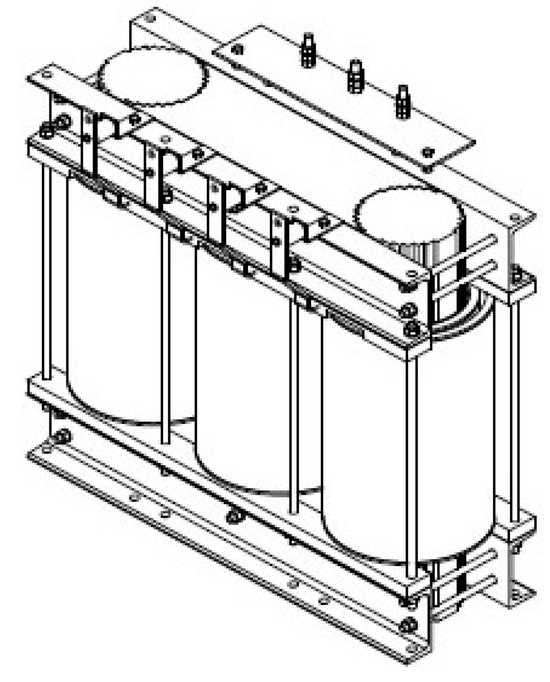
Figure 11.
Overall Appearance of the Three-phase Step-Down Autotransformer.
5.2. Design of the Column-Type Stepless Compensating Voltage Regulator
The compensating voltage regulator is composed of three single-phase column-type stepless autotransformers. The input voltage is 380 V, the output voltage is 0~±380 V, and the rated current is approximately 307 A. Its appearance is shown in Figure 12.
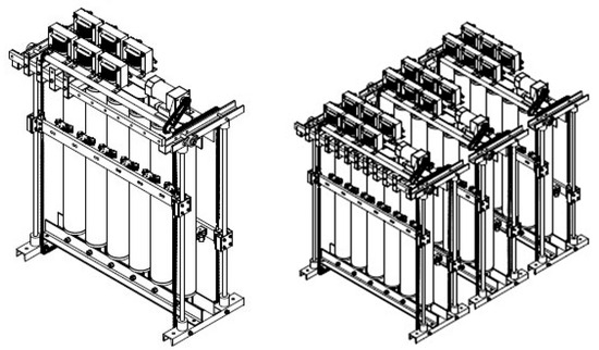
Figure 12.
Overall Appearance of the Single-phase and Combined Column-style Stepless Autotransformer.
As can be seen in Figure 12, six column-type iron cores are arranged in parallel, with six parallel brushes fixed on the same synchronous shaft on each side. The reason for this arrangement is that the connection between the brushes and the coils is through contacts, and the current through the contacts should not be too large during long-term continuous operation. On the other hand, this arrangement can reduce the overall height of the voltage regulator. The allowable current through each column is about 50 A, and six parallel columns can carry a current up to 300 A.
The voltage regulator has guide rails at its four corners, running from the bottom to the top, which support the regulator, while allowing the synchronous shafts on both sides to move up and down along the rails. The top of the regulator is a fixed motor and six balancing reactors. The motor controls the variation of the position of the synchronous shafts via a chain. The balancing reactors serve two primary purposes. Firstly, they balance the current of the six parallel windings. Each reactor has two branches, which are used to balance the current between the two branches. These branches exhibit mutual inductance effects. When the current between the branches is unbalanced due to mutual inductance, the reactance of the branch with lower current decreases, causing its current to increase, while the reactance of the branch with higher current increases, causing its current to decrease. This helps balance the current. Secondly, it limits short-circuit current. Considering that there is direct electrical contact between the primary and secondary sides of the autotransformer and that the short-circuit impedance of the autotransformer is smaller than that of a dual-winding transformer, the short-circuit current is larger. The presence of balancing reactors increases the overall short-circuit impedance, thus limiting the short-circuit current. The physical appearance of the voltage regulator is illustrated in Figure 13.
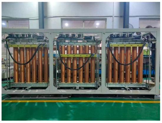
Figure 13.
Physical Appearance of the Column-style Stepless Autotransformer.
5.3. Design of the Compensating Transformer
The compensating transformer consists of three single-phase isolation transformers with a turn ratio of 380 V/198 V, which mainly serves two functions in the circuit: firstly, to adjust the voltage and connect the output winding in series with a 1140 V circuit to achieve the purpose of voltage compensation; secondly, to provide isolation protection. The nameplate information of the compensating transformer is shown in Table 7.

Table 7.
Parameters of the Compensating Transformer.
The compensating transformer is illustrated in Figure 14. Each single-phase transformer has two column-style iron cores and two input/output terminals.
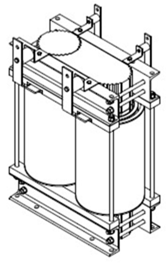
Figure 14.
Compensating Transformer (Single-phase).
5.4. Signal Acquisition
As analyzed earlier, the losses in the line vary with the working current of the equipment at the end of the line. Thus, to accurately compensate for the line losses, it is required to collect electrical signals from the line in a real-time manner, including three-phase voltage, three-phase current, zero-sequence voltage and zero-sequence current. Only after collecting electrical signals can the status of the terminal equipment be determined, and the required compensation amount be calculated. The electrical signals collected by the instrument transformer are sent to the PLC in the data processing unit for calculation and analysis. So, when selecting the model of instrument transformer, it is necessary to consider not only the voltage level and current size on the high-voltage side, but also the requirements of the PLC for input signals. Building on this, the main parameters of the instrument transformer are established, as presented in Table 8. The physical appearance of the voltage instrument transformer, current protecting instrument transformer, and current measuring instrument transformer is shown in Figure 15.

Table 8.
Parameters of the Instrument Transformer.
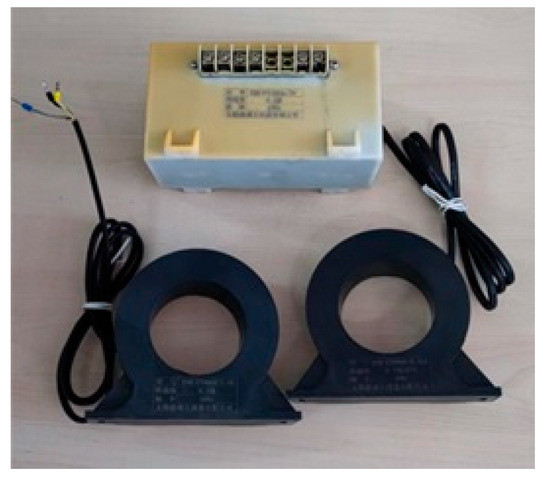
Figure 15.
Picture of mutual inductor.
5.5. Enclosure Design
Given the presence of explosive gases like methane in underground coal mines, the voltage regulator’s core must be placed within an explosion-proof enclosure. This enclosure should comply with the requirements of GB3836 and possess sufficient structural strength. During type testing, the enclosure must not transmit an explosion or deform. The enclosure is made of 15 mm steel plates welded together, with explosion-proof surfaces designed at the entry/exit of the cable and between the cover and the enclosure body as required. Moreover, due to the large number of electrical components inside, heat dissipation should also be considered. Thus, radiating fins are added to the enclosure. The enclosure is composed of two parts: a mining explosion-proof dry-type on-load voltage regulator (located in the main chamber) and a mining explosion-proof on-load voltage regulation control and protection unit (located in the auxiliary chamber). The two parts have independent explosion-proof housing and are connected by flanges. The overall appearance of the voltage regulator is shown in Figure 16.
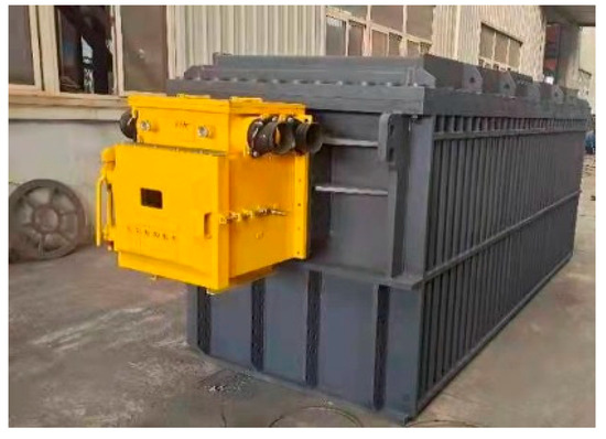
Figure 16.
Overall Appearance of the Voltage Regulator.
6. Application of the On-Load Voltage Regulation Device
6.1. Application of the On-Load Voltage Regulation Device in Underground Coal Mines
Wanli No. 1 is located in the northwest of Ordos City, Inner Mongolia Autonomous Region. It is a large-scale integrated modern mine with an approved production capacity of 10 million tons per year. By the end of 2022, the remaining recoverable reserves had been 865 million tons. To meet production needs, the mining faces are consistently extending. Taking the power distribution point at No. 10 Connecting Roadway in the 42304 main and auxiliary crossheadings as an example, the distance between production equipment (miner-bolter, vehicle No.1, and conveyor drive) and the power distribution point has grown, currently reaching up to 2000 m and potentially extending to 3000 m in the future, as illustrated in Figure 17. The model of the underground mobile transformer is KBSGZY-2000/10, installed at No. 10 Connecting Roadway in the 42304 main and auxiliary haulage roadways, the input voltage from the Substation for Panel 3, Coal Seam 42 is 10 kV, and the output voltage is 1140 V. After passing through the KBZ16-630/1140 explosion-proof switch, the on-load voltage regulation device is connected, and then through an MYP-3 × 150 + 1 × 70 transmission cable, with a length of 3000 m, the power is supplied to the equipment at the tunneling face of the 42304 main and auxiliary haulage roadways.
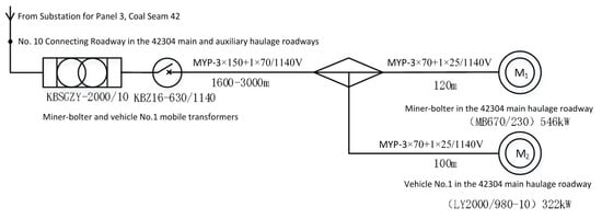
Figure 17.
Simplified Schematic of the Power Supply System for the Miner-bolter and Vehicle No. 1.
To address the problem of voltage fluctuations over long-distance power supply, the on-load voltage regulation device is arranged at the rear end of the mobile transformer. A KBZ16-630 switch is installed between two devices to facilitate power supply. The on-load voltage regulation device operates in a stable and reliable manner, improving the power supply quality at the mining face, reducing downtime caused by voltage fluctuations, and ensuring the smooth advancement of tunnel excavation from 2000 m to 3000 m. The human–machine interface is shown in Figure 18.
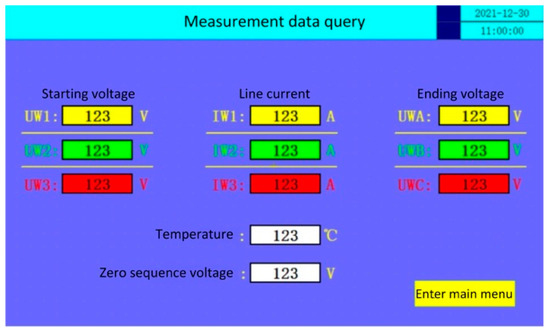
Figure 18.
Human–machine interface.
6.2. Simulation and Analysis of the On-Load Voltage Regulation Device
A comparison between the voltage of the original end of line at Wanli No. 1 and the voltage after applying the “autotransformer + compensating voltage regulator + compensating transformer” voltage regulation technology is shown in Figure 19.
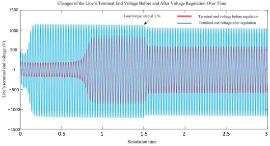
Figure 19.
Comparison of Terminal End Voltages before and after Voltage Regulation.
The red line represents the line’s terminal end voltage before voltage regulation, while the blue line represents the voltage after regulation. During the low voltage phase, which corresponds to the motor’s no-load startup process, at 1.5 s, 80% of the rated load is applied. It can be observed that the motor starts slowly before voltage regulation. The overall voltage level is low and experiences significant voltage drop under load, resulting in poor voltage stability throughout the process. In contrast, after voltage regulation, the motor starts quickly, keeps the overall voltage at the rated level, and experiences minimal voltage drop under load. Compared with before, the overall voltage stability is significantly improved after regulation.
After employing the compensation voltage regulation scheme presented in this paper, the power factors under different load rates are shown in Figure 20.
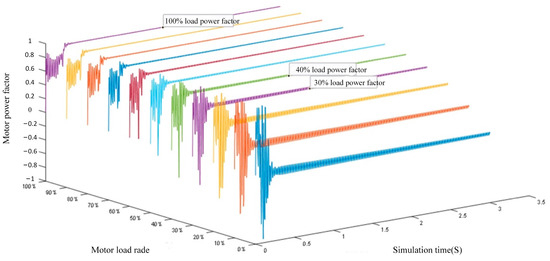
Figure 20.
Power Factor after Applying the Compensation Voltage Regulation Scheme.
It can be easily observed that the motor’s power factor increases as the load rate approaches the rated torque, indicating a significant improvement in the load-carrying capacity after voltage regulation. At 40% of the rated load, the power factor grows to 0.7804, and at 100% of the rated load, it grows to 0.9359, which is 1.61 times higher than before regulation. A comparison of the current power factor for long-distance power supply at Wanli Colliery 1 and the power factor after applying the compensation voltage regulation scheme (Figure 17) yields Figure 21.
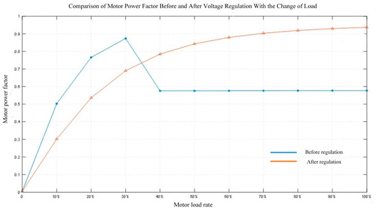
Figure 21.
Comparison of Power Factor Before and After Voltage Regulation With the Change of Load.
It is evident that before the compensation voltage regulation device is put into operation, the system can only start and run normally with 30% of the rated load. After applying the compensation voltage regulation scheme, the system can start and run at 100% of the rated load and even overload, along with a significant improvement in the power factor.
6.3. Automatic Voltage Regulation Test
Voltage regulation accuracy is one of the key characteristics of a power system and plays a crucial role in guaranteeing the safe, stable and reliable operation of the power system. By conducting an automatic voltage regulation test, we can verify the performance of the regulator and the control logic of the control center, calculate the error range between the terminal voltage and the target voltage based on experimental data, and evaluate the steady-state precision of the system. The on-load voltage regulation device was applied to the tunneling face of the 42304 main and auxiliary haulage roadways in Wanli No. 1.
The data of the automatic voltage regulation test are shown in Table 9. The voltage regulation accuracy was calculated, and it was found that the voltage regulation accuracy for ending voltage was basically within ±5% of the set value of 660 V. The voltage regulation effect was good, with some data exceeding this error range because of considerable fluctuations in the three-phase load at the experimental site, which caused instability in the three-phase voltage of the experimental power source. It can be seen that the automatic voltage regulation system was able to ensure that the equipment operated within the set voltage, avoiding losses caused by excessive or insufficient voltage, with fast response and high reliability, and the error was within ±5%, which meet the requirements of actual applications.

Table 9.
Voltage Data for the Automatic Voltage Regulation Test.
7. Conclusions
In light of the status quo of a long-distance power supply system at the tunneling faces of coal mines, this paper analyzed the shortcomings and deficiencies of existing solutions, compared the design approaches of different voltage regulation systems, carried out theoretical analysis and calculations on long-distance power supply voltage loss, a calculation method was proposed that enabled the prediction of the voltage at the end of the cable line based on the parameters at the start of the line. This method utilizes cable parameters, measured starting voltage, line current, and other parameters to estimate the ending voltage via a software algorithm, providing a basis for voltage regulation. Furthermore, a novel mine-duty on-load voltage regulation topology for voltage reduction compensation after voltage was reduced based on branching was presented. The topology enabled real-time compensation for voltage drop along the line, overcoming limitations of existing voltage regulation technologies and achieving fast, smooth and stepless voltage regulation to satisfy the requirements of motor startup and operation at the end of the line. Concurrently, a compensation-based voltage regulation technology was developed, structured around the “autotransformer + compensation voltage regulator + compensation transformer” configuration. Building upon this approach, an on-load voltage regulation device for 1140 V long-distance power supply in underground coal mines was successfully developed. This device addressed issues such as excessive voltage loss, too low ending voltage, and malfunction of roadheader motors in long-distance power supply systems (5000 m). To ensure the safety of the regulator itself and take into account the surge resistance of the powered equipment, the regulation speed of the regulator was limited to 3% of the rated voltage per second. This device was applied to the long-distance power supply system of Wanli No. 1’s tunneling faces, meeting the design requirements in terms of technical performance and stability, etc. It ensured full-load startup of motor and normal operation at the end of the line, dramatically improved the system’s load-carrying capacity, stabilized the ending voltage, reduced energy losses at the tunneling faces, and minimized the occurrence of power supply accidents. This solution fundamentally addresses the voltage fluctuation issues in long-distance power supply at the excavation faced of coal mines and ensures the electrical safety of tunneling faces. The proposed technical device can not only be popularized and used in underground coal mines, but can also be utilized in non-coal mines, metro, tunnels, and other working scenarios that required long-distance power supply. Since the device included hardware such as column-type regulators and transformers, it was relatively large and heavy. Further exploration is needed regarding the use of power electronics for voltage regulation, although challenges such as heat dissipation and explosion-proof suitability for underground coal mines must also be addressed.
Author Contributions
Conceptualization, W.F.; methodology, Y.X.; software, L.Z.; validation, Y.X. and T.L.; formal analysis, W.F.; investigation, L.Z. and T.L.; resources, Y.X.; data curation, L.Z.; writing—original draft preparation, T.L.; writing—review and editing, W.F.; visualization, L.Z.; supervision, Y.X.; project administration, T.L.; funding acquisition, W.F. All authors have read and agreed to the published version of the manuscript.
Funding
This research received no external funding.
Institutional Review Board Statement
Not applicable.
Informed Consent Statement
Not applicable.
Data Availability Statement
The data presented in this study are available on request from the corresponding author.
Conflicts of Interest
Authors Wenjun Fu, Liang Zhang were employed by the company Beijing China Coal Mine Engineering Co., Ltd. The remaining authors declare that the research was conducted in the absence of any commercial or financial relationships that could be construed as potential conflicts of interest.
References
- Liu, H.; Hu, Y.; Miao, S.; Zhao, M. Study on the characteristics of coal resource flow and carbon emission calculation in china under the background of “double carbon”. Coal Econ. Res. 2025, 1, 6–16. [Google Scholar] [CrossRef]
- Liang, Y. Theory and technology considerations on high-quality development of coal main energy security in China. Bull. Chin. Acad. Sci. 2023, 1, 11–22. [Google Scholar] [CrossRef]
- Li, X. Research on development of new energy transportation technology in open-pit coal mines in China under background of “dual carbon”. Opencast Min. Technol. 2025, 4, 39–42. [Google Scholar] [CrossRef]
- Su, G.; Shuai, H.X.; Guo, Y.C.; Hu, K.; Zhao, D.Y.; Pang, Z.J. Research on the relative pose detection method of the joint unit of the excavation and support anchor robot based on infrared thermal imaging. J. Coal Ind. 2025, 10, 4640–4653. [Google Scholar] [CrossRef]
- Su, J.; Du, B.; Li, J.; Li, Z. Electrical tree degradation in high-voltage cable insulation: Progress ang challenges. High Volt. 2020, 4, 353–364. [Google Scholar] [CrossRef]
- Li, J.L.; Ye, X. Analysis of characteristics and patterns of coal mine accidents in China from 2018 to 2023. Saf. Coal Mines 2025, 10, 248–256. [Google Scholar] [CrossRef]
- Zheng, R.J. Research on Underground Coal Mine Power Monitoring System. Energy Energy Conserv. 2025, 9, 111–113. [Google Scholar] [CrossRef]
- Ren, X.W.; Wang, Z.X.; Wang, R. Study on fire hazard of cable in coal mine. Saf. Coal Mines 2022, 9, 151–156. [Google Scholar] [CrossRef]
- Yin, Y.; Zhang, G.H.; Wang, H.L. Analysis of the impact of grid voltage and frequency fluctuations on the operation of large generators. Shanghai Medium Large Electr. Mach. 2023, 4, 55–59. [Google Scholar] [CrossRef]
- Li, W.; Zhang, Y.L. Research on the harm of voltage fluctuations in the power grid to frequency converters and their solutions. Electron. Compon. Inf. Technol. 2022, 12, 198–201. [Google Scholar] [CrossRef]
- Lan, J.; Lin, Y.; Fang, X.; Lin, J.; Chen, Y. Pre-assessment of Harmonic Pollution in Power Grid Considering Uncertainties in Renewable Energy. Proc. CSU-EPSA 2024, 8, 1–12. [Google Scholar] [CrossRef]
- Li, D.J.; Shi, Y.X.; Li, A.G. Research on Application of Cascaded Multi-level Active Power Filter on Harmonic Compensation of Coal Mine Power Grid. Coal Mine Mach. 2023, 8, 154–156. [Google Scholar] [CrossRef]
- Hou, L.B.; Chen, J.; Li, C.Y. Accelerated Thermal Ageing Characteristics ofXLPE Cable Insulation. Insul. Mater. 2020, 2, 59–63. [Google Scholar] [CrossRef]
- Cao, S. Application of Combined Analysis of Cable Partial Discharge Test and Thermal Aging Test in Predicting the Life of Power Equipment. Sci. Technol. Innov. 2025, 17, 219–221+225. [Google Scholar] [CrossRef]
- Xia, S.Y.; Fan, J.; Dong, X. A method of calculating fault rate of power cables based on the influence of temperature changes. Electr. Eng. 2024, 5, 122–124. [Google Scholar] [CrossRef]
- Zhang, J.; Li, S.F.; Guo, X. Quick evaluation method for electrical life of XLPE insulation material used in HV cables. Opt. Fiber Electr. Cable Their Appl. 2024, 2, 38–41. [Google Scholar] [CrossRef]
- Xiaofeng, W.; Xiaodong, Y.; Chong, L. Study on monitoring and measuring technology of high reliability insulation for high voltage cable in underground mine. Mine construction technology 2020, 06, 58–61. [Google Scholar] [CrossRef]
- Ding, Y. A review of partial discharge detection methods: Current status and future directions. Hydropower New Energy 2025, 9, 46–49. [Google Scholar] [CrossRef]
- Yin, Y.; Shi, H.Y.; Liu, C. Research Progress on Artificial Intelligence for Partial Discharge Diagnosis in Power Cables. High Volt. Eng. 2025, 9, 1–19. [Google Scholar] [CrossRef]
- Fan, J.; Li, M.; Zhang, P.Y. Experimental study on the combustion and explosion process induced by theentrainment of deposited coal dust. Chin. J. Eng. 2025, 8, 1602–1615. [Google Scholar] [CrossRef]
- Zhang, X.B.; Wang, Y.F.; Guo, J.L. Propagation law of gas-coal dust explosion shock waves under different explosion conditions. J. Mine Autom. 2025, 10, 104–113. [Google Scholar] [CrossRef]
- Dai, Z.Y. Research progress on prevention and control technology of coal mine dust and gas explosions. Coal Chem. Ind. 2025, 3, 99–103+114. [Google Scholar] [CrossRef]
- Yuan, C.M.; Shi, K.W.; Li, G. Research progress on ignition and explosion characteristics of gas and coal dust and their mixtures. Min. Saf. Environ. Prot. 2024, 6, 42–53. [Google Scholar] [CrossRef]
- Ding, Q.Q.; Shuai, H.; Chen, J.Y. Analysis and Treatment on 220 kV Substation Power Off Accident Caused by Cable Terminal Fault. Wire Cable 2021, 1, 35–38. [Google Scholar] [CrossRef]
- Fan, W.J. Temperature monitoring technology of coal mine high voltage cable based on infrared non-contact cable type. Saf. Coal Mines 2020, 11, 106–112. [Google Scholar] [CrossRef]
- Zhang, M.H.; Wang, H. Cause analysis of coal mine power supply accidents based on accident tree method. Inn. Mong. Coal Econ. 2020, 24, 115–117. [Google Scholar] [CrossRef]
- Li, W.Q.; Zhang, Y.L. Study of comprehensive evaluation on air quality in mine based on matter element model. Min. Res. Dev. 2015, 3, 61–63. [Google Scholar] [CrossRef]
- Yang, X.; Miao, H.; Hui, H. On the Measurement and Improvement of the Underground Environment Parameters of the Plateau Mine. Miner. Eng. Res. 2020, 2, 49–54. [Google Scholar] [CrossRef]
- Chen, Y.M.; Li, W.X. Preventive Measures and Implementation Effect Evaluation of Gas Explosion Accidents in Underground Coal Mines. Energy Energy Conserv. 2025, 6, 273–276. [Google Scholar] [CrossRef]
- Gao, L.; Cheng, W.D.; Bai, L.L.; Xiao, L.M.; Xiao, E.X.; Zhang, L.J. Thermal oxidative aging ERP cable insulation partial discharge characteristics and degradation mechanism. High Volt. Electr. Technol. 2021, 1, 231–240. [Google Scholar] [CrossRef]
- A, A.J. Research on Power Quality Monitoring and Governance Technology of Power Distribution System. Autom. Appl. 2025, 12, 135–138. [Google Scholar] [CrossRef]
- Xia, K. Discussion on long distance power supply in fully mechanized coal face. Coal Eng. 2020, 6, 48–50. [Google Scholar]
- Liu, S.; Hongliang, P.; Dongyu, X. Voltage and reactive power coordinated control strategy for flexible on load tap changers. Electric Power Engineering Technology 2024, 10, 124–132. [Google Scholar] [CrossRef]
- Cao, M.; Yuan, H.C.; Zhang, Y.T. Analysis of Common Causes of Faults in On-load Tap-changers for Distribution Transformers and Measures to Improve Product Reliability. Transformer 2025, 8, 14–20. [Google Scholar] [CrossRef]
- Yuan, J.J.; Zhang, L.L.; Wang, Y.F. On load automatic voltage regulation technology and device of power supply system in heading face. Saf. Coal Mines 2024, 5, 243–250. [Google Scholar] [CrossRef]
- Li, H.Y.; Zhang, Q.; Fan, T.C. Research on Electromagnetic Radiation Characteristics of On-load Tap Changer Switching under Different Contact States. High Volt. Appar. 2025, 6, 1–10. [Google Scholar]
- Wang, Y.; Zhang, T. A hybrid voltage regulator with arcless tap change and stepless voltage regulation functions. In Proceedings of the 2020 IEEE Energy Conversion Congress and Exposition (ECCE), Phoenix, MI, USA, 11–15 October 2020. [Google Scholar]
- Li, P.Y.; Guo, W.H.; Yao, S. Automated diagnosis system for transformer on load tap changer faults based on improved neural network. Autom. Instrum. 2025, 7, 68–72. [Google Scholar] [CrossRef]
- Li, Y.Q.; Guo, Y.N.; Wang, L. Reliability verification and optimization of split-type on-load tap changer structure. Electr. Mach. Control 2025, 7, 12–21. [Google Scholar] [CrossRef]
- Chen, P.; Lei, L.; Yao, S.K. Research on On-load Tap-changing Technology of Distribution Transformer Based on Power Electronic Devices. Transformer 2021, 2, 30–35. [Google Scholar] [CrossRef]
- Gao, G.Y.; Dong, R.; Xiao, X.Q.; Hou, R.; Dong, F. Study on Power Electronics Application in On-load Tap Changer. Electr. Drive 2021, 6, 73–80. [Google Scholar] [CrossRef]
- Yao, S.D.; Zhang, Z.K.; Zhang, X.W.; Gao, X.Y.; Cai, C.H.; Zhou, X. Research on On-load Voltage Regulating Transformer Based on Power Electronic Switch. Electr. Drive 2022, 19, 33–38. [Google Scholar] [CrossRef]
- Li, W.R.; Shi, H.J. Research on Load Tap Changer Based on Power Electronic Switch. Autom. Appl. 2023, 8, 99–102. [Google Scholar]
- Alsuwaidi, H.; Adam, A. Design and simulation of a seven taps electronic on load tap changer in 11/0.4kV distribution transformers using a PI controller. In Proceedings of the International Conference on Electrical and Computing Technologies and Applications (ICECTA), Ras Al Khaimah, United Arab Emirates, 1–31 December 2019. [Google Scholar]
- Li, C.; Huang, C.; Ren, L.; Bouhorma, M.; Maataoui, Y. On-load tap-changer control by a fuzzy logic controller. In Proceedings of the 2019 4th World Conference on Complex Systems (WCCS), Valzazat, Morocco, 1–31 December 2019. [Google Scholar]
- Zhang, C.H. Application research on dynamic reactive power compensation device (SVC) in coal mine power supply system. Mech. Manag. Dev. 2020, 7, 156–157+182. [Google Scholar] [CrossRef]
- Lei, L.; Zhang, Z.X.; Lei, Z. Application of Dynamic Reactive Power Compensation Device in Coal Mine Power Supply System. Coal Technol. 2020, 5, 171–173. [Google Scholar] [CrossRef]
- Li, B.W.; Xiao, J.Z.; Xiao, S.W. Model of a Multi-Rate Interface Transformer Incorporating Considerations for Capacitive Reactive Power Compensation and Transient Oscillation Suppression. Proc. CSEE 2025, 3, 1–12. [Google Scholar] [CrossRef]
- Yao, H.B.; Mu, Q.; Xiao, C. Integrity verification of transformer secondary current circuit based oncapacitor compensation. Electron. Des. Eng. 2025, 9, 115–119. [Google Scholar] [CrossRef]
- Wang, S.Q.; Chen, G.; Li, Y.T. Research on Low-Voltage Control Method Based on Series Voltage Compensation Control. J. Northeast Electr. Power Univ. 2024, 5, 42–49. [Google Scholar] [CrossRef]
- Yuan, J.J.; Zhang, L.L.; Wang, Y.F. Integrated voltage regulation and control technology of long-distance power supply systemin Wanli No.1 Mine. Saf. Coal Mines 2023, 12, 251–256. [Google Scholar] [CrossRef]
- Li, W.; Li, W.H.; Li, X.F. Transformation and Application of Intelligent Pressure Regulating Device for Excavating Face. Mech. Manag. Dev. 2025, 9, 132–134. [Google Scholar] [CrossRef]
- Ding, L.Y.; Huang, H.R. Structural analysis of neutral point voltage regulating single-phase autotransformer. Transformer 2020, 9, 5–6. [Google Scholar] [CrossRef]
- Zhang, X.; Wei, C.; Wu, Y.; Lv, Z.; Ma, X.; Lu, Y.; Huang, B. Inter-turn fault diagnosis of dry-type transformers based on flux leakage. Power Syst. Clean Energy 2021, 11, 55–62. [Google Scholar]
- Ge, S.; Liu, W.; Ding, D.; Li, X. Electromagnetic Disturbance Coupling and Suppression of On-site Electronic Device Power Port in Substations. High Volt. Eng. 2021, 12, 4483–4492. [Google Scholar] [CrossRef]
- Yu, P.; Wei, W. Analysis of the use of isolation transformer. Energy Sav. Nonferrous Metall. 2021, 3, 70–74. [Google Scholar] [CrossRef]
Disclaimer/Publisher’s Note: The statements, opinions and data contained in all publications are solely those of the individual author(s) and contributor(s) and not of MDPI and/or the editor(s). MDPI and/or the editor(s) disclaim responsibility for any injury to people or property resulting from any ideas, methods, instructions or products referred to in the content. |
© 2025 by the authors. Licensee MDPI, Basel, Switzerland. This article is an open access article distributed under the terms and conditions of the Creative Commons Attribution (CC BY) license (https://creativecommons.org/licenses/by/4.0/).
