Article

Design and Performance Evaluation of an Automated Bud Grafting Machine for Cucurbitaceous Seedlings

1
College of Electromechanical Engineering, Xinjiang Agricultural University, Urumqi 830052, China
2
Institute of Agricultural Mechanization, Xinjiang Academy of Agricultural Sciences, Urumqi 830091, China
3
Xinjiang Facility Agriculture Engineering, Equipment Technology Research Center, Urumqi 830091, China
*
Authors to whom correspondence should be addressed.
Processes 2025, 13(12), 3788; https://doi.org/10.3390/pr13123788
Submission received: 20 October 2025 / Revised: 17 November 2025 / Accepted: 20 November 2025 / Published: 24 November 2025

Abstract

With the rapid development of the vegetable industry and the accelerating pace of population aging, mechanization in the core production process of vegetable seedling grafting has become an inevitable trend. To address this, various vegetable grafting devices have been developed globally. However, most existing equipment exhibits limited automation and is prone to damaging young plant stems during operation. To effectively reduce seedling injury, improve grafting quality, and increase success rates, this study focused on tray seedlings of cucurbitaceous vegetables as grafting subjects. Based on the bud grafting method, we conducted mechanistic analysis and structural design for the cutting module, the integrated clamping and grafting mechanism, and the clip supply and binding system. Experiments were carried out at the Protected Agriculture Demonstration Base in Ke Township, Yecheng County, Kashgar Prefecture, Xinjiang. The study adopted the multiple-group repeated experiment verification method, and completed verification through cutting tests and grafting efficiency tests. Specifically, 250 rootstocks and 250 scions were selected for the cutting tests, while 500 rootstocks and 500 scions were selected for the grafting efficiency tests; both tests were divided into 5 groups, and the data were analyzed using descriptive statistical analysis. Cutting trials and clamping performance tests demonstrated that the designed mechanism improves the precision of alignment between rootstock and scion cuts while minimizing potential damage during clamping, confirming the rationality of the design. The overall performance was further validated in grafting trials using Qingyan rootstock No. 1 pumpkin and Yongtian No. 5 melon as scions. Results showed that with rootstock and scion cutting angles set at 30° and 25°, respectively, and corresponding cut surface lengths of 6.34 ± 0.18 mm and 6.29 ± 0.14 mm, the device achieved a grafting efficiency of 1400 plants per hour with an average success rate of 90%, and no obvious stem damage was observed during the clamping process. These results demonstrate that the proposed grafting machine design is effective in enhancing both grafting efficiency and quality.

1. Introduction

China ranks as the global leader in both vegetable production and consumption. Within the agricultural sector, vegetables hold a position second only to staple crops [1,2]. With the rapid expansion of the vegetable industry, coupled with the increasingly constrained availability of land resources, the practice of continuous cropping is becoming increasingly commonplace [3]. Long-term continuous cropping not only leads to a persistent decline in soil quality, but also renders the inherent deficiencies of native seedlings increasingly apparent [4,5]. The prolonged growth cycle and limited stress tolerance of these crops have become key factors constraining both yield enhancement and quality optimization within the vegetable industry. Grafting techniques for seedling propagation offer an effective solution to mitigate the adverse effects of continuous cropping [6,7,8,9,10]. Traditional manual grafting methods are labour-intensive, time-consuming and physically demanding, rendering them inadequate for meeting the current vegetable seedling industry’s demand for standardized, large-scale production. Consequently, advancing mechanisation to replace grafting operations at critical production stages has become an inevitable direction for the sector’s development [11,12].
From the 1980s to the present, overseas agricultural machinery companies and research bodies have tackled technical hurdles in vegetable grafting equipment, achieving the successful development of various machine models rooted in distinct grafting methods [13,14]. The technological development of ISEKI Co., Ltd. in the field of cucurbit grafting machines demonstrates a clear phased advancement. In 1994, the company took the lead in collaborating with biological research institutions and successfully developed the GR800B semi-automatic cucurbit grafting machine based on the core technology of the top-grafting method, laying the foundation for the mechanization of grafting operations for cucurbit crops. Subsequently, to further optimize equipment performance and adapt to agricultural production needs, ISEKI Co., Ltd. once again joined hands with biological research institutions in 2011 to launch the upgraded model GRF803-U grafting machine [15]. The GRF803-U is a semi-automatic model that adopts manual seedling feeding. Based on the top-grafting method, it features a high degree of automation with a productivity of 800 plants per hour and a grafting success rate of 95%. However, the vibratory bowl clip feeding mechanism of this grafting machine is prone to clip jamming and blockage. In 2016, South Korea’s Daedong Electromechanics Co., Ltd. launched the AFGR-800CS multi-functional fully automatic grafting machine. This machine can automatically complete operational processes such as cutting and clamping of scions and rootstocks. Its most prominent feature is its capability to utilize a machine vision camera and image processing technology to achieve perfect alignment of the cut surfaces between the rootstock and scion. After the joining process is completed, the grafted seedlings are transported out through a conveyor belt [16]. The Graft1000 tubular grafting equipment developed by the Netherlands-based ISO Group incorporates image processing technology to achieve precise screening and removal of substandard seedlings prior to grafting. However, during practical application, the device has revealed issues such as stringent requirements for seedling age control and the need for frequent replacement of tubular clamps during production. Consequently, it has proven difficult to promote its use among seedling enterprises with lower levels of seedling standardization [17].
Compared to countries such as South Korea, Japan, and the Netherlands, China entered the field of vegetable grafting robotics relatively late, with research and development primarily undertaken by higher education institutions and research institutes. Starting from the 1990s, after close to three decades of continuous development, China has achieved significant advancements in the R&D of vegetable grafting machinery [18,19]. Within China’s vegetable grafting equipment R&D sector, multiple core teams have achieved significant results, developing differentiated types of grafting machines tailored to distinct application scenarios [20,21,22,23,24,25]. Owing to the inherent growth limitations of cucurbit seedlings, the majority of cucurbit grafting equipment developed globally at present is of the semi-automatic variety [16,26,27,28]. Although the basic model can independently complete the core grafting process, research into its protective mechanisms for seedlings remains insufficient, resulting in frequent damage to seedlings during grafting operations [29]. There are certain limitations in China’s research on Cucurbitaceae grafting technology [19,30,31,32]: Firstly, at the mechanistic level, the influence mechanism of cutting angle on the fit effect of the cut surfaces between rootstock and scion lacks systematic elaboration, resulting in insufficient theoretical support for equipment cutting parameters. Secondly, considering the biological characteristics of complex pith cavity structures inside the stems of Cucurbitaceae seedlings, existing equipment has insufficient precision cutting and grafting capabilities, failing to achieve complete removal of the growing point and high-precision docking of the cut surfaces, which directly affects the grafting survival rate. Furthermore, the structural design of the grafting clip feeding device has flaws, prone to clip jamming and blockage due to issues such as clip posture deviation and feeding channel jamming, restricting the continuity and stability of grafting operations. Therefore, this research will be carried out with three aims: first, to clarify the mechanism of action of cutting angle on the fit effect and establish a basic theoretical model for parameter regulation; second, aiming at the seedling pith cavity structure, to design an adaptive cutting module and precise docking mechanism to achieve complete removal of the growing point and tight bonding of the cut surfaces; third, to optimize the structural design of the grafting clip feeding device, improve the feeding mechanism and clip guiding mechanism to solve the problems of clip jamming and blockage, ensuring operational continuity. This equipment innovatively adopts synchronous cutting and grafting technology, where the scion only needs to slide horizontally to the rootstock cutting surface, which can effectively avoid lateral deviation of seedlings and significantly improve the grafting success rate. The design of the clip feeding device of the Cucurbitaceae grafting machine is optimized, using a two-stage linear vibration clip mechanism combined with a photoelectric distance measuring sensor, which significantly improves the stability of clip feeding and binding.
The specific objectives of this research are:
(1)
To reveal the mechanism of seedling damage during the clamping, cutting, and bonding processes of Cucurbitaceae seedlings, and establish an integrated automatic grafting machine integrating “clamping-cutting-bonding-binding”;
(2)
To realize automatic grafting operations for Cucurbitaceae plug seedlings, with core technical indicators reaching: seedling damage rate less than 3%, grafting efficiency greater than 1400 plants per hour, interface fit degree greater than 95%, and grafting success rate greater than 90%;
(3)
To provide efficient and low-damage automatic equipment for large-scale grafting of Cucurbitaceae vegetables, promoting highly automated operations in the grafting link of protected agriculture.

2. Materials and Methods

2.1. General Design of the Vegetable Grafting Machine

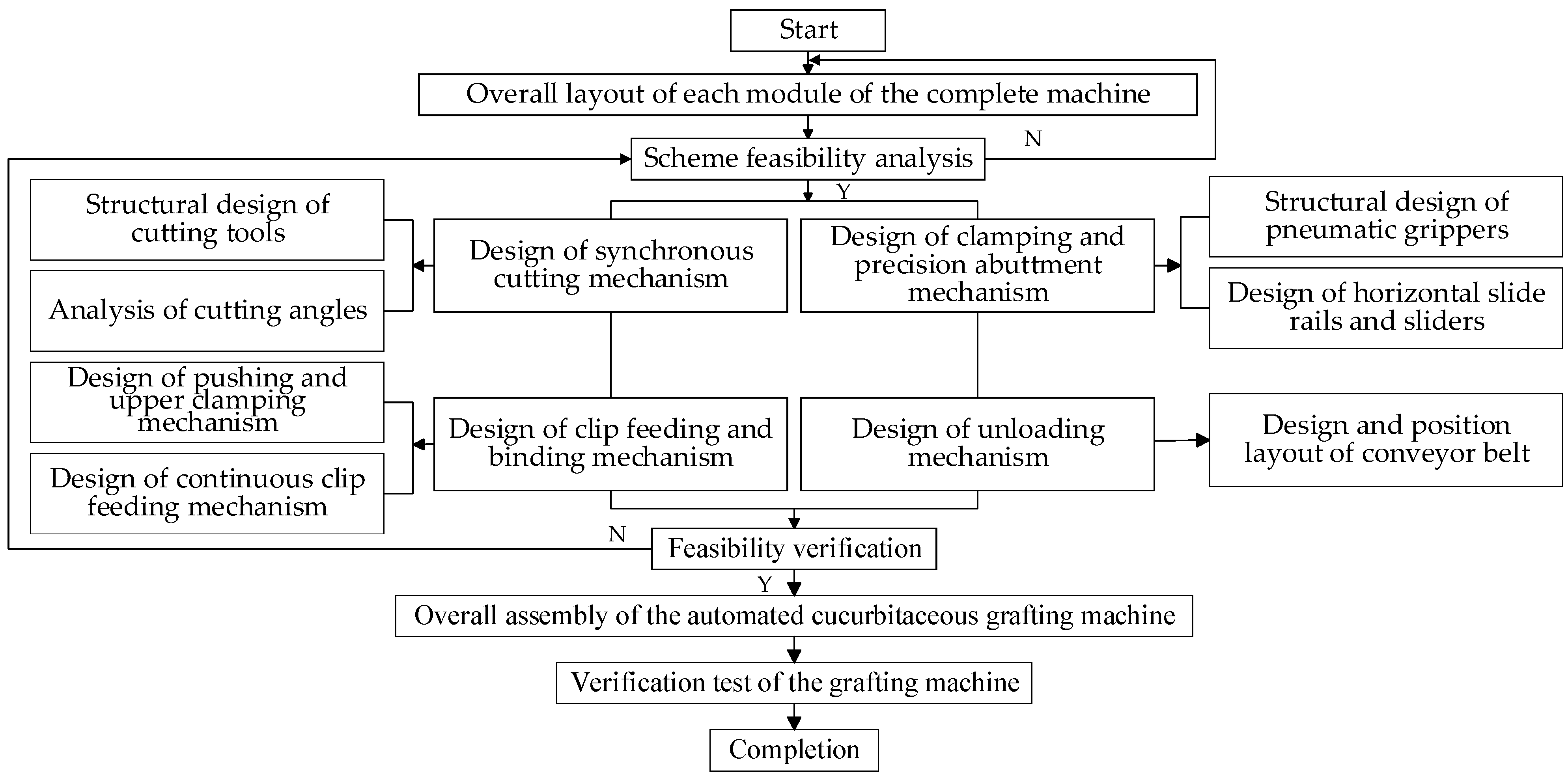
In recent years, China’s protected agriculture has made remarkable progress, yet many seedling nurseries still employ manual grafting methods, resulting in low efficiency. This is particularly true for grafting cucurbit seedlings, a process that is not only complex but also prone to damaging the young plants. To address these practical challenges, relevant personnel have developed automated grafting equipment [33,34]. Table 1 illustrates the hourly operating cost comparison between automated cucurbit grafting machines and manual grafting methods. Semi-automated cucurbit grafting machines achieve significant cost reductions through high efficiency and low unit costs, with comprehensive hourly operating costs amounting to merely 30–40% of manual labour costs. Their advantages become even more pronounced with large-scale deployment. For bases that graft over one million plants annually, the equipment investment can be recouped within one to two production seasons. Consequently, the development of automated cucurbit grafting machines is of particular importance. To achieve the objective of automated operation for cucurbitaceous vegetable grafting equipment, the overall structure of this apparatus incorporates several key functional modules. These specifically include separate positioning of rootstock and scion seedlings, clamping and synchronised cutting mechanisms, precision bonding mechanism, automatic clip feeding system, and conveyance system for the finished grafted seedlings. Centred around these functional requirements, the R&D team completed the comprehensive planning for the grafting machine. Its three-dimensional model and overall design layout are depicted in Figure 1. The research process and key research techniques are illustrated in Figure 2.
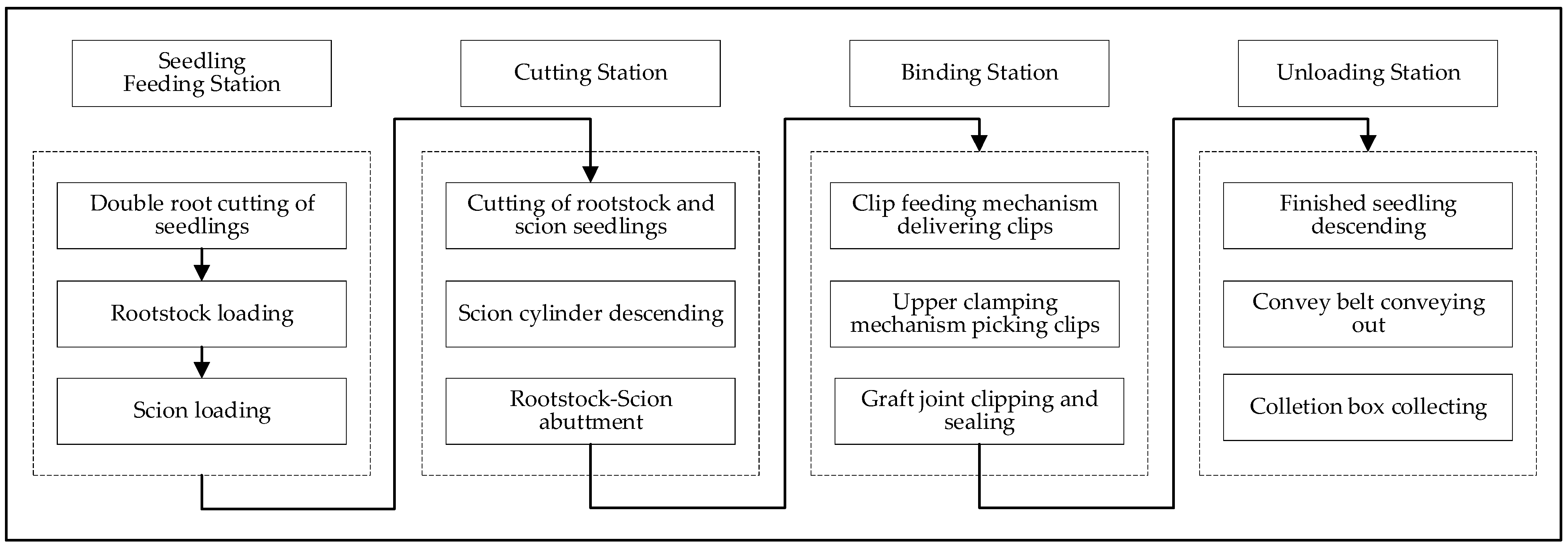
This grafting machine comprises a frame, upon which a rotary motor is mounted. Four sets of cutting and grafting components are evenly distributed between two turntables on the motor’s output shaft. These four sets sequentially correspond to the feeding station, cutting station, binding station, and unloading station in accordance with the rotational direction of the motor’s output shaft. The feeding station secures rootstocks and scions onto the grafting machine. The cutting station performs the cutting of rootstocks and scions. The binding station bonds the cut rootstocks and scions together and secures them using a clamping grafting clip. The unloading station places the grafted seedlings onto the conveyor belt below. This apparatus achieves multi-station assembly line operation by arranging horizontal rotary shafts on the frame and deploying four workstations on these shafts, which continuously rotate in the same direction at intermittent intervals. This facilitates dual-operator control and automated conveyance of finished products, thereby enhancing grafting efficiency. The specific workflow is illustrated in Figure 3.

2.2. Design of the Cutting Mechanism Structure

The current melon seedling cutting apparatus exhibits significant shortcomings in practical operation: residual portions of the rootstock’s growing point and cotyledons are not thoroughly removed, and the fit between the rootstock and scion’s cut surfaces is suboptimal. These factors collectively reduce the survival rate of grafted seedlings. Given the morphological differences between the stems of melon rootstocks and scions, the stability of the grafted union hinges upon achieving precise matching of cutting angles. Grafting interface fit is directly determined by the quality of cutting operations, which is the key to ensuring grafting success [29,34]. This section will determine the optimal cutting angle between the rootstock and the cutting head by analysing the morphological characteristics of the rootstock, and conduct an in-depth study of the cutting principle of the rootstock and cutting head. This will enable the optimisation of the working parameters of the cutting apparatus.

2.2.1. Theoretical Analysis of Cutting Operations

Research into cutting principles is fundamental to ensuring standardized seedling incision formation and constitutes a prerequisite for achieving high-precision grafting. It offers theoretical foundations for the structural design and parameter calibration of cutting apparatuses. The cutting process for cucurbit rootstocks presents considerable difficulty, as it necessitates avoiding exposure of the pith cavity. Consequently, a thorough understanding of structural details of rootstocks is required to define the precise scope of the cutting operation. The cotyledons of rootstocks comprise petioles and blades. During cutting operations, the naturally occurring petioles and blades of cotyledons may interfere with the cutting path of the tool, leading to damage to the cotyledons and adversely affecting the healing of grafted seedlings. To address this, a rootstock separation device must be designed to facilitate cotyledon separation during cutting. This ensures that the cotyledons to be retained are diverted from the cutting trajectory, thereby enhancing the precision and stability of the cutting operation. The analysis of rootstock cutting operations is illustrated in Figure 4.

2.2.2. Selection of Cutting Angles

Currently, both domestic and international grafting equipment predominantly employs the cleft grafting technique. This method requires removing the rootstock’s single cotyledon and growing point, followed by making a cut within the designated area. Simultaneously, the hypocotyl of the scion is severed to form a cross-section structure matching that of the rootstock cut. Finally, the joined rootstock and scion cuts are secured using grafting clamps. The rootstock cutting process requires the following:
(1)
To prevent damage to the rootstock’s cotyledons during cutting and ensure complete removal of the growing point, an oblique cut must be made using the point immediately left of the growing point and the right edge of the stem as reference points.
(2)
During the cutting of the rootstock, caution should be exercised to prevent exposing the pith cavity. Should the pith cavity be incised, the rootstock and scion cuts will fail to fit closely, resulting in grafting failure. The scion seedling will then sprout new roots that penetrate the rootstock’s pith cavity and extend into the soil, thereby inviting disease infection. Consequently, the angle of the knife cut must be precisely controlled.
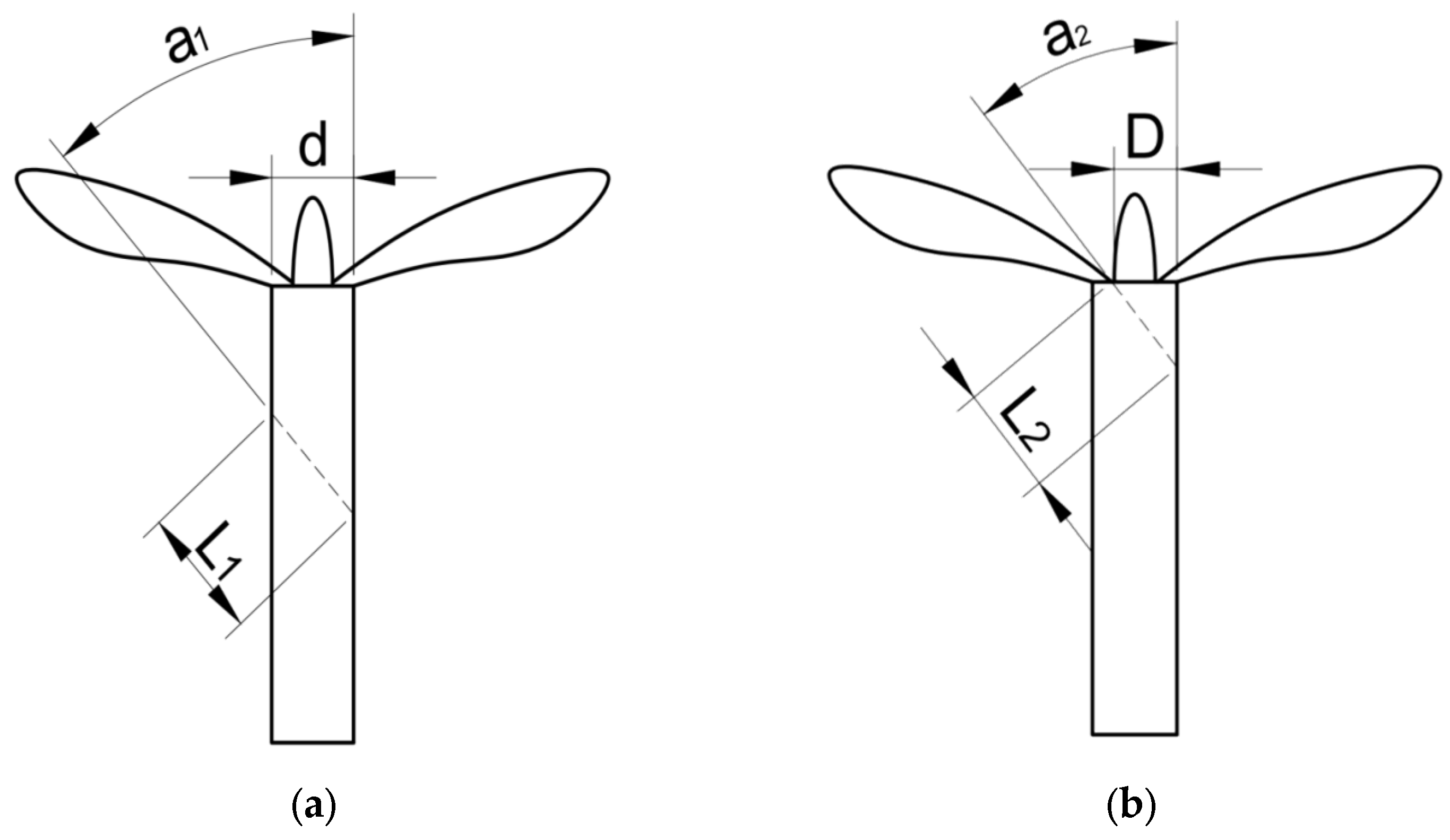
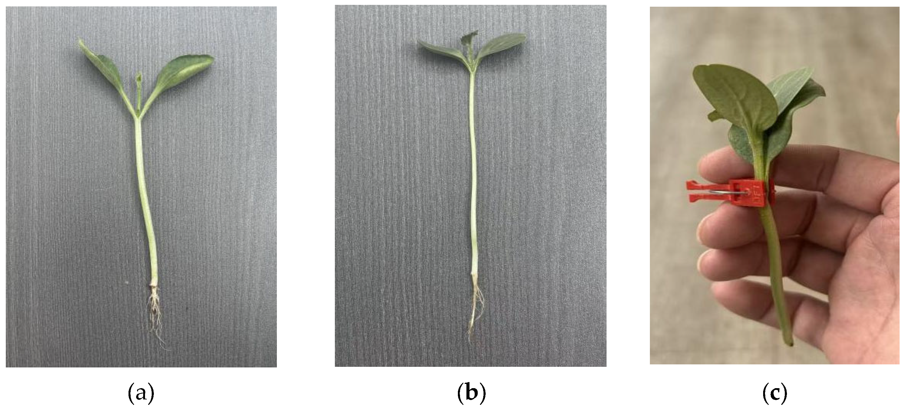
When preparing rootstock cuttings, remove the growing tip and one cotyledon, as shown in Figure 5b. For scion cuttings, make a wedge-shaped cut 10–15 mm above the hypocotyl stem, as illustrated in Figure 5a. The angle α2 formed by the slant cut on the rootstock and the angle a1 formed by the grafting cut both refer to the angle formed between the cut surface and the perpendicular direction. Their typical range is between 20° and 45°. Although a smaller angle increases the cut surface area, it results in insufficient thickness of the cut surface. This weakens the compressive strength of the grafting cut, leading to damage to the scion during the clamping and securing process of grafted seedlings. The stem morphology of rootstock and scion seedlings differs; if identical cutting angles are employed, the scion’s cut surface will be shorter than that of the rootstock. Consequently, the length of the rootstock and scion cut surfaces plays a crucial role in ensuring precise alignment during grafting [35]. The following formula was derived through theoretical analysis of the cutting process:
Length of the scion’s angled cut:
L 1 = d sin α 1
Length of the angled cut on the rootstock:
L 2 = D sin α 2
As both the rootstock and scion cut surfaces are approximately elliptical, their mating surfaces are also relatively complex, making calculations difficult and imprecise. To simplify the cut surfaces, the mating efficiency of the rootstock and scion surfaces is expressed as the ratio of the scion’s cut surface length to the rootstock’s cut surface length, serving as an indicator of cutting quality. Given that the stem tissues of cucurbit seedlings are tender and brittle, and the cutting process involves rapid rigid cutting, the elastic effect or deformation is minimal (typically controlled within 0.1 mm). Its influence on the cut surface length is far smaller than the measurement error and design allowable tolerance; thus, the elastic effect or deformation of plant tissues is neglected.
Cut surface fit rate is expressed as
H = L 1 L 2 × 100 %
Within the formula, H is a percentage representing the major axis length of the cutting surfaces for rootstock and scion, (%); L 1 is major axis length of the scion’s cut surface, mm; L 2 is major axis length of the rootstock’s cut surface, mm; D is distance from the rootstock’s left growth point to the right side of its stem, mm; d is Scion’s short axis diameter, mm; α 1 is scion cutting angle, mm; α 2 is rootstock cutting angle, mm.
Based on the results of prior experiments on the geometric parameters of grafted seedlings’ morphological characteristics, this study takes the grafting of Yongzhen No. 2 pumpkin as the rootstock and Yongtian No. 5 melon as the scion as an example. When the dimensional variation between rootstock E and scion d is minor, the length of the cut surface can be controlled by modifying the cutting angle. The more similar the cut lengths of the rootstock and scion, the greater the contact area between them, thereby promoting the survival of grafted seedlings. To analyse the compatibility between rootstock and scion cutting angles, this study conducted a computational analysis of cut surface length. Experiments were conducted with cutting tool inclination angles set at five levels: 20°, 25°, 30°, 35°, and 40°. The organized experimental data are presented in Table 2.
In accordance with the technical specifications for grafting cucurbitaceous vegetables, to ensure the post-graft survival rate of seedlings, the cutting quality of the interface between the rootstock and scion must be strictly controlled. The cutting angle should be maintained within the range of 20° to 45°, and the effective contact length of the angled cut surfaces must not be less than 6 mm. The stem diameter tolerance range for cucurbit grafting machines is centered on ±0.5 mm (scion: 2.0–5.0 ± 0.3–0.5 mm; rootstock: 4.0–7.0 ± 0.5–0.8 mm), covering over 95% of the natural diameter variation in cucurbit seedlings [36]. Analysis of Table 1 data reveals that the length of the oblique cut surface diminishes progressively with increasing cutting angle: both rootstock and scion cut surfaces attain maximum length at an angle of 20°. Although this angle maximizes the contact area between the two surfaces, an excessively small cutting angle renders the cut surface structure fragile, making it susceptible to compression damage under subsequent pressure from the grafting clamp. Concurrently, significant variations in cut surface length exacerbate misalignment between the rootstock and scion interfaces, increasing exposed areas and thereby adversely affecting grafting outcomes. Should the cutting angle exceed 35°, both the rootstock and scion cut surfaces will measure less than 5 mm in length. Such short surfaces are detrimental to healing and grafted seedling survival. Following comprehensive analysis, it is recommended that the cutting angle be controlled within the range of 25° to 35°. Within this range, the length of the beveled cut surfaces will meet the relevant standards for grafting techniques. Using the aforementioned formula for calculating the bonding rate, when the scion cutting angle is set to 25°, the cut surface length is 6.29 ± 0.14 mm; when the rootstock cutting angle is set to 30°, the bevel length is 6.34 ± 0.18 mm. At these angles, the grafting success rate reached a maximum of 99.2%, meeting both design and process specifications. These data shall serve as the basis for the design and calibration of the cutting equipment in subsequent work.

2.2.3. Cutting Mechanism Structural Design

To mitigate the impact of scion cutting precision on grafting misalignment, this study developed a dual-blade synchronous cutting apparatus. This comprises a positioning frame, a scion cutting assembly situated at the upper right corner of the frame, a rootstock cutting assembly situated at the upper left corner, and a reciprocating motion assembly situated at the lower left corner, as illustrated in Figure 6. By installing rootstock and scion cutting assemblies on either side of the positioning frame, the blades simultaneously cut both rootstock and scion stems. Subsequently, a pneumatic cylinder pulls the scion towards the rootstock for grafting. This addresses the existing issues of uneven cuts on rootstock and scion, along with discrepancies in their interfacial fit, which previously resulted in low grafting success rates.
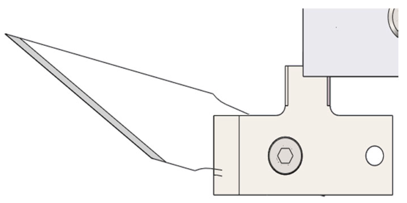
The cutting tools for rootstocks and scions comprise a blade holder, blade shaft, indexing pin, and cutting blade. The grafting tool features a replaceable blade assembly, comprising a blade holder and a blade handle. The blade holder is a square tubular body, with the blade handle movably mounted within it. The mounting base has a sliding groove formed on one side, which accommodates an indexing pin via sliding engagement. The base of the indexing pin is engaged with a pin hole. One end face of the blade handle has a fixedly mounted blade shaft, with a blade fitted onto the shaft. To disassemble the tool, simply withdraw the movable section of the indexing pin and rotate it 90 degrees. This allows the tool holder and mounting base to be detached for replacement, facilitating quick and convenient replacement of grafting tools. The rootstock cutting assembly incorporates a rootstock separation plate, which is a wedge-shaped block. The rootstock is positioned through the rootstock clamp jaws onto the separation plate, with the retained portion placed above the plate and the section to be cut positioned beneath the separation plate. As the cutting blade cuts along the inclined surface of the rootstock separation plate, it precisely removes the stem segment and cotyledons beneath the plate. Consequently, the inclination angle of the tool matches that of the rootstock separation plate, with the cutting blade following the slope of the separation plate to enhance cutting accuracy. Blade grooves are incorporated into the positioning blocks for both rootstock and scion, facilitating smooth blade penetration through the designated cutting area. Inaccurate positioning of these grooves may result in cutting angle deviation, thereby compromising grafting success rates.
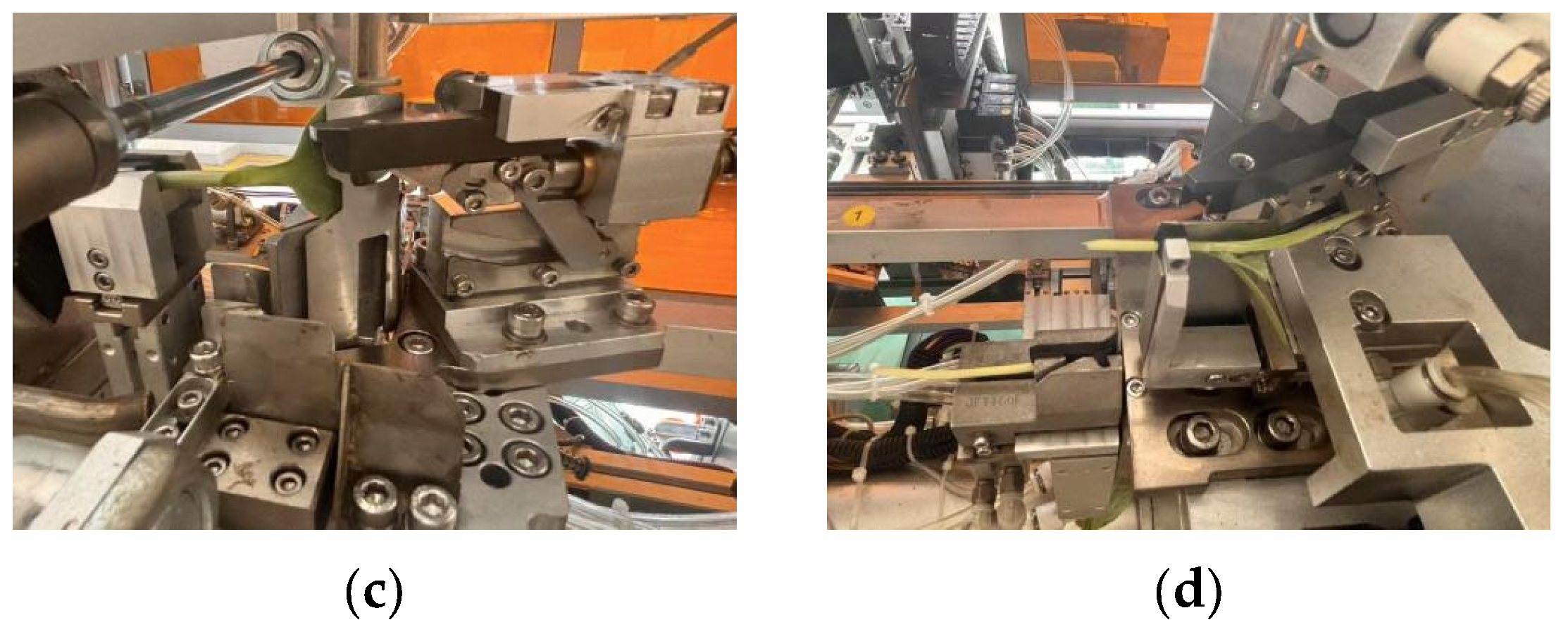
The cutting apparatus is equipped with separate clamping assemblies for the rootstock and scion, each comprising a positioning chuck and jaws. During operation, the jaws are driven by a clamping cylinder to secure the grafting seedlings. Subsequently, the cutting cylinder is actuated to extend the cutting tool, simultaneously cutting both the rootstock and scion stems. The tool then retracts to its original position. The cutting sequence is illustrated in Figure 7: Prior to processing, the rootstock and scion must be clamped into the fixed assembly. At this stage, the rotary cylinder is activated, propelling the secured seedlings into the cutting zone. Subsequently, the drive cylinder for the cutting tool is pressurized, enabling the tool shank to sever the seedling stems. Upon completion of the cutting operation, the clamping jaws securing the upper section of the rootstock and the lower section of the scion are released simultaneously. The severed lower section of the scion and upper section of the rootstock are then discarded into the waste collection device positioned below the assembly.
For cutting young seedlings, the selection of tools and blades is particularly crucial. Should the blades become worn, dull, or corroded, cutting the rootstock and scion may result in fraying or blade slippage. In such instances, the quick-change tool should be removed. The blade mounting structure is illustrated in Figure 8, with detailed specifications as follows:
(1)
Structure: Comprising a blade and a matching blade handle, the rear of the blade features a locking groove that engages precisely with the handle, facilitating swift assembly and disassembly.
(2)
Shape: It has an overall willow-leaf form with a curved cutting edge and an exceptionally sharp tip. The blade tapers narrowly at the front and widens slightly towards the rear, optimizing precision cutting applications.
(3)
Bevel Angle: The cutting edge is honed to an angle of approximately 15–20°. This angle ensures optimal sharpness and facilitates precise incisions.
(4)
Service Life: No specified service life; it is recommended to inspect the blade condition when grafting 2000 seedlings.
(5)
Material: Constructed from high-strength stainless steel, this material balances edge sharpness and hardness while providing excellent corrosion resistance.
During rootstock cutting operations, the seedling stem must be secured via a positioning fixture, while the rootstock separation plate is designed to provide a safe working zone for the cutting tool. This configuration positions the retained rootstock segment above the separation plate, while the excised portion lies beneath it. The cutting tool removes cotyledons through the separation groove at the plate’s front edge. The relative positioning between the rootstock separation plate and cutting tool is illustrated in Figure 9.

2.3. Design of an Integrated Clamping and Bonding Mechanism

2.3.1. Structural Design of the Gripping Claw

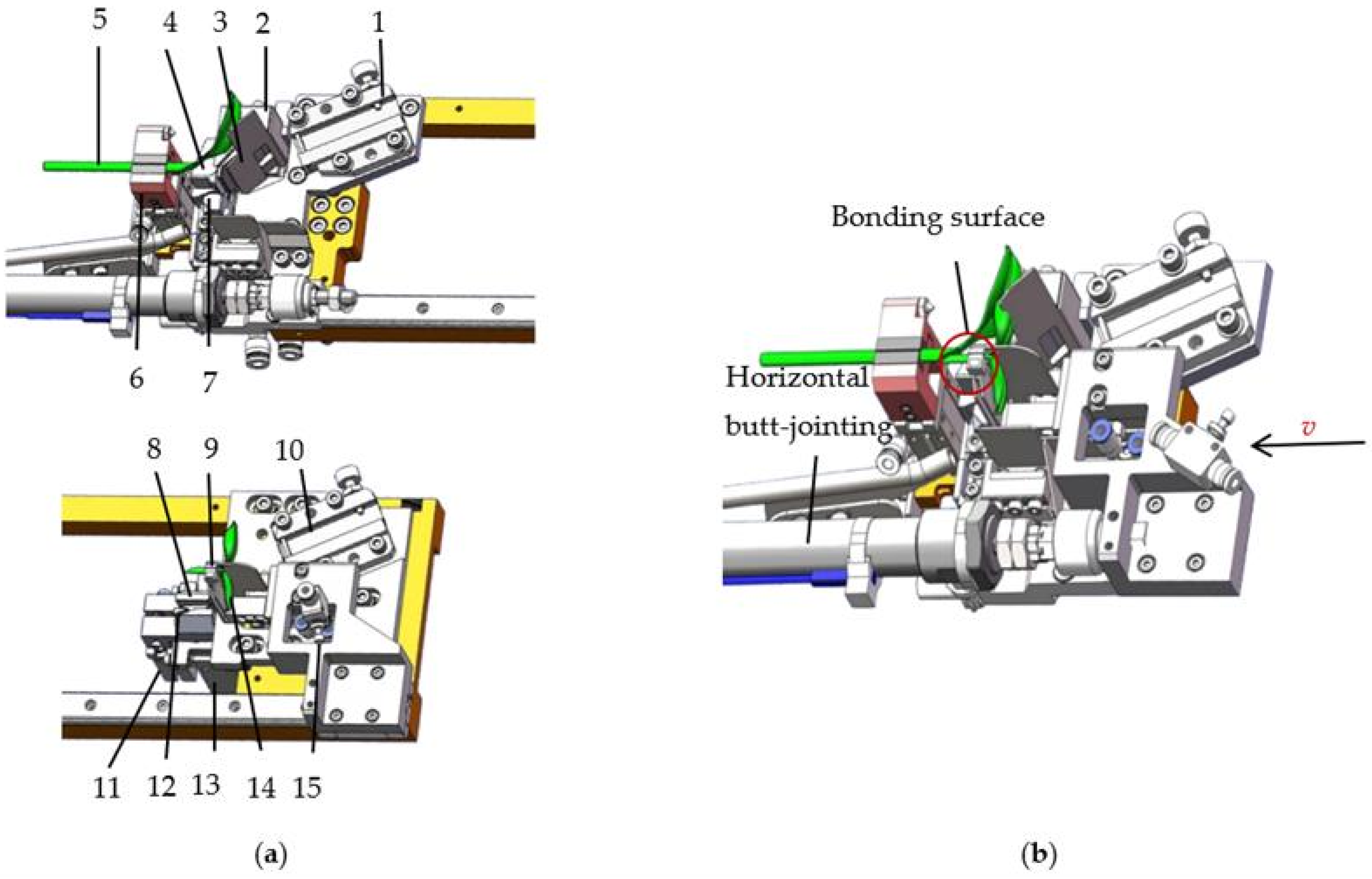
To meet the operational specifications of the four workstations (sequentially: clamping, cutting, bonding, and unloading) for the automated grafting equipment for cucurbit crops in this project, the coordinated gripper for both rootstock and scion is designed in this section, whose structure is illustrated in Figure 10. The rootstock clamping device comprises rootstock clamping jaws, rootstock finger cylinders, rootstock positioning blocks, and tool positioning blocks. The rootstock finger cylinders, rootstock positioning blocks, and tool positioning blocks are all fixed to the positioning frame. The output end of the rootstock finger cylinder connects to the rootstock clamping jaws. The rootstock finger cylinder controls the opening and closing of the clamping jaws to secure and release the rootstock. This effectively prevents axial movement of the rootstock while supporting its stem to counteract gravitational sagging. Such sagging could compromise positioning accuracy and adversely affect grafting success rates. The tool positioning block at the upper right corner of the gripping mechanism features a tool slot on its front face for securing the tool. This slot enables direct snap-fit attachment of the tool, facilitating its repair and replacement. The scion seedling gripping assembly comprises scion clamping jaws, scion finger cylinders, telescopic cylinders, and tool positioning blocks. The output end of the scion finger cylinder connects to the scion clamping jaws. This cylinder controls the opening and closing of the clamping jaws, facilitating the picking and placing of scion seedlings. The output end of the telescopic cylinder is connected to a scion positioning block. Both the scion positioning block and the tool positioning blocks are fixed to the positioning frame. The telescopic cylinder controls the forward and backward movement of the scion positioning block. Upon completion of scion cutting, the telescopic cylinder retracts the scion positioning block, allowing the cut scion to disengage from the scion positioning slot. This design ensures precise alignment accuracy for subsequent grafting of rootstock and scion.
Upon the rotary feed cylinder’s magnetic switch detecting the operator’s insertion of seedlings, the gripping mechanism’s claws execute a clamping action driven by the corresponding cylinder. Subsequently, the rotary cylinder drives the mechanism to rotate, transferring seedlings from the single-seedling tray to the cutting station to accomplish synchronized cutting of rootstock and scion. Upon completion of cutting, the cutting blade automatically resets. The magnetic switch then senses this return position and transmits a signal. The scion clamping jaws, actuated by the telescopic cylinder, retract from the seedling upon receiving the cutting completion signal. This creates operational space for the subsequent lateral leftward movement of the scion during the grafting process.

2.3.2. Design of Grafting Seedling Cleft Grafting Mechanism

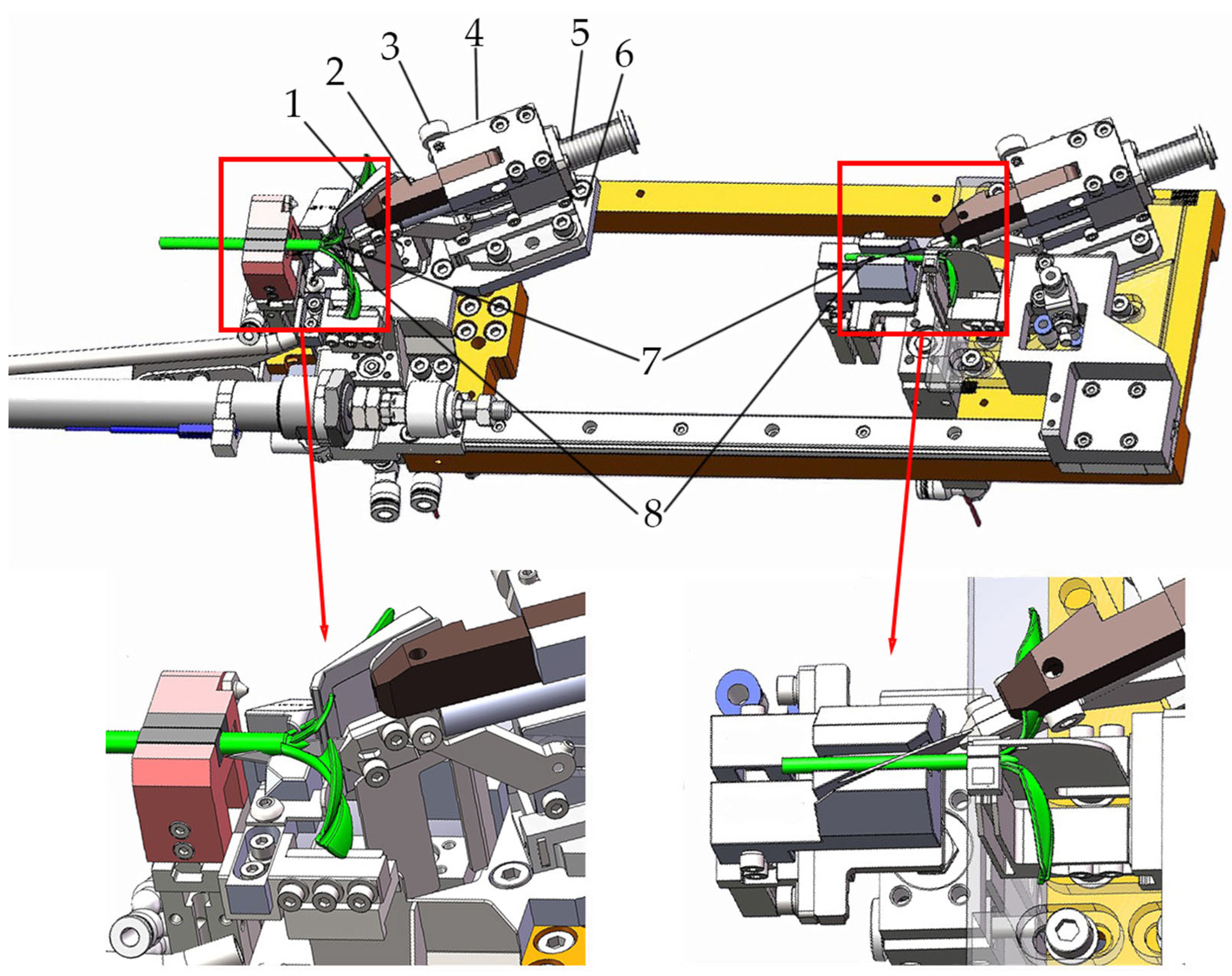
Under the existing technical solutions for clamping and cutting mechanisms, this study has developed a horizontal traverse lifting-type bonding apparatus [37,38]. As illustrated in Figure 10b, the lower frame of this positioning mechanism incorporates horizontal guide rails. Pneumatic components drive the pre-cut scion along these rails to achieve transverse alignment with the rootstock. Since the cutting height and positioning reference points of both rootstock and scion are fully standardized, this standardization ensures no misalignment during the bonding process, thereby enhancing grafting survival rates.
The specific operational sequence is as follows: Upon completion of the seedling cutting process, the cutting blade automatically retracts. At this point, the magnetic sensor on the cutting mechanism detects the blade retraction signal; subsequently, the telescopic cylinder drives both the rootstock clamp and scion clamp to retract synchronously from the seedling, thereby creating clearance for the subsequent lateral movement of the scion during the grafting operation. The retracted clamp positions are illustrated in Figure 10a.
Upon detection by the magnetic sensor on the gripper’s telescopic cylinder that the gripper has completed its retraction maneuver, the bonding process is immediately initiated. At this stage, the single-axis push-rod bonding cylinder is pressurized to drive the upper clamping jaws, causing them to carry the pre-cut scion seedling in a lateral traverse towards the rootstock’s clamping position. This ultimately achieves precise alignment between the scion seedling and rootstock seedling, and the grafting effect is illustrated in Figure 10b. Compared to the operational model of traditional grafting machines, which requires clamping and transferring the grafting materials to a new workstation, this apparatus enables direct grafting at the original workstation immediately after the cutting process. The scion and rootstock are aligned solely through lateral movement of the clamping jaws on the scion. This integrated design effectively prevents angle deviation caused by transfer movements, minimizes unnecessary displacement, and consequently enhances precision control over the grafting interface.

2.4. Design of the Clamping and Strapping Mechanism

After the grafting machine completes synchronized cutting and precise alignment, the rootstock and scion must be securely fastened via an automatic clamping mechanism. The grafting clamp serves as the core component for this critical operation. To ensure the safety and reliability of the grafting process, the clamping force applied by the clamp must remain below the safe stress threshold of the seedlings. Accordingly, this section establishes a three-dimensional model of the grafting clamp and conducts mechanical analysis to develop an automated clamp feeding device. This device primarily comprises two components: continuous clamp feeding module and clamp insertion module.

2.4.1. Study on the Mechanism of Grafting Clips

  • Grafting clamp selection
The grafting clamp is an indispensable component in the grafting process, with its performance having a decisive impact on the growth and development of grafted seedlings. To enhance the survival rate of grafted seedlings, precise control of clamping force is essential. Excessive clamping force may cause tissue damage to the seedlings, while insufficient force may result in loosening and detachment at the graft union between scion and rootstock [39]. Therefore, in grafting seedling production, selecting grafting clamps with suitable clamping force is the core element in ensuring operational quality. Commonly used grafting clamp types in production are shown in Figure 11.
As shown in Figure 11, Grafting Clip No. 1 is injection-molded from PE (polyethylene) rubber-plastic material in a single piece. Its integrated head and tail design offers high flexibility, elasticity, and lightweight properties, preventing damage to the seedling stem during clamping. However, this grafting clip is only suitable for non-cotyledonous grafting of Solanaceae crops, where the rootstock and scion stems are of similar size. It is not applicable for monocotyledonous grafting methods used in cucurbit crops. The No. 2 grafting clamp features a sleeve-type design. Compared to other grafting clamp types, its sleeve structure is more streamlined and naturally sheds as the seedling grows after grafting. However, existing sleeve-type grafting machines in China face issues such as low grafting success rates and complex equipment structure. Both Grafting Clamps No. 3 and No. 4 are commonly used in manual grafting operations in China. Grafting Clamp No. 3 features a narrower jaw opening compared to No. 4, typically used for grafting young seedlings of Solanaceae species. Conversely, Grafting Clamp No. 4 exhibits the opposite characteristics. Both clamps possess larger jaw openings and greater clamping force than other grafting clamps. During automated grafting machine operations, these clamps are prone to damaging young grafted seedlings and are therefore not utilized in such processes. Grafting Clamp No. 5 is the most commonly utilized steel ring spring clamp in domestic grafting equipment, featuring a split design for its jaws and tail. This clamp is inexpensive and simple in construction, with clamping force regulated by the steel ring spring. Its jaws operate in a non-enclosed opening-closing configuration. It demonstrates good adaptability in monocotyledonous grafting operations for cucurbitaceous vegetables. After comprehensive evaluation, the grafting clamp selected in this study is the domestically specialized No. 5 grafting clamp. For a straightforward comparison, the specifications and parameters of each clamp are compared as shown in Table 3.
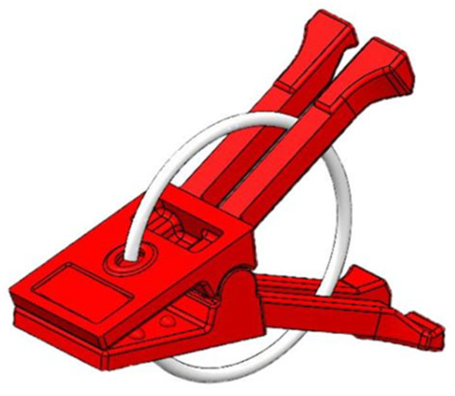
To understand the structural characteristics of Grafting Clip No. 5, A 3D model of the grafting clip was developed via Solidworks 2021 3D modelling software, as illustrated in Figure 12.
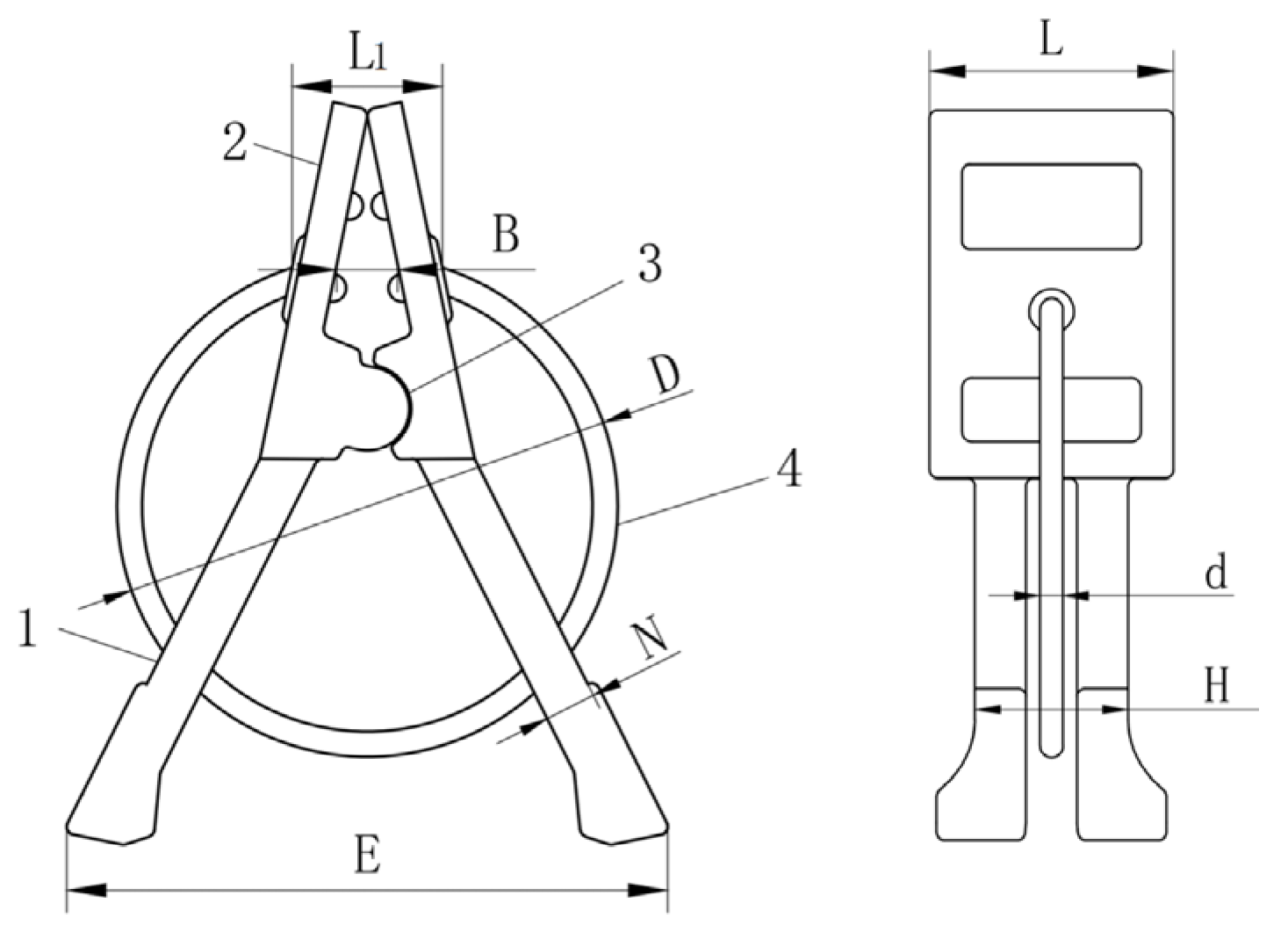
To obtain the geometric parameters of Grafting Clip No. 5, as illustrated in Figure 13, this clip comprises two components: a plastic body and a spring ring. The body is injection-molded as a single piece, while the spring ring is a circular steel band with two openings. These openings engage with fixed positions on the outer surfaces of the body’s jaws. By applying a predetermined preload to the jaws, the body and spring ring form an integral structure.
The grafting clamp operates as follows: Upon the upper clamping mechanism applying specific pressure to the rear of the clamp body, the jaws overcome the resistance of the spring coil to open; subsequently, the upper clamping mechanism advances, positioning the grafting clamp against the contact surfaces of the scion and rootstock incisions; Upon cylinder retraction, pressure at the clamp body’s rear is released, allowing the jaws to clamp the grafted section under spring coil rebound force, thereby securing the grafted seedling. In practical seedling production, grafting failures due to the inappropriate selection of grafting clamps are relatively common. Consequently, research into the grafting clamp clamping force properties holds significant value for enhancing the graft seedling survival ratio. Table 4 presents the measured data for various parameters of the grafting clamps, providing a foundational reference for their mechanical analysis.
2.
Safety validation of grafting clamps
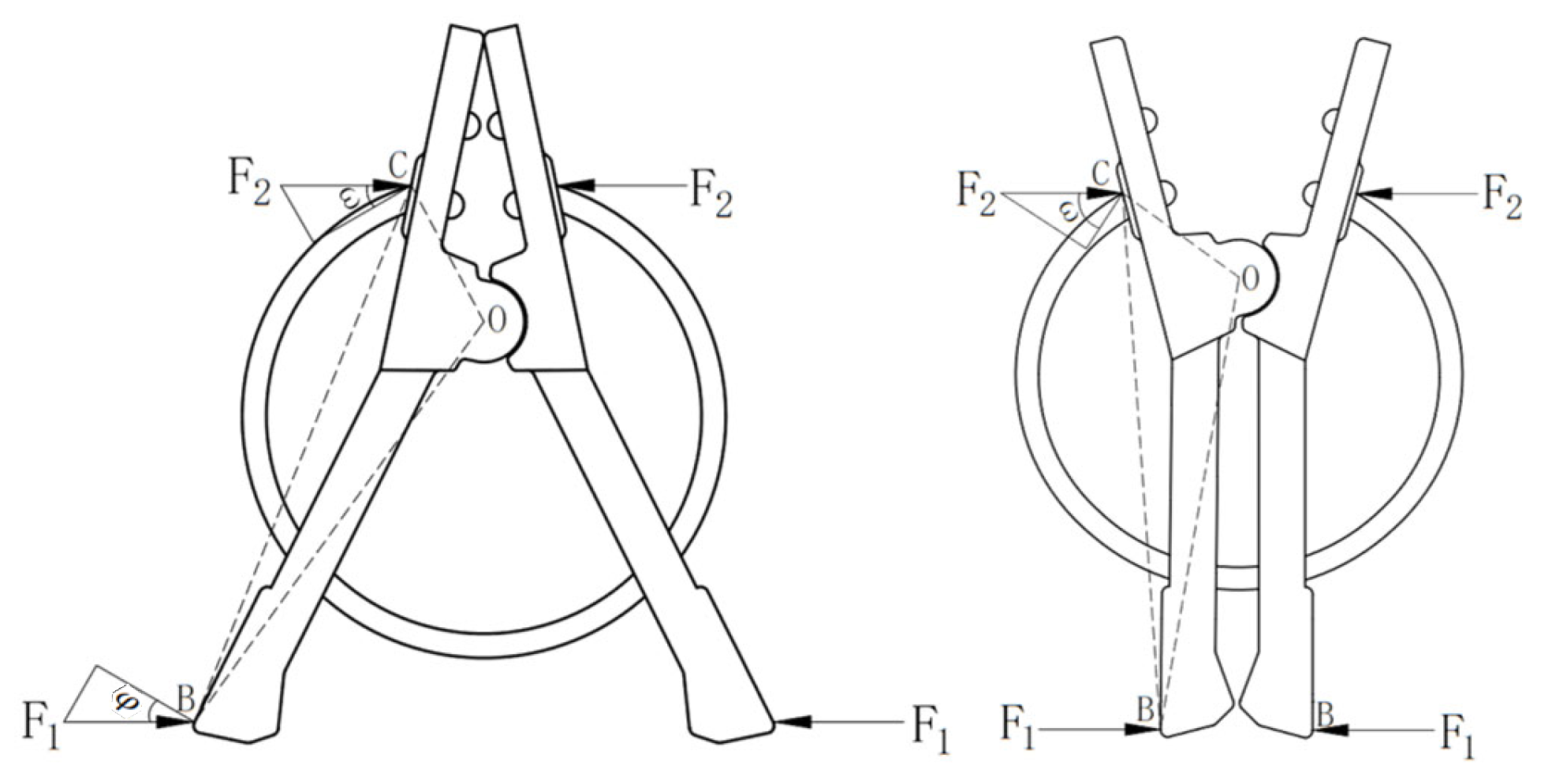
The clamp body of the grafting clamp comprises an integral structure formed by the jaws and handle, with its left and right sides functioning equivalently as lever arms. Assuming no deformation occurs when compressive force is applied to the handle, upon pressure being applied to the rear end of the handle, both jaws will open laterally with the central point as the fulcrum. The tension in the jaws increases progressively with the magnitude of compression. When analysing a single side of the clamp body, the pressure exerted on the handle and the resistance from the steel ring establish a state of torque equilibrium at the central point of the clamp body. When no pressure load is applied to the rear end of the clamp handle, the compression displacement is minimal; conversely, when the rear end of the clamp handle is in a parallel position, the required pressure load reaches its maximum value, at which point the displacement is also maximal. The stress conditions within the clamp body are illustrated in Figure 14. Based on the rootstock and scion test data from Chapter 2, the stem thicknesses for the rootstock and scion measure 3.6 mm and 2.7 mm, respectively. Therefore, investigating the clamping force exerted on the stem at the maximum opening state of the grafting clamp and comparing it with the maximum clamping force of cucurbit rootstock seedlings is an effective approach. This approach can effectively ensure grafted seedling survival rate under secure clamping conditions.
According to the stress analysis diagram of the grafting clamp, the compression torque equilibrium equation for the rear section of the clamp body is:
F 1 cos φ l O B = F 2 cos ω l O C
Simplified to:
      F 1 = F 2 cos ω l O C F 1 cos φ l O B
In the formula, F 1 is pressure exerted on the rear section of the clamp body, N; F 2 is Spring resistance, N; ω is The angle between force F 2 and the direction perpendicular to lever arm l O C , N; φ is The angle between the force F 1 and the lever arm l O B in the perpendicular direction, N; l O C is Length of the lever arm from force F 2 to the centre point, mm; l O B is Length of the lever arm from force F 1 to the fulcrum, mm;
The values l O C , l O B , φ and ω are calculated from the geometric three-dimensional model, The F 1 value was obtained through mechanical compression testing of the clamping body.
The mechanical characteristics of graft clamps were determined using an electronic universal testing machine, employing domestically manufactured specialized grafting clamps as test specimens. A total of 30 compression specimens were tested. During testing, the clamp handle was positioned between the compression head and compression support. Under computer control, the compression head was lowered until it just touched one end of the clamp handle. After completing data reset, the test was initiated [40]. In this test, the specimen was subjected to compressive loading at a loading rate of 0.2 mm/s. As the pressure exerted by the compression head increased, the jaws of the grafting clamp gradually opened until loading ceased once the clamp body was compressed to a state where both handles were parallel. Relevant data were measured and recorded synchronously. Following the test, computer-generated curves depicting the relationship between compressive displacement and the forces exerted on the jaw handles and jaws were extracted. Processing the compression test data yielded a curve illustrating the variation in compressive force with displacement. The specific test procedure and data curves are illustrated in Figure 15.
The compressive load–displacement curve at the rear of the clamp body shows that when displacement stays within the 0.8 mm range, the rate of load increase accelerates markedly. Actuating the clamp handle necessitates overcoming two resistive factors: the resistance exerted by the spring steel ring and the material’s inherent initial tension. When displacement falls between 0.8 mm and 14 mm, the load exhibits a steady increase, during which the short spring steel ring progressively releases pressure. Beyond 14 mm displacement, the load rises continuously once more before stabilizing. This indicates that the compressive load has now surpassed the spring’s maximum resistance, with the clamp handle compressed into a flush position, achieving its maximum compressive force value.
A mechanical analysis of the compressive elastic limit of grafted seedlings in the Cucurbitaceae family has been conducted in the preliminary stage. Suitable test subjects were selected, and 20 seedlings per group were prepared. After processing the compressive test data, the experimentally measured values were calculated using Equation (5). The results were then compared with the elastic limit of the grafted seedlings, yielding the conclusions presented in Table 5.
Analyzing the Data in Table 5 reveals that the values recorded for grafting clamps when clamping force reached its maximum did not exceed clamping force elastic threshold that grafted seedlings could withstand. Consequently, grafting clamps exhibit no seedling damage during actual clamping procedures. They fully meet the clamping requirements for grafted seedlings of cucurbit species, offering high safety and reliability.

2.4.2. Continuous Clamp Feeding Mechanism

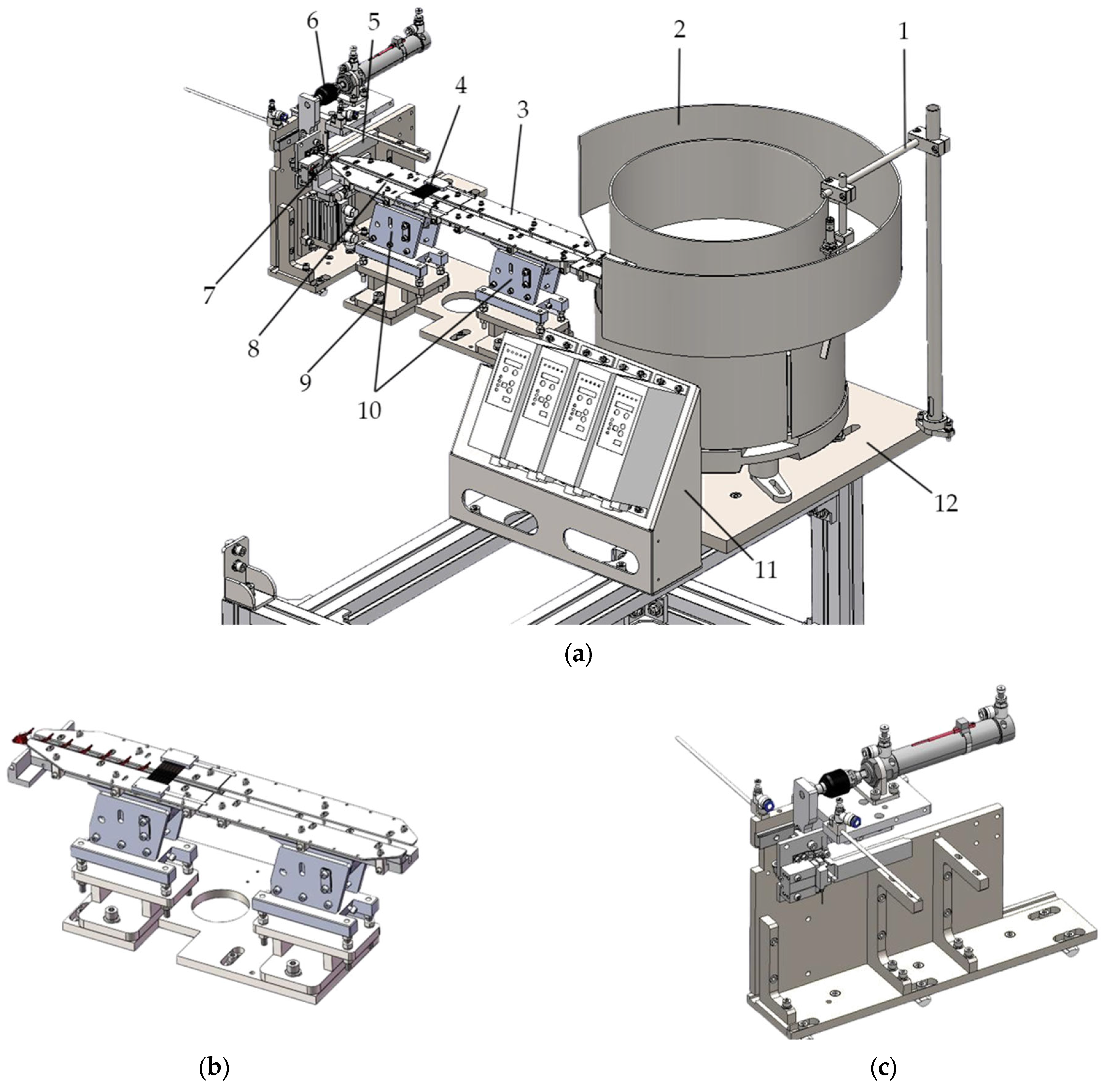
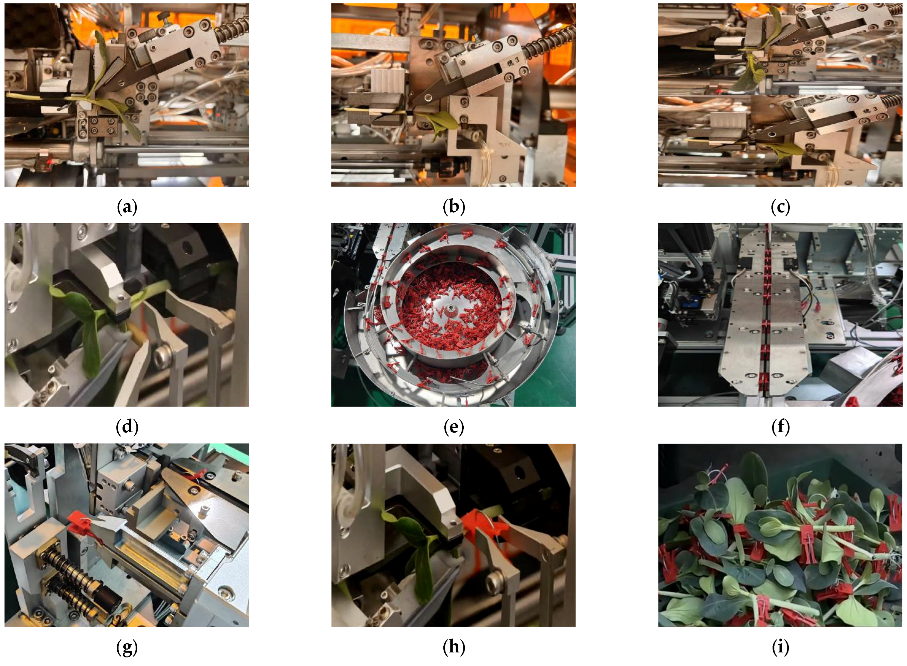
The majority of domestic grafting equipment employs a disc-type vibratory collet feeder, which utilises pulsed vibration to drive collets within the vibratory tray along a helical ascending track. This mechanism represents the most widely adopted feeding system globally, delivering grafting clamps to designated positions with consistent speed and reliability. However, when the consumption rate of grafting clamps within the grafting machine falls below the feeding rate from the vibrating feeder, the feeder outlet continuously supplies grafting clamps to the linear feeder. This results in reduced spacing between grafting clamps on the linear feeder, potentially causing jamming issues [41]. To address the aforementioned issues, this project has designed a linear feeder for preventing jamming in vibratory feeders, as illustrated in Figure 16a. Through the operation of a two-stage linear feeding mechanism, when the gap between adjacent clamps near the feed outlet falls below the normal value, the vibrating feeder and linear feeder can be temporarily shut down and restarted to ensure smooth clamp feeding. Additionally, photoelectric distance sensors monitor the gap between adjacent clamps, enabling automatic control of the start/stop functions of the vibrating feeder and linear feeders, thereby regulating feed rate to maintain uninterrupted clamp supply. This achieves continuous, stable feeding performance, resolving the aforementioned issue of material jamming caused by insufficient clearance.
This vibratory feeder linear feeding mechanism comprises a vibrating feeder tray, linear feeders, and a grafting clamp separation mechanism. The linear feeders consist of two-stage linear feeding units, with the ends of each adjacent unit connected in a head-to-tail configuration, as shown in Figure 16b. The feeding outlet of the vibrating feeder tray is connected to the linear feeder unit positioned at the front end of the linear feeders. Each linear feeder unit is fitted with a vibrating feeder at its base. Each vibratory feeder is electrically connected to a switch controller for regulating its operational state. The switching states of the first-stage and second-stage linear feeders can be controlled via a first switch controller and a second switch controller, respectively. A mounting base is fixedly installed at the bottom of the vibrating feeder, with grafting clamps uniformly arranged along the linear feeding mechanism. Should the gap between any two adjacent grafting clamps on the linear feeding mechanism near the feed inlet begin to fall below the normal value, the vibrating feeder and linear feeding mechanism may be temporarily shut down and then restarted to ensure uninterrupted feeding of the grafting clamps.
Furthermore, an optical distance sensor is fixedly mounted on the upper surface of the linear feeder. This sensor is electrically connected to a microprocessor, which in turn is electrically connected to a switch controller. The optical distance sensor determines the gap size between two adjacent grafting clamps by measuring the time required for a clamp to pass through its detection point. For instance, when the feeding rate is at normal speed, the time required for the grafting clamp to pass the optical distance sensor falls within a specified range. Should the duration each time the sensor is obstructed exceed this prescribed range, it indicates that the consumption rate of grafting clamps within the grafting machine is lower than the feeding rate from the vibrating feeder. This consequently prolongs the time required for the grafting clamp to pass through this specific point. At this point, the microprocessor issues a shutdown command to the switch controller, thereby halting the vibrating feeder.
Prior to feeding the clamps, a large quantity of disorganized grafting clamps is first poured into the vibrating feeder. During the feeder’s vibration, the clamps align themselves and slowly progress towards the feeder’s outlet. Simultaneously, they move forward in an orderly fashion along the feeder’s chute. During feeding, the single-rod feeding cylinder activates, propelling the clamp box forward. This action pushes the grafting clamps into the box’s slots, completing a single separation cycle. The reciprocating motion of the single-rod feeding cylinder advances the clamps along the vibrating tray’s slide during each stroke. This mechanism enables rapid separation of individual clamps, enhancing feeding efficiency and operational stability.

2.4.3. Push-Up Clamping Mechanism

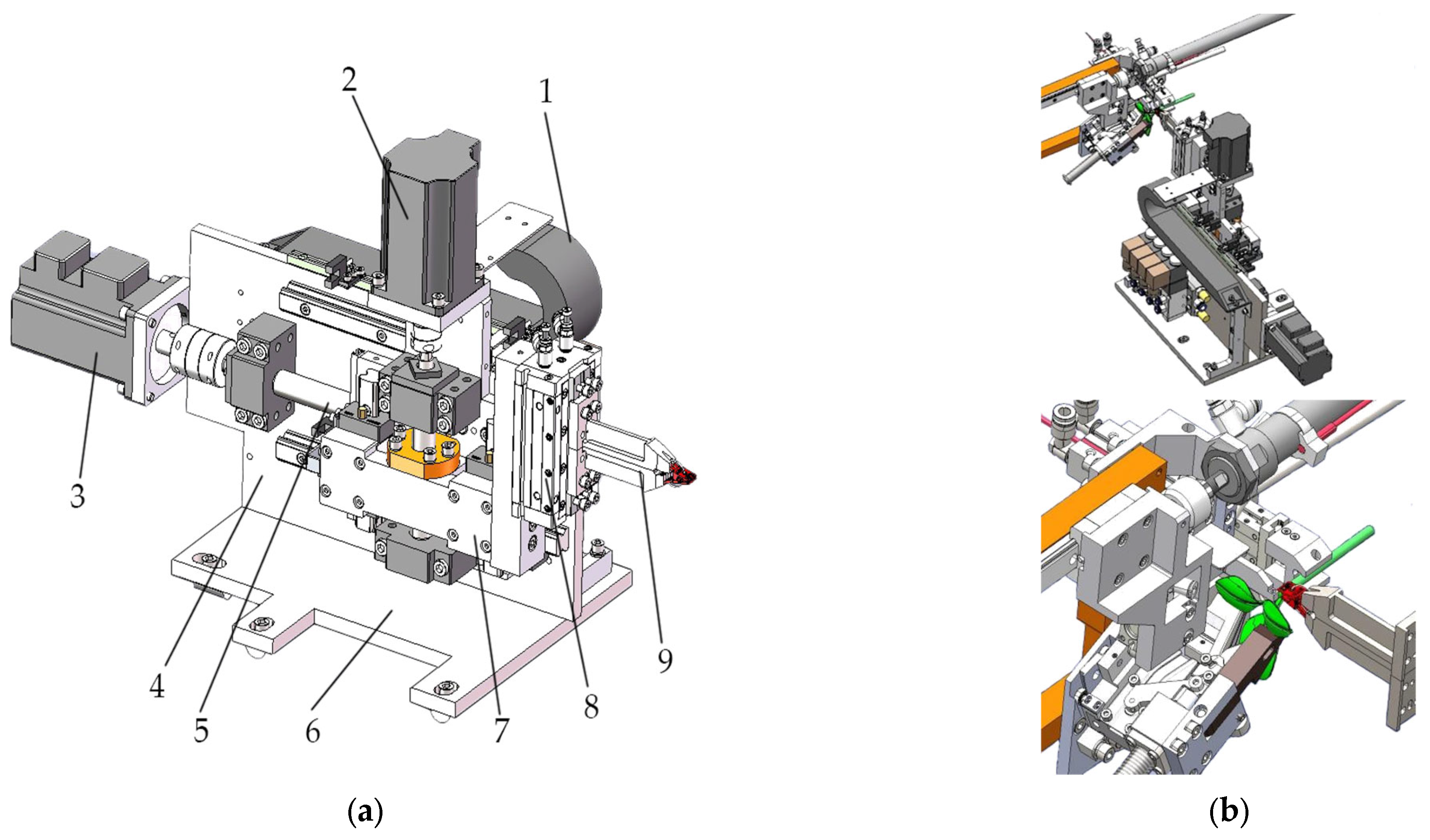
Figure 17 depicts the structural configuration of the clamp pusher mechanism. Its core components comprise the grafting clamp jaws, the cylinder driving the jaws, the lifting motor and guide rails for height adjustment, and the feed motor and slide rails responsible for horizontal pushing. Upon delivery of the clamp to the retrieval point by the clamp supply mechanism, the lifting motor and feed motor coordinate to position the jaws at the retrieval point. At this stage, the first limit switch is activated, triggering the system to receive the signal. The pneumatic cylinder then drives the jaws to close, gripping the tail end of the grafting clamp. Subsequently, the telescopic cylinder of the clamp delivery unit retracts while the feed motor continues propelling the gripper and grafting clamp forward. Upon reaching the securing position for the pre-aligned grafting shoot, the second limit switch is activated. Upon receiving this signal, the pneumatic cylinder drives the gripper to open, allowing the grafting clamp to securely bind the grafting shoot. This completes the clamping operation for the grafting shoot.

3. Results

3.1. Results of Experiments

3.1.1. Evaluation of Automated Grafting Machinery for Cucurbit Seedling Propagation

Focused on designing and developing core grafting components for the grafting machine, the team has completed the manufacture of an automated cutting mechanism, alignment device, and clamping system for cucurbit crops. During collaborative research, the team worked alongside other technicians to advance the prototype testing and assembly of the cucurbit automatic grafting equipment. To validate performance, the project group assessed task completion rates for each component across core processes, including stock and scion feeding, clamping, cutting, alignment, and clamp wrapping. The project group also evaluated the overall grafting success rate through comprehensive data analysis.
The success of grafting operations hinges upon ensuring seedlings sequentially pass through four stages: loading, cutting, alignment, and clamping. Consequently, critical factors influencing grafting efficacy include rootstock loading, scion loading, removal of rootstock growth points, scion stem cutting, cut surface alignment, and automatic clamping. Overall grafting success rate is determined by multiplying the success rates of each individual stage. The criteria for successful cutting primarily rely on whether rootstock and scion cut lengths meet the precision requirements for surface alignment. Equipment productivity is measured by timing the entire grafting process from the first to the last plant. By computing the count of successful plants and the duration required, this is converted into the equipment’s operational efficiency per unit time.
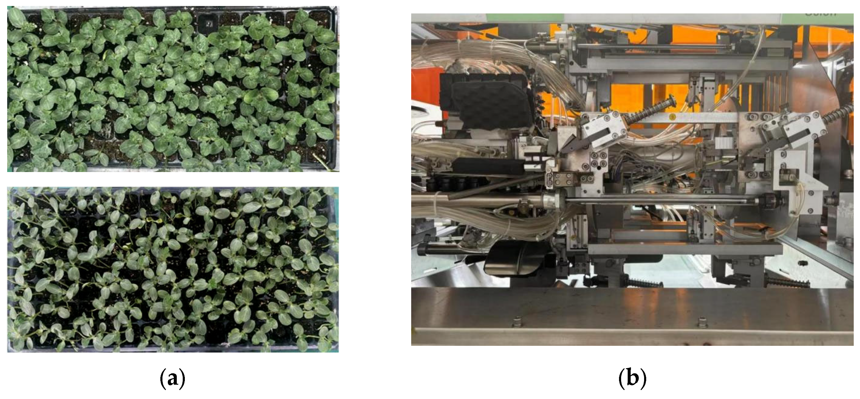
This trial employed Yongzhen No. 2 pumpkin as rootstock seedlings and Yongtian No. 5 melon as scion seedlings for grafting combinations. After cultivating both types of seedlings to an age suitable for mechanized grafting, the trial proceeded in two phases: the first phase involved cutting performance testing, comprising five parallel trials, each using 50 white-seeded pumpkin seedlings and 50 melon seedlings. Rootstock and scion cut geometric parameters were measured to assess the surface contact rate. The second phase focused on verifying grafting success rates and production efficiency, again employing five parallel trials. The sample size for each trial was increased to 100 plants each of white-seeded pumpkin seedlings and melon seedlings. Grafting operations were performed using the prototype lap-grafting equipment developed for this study, as illustrated in Figure 18.
To minimise the risk of cross-contamination, the following cleaning procedures must be observed during trials:
(1)
Prior to operation: Wipe cutting blades, locating jaws, and other relevant components with 75% alcohol. Clean equipment casings using chlorine-based disinfectant.
(2)
During operation: Wipe blades and fixtures with alcohol swabs every two hours. Promptly remove seedling juices and residues to prevent bacterial proliferation due to accumulation.
(3)
After operation: Dismantle removable components (e.g., fixtures, blades). Rinse with clean water, then soak in disinfectant for 15 min before rinsing with clean water and air-drying. Clean internal equipment with a high-pressure air gun to remove dust. Apply sterile lubricant to transmission components.

3.1.2. A Study on Cutting Parameter Evaluation for Successful Grafting of Cucurbit Seedling

Based on prior research into cutting mechanisms and vegetable grafting process specifications, the cutting angle for scions was set at 25° and for rootstocks at 30° during the trial. Post-cutting measurements were taken of the incision parameters. The trial comprised five parallel sample groups, each comprising 50 rootstocks and 50 scions, with data averaged across each group. The cutting operation results are illustrated in Figure 19, with statistical outcomes presented in Table 6.
Statistical analysis of Table 3 data shows that in the five sets of cutting parameter experiments, the average D value was 3.17 mm, with the average scion stem diameter being 2.64 mm. The deviation in stem thickness between rootstock and scion was maintained within a 1.0 mm range. Under a 25° cutting angle for the scion, the oblique cut surface length reached 6.24 mm; at a 30° cutting angle for the rootstock, the oblique cut surface length was 6.32 mm, with a cut surface fit between 96.4% and 99.5%. According to cucurbit grafting technical specifications, a graft survival rate is assured when the effective overlap length exceeds 5 mm and the overlap percentage surpasses 90%. The test results demonstrate that all cutting parameter combinations met these criteria, validating the scientific validity and practical feasibility of the research conclusions regarding the cutting mechanism for cucurbit grafted seedlings and the associated cutting apparatus design.

3.1.3. Comprehensive Outcomes of Grafting Success Rate Testing

Following confirmation of the cutting performance of the grafting machine’s cutting apparatus and the suitability of the cutting angle between rootstock and scion, validation trials for the overall grafting success rate were promptly conducted. These trials comprised five distinct groups. During testing, rootstocks and scions were manually positioned within the upper seedling positioning device. The device’s operational sequence comprised: rootstock positioning, scion positioning, removal of rootstock growth points, scion cutting, rootstock-scion alignment, automatic clamping, and wrapping operations. The finished seedlings then proceeded via the discharge conveyor belt into the collection bin, thus completing one grafting operation. The operational workflow of the grafting apparatus is illustrated in Figure 20, with the experimental data presented in Table 7.
Based on the results of five grafting trials as shown in Table 7, the success rate of this apparatus consistently exceeded 90%. This performance is directly linked to the precision of bud placement on the rootstock, the quality of the cut, and the effectiveness of clamping and wrapping. Concurrently, it relies on the operator’s skill level, with the execution quality at each stage collectively determining the final grafting outcome. The successful execution of these procedures hinges primarily on whether the seedling condition meets established standards. Seedling morphology, in turn, is closely linked to the integrity of the rootstock’s growing point, the angle of cotyledon unfolding, the uprightness of the scion stem, and the specifications of the grafting clamp. Data indicates that both scion placement and cutting success rates exceed those of rootstocks. This primarily stems from the lower difficulty in positioning scion stems, whereas rootstocks require ensuring complete removal of growth points and monocotyledonous tissue, demanding higher operational precision. The 98.80% clamping success rate demonstrates that the disc-type clamp sorting mechanism and linear vibration feeding assembly effectively maintain clamp structural stability, thereby enhancing the reliability of the clamping process. The machine achieves a grafting capacity of 1460 plants per hour, demanding a relatively high rate of seedling loading by operators. The average processing time per plant is 2.5 s, slightly exceeding the theoretical seedling handling time, resulting in a marginal reduction in overall productivity. Consequently, further standardisation of seedling cultivation protocols and enhanced operator proficiency are required. The individual rootstock and scion seedlings prior to grafting and after grafting completion are shown in Figure 21, where the grafted seedlings have undergone cutting and successful grafting. Overall, the equipment has achieved a high operational standard throughout the entire process from seedling loading to clamping and wrapping. Through multiple repeated tests, the average grafting success rate has stabilized at 95.2%, validating its high-efficiency operational capability. Furthermore, to ensure the long-term stable operation of the grafting machine, strict control over downtime allocation is essential. Over 80% of the total downtime experienced by operators must be predictable, scheduled downtime, with unscheduled fault-related downtime accounting for less than 20%. Scheduled downtime specifically includes: Blade replacement every 50 h and spring clamp replacement every 100 h (combined monthly frequency of 2–3 replacements, each taking under 10 min), totalling 0.3–0.5 h of monthly downtime; In-depth maintenance every 500 h (including transmission system clearance inspection and stepper motor synchronization calibration), resulting in 0.2–0.3 h of monthly downtime allocation. Regarding unplanned downtime: Minor faults (e.g., loose locating pins, sensor dust accumulation) occur no more than once monthly, requiring 15–30 min for resolution; Major faults (e.g., motor failure, connecting rod fracture) occur less than 0.1 times monthly due to high component reliability, resulting in less than 18 min of allocated downtime. Overall downtime frequency is low and duration manageable.

4. Discussion

(1)
A clamp-on bandaging mechanism has been designed, comprising a clamp feeder and a clamp-pushing unit. While employing a conventional disc-type clamp feeder, this design incorporates a two-stage linear vibratory clamp-feeding mechanism equipped with photoelectric distance sensors. Compared to traditional clamp feeders, this design achieves significantly enhanced stability in both clamp feeding and bandaging operations. The primary improvements are manifested in the following aspects: (a) The Japanese ISEKI GRF803-U grafting machine adopts traditional single-stage vibratory bowl feeding. As indicated in its technical manual, when the feeding speed exceeds 1.5 times the consumption speed, the jamming rate of the linear feeder reaches 18%, requiring manual intervention for cleaning. Although the South Korean AFGR-800CS has been improved to dual-track feeding, it is not equipped with a real-time monitoring device, resulting in a remaining 12% jamming risk in actual operation. The “two-stage linear vibration + photoelectric distance measurement” design in this study controls the jamming rate below 2% by dynamically adjusting the feeding gap, achieving an 89% reduction compared to the GR803-U and outperforming the improvement effect of the AFGR-800CS. (b) As cucurbit grafted seedlings possess relatively smooth surfaces and hollow stems, this grafting clamp features anti-slip granules within its jaws. Constructed from polyethylene, its gripping surfaces ensure the grafted seedlings are held securely in place, significantly reducing damage to the young plants. (c) The push-up clamping mechanism, controlled by two stepper motors, enables both vertical and horizontal movement, markedly enhancing grafting efficiency.
(2)
A high-precision cutting and alignment assembly has been developed. Compared to conventional cucurbit grafting equipment, earlier models required transferring the scion seedling from the initial workstation to the rootstock’s grafting surface during cutting and alignment operations. This process was prone to misalignment of the grafting surfaces, leading to a significant reduction in grafting success rates. This equipment innovatively employs synchronous cutting technology, whereby the scion need only slide horizontally onto the rootstock’s cutting surface. This effectively prevents lateral displacement of the seedlings, markedly enhancing grafting success rates. This design achieves a breakthrough in performance over earlier equipment in both bonding precision and operational success rates. The Chinese TJ-800 grafting machine employs a three-step operation of “scion grasping-transferring-bonding”. High-speed camera footage reveals that the lateral displacement of the scion reaches 0.3–0.5 mm, resulting in an incision misalignment rate of 25%.
(3)
This study conducted tests on grafting angle for grafted seedlings and verified the safety of domestically produced specialised grafting clamps. Through experimentation, mechanical properties and geometric dimensions were obtained for commonly used cucurbit rootstocks and scions. These foundational data ensure optimal fit between cut surfaces, thereby enhancing grafting precision and final product quality. For seedlings with varying stem diameters, these parameters will support adaptive adjustment of cutting specifications. They also provide a reference basis for developers undertaking clamping mechanism design and material selection.
(4)
The automated cucurbit grafting equipment developed herein possesses high operational efficiency, significantly reducing labour costs throughout the entire process from seedling retrieval by operators to the transplantation of finished seedlings. However, the equipment has certain limitations: as its core components are predominantly custom-designed, they require adaptation based on the stem characteristics and varietal traits of batch-produced seedlings. Furthermore, the extended maintenance and debugging cycles result in relatively high manufacturing costs. Compared to conventional models, this equipment offers superior adjustability, enabling rapid adaptation to diverse grafting requirements. Grafting failure also occurred in the experiments, and the main causes of grafting failure include precision degradation of the mechanical system, sensor and algorithm errors, defects in executive components, and improper maintenance and debugging. Specifically, tool wear or angular deviation may cause the incision surfaces to fail to make close contact; sensor malfunction may lead to system shutdown; and issues such as material aging or insufficient elasticity of the polyethylene clip body may also contribute to failure.
(5)
The long-term stable operation of grafting machines relies on the durability of core components, with key elements including the cutting, grafting, and clamp-feeding or wrapping mechanisms. During operation, cutting precision degradation stems from blade wear, cylinder seal ageing, or increased push rod transmission clearance. Under prolonged stress, sliding clearance between sleeve rods and limit rods readily develops, causing positioning deviation. Frequent clamp feeding by upper and lower stepper motors increases contact surface roughness, compromising conveyance stability. Spring clamp performance directly impacts grafting precision and efficiency. However, optimisations were implemented during research: cutting blades were upgraded to high-speed steel or cemented carbide with edge coatings extending wear life by 3–5 times; load-bearing components like connecting rods and sleeve rods underwent tempering to reduce deformation; and increased stockpiles of springs and blades were maintained. These comprehensive measures ensure continuous operation, meeting the demands of large-scale nursery operations.

5. Conclusions

(1)
To enhance the grafting survival rate of cucurbit seedlings, the grafting equipment design must accomplish the removal of both the rootstock’s growing point and one cotyledon. Furthermore, considering the presence of a pith cavity within the cucurbit seedling stem, it is essential to ensure that the pith cavity remains concealed after the growing point is excised. To this end, this paper proposes an automated cucurbit grafting equipment solution. Through conducting cutting angle tests and safety validation of grafting clamps, in addition to designing the cutting, positioning and clamp supply mechanisms, this solution realizes multiple key functions. Specifically, these encompass grafted seedling synchronized cutting, precise seedling localization, grafting clamp sustained supply, automatic wrapping and bonding of grafting clamps, and transplanting of finished seedlings.
(2)
To identify the optimal cutting angle, the study conducted tests on the mechanical properties and geometric dimensions of rootstocks and scions. These foundational data provided crucial reference for establishing cutting surface parameters in grafted seedlings. Through measurement and analysis of seedling geometry, the optimal matching angle for the cut was identified, upon which grafting validation trials were conducted. The findings from cutting angle testing hold significant practical value for the research, development, design, debugging optimisation, and technological upgrading of grafting equipment for cucurbit crops.
(3)
During the optimal seedling cultivation period, Qingyan rootstock No. 1 tray seedlings and Yongtian No. 5 scion tray seedlings were selected as experimental materials. Systematic grafting trials and incision quality assessments were conducted using automated synchronous grafting equipment for cucurbit crops. Experimental data indicated a cut formation success rate exceeding 98%, with over 95% of grafted seedlings achieving satisfactory adhesion. Concurrently, the clamp attachment success rate surpassed 98%, yielding an overall grafting success rate of no less than 90%. When operated by skilled personnel, the equipment achieved an hourly throughput of 1400 plants, with an exceptionally low damage rate to finished seedlings.
(4)
This automated grafting apparatus enables fully automated grafting of cucurbit seedlings, substantially reducing labour requirements. However, constrained by cost considerations and design limitations, the equipment retains scope for improvement: its core drive relies on rotary cylinders and necessitates motor integration. Subsequent research may employ miniaturised clamping systems to achieve highly integrated equipment architecture. During grafting operations, morphological variations in rootstock apical meristems may lead to incomplete grafting, while dimensional mismatches between rootstock and scion also impact efficacy. Consequently, standardised regulation of seedling growth conditions is essential during the nursery stage. Furthermore, apical meristems and cotyledons removed during cutting may remain adhered to stem surfaces. It is recommended to incorporate a waste tissue removal mechanism, with its application to be validated in subsequent research.

Author Contributions

Conceptualization, J.L. and C.Z.; methodology, C.Z. and X.Z.; software, J.L. and X.H.; validation, J.L. and Z.L.; formal analysis, J.L., L.J. and X.Z.; investigation, J.L., X.H. and X.Z.; resources, J.L., C.Z. and Z.L.; data curation, J.L., Z.L. and X.H.; writing—original draft preparation, J.L.; writing—review and editing, J.L., G.W., C.Z. and L.J.; supervision, C.Z. and X.Z.; project administration, G.W. and C.Z.; funding acquisition, G.W., C.Z. and L.J. All authors have read and agreed to the published version of the manuscript.

Funding

This research was supported by: National Key R&D Sub-project “Research and Development of Labor-saving Small-scale Mechanical Equipment for Soilless Cultivation Operations” (2024YFD2001002-2) and the Major Science and Technology Project “Research on Key Technologies in the Integrated Scenario of Modern Protected Agriculture around the Tarim Basin” (2022A02005-6).

Data Availability Statement

The original contributions presented in this study are included in the article. Further inquiries can be directed to the corresponding authors.

Conflicts of Interest

The authors declare no conflicts of interest.

References

  1. Azam, A.; Shafique, M. An overview of fruits and vegetables trade of China. Int. J. u- e- Serv. Sci. Technol. 2018, 11, 33–44. [Google Scholar] [CrossRef]
  2. Gu, S. The emergence and development of the vegetable sector in China. Ind. Innov. 2009, 16, 499–524. [Google Scholar] [CrossRef]
  3. Chartres, C.J.; Noble, A. Sustainable intensification: Overcoming land and water constraints on food production. Food Secur. 2015, 7, 235–245. [Google Scholar] [CrossRef]
  4. Kartini, N.L.; Saifulloh, M.; Trigunasih, N.M.; Sukmawati, N.M.S.; Mega, I. Impact of long-term continuous cropping on soil nutrient depletion. Ecol. Eng. Environ. Technol. 2024, 25, 18–29. [Google Scholar] [CrossRef]
  5. Pervaiz, Z.H.; Iqbal, J.; Zhang, Q.; Chen, D.; Wei, H.; Saleem, M. Continuous cropping alters multiple biotic and abiotic indicators of soil health. Soil Syst. 2020, 4, 59. [Google Scholar] [CrossRef]
  6. Chaudhary, S.; Devi, P.; HanumanthaRao, B.; Jha, U.C.; Sharma, K.D.; Prasad, P.V.; Kumar, S.; Siddique, K.H.M.; Nayyar, H. Physiological and molecular approaches for developing thermotolerance in vegetable crops: A growth, yield and sustenance perspective. Front. Plant Sci. 2022, 13, 878498. [Google Scholar] [CrossRef]
  7. Parmar, N.; Singh, K.H.; Sharma, D.; Singh, L.; Kumar, P.; Nanjundan, J.; Khan, Y.J.; Chauhan, D.K.; Thakur, A.K. Genetic engineering strategies for biotic and abiotic stress tolerance and quality enhancement in horticultural crops: A comprehensive review. 3 Biotech 2017, 7, 239. [Google Scholar] [CrossRef]
  8. Ahmed, N.; Zhang, B.; Bozdar, B.; Chachar, S.; Rai, M.; Li, Y.; Hayat, F.; Chachar, Z.; Tu, P. The power of magnesium: Unlocking the potential for increased yield, quality, and stress tolerance of horticultural crops. Front. Plant Sci. 2023, 14, 1285512. [Google Scholar] [CrossRef]
  9. Singh, L.; Kumari, M.S.; Mounika, K.; Bhrihavasi, G. Grafting and Budding Techniques. In Plant Propogation in Horticulture Crops; A K International Publication: Ambala, India, 2025; p. 56. [Google Scholar]
  10. Awazade, A.S.; Verma, D. Advancing Vegetable Grafting: A comprehensive review of techniques, challenges, and the future of automated solutions. J. Sci. Res. Rep. 2024, 30, 517–530. [Google Scholar] [CrossRef]
  11. Pingali, P. Agricultural mechanization: Adoption patterns and economic impact. Handb. Agric. Econ. 2007, 3, 2779–2805. [Google Scholar]
  12. Diao, X.; Silver, J.; Takeshima, H. Agricultural Mechanization and Agricultural Transformation; International Food Policy Research Institute: Washington, DC, USA, 2016. [Google Scholar]
  13. Lee, J.M.; Kubota, C.; Tsao, S.J.; Bie, Z.; Echevarria, P.H.; Morra, L.; Oda, M. Current status of vegetable grafting: Diffusion, grafting techniques, automation. Sci. Hortic. 2010, 127, 93–105. [Google Scholar] [CrossRef]
  14. Lee, J.M.; Bang, H.J.; Ham, H.S. Grafting of vegetables (grafting and raising of seedlings, for further development of horticulture in East Asia). J. Jpn. Soc. Hortic. Sci. 1998, 67, 1098–1104. [Google Scholar] [CrossRef]
  15. Liu, Z.; Zhou, W.; Wang, F.; Li, J.; Jiang, L.; Wang, G.; Zhang, C. Advanced Design and Performance Evaluation of an Automatic Synchronized Grafting Machine for Solanum Vulgare. Processes 2025, 13, 131. [Google Scholar] [CrossRef]
  16. Unadi, A.; Budiharti, U.; Parikesit, A.; Tjahohutomo, R.; Rosmeika; Asari, A.; Hoesen, Y.A.; Widodo, T.W.; Samudiantono, A. Design and development of a semi-automatic grafting machine for cocoa. In AIP Conference Proceedings; AIP Publishing LLC: Melville, NY, USA, 2024; Volume 2957, p. 050007. [Google Scholar]
  17. Chang, Y.C.; Chen, S.; Chiu, Y.C.; Lin, L.H.; Chang, Y.S. Growth and union acclimation process of sweet pepper grafted by a tubing-grafting robotic system. Hortic. Environ. Biotechnol. 2012, 53, 93–101. [Google Scholar] [CrossRef]
  18. Huang, Y.; Kong, Q.S.; Chen, F.; Bie, Z.L. The history, current status and future prospects of vegetable grafting in China. In Proceedings of the I International Symposium on Vegetable Grafting 1086, Wuhan, China, 17–21 March 2014; pp. 31–39. [Google Scholar]
  19. Kailiang, Z.H.A.N.G.; Jia, C.H.U.; Tiezhong, Z.H.A.N.G.; Quan, Y.I.N.; Yanshan, K.O.N.G.; Zhan, L.I.U. Development status and analysis of automatic grafting technology for vegetables. Nongye Jixie Xuebao/Trans. Chin. Soc. Agric. Mach. 2017, 48, 1–13. [Google Scholar]
  20. Comba, L.; Gay, P.; Aimonino, D.R. Robot ensembles for grafting herbaceous crops. Biosyst. Eng. 2016, 146, 227–239. [Google Scholar] [CrossRef]
  21. Pardo-Alonso, J.L.; Carreño-Ortega, Á.; Martínez-Gaitán, C.C.; Fatnassi, H. Behavior of different grafting strategies using automated technology for splice grafting technique. Appl. Sci. 2020, 10, 2745. [Google Scholar] [CrossRef]
  22. Belforte, G.; Raparelli, T.; Eula, G.; Sirolli, S. An Innovative Automatic Tomato Grafting Machine Prototype. J. Eng. Sci. Technol. 2022, 17, 2272–2286. [Google Scholar]
  23. Kubota, C.; McClure, M.A.; Kokalis-Burelle, N.; Bausher, M.G.; Rosskopf, E.N. Vegetable grafting: History, use, and current technology status in North America. HortScience 2008, 43, 1664–1669. [Google Scholar] [CrossRef]
  24. Bhat, R.R.; Tomlinson, M.R.; Wu, T.; Genzer, J. Surface-grafted polymer gradients: Formation, characterization, and applications. In Surface-Initiated Polymerization II; Springer: Berlin/Heidelberg, Germany, 2005; pp. 51–124. [Google Scholar]
  25. Murugan, R.; Ramakrishna, S. Development of nanocomposites for bone grafting. Compos. Sci. Technol. 2005, 65, 2385–2406. [Google Scholar] [CrossRef]
  26. Liang, H.; Zhu, J.; Ge, M.; Wang, D.H.; Liu, K.; Zhou, M.B.; Sun, Y.H.; Zhang, Q.; Jiang, K.; Shi, X.F. A comparative analysis of the grafting efficiency of watermelon with a grafting machine. Horticulturae 2023, 9, 600. [Google Scholar] [CrossRef]
  27. Xie, Z.; Gu, S.; Chu, Q.; Li, B.; Fan, K.J.; Yang, Y.L.; Yang, Y.; Liu, X.G. Development of a high-productivity grafting robot for Solanaceae. Int. J. Agric. Biol. Eng. 2020, 13, 82–90. [Google Scholar] [CrossRef]
  28. Tian, S.; Yang, J.; Wang, R.; Xu, D.; Li, T. Optimization experiment of operating parameters on vibration sorting-clip device for vegetable grafting machine. Trans. Chin. Soc. Agric. Eng. 2014, 30, 9–16. [Google Scholar]
  29. Chen, S.; Liang, H.; Zhang, Q.; Feng, Q.; Li, T.; Chen, L.; Jiang, K. Melon robotic grafting: A study on the precision cutting mechanism and experimental validation. Agriculture 2023, 13, 2139. [Google Scholar] [CrossRef]
  30. Junhua, T.O.N.G.; Yuhua, D.I.N.G.; Chuanyu, W.U.; Qingcang, Y.U.; Jinhui, P.A.N.; Liang, S.U.N. Design and experiment of key mechanism for semi-automatic vegetable grafting machine. Nongye Jixie Xuebao/Trans. Chin. Soc. Agric. Mach. 2018, 49, 65–72. [Google Scholar]
  31. Jun, L.I.; Tiezhong, Z.H.A.N.G.; Jia, C.H.U.; Libo, Z.H.A.N.G.; Wenbo, Z.H.A.N.G.; Quan, Y.I.N. Design and Experiment of Grafting-clip Transporting Mechanism of Full Automatic Grafting Machine for Whole-row Vegetable Seedlings. Nongye Jixie Xuebao/Trans. Chin. Soc. Agric. Mach. 2017, 48, 14–20. [Google Scholar]
  32. Li, Y.; Wang, C.; Wu, H.; Zhao, Y.; Song, J. Simulation and experimental study of flexible adsorption and localization mechanism for vegetable grafting machines. Sci. Rep. 2024, 14, 17616. [Google Scholar] [CrossRef]
  33. Khadatkar, A.; Sawant, C.P.; Magar, A.P.; Kumar, V. Agricultural robots and automated machinery for handling of nursery seedlings with special reference to the transplanting devices. Discov. Appl. Sci. 2025, 7, 916. [Google Scholar] [CrossRef]
  34. Fu, X.; Shi, J.; Huang, Y.; Zhu, E.; Bie, Z.; Lin, W. Design and experiment of full-tray grafting device for grafted melon seedling production. Agriculture 2022, 12, 861. [Google Scholar] [CrossRef]
  35. Rasool, A.; Mansoor, S.; Bhat, K.M.; Hassan, G.I.; Baba, T.R.; Alyemeni, M.N.; Alsahi, A.A.; El-Serehy, H.A.; Paray, B.A.; Ahmad, P. Mechanisms underlying graft union formation and rootstock scion interaction in horticultural plants. Front. Plant Sci. 2020, 11, 590847. [Google Scholar] [CrossRef]
  36. Shivran, M.; Sharma, N.; Dubey, A.K.; Singh, S.K.; Sharma, N.; Sharma, R.M.; Singh, N.; Singh, R. Scion–rootstock relationship: Molecular mechanism and quality fruit production. Agriculture 2022, 12, 2036. [Google Scholar] [CrossRef]
  37. Islam, M.N.; Iqbal, M.Z.; Ali, M.; Chowdhury, M.; Kabir, M.S.N.; Park, T.; Kim, Y.-J.; Chung, S.-O. Kinematic analysis of a clamp-type picking device for an automatic pepper transplanter. Agriculture 2020, 10, 627. [Google Scholar] [CrossRef]
  38. Yue, R.; Hu, J.; Liu, Y.; Yao, M.; Zhang, T.; Shi, J. Design and working parameter optimization of pneumatic reciprocating seedling-picking device of automatic transplanter. Agriculture 2022, 12, 1989. [Google Scholar] [CrossRef]
  39. Mekeel, K.L.; Halldorson, J.B.; Berumen, J.A.; Hemming, A.W. Kidney clamp, perfuse, re-implant: A useful technique for graft salvage after vascular complications during kidney transplantation. Clin. Transplant. 2015, 29, 373–378. [Google Scholar] [CrossRef]
  40. Huerta, E.; Corona, J.E.; Oliva, A.I.; Avilés, F.; González-Hernández, J. Universal testing machine for mechanical properties of thin materials. Rev. Mex. Física 2010, 56, 317–322. [Google Scholar]
  41. Kai, L.; Qi, C.; Song, G. Research development of solanaceae vegetables automatic grafting machines. J. Agric. Mech. Res. 2011, 33, 230–233. [Google Scholar]
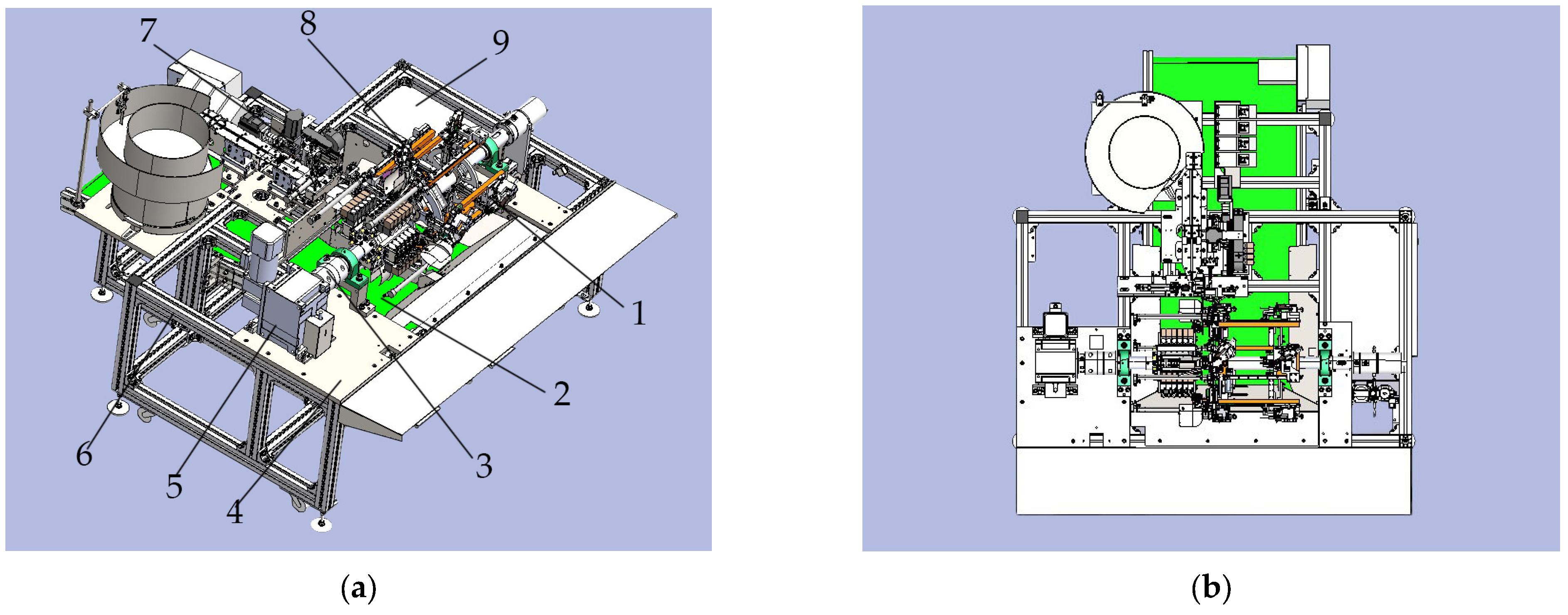
Figure 1. (a) Overall three-dimensional model design of the cucurbitaceous automated grafting apparatus: 1. Rootstock-Scion feeding station; 2. Rootstock-Scion discharging station; 3. Four-in-one rotating mechanism; 4. Worktable; 5. Drive motor; 6. Positioning frame; 7. Seedling binding station; 8. Rootstock-Scion cutting station; 9. Distribution box. (b) Top view of the three-dimensional model of the cucurbitaceous automated grafting apparatus.
Processes 13 03788 g001
Figure 2. Research process for automated grafting machines in cucurbit cultivation.
Processes 13 03788 g002
Figure 3. Automated grafting machine grafting process.
Processes 13 03788 g003
Figure 4. Analysis diagram of rootstock cutting operations: 1. Retain the cotyledons; 2. Seedling pressing trajectory; 3. Growing point; 4. Removal of cotyledons; 5. Resected portion; 6. Cutting path.
Processes 13 03788 g004
Figure 5. Analysis diagram of grafting cutting angles: (a) Analysis of the cutting angle of the scion. (b) Analysis of rootstock cutting angles.
Processes 13 03788 g005
Figure 6. Schematic diagram of synchronous cutting mechanism: 1. Rootstock separation plate; 2. Tool holder; 3. Indexing pin; 4. Knife box; 5. Knife handle; 6. Fixed knife holder; 7. Blade; 8. Knife slot.
Processes 13 03788 g006
Figure 7. (a) Before cutting the rootstock and scion. (b) After cutting the rootstock and scion.
Processes 13 03788 g007
Figure 8. Blade mounting structure.
Processes 13 03788 g008
Figure 9. Layout of cotyledon separation positions on rootstocks: 1. Rootstock; 2. Positioning block; 3. Cutting path; 4. Rootstock separation board.
Processes 13 03788 g009
Figure 10. (a) Schematic drawing of the rootstock and scion clamping mechanism: 1. Rootstock tool positioning block; 2. Rootstock separation plate; 3. Rootstock positioning block; 4. Rootstock clamping jaw; 5. Rootstock seedling; 6. Rootstock finger cylinder; 7. Rootstock knife groove; 8. Scion positioning block; 9. Scion clamping jaw; 10. Scion tool positioning block; 11. Scion finger cylinder; 12. Scion knife groove; 13. Scion telescopic cylinder; 14. Scion seedling; 15. Scion slide block. (b) Schematic diagram of cleft grafting for grafting seedlings.
Processes 13 03788 g010
Figure 11. Common grafting clamps for the whip grafting method. 1. Polyethylene butterfly clip; 2. Sleeve grafting clamp; 3. Handmade grafting clamp (red); 4. Handmade rafting clamp (green); 5. Domestic-Specific grafting clamp.
Processes 13 03788 g011
Figure 12. 3D model for grafting clamps.
Processes 13 03788 g012
Figure 13. Geometric parameters of grafting clamp: 1. Clamp body tail section; 2. Grafting clamp opening; 3. Grafting connection point; 4. Spring steel ring.
Processes 13 03788 g013
Figure 14. Force analysis diagram of grafting clamp.
Processes 13 03788 g014
Figure 15. (a) Compression process of the grafting clamp body tail section: 1. Presser head; 2. Support; 3. Initial state grafting clamp; 4. Ultimate state grafting clamp. (b) Compression load versus displacement relationship curve.
Processes 13 03788 g015
Figure 16. (a) Three-dimensional model of the clamping device for the grafting machine: 1. Guide rod; 2. Vibrating feeder; 3. Primary linear clamp feeding mechanism; 4. Photoelectric distance sensor; 5. Clamp receiving box; 6. Single-rod clamp supply cylinder; 7. Clamp slot; 8. Secondary linear clamp feeding mechanism; 9. Vibrating feeder; 10. Mounting base; 11. Switch controller; 12. Positioning frame; (b) Schematic diagram of linear vibratory feeder; (c) Schematic diagram of grafting clip separation mechanism.
Processes 13 03788 g016
Figure 17. (a) Schematic diagram of the upper clamping mechanism: 1. Wire straightener 2. Lifting stepper motor 3. Advancing stepper motor 4. Pusher rail 5. Lifting stepper motor 6. Grafting clamp fingers 7. Fixed stop plate 8. Grafting clamping cylinder 9. Grafting clamp fingers; (b) The process of pinching and wrapping seedlings.
Processes 13 03788 g017
Figure 18. (a) Grafting stock. (b) Grafting test apparatus.
Processes 13 03788 g018
Figure 19. (a) Grafting onto rootstock. (b) Grafting onto the rootstock. (c) Cutting the growth point of rootstock. (d) Cutting of scion stems.
Processes 13 03788 g019aProcesses 13 03788 g019b
Figure 20. Operational process of the grafting device for melons: (a) Seedlings on rootstock. (b) Seedlings on the scion. (c) Simultaneous cutting of rootstock and scion. (d) Grafting onto rootstock seedlings. (e) Vibratory feeder sorting. (f) Direct-vibration mechanism chuck feed. (g) Upper clamp device release mechanism. (h) Bandaging completed. (i) Recovery of finished seedlings.
Processes 13 03788 g020
Figure 21. Single-plant seedling grafting image: (a) rootstock seedlings; (b) scion seedlings; (c) grafted seedlings.
Processes 13 03788 g021
Table 1. Automatic cucurbit grafting machine vs. manual grafting: cost comparison.
Comparison ItemsAutomated Cucurbitaceae Grafting MachineManual Grafting
Grafting efficiency (plants/hour)1200–1500200
Operating cost (RMB/hour)15–2050 (per person)
Cost per plant (RMB/plant)0.2–0.30.5–0.6
Main cost componentsEquipment depreciation, energy consumptionLabor wages
Table 2. Matching degree of rootstock and scion length and cutting angle.
Cutting Angle
α (°)
Rootstock: Yongzhen No. 2Scion: Yongtian No. 5
Average Value
D (mm)
Bevel Length
L2 (mm)
Mean Stem Diameter
d (mm)
Bevel Length
L1 (mm)
203.17 ± 0.129.27 ± 0.122.66 ± 0.157.78 ± 0.21
257.50 ± 0.166.29 ± 0.14
306.34 ± 0.185.32 ± 0.20
355.53 ± 0.194.63 ± 0.17
404.93 ± 0.154.14 ± 0.15
454.48 ± 0.133.76 ± 0.13
Table 3. Comparison of clamp specifications and parameters.
Clamp TypesFigure
Number
Internal
Diameter
(mm)
MaterialsSuitable CropsCharacteristics
Polyethylene butterfly clip12.0~2.5PolyethyleneSolanaceaeModerately resilient, suitable for seedlings with slender stems of uniform diameter
Sleeve grafting clamp22.5~3.5Transparent elastic plasticSolanaceaeNo dismantling required; adapts to different stem thicknesses of Solanaceae seedlings.
Handmade
grafting clamp(red)
31.2~2.5Rigid plasticSolanaceaeThe stems possess moderate rigidity, with some featuring support holes to aid in securing them.
Handmade
grafting clamp(green)
41.5~3Flexible plastic and metal springSolanaceaeThe stems possess high rigidity, and the spring exhibits substantial compressive force.
Domestic-Specific grafting clamp53~15Polyethylene and metal springCucurbitaceaeCapable of securing sturdy rootstocks, providing sufficient clamping force.
Table 4. Grafting clamp specifications.
Clamp Body MaterialClamp WidthExternal Fix Action Point DistanceClamp Tail Distance Spring
Steel Ring Diameter
Wire Diameter Quality of Grafting Clamps
L (mm)B (mm)E (mm)D (mm)d (mm)m (g)
pe polyethylene9.51.52017101
Table 5. Safety Verification Results for Grafting Clamps.
Test SubjectStem Diameter
(mm)
Elasticity Limit of Seedlings (N)Jaw Opening
(mm)
Clamp Tail Compression (mm)Average Clamping Force (N)Maximum Clamping Force (N)
Sheng Zhen No. 14.22 ± 0.426.294.92 ± 0.228.21 ± 0.290.850.80
Guazhen No. 154.14 ± 0.396.974.69 ± 0.258.01 ± 0.340.790.76
Yongzhen No. 23.66 ± 0.306.834.18 ± 0.277.69 ± 0.420.750.71
Xi Yu No. 12.76 ± 0.445.743.36 ± 0.226.87 ± 0.370.640.61
Yao Long 252.73 ± 0.465.353.28 ± 0.306.69 ± 0.400.620.58
Yongtian No. 52.69 ± 0.325.173.16 ± 0.236.58 ± 0.250.590.54
Table 6. Cutting verification test results.
Test NumberRootstock: Yongzhen No. 2Scion: Yongtian No. 5Bevel Fit Rate
(%)
Sample Size
(plants)
D Value
(mm)
Bevel Length
(mm)
Sample Size
(plants)
Shaft Length
(mm)
Bevel Length
(mm)
1503.176.34502.646.2498.4
2503.126.24502.676.3198.9
3503.216.42502.626.1996.4
4503.066.12502.576.0899.3
5503.236.46502.726.4399.5
Average503.176.32502.646.2498.7
Table 7. Performance testing of the butt grafting: Scion: S, Rootstock: R.
Test NumberSample SizeSeedling Loading Rate
(%)
Cutting Success Rate
(%)
Upper Clamp Success Rate
(%)
Grafting Success Rate
(%)
Grafting Productivity
(plants/h)
SRSR
1100989997989891.301432
21001009898979992.221456
3100999898969990.361475
410097100959910091.221463
5100989998989893.191472
Average10098.4098.897.2097.698.891.671460
Disclaimer/Publisher’s Note: The statements, opinions and data contained in all publications are solely those of the individual author(s) and contributor(s) and not of MDPI and/or the editor(s). MDPI and/or the editor(s) disclaim responsibility for any injury to people or property resulting from any ideas, methods, instructions or products referred to in the content.