1. Introduction
A new round of scientific and technological revolutions and industrial transformations is accelerating. In order to promote the deep integration of intelligent technology and traditional manufacturing industry, the world’s manufacturing powers are seeking new innovative breakthroughs to seize the development opportunities brought by the new round of industrial revolution [
1]. As an important part of China’s traditional industry, products from the forging industry are used throughout the automotive industry, aerospace and other important fields, with internal tightness, uniform and reliable, large-scale production, and comprehensive good characteristics. With the continuous advancement of the dual-carbon strategy globally, green manufacturing has become a core direction of the automobile and forging industries, as it emphasizes energy conservation, material efficiency, and life-cycle environmental performance [
2]. Forging presses are energy-intensive equipment, and their structural optimization (e.g., lightweight design while improving stiffness) is a key link to achieve green manufacturing, which can reduce energy consumption during operation and material waste in production [
3].
Forging presses are the core equipment of intelligent forging production lines. The final results of the machine tool structure design must not only meet basic requirements, such as functional requirements, quality stability and processability, but also further enhance the load capacity of key components, improve strength and rigidity, increase operational precision and extend service life. This is a strong guarantee for ensuring product quality, improving reliability and reducing production costs. Forging presses are large in volume, structurally complex and tend to be integrated, making them relatively bulky with high inspection costs [
4]. In addition, the literature has also reported that the propagation of stress waves (generated by dynamic impact loads on machine tools) inside the machine tools can produce a stress amplification effect [
5] and make structural damage more likely [
6]. The precision of the press directly affects the cycle life of dies [
7], the processing accuracy of products and the product qualification rate [
8]. Therefore, the precision of forging and pressing equipment is a hotspot in the industry at current stage.
The development of high-precision presses is a systematic project in which the rigidity of the machine tool structure itself plays a fundamental role in the precision of the press [
9]. Presses with greater rigidity experience less deformation under load during production line operation, resulting in higher machine accuracy, which can improve production efficiency and quality, and improve the stability and accuracy of data feedback in intelligent forging production lines [
10]. Modern structural design methods use physical equations to describe the mechanics of structures, and comprehensively use finite element technology, numerical calculation methods and other means for structural optimization. The design method includes three levels: structural topology, size optimization and shape optimization. Topology optimization refers to the process of optimizing the arrangement of materials and structures within a given design space according to a set of defined rules, which can be traced back to Michell’s [
11] truss design theory. Size optimization, proposed by Schmit [
12], is a kind of parametric optimization technique that can optimize various parameters of a structure. Shape optimization is a structural optimization design method, first proposed by Zienkiewicz [
13] in the design of box structures, and is a technique for optimizing the boundaries or shapes of structures. Topology optimization is a revolutionary optimization technique that realizes performance-driven forward design patterns and is widely used in structural optimization. It is the most creative and practically valuable optimization design method. Eilam Amir [
14] proposed a layered construction method that embeds overhang restrictions and support structure requirements in topology optimization, suitable for high-resolution topology optimization. Zhao [
15] used the variable density method and SIMP interpolation method to perform topology optimization on the transport bracket of the rod delivery mechanism, resulting in a lighter and stiffer structure. Tiago [
16] studied the part design problem of non-penalty smooth edge material distribution topology optimization algorithms under nonlinear limit states. Chen [
17] used the topology optimization method to design a new joint that is manufactured using selective laser melting with high design flexibility. Topology optimization (TO) excels in exploring innovative material distribution for press frames, as it can identify optimal force-transmission paths in complex load scenarios and avoid redundant material [
18,
19]. However, its drawbacks include high post-processing complexity—optimized topological configurations often require regularization (e.g., adding reinforcement ribs) to meet manufacturing requirements. Size optimization is more applicable for parameterized adjustment of press frame components (e.g., thickness of side walls, width of reinforcement ribs), with low computational cost and easy integration with manufacturing [
20]. Yet, it relies on initial structural topology, making it difficult to improve inherent stiffness defects of traditional frames. Shape optimization focuses on boundary refinement (e.g., filet radius of crankshaft holes, contour of upper crossbeams), which can reduce stress concentration in local areas of press frames [
21]. However, it has limited effect on overall stiffness improvement, as it does not change material distribution in the design domain.
The effect of dynamic loads on structural design has always been an important issue in press design. The typical load of forging and stamping machines is a continuously cycling impact load that depends on the process of the part, and the load frequency is much lower than the natural frequency of the structure, but generally higher than the dynamic energy dissipation frequency of the structure. However, standard press machine design theories and methods rarely consider the comprehensive effect of complex working conditions on the structural design, often focusing only on static stiffness for numerical analysis and design of the structure [
22,
23]. This comprehensive design process directly leads to design schemes that may be insufficient in stiffness or wasteful in terms of materials in practical use. As early as the 1990s, many scholars identified this phenomenon and conducted related research. For example, Nagamatsu [
24] established a discrete model of 32 components for an open C-type press and used dynamic simulation analysis to optimize the design of the configuration. In the further development of press topology optimization, Son [
25] proposed a structural design for hot forging presses based on impact control methods. Yan [
26] proposed a buffer structure design for stamping presses to reduce the impact of impact loads on machine dynamics and noise. Inspired by the functional adaptation process of bones, Tovar [
27,
28] proposed the hybrid cellular automata (HCA) method. Its core idea is to combine the local evolution rules of cellular automata with the structural analysis capability of Finite Element Analysis (FEA) and iteratively adjust the material distribution through distributed control cycles to achieve the optimal configuration of the structure. This method has been demonstrated to be an effective approach for transient dynamic stiffness optimization of structures. In recent years, this approach has been successfully applied to the transient dynamic impact stiffness single-objective optimization design of automotive whole vehicles [
29,
30]. The HCA method has been successfully applied to the transient dynamic impact stiffness single-objective optimization design of vehicles, local parts, and other structures [
31]. It can be anticipated that by introducing the HCA method and integrating advanced structural topology optimization design techniques with advanced manufacturing technologies for high-precision hot forging presses, the development of structure optimization theories and design methods aimed at high-precision machine tools will aid in understanding the transient dynamic response characteristics of hot forging presses and achieve transient dynamic stiffness optimization design for these presses.
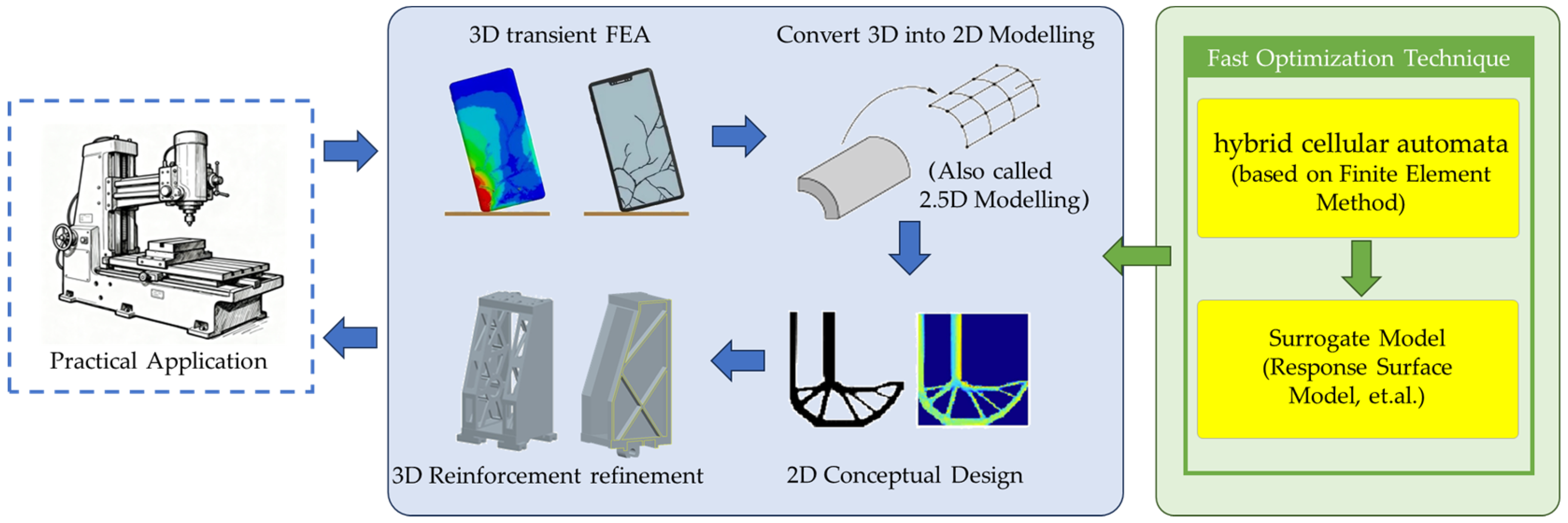
Scholars have conducted extensive research on the structural optimization design of various mechanical equipment, continuously advancing machinery towards integration, lightweighting, and structural stability. However, there is relatively little work on the dynamic stiffness optimization design of press support structures considering long-term transient impacts. This paper addresses the material distribution problem of the press machine frame support structure, utilizing variable density topology optimization design combined with response surface and particle swarm optimization. The objective of this study is to employ swarm optimization for robust design methods to perform dynamic and static structural optimization on the frame support structure. To this end, the JH31-250 forging press has been selected as the research object. The aim is to analyze and study methods and ideas to improve the stiffness of the press machine frame structure and the precision under working conditions. The workflow includes 3D modeling, transient FEA, 2D HCA optimization, and size refinement using response surface and PSO methods, as shown in
Figure 1. Furthermore, the study will explore optimization design methods for the machine frame structure under long-term transient impact conditions.
In summary, the main contributions of this work are threefold:
While the 3D model of the press has been utilized in prior static optimization studies [
19], this paper presents a transient stiffness-driven design for the same structure. We shift the focus from static performance to the dynamic structural response under realistic forging impact loads, which is a critical yet less explored aspect in press frame design.
We propose a simplified yet effective 2D HCA-based workflow to address the computational challenges associated with transient topology optimization of large, complex 3D structures. This approach bridges the gap between high-fidelity simulation and practical engineering design cycles.
The HCA method serves as a conceptual design guide to identify critical load paths and material distribution under dynamic conditions. The subsequent size optimization refines this conceptual layout. This hybrid strategy (Topology -> Size) is more efficient and provides deeper insight than applying size optimization alone to an initial guess structure.
2. Problem Description
The model design of the JH31-250 press is carried out based on the textbook
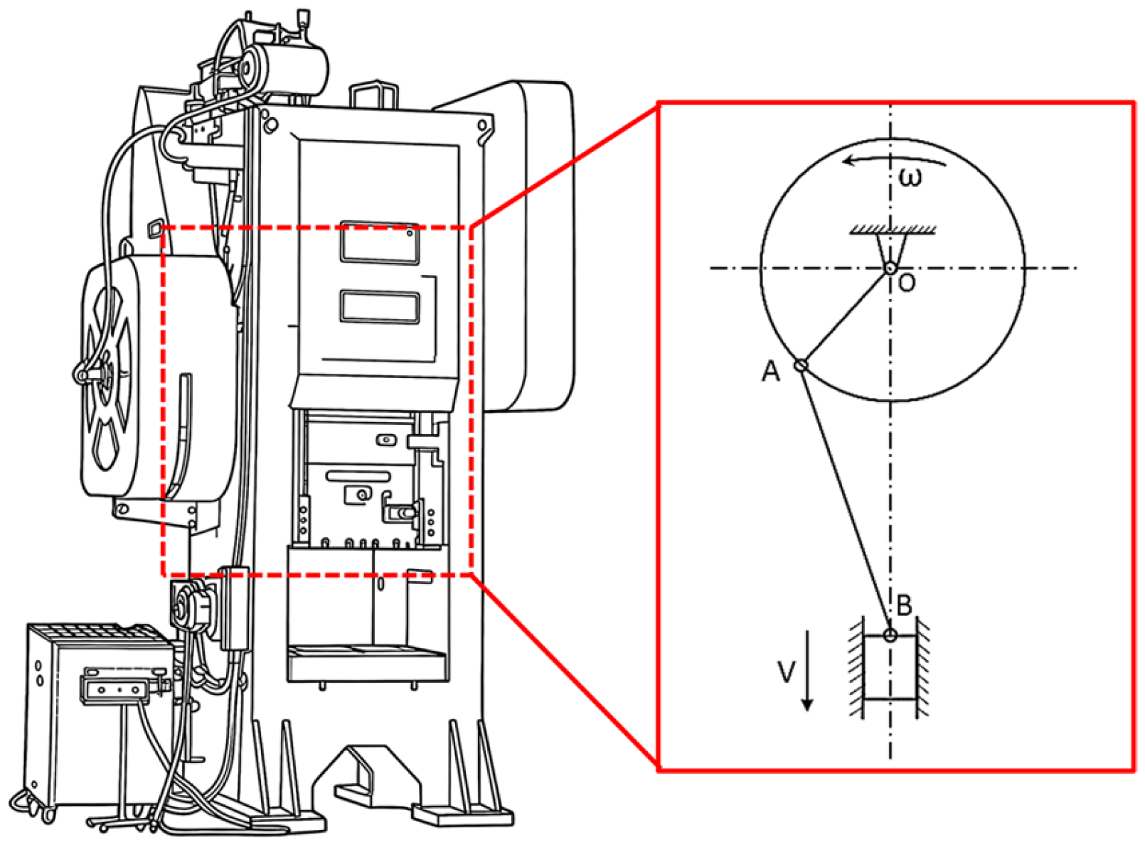
Crank Press (published in 1995) by Professor He Deyu from Tsinghua University. This machine tool is easy to assemble, has good vibration damping performance, is more suitable for large-scale production, and serves as the core equipment in forging production lines. The JH31-250 press comprises a number of key components, including the frame, worktable, transmission structure, clutch, and brake. The press’s operational principle hinges on the conversion of the crankshaft’s circular rotation into the reciprocating linear motion of the slide block, facilitated by a crank–slider mechanism. This is illustrated in the accompanying simplified diagram.
Figure 2 illustrates the motion of the slide block from JH31-250. The upper die is fixed to the slide block, while the lower die is fixed to the worktable. By utilizing the linear motion of the slide block, the dies are closed, and the workpiece is subjected to strong compression, resulting in plastic deformation or fracture of the metal material. This enables the processing and production of parts. During the forging process, the load on the press is a short-term impact load. When the press is in the return stroke, the motor drives the flywheel to accelerate and store energy. When in use, the flywheel decelerates and releases energy, forming the instantaneous impact load required for forging.
In this context, Point O represents the center of rotation of the crankshaft, Point A represents the connection point between the crankshaft and the connecting rod, Point B represents the connection point between the connecting rod and the slide block, OA is the crankshaft radius, and AB is the length of the connecting rod. When OA rotates at an angular velocity of ω, the slide block performs reciprocating linear motion up and down at a velocity of v.
The frame serves as the principal load-bearing component of the forging press and is also the largest component, accounting for over 60% of the total machine weight. It is essential that the frame withstand the deformation forces generated by the press during operation while ensuring the precision of the slide block. This is of particular importance with regard to the performance characteristics of the entire machine. The objective is to distribute the mass and structure of the press frame in a reasonable manner, thereby enhancing its rigidity and working precision, reducing deformation displacement and increasing the service life of the press. These factors have become key to the structural optimization design of the press.
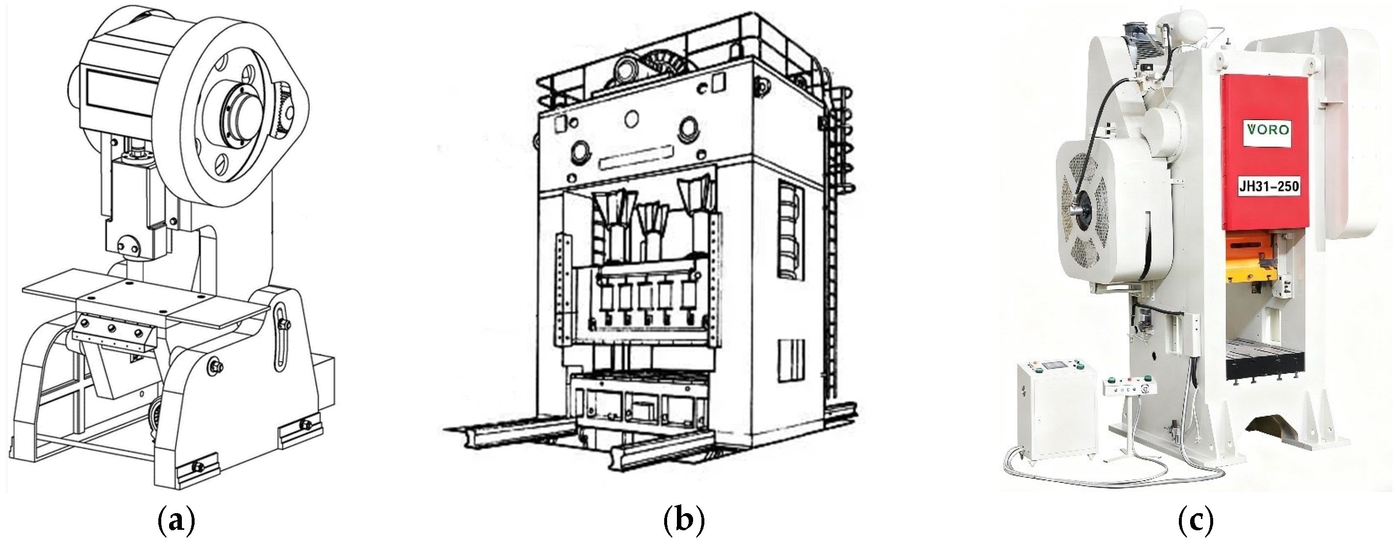
Presses can be classified into two main categories: open-back and closed-back. This classification is based on the frame structure, as illustrated in
Figure 3a,b. Open-back presses typically feature a C-type frame, which is susceptible to corner deformation and exhibits relatively poor rigidity. However, they are advantageous in terms of operational convenience and equipment maintenance. Closed-back presses employ a rigid frame structure to reduce deformation during operation, thereby enhancing processing precision, which However, comes at the expense of operational and maintenance convenience. The main research object of this paper is the JH31-250 press, as shown in
Figure 3c. This model of press has a closed integral frame structure, which is convenient for assembly, has good vibration absorption, and is more suitable for mass production. The frame is mainly composed of four major structures: two distinct walls that support structures, the upper crossbeam, the lower base, and the worktable.
The JH31-250 model press is a closed single-point press. In analyzing the stress and deformation of the frame, a nominal force of 2500 kN is used as the external load on the frame. From the main technical parameters of the JH31-250 press, it can be seen that the nominal force of the press is 2500 kN, which means that the maximum pressure exerted by the slide block on the worktable is capable of withstanding a load of 2500 kN. Additionally, the dimensions of the crankshaft height, worktable, slide block, and other relevant specifications have been provided. During operation, the frame primarily experiences two distinct loads. One is a point load acting vertically upward on the crankshaft support hole, while the other is a uniformly distributed load acting downward on the worktable.
The primary load-bearing components of the press machine are the frame and the worktable. The selection of material parameters for these components is of great consequence, as it directly impacts the structural analysis outcomes. The frame is welded and constructed using Q235 steel plate [
32], while the worktable is made from QT500-7 [
33]. For detailed parameters, please refer to
Table 1.
The pressure applied to the surface area of the worktable is:
where
F represents the workload, and
A represents the area of the worktable subjected to the force. load on the crankshaft support hole is relatively complex. When the crankshaft and the support hole are in a clearance fit, the contact pressure distribution is a cosine function [
34]:
In this equation, Fmax refers to the maximum load on the support hole of the crankshaft, and α is the circumferential position coordinate of the shaft hole, and it is zero at the symmetric center of the contact surface between the crankshaft and the hole.
The ongoing automation and intelligentization of forging production lines has led to an increased demand for precision in the processing of core equipment, such as presses. The slide experiences severe impact as it approaches the lower dead point, and the repeated cyclic application of loads subjects the worktable to continuous impact dynamics, causing the frame to undergo time-varying dynamic deformation. The dynamic performance and vibration analysis of such equipment are becoming increasingly important.
The JH31-250 press represents a typical closed-frame design with high productivity demands. However, its existing structure exhibits significant deformation under transient loads, affecting machining accuracy and necessitating optimization. The optimized formulation of structural dynamic problems varies with different dynamic response objectives, and the optimized structures also differ accordingly [
35]. Here, we ignore the deformation of the crankshaft, and only the deformation of the press side plates is considered. In this case, the accuracy error of the worktable is equal to the relative displacement between the upper connection (of the press side plates) with the crankshaft and the lower connection (of the press side plates) to the worktable.
3. Transient Finite Element Analysis
3.1. Finite Element Modeling of JH31-250 Press
The JH31-250 press’s principal parameters are used as the basis for creating a 3D solid model of the press frame in SolidWorks 2018. This model is then imported into finite element software to complete the creation of the finite element model. Subsequent to this, structural characteristic analyses are conducted, including assessments of strength, stiffness, and natural frequency. These analyses provide a foundation for the optimization design of the press frame structure.
The gusset plate structure of the press frame is predominantly connected through welding or bolting, and its structural shape is relatively complex. The geometric structure of the frame has been simplified and regularized, with the exclusion of minor features such as round holes, filets, and chamfers that have been deemed to have minimal impact on the structural performance. Additionally, unnecessary protrusions, including welds and small edge parts, have been removed. Threads for assembly, rivet holes, and oil holes have also been deleted. The contact surfaces between bolted connectors were simplified using bonded constraints, and all welded positions were connected by means of geometric common nodes. The crankshaft is modeled as a rigid body, and the simplified 3D solid model and the finite element model of the press frame are presented in
Figure 4 for reference. The finite element model established in this paper exhibits no material nonlinearity, contact nonlinearity, or geometric nonlinearity. The current simplified scheme is developed based on the operating characteristics of frame-type crank presses. However, the method proposed in this paper is capable of handling nonlinear scenarios. If readers need to analyze issues caused by nonlinearity (such as local connections or problems arising when using feedback control systems like servo motors), they can also apply the methodological framework of this paper.
In order to ensure good field contour, the JH31-250 press has been meshed with ten-node bilinear tetrahedral elements, with a size of 50 mm. In the process of mesh division, it is essential to adhere to the following principles [
36]: (1) For smaller structures, such as filets, chamfers, and threaded holes, distorted meshes are likely to occur and should be eliminated as much as possible. (2) If the removed structural parts are located in areas of stress concentration, they cannot be simply disregarded and require further mesh division to ensure a more gradual transition with the surrounding meshes. The outcome of the frame meshing is illustrated in
Figure 4b, resulting in a total of 90,633 elements and 169,521 nodes.
The press frame is affixed to the ground. In this study, the boundary conditions are defined by fully constraining the displacement degrees of freedom of all nodes on the machine tool base. The coupling constraints in the finite element software are employed to couple the central spatial node RP1 of the crankshaft hole with the overall force surface of the crankshaft hole, and to couple the central spatial node RP3 of the worktable with the entire surface of the worktable. By applying corresponding loads at characteristic points, the loads on the crankshaft support hole and the uniformly distributed loads on the worktable are simulated.
3.2. Parameter Settings for Analysis
In this context, the contact surface of the crankshaft support hole is coupled with the spatial nodes, which allows for the simulation of the force exerted on the hole. In order to simulate the force exerted on the crankshaft hole, loads were applied to the spatial nodes. The maximum nominal pressure of 2.5 × 10⁶ N was taken as the load under the working condition of the frame, and the magnitude of the force was observed to undergo a periodic change within one impact cycle.
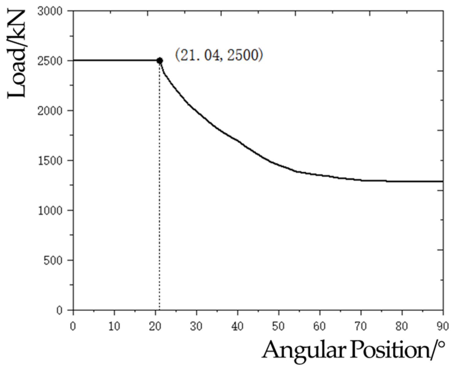
The nominal pressure of the press in question is 2500 kN, which occurs at a distance of 7 mm from the bottom dead point. The corresponding crank eccentric rotation angle is approximately 21.04°. As illustrated in
Figure 5, the pressure variation in the press under operational conditions is presented. Based on the pressure curve, the nominal pressure exerted on the worktable during the press’s working state can be approximated to be within the range of the crank eccentric rotation angle from 0° to 21.04°. The press operates at a frequency of approximately 0.53 Hz. The frequency of the load’s action is related to the production rhythm; if the entire ram running time is set to 1 s, then the nominal pressure acting time can be approximated to be approximately between 0 and 0.11 s. In finite element analysis we separate the 0–0.11 s into 20 frames and 0.11–1 s into 20 frames separately in order to capture the dynamic procedure.
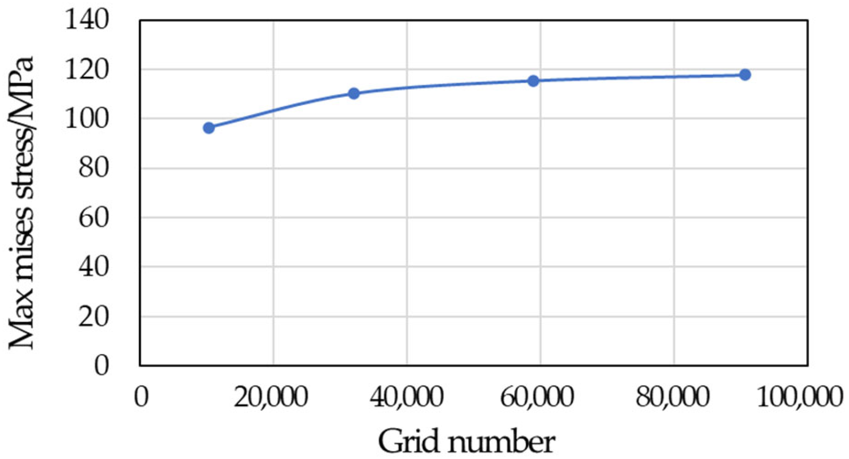
The dynamic performance of the machine tool under forging force impact analysis can be obtained from either time-domain or frequency-domain analysis methods. The numerical methods employed for time-domain transient dynamic analysis can be broadly classified into two categories: implicit algorithms and explicit algorithms. In comparison, implicit methods have stable errors but poor algorithmic convergence. Explicit dynamic analysis algorithms are relatively simple to implement and do not have significant convergence issues. They are therefore widely applicable to transient response analysis of structures, highly nonlinear quasi-static analysis, and other short-term dynamic problems such as blasting, collisions, and contacts. The utilization of explicit dynamic finite element methods for the simulation of the transient impact process of the machine tool allows for the specification of the corresponding working loads through the aforementioned pressure curve, thereby enabling the simulation of the internal force conditions of the press under real working conditions. In structural analysis, the significant mass of the machine frame necessitates the consideration of the effect of gravity, which must also be simulated in a gravitational environment. A mesh sensitivity analysis ensured convergence, with element sizes chosen to balance accuracy and computational cost, as shown in
Figure 6.
We input the analysis task (with 90,633 meshes) into commercial software (Abaqus 2021) using a personal computer with a hardware environment of an Intel i7 10,700 K and 32 GB RAM (without GPU acceleration), and the runtime cost was about 40 min.
Structural frequency-domain modal analysis, also referred to as steady-state dynamic analysis, is a linear analysis method designed to calculate the modal characteristics of product structures and mechanical components, including natural frequencies and mode shapes. Should the press be subjected to significant mechanical vibrations during operation, this can have a considerable impact on the service life of the press and dies, the precision of product processing, and may even resonate with other external excitation sources, causing significant damage to the overall structure of the press. The modal analysis requirements for the JH31-250 press can be broadly classified into two categories: (1) the low-order natural frequencies of the press frame should be such that they avoid the working frequency of the press; and (2) the low-order natural frequencies of the press frame should be such that they avoid the working frequency of the motor. This paper employs the Block Lanczos method for modal analysis of the press frame, which is a vector iteration method that offers high precision.
3.3. Discussion of the Transient and Dynamic Analysis Result
In transient dynamic analysis, the time step of 0.11 s is divided into 20 frames of equal duration, and contour maps of equivalent stress and deformation are plotted. As illustrated in
Figure 7 (during work, 3 frames are selected for illustration), the scale of the images is based on the maximum equivalent stress and deformation values experienced by the model under a load. From the contours, it can be observed that the stress distribution in the press machine’s frame is symmetrical on both sides under the transient forces. The stress in the frame is primarily concentrated around the crankshaft hole, the front end of the frame, and the front of the square hole, with fluctuations occurring in these areas. The maximum equivalent stress experienced by the frame during the variation process is 117.80 MPa. As a consequence of the load, the frame undergoes elastic deformation, with deformation displacement evident in the areas above the square hole. The upper end of the crankshaft hole exhibits a larger displacement, and the maximum overall displacement of the frame reaches 0.8845 mm, which has a considerable impact on the rigidity of the frame.
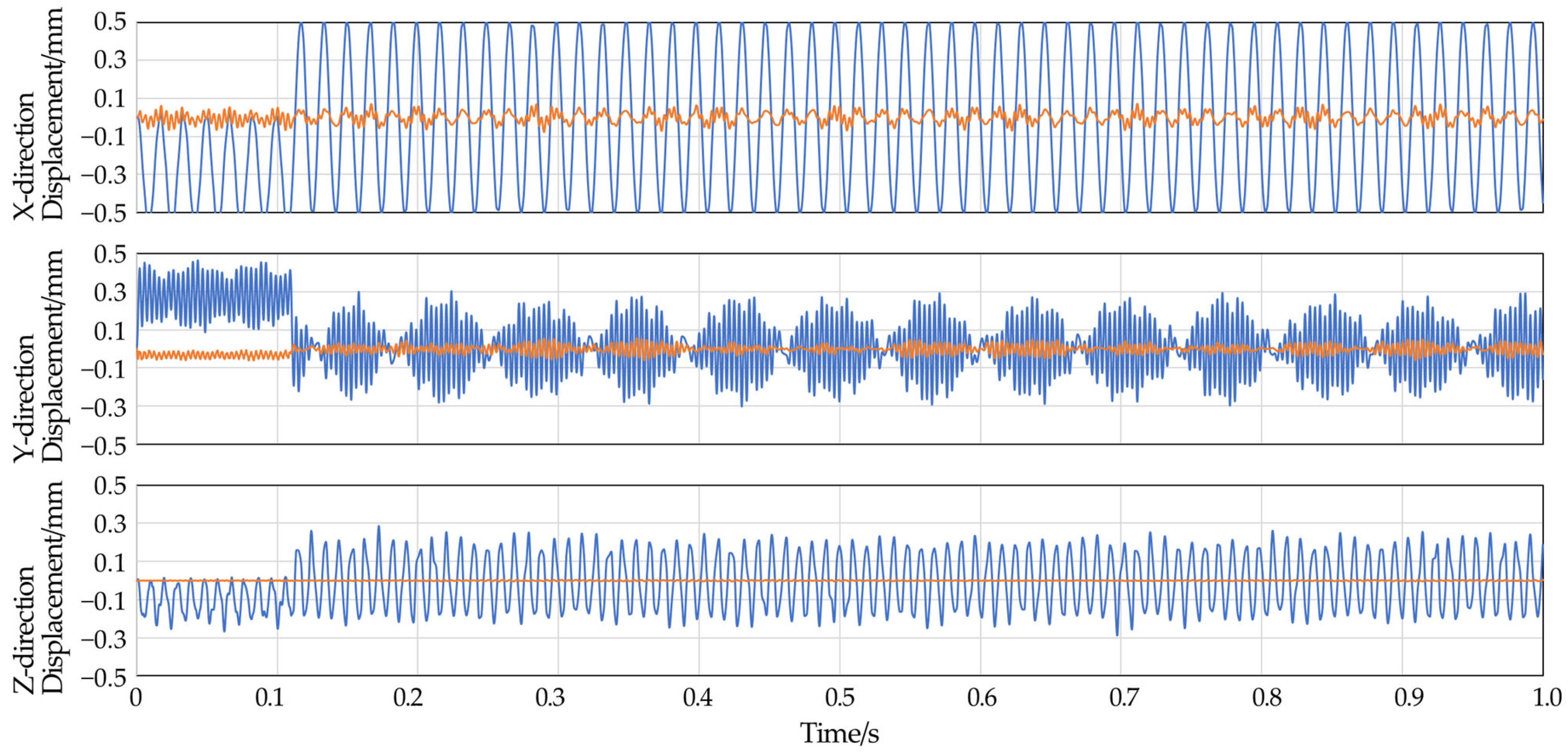
In the history output, the displacement values of nodes RP1 and RP3 in three directions over time are plotted as shown in
Figure 8.
The press machine generates forces that are largely borne by the frame, leading to certain deformations at work. The relative displacement between the crankshaft support hole of the frame and the worktable can cause damage to the dies and even affect product precision. Therefore, the relative deformation between these two locations is used as a criterion for judging the rigidity of the frame. It is also necessary to consider the effect of internal structural damping. From the displacement curve diagram, it can be observed that under the action of transient impact forces, the frame undergoes severe vibration. During the nominal pressure phase, the frame deforms due to the load, and the displacement fluctuates around this value. In other phases, the displacement fluctuates around zero. Considering that the load cycle is much longer than the natural vibration cycle of the structure, high-frequency oscillations can be observed superimposed on the low-frequency loading waveform. Due to the differing modal characteristics in various directions and the varying propagation speeds of stress waves, the overall waveform exhibits a Lissajous phenomenon over an extended period. A comparison of the relative displacement values of nodes RP1 and RP3 during the two phases reveals that the maximum displacement occurs during the nominal pressure load phase.
As we can see in
Figure 9, due to the action of non-periodic loads, the vibration and fluctuation laws inside the press structure are extremely complex after the load is released. To obtain a more accurate calculation result, it is necessary to increase the number of sampling points and to make the time-displacement curve smoother. This can be achieved by increasing the uniform time interval during the nominal pressure phase, which allows us to calculate a more precise maximum relative displacement of the frame. The maximum relative displacement between the selected node RP1, which corresponds to the crankshaft support hole, and the central node RP3 on the surface of the worktable, is taken as the criterion for judgment. The analysis results are presented in
Table 2.
From the data presented in the table, it can be observed that the deformation displacement around the crankshaft support hole is more pronounced in comparison to that of the worktable. This finding is consistent with the deformation contour plot of the frame, as shown in
Figure 10. When subjected to transient dynamic forces, the frame experiences intense vibration, resulting in a notable increase in the maximum relative displacement of the frame in comparison to that observed under static forces. This has a significant impact on the rigidity of the frame.
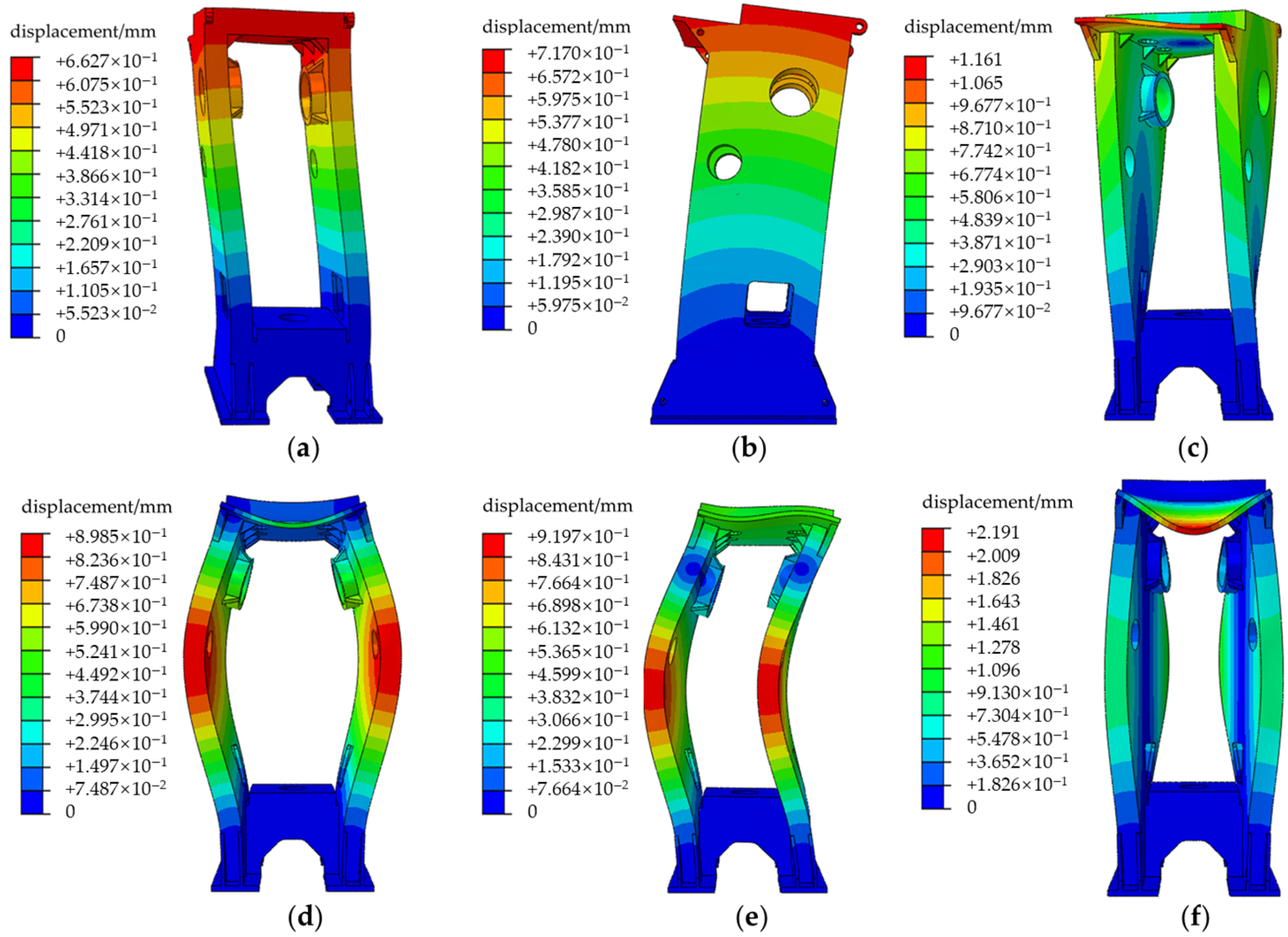
In the study of the steady-state dynamic performance of machine tools, the structural modes and mode shapes are observed. Given that potential dynamic damage to the frame is likely to be concentrated in the low-order modal resonance, the first six natural frequencies are extracted for analysis. The results can be found in
Table 3.
We conducted a frequency-domain analysis of the structure and obtained the corresponding natural frequencies and modal information. The vibration modes are presented in the form of displacement contour plots, where the displacement here is normalized displacement rather than actual displacement. Specifically, it refers to mass matrix normalization, which means each mode shape is scaled to satisfy the following equation:
In this equation, φᵢ is the shape vector of the i-th mode.
The press machine’s slide travels at a certain speed. This equates to 32 cycles per minute, which means that the actual working frequency of the press machine is 0.53 Hz. The first-order natural frequency of the press machine frame is approximately 22.21 Hz, which means that the low-order natural frequencies of the frame are significantly higher than the frequency of the external excitation sources. This prevents resonance from occurring. The motor utilized in this press machine is a four-pole three-phase asynchronous motor with a rated speed of 1000 revolutions per minute, which indicates that the working frequency of the motor is less than 16.67 Hz. In addition, this motor would be expected to have excitations at 16 Hz, 32 Hz, 48 Hz, and 64 Hz (higher-order harmonics of the electrical machine). However, the severity of resonance depends not only on frequency matching but also, more importantly, on the amplitude of the excitation source.
It is generally known that low-frequency components are often more abundant and possess higher energy in common excitation sources (such as ground vibration, wind, and machine operation). Additionally, from the perspective of structural dynamics, low-order vibration modes are usually easier to excite. This is due to the fact that the stiffness corresponding to low-order vibration modes is lower, while higher-order vibration modes require more energy to be excited. Therefore, this statement is common in engineering practice. However, it should be noted that this does not mean high-order resonance will not occur. Under specific excitation conditions—for instance, when the excitation frequency is close to the high-order natural frequency of the structure—high-order resonance can also take place. For the calculation example in this paper, it can be observed from
Figure 9 that the working load is more likely to excite vibrations around 60 Hz/104 Hz/170 Hz/275 Hz. Meanwhile, the high-order resonance frequency corresponding to the motor’s own operating frequency is also around 60 Hz. Consequently, for the JH31-250 studied in this paper, it is more prone to inducing resonance at the 2nd or 3rd order frequency. Nevertheless, no obvious resonance phenomenon has been observed in actual production, which indicates that the excitation energy is insufficient. In subsequent work, we will conduct a more in-depth study on this issue.
4. Algorithm and Methods of Transient Structural Optimization
The aforementioned simulation process demonstrates that existing finite element software is capable of performing dynamic performance analysis of structures.
Research indicates that the majority of commercially available software already incorporates algorithms for static and steady-state dynamic optimization. However, due to the intricate nature of dynamic deformation in the frame structure, static topology optimization is unable to fulfill the necessary design requirements and it is not feasible to achieve the optimal dynamic stiffness performance required for the frame structure. The column formulas for transient topology optimization are as follows [
37]:
The design variable of the above optimization formulation is the material distribution of the structure. Here, we introduce the concept of “elements” from the finite element method to describe such a discrete distribution of materials. Therefore, for n elements, the i-th element corresponds to a value of either “0” or “1” to indicate the presence or absence of material at that location, and this variable is defined as xi (pseudo-density). The objective of optimization, f(X), represents the stiffness or reference point displacement of the structure’s frame. The stiffness matrix (K), damping matrix (C) and mass matrix(M) are corresponding to those from transient finite element method. U is the vector of time-varying displacement. In addition, V is the volume of the optimized structure, and V* is the target volume of the structure to be optimized. The constraint condition is set as the volume fraction to ensure that the optimized model’s structural volume matches that of the model’s before optimization.
By solving the time-domain equations, the response history of a structure under impact loads can be calculated directly. This enables accurate capture of the maximum dynamic response of the structure when the impact occurs, which is exactly what the optimization objective of this paper (maximum relative displacement) focuses on. The primary challenge for transient dynamic optimization at present is computational efficiency [
38]. Consequently, it is essential to identify suitable optimization algorithms and undertake secondary development of finite element software. It is worth noting that in the case of linear elasticity, the governing equations of this optimization problem can be transformed into frequency-domain equations, thereby reducing the requirement for computational capacity. However, we choose time-domain method in this article in order to build a more general workflow, which can be extended to easily engineer nonlinearity.
4.1. Theory of Hybrid Cellular Automata for Structural Optimization
In light of the pivotal role played by transient dynamic stiffness performance in the structural design of presses and the current dearth of research on optimization methods for the transient dynamic impact stiffness of press frames, this section presents the theoretical basis of the hybrid cellular automata (HCA) algorithm, which combines the cellular automata (CA) with the finite element analysis. Cellular automata (CA) are mathematical models comprising a discrete spatial grid and a set of discrete state collections. The fundamental objective is to transform disordered, irregular, and unbalanced states into ordered, regular, and balanced states. CA can produce markedly disparate behaviors and outcomes under different rules and initial conditions, which have led to their extensive utilization in scientific research and computer simulations [
39]. The nonlinear transient finite element analysis is conducted using commercial finite element analysis software, while the relevant algorithms are implemented using self-written C++ code. This approach allows for the exploration of the topological optimization method of the frame structure under nonlinear impact load conditions, as illustrated in the research route depicted in
Figure 11.
The fundamental constituents of CA comprise five elements: cells, a set of states, cellular space, neighbors and evolution rules. It can be conceived as a system comprising a cellular space and a transformation function defined on that space. Cells represent the most elementary units of cellular automata, distributed at discrete positions in Euclidean space and exhibiting a discrete state. At any given moment, the cellular space is constituted by a set of grid points in Euclidean space, where cells are distributed. The most common type of cellular space is two-dimensional, as illustrated in
Figure 12. The state of the grid is described by the solid isotropic microstructures with penalization (SIMP). The evolution rules of a cellular automata are localized; the spatial domain searched when updating the state of a cell is defined as the neighborhood of that cell.
During the process of updating, the state of each central cell is influenced by its neighboring cells. In order to update the state of the central cell, it is necessary to compute information from all the cells within its neighborhood. For a discrete position,
i, and discrete time,
t, the state set of the cell can be represented as:
where
represents the state of the
i-th cell,
j presents the count of state variables.
In contrast to conventional dynamic models, cellular automata are not defined by a set of strict physical equations or functions; rather, they are composed of a set of rules that construct the model. All cells, including their neighbors, adhere to the same evolution rules, which are applied throughout the entire iterative process to achieve synchronized state updates of all cells. The mathematical expression for the evolution rules is:
where
(t) is the state of the
i-th cell,
is the state of the neighboring cells of the i-th cell.
N is the number of the neighboring cells,
is the local updating rules,
(
t + 1) is the state of the
i-th cell after iteration.
The fundamental tenet of the HCA optimization algorithm is that the total strain energy density within the optimization region can be quantified as the mechanical energy stored by deformation. It can be demonstrated that the greater the structural stiffness, the lower the strain energy density stored. During the iteration process, the cell density is updated in order to match the target strain energy density. Based on the impact load conditions that the machine frame experiences under working conditions, the average strain energy density is employed as the performance evaluation index of the frame structure. If the average strain energy density of all cell elements in the design domain is closer to the target average strain energy, the superior the performance of the machine frame structure. We set the penalized density from SIMP as the thickness of all elements within the design domain. By combining with the HCA algorithm, the cell element thickness evolves, and structural optimization design is carried out. The mathematical model for this optimization problem can be described as follows:
In the formula, the variable
ti represents the thickness of the
i-th element,
Si represents the area of the
i-th element.
V* is the target volume of the structure to be optimized. The average strain energy density target value in the design domain is defined as
U*, and the strain energy density values within
N cells are extracted as
Ui. Then, we can get the following equation:
The average strain energy density is calculated based on the values from all adjacent cells within the central cell’s domain, as shown in Equation (9)
where the variable
represents the number of neighbors of a cell,
represents the average strain energy density of the neighboring cells of the
i-th cell, and
Uij represents the strain energy density of the
j-th neighbor of the
i-th cell.
The difference between the average strain energy density and the local strain energy density of the
i-th cell is denoted as
ei. When
ei < 0, this indicates that the average strain energy density within the cell is relatively low, and the thickness of the cell should be reduced in order to decrease its stiffness. Conversely, when
ei > 0, the thickness of the cell should be increased in order to enhance its stiffness.
The evolution rule of a cell is localized, as is the state update rule. The former is defined as follows:
where
α is a linear parameter, Δ
ti(
k) is the thickness increment of the
i-th cell at the
k-th iteration.
In the process of structural static optimization, mathematical programming methods are frequently employed. Volume constraints can be directly transformed into a component of the objective function through the method of Lagrange multipliers. However, in dynamic optimization processes, due to the involvement of nonlinear dynamic responses and other optimization issues, obtaining the sensitivity of the optimization objective is a time-consuming process. Therefore, we adopt the optimality criterion method, using the achievement of volume constraints as the convergence criterion. By ensuring that the rate of change in the global strain energy is less than ε, we achieve global convergence.
where
V(
k) represents the total volume of the model’s material after the
k-th iteration step,
ΔV(
k) represents the total volume increment, and
ε represents the convergence precision.
4.2. Flow of Hybrid Cellular Automata for Structural Optimization
The HCA algorithm to optimize the structures of the press frame can be delineated into the following stages:
Model establishment. The initial stage of the process is the establishment of the model. The 3D frame model is converted into a 2D shell model, and a finite element model is established in finite element software. The next step is to determine the design domain, perform meshing, load constraints, and boundary condition settings on the shell model.
Discretization of the design domain. The design domain is then discretized, with each mesh element acting as a cell and having the same thickness. The number of neighboring cells within the cell domain is also determined; this paper uses eight adjacent cell model.
Program initialization. Various variable parameters are initialized, such as cell relative density, cell thickness, etc.
Model analysis. Finite element software is employed to perform a transient dynamic analysis on the shell frame model, with the objective of obtaining parameters such as stress and strain energy of the frame structure. A self-developed C++ program is then used to read the analysis result files, thereby achieving interaction with the software.
Cellular parameter updating. The thickness of the cellular elements should be updated using the HCA algorithm.
Convergence criteria. The convergence of the volume constraint should be determined based on the aforementioned criteria. If the convergence has not been reached, the process should be repeated from step 4. If the results have converged, the 2D frame topological conceptual configuration should be outputted.
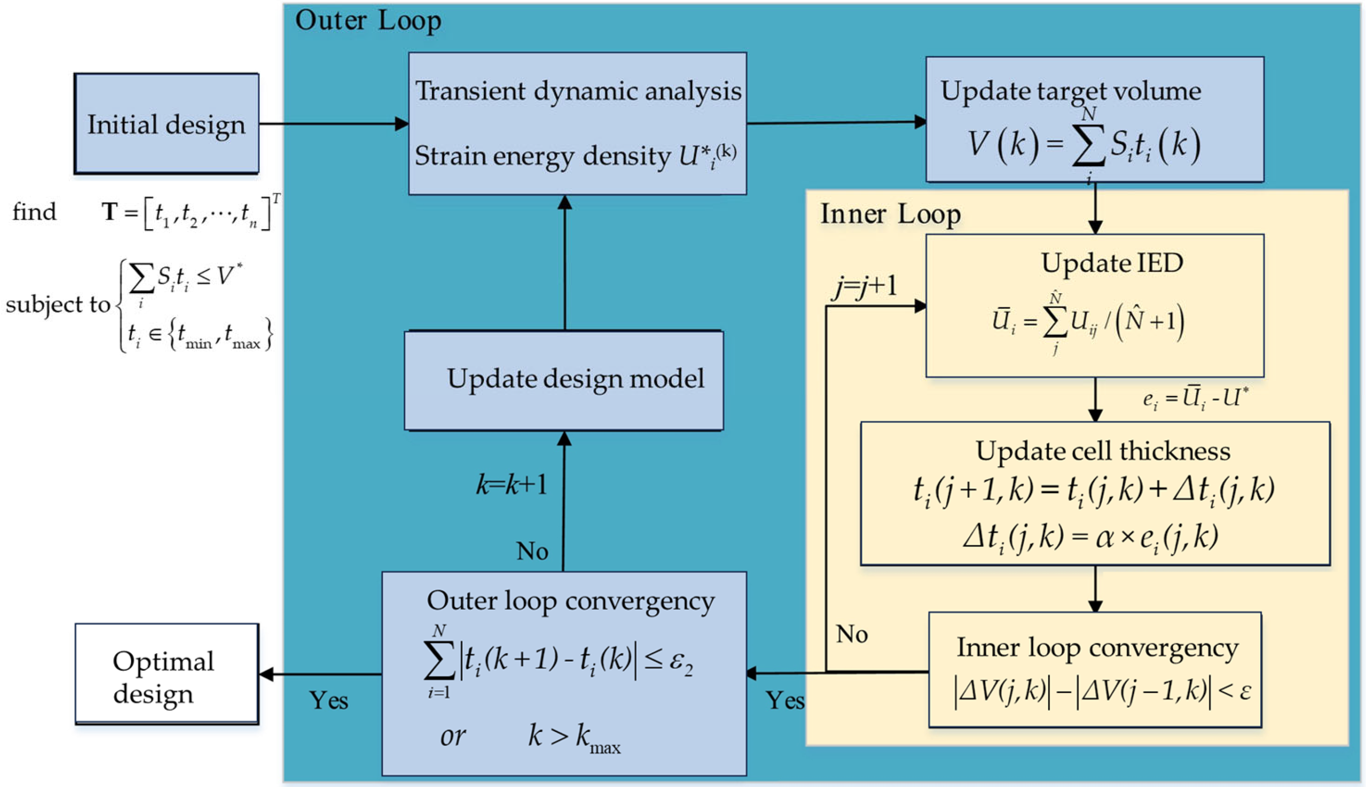
The numerical implementation process of the HCA algorithm can be divided into a two-layer loop structure, as shown in
Figure 13.
The structural dynamic optimization process described in this paper makes use of finite element software for implementation. Initially, the pre-processor of the software is employed to perform quadrilateral meshing, select element thickness, add material properties and set element node numbers for the press machine frame model to be optimized. This establishes a finite element model which is saved as an input file. Subsequently, the finite element main program is invoked through the command line to conduct a dynamic explicit analysis on the model, with the analysis results saved in a database file. Thereafter, a scripting language is utilized to write the HCA algorithm, which determines the iteration direction of cell thickness based on the current cell’s thickness and strain energy state. The strain energy data for each element in the database file is read by a script file to reduce the computational load of cell traversal. The adjacency information of cells is deduced and saved as a fixed array, comprising node adjacency relationships, which are then read directly from this array. Through repeated iteration of this process, the topological optimization of the model structure elements can be achieved.
The HCA algorithm operates by reducing the thickness of cells with larger local strain energy and increasing the thickness of cells with smaller local strain energy. This directional change in cell thickness results in convergence, thereby achieving the topological optimization of the structural design area within the model. The secondary development work of this commercial software has enhanced the flexibility and versatility of the HCA algorithm in nonlinear structural optimization problems.
After the HCA process is implemented, it is necessary to further convert the 2D model back to a 3D model. When reverting to the 3D solid model, the thickened regions of the wall derived from the 2D topology optimization are modeled as reinforcement ribs and plates of the frame structure, so as to reflect the characteristic of the press in manufacturing, where an integrated structure is formed by welding metal plates. This is consistent with the original modeling approach described in
Section 3.1.
5. Structural Transient Topology Optimization
5.1. Establishment of Topological Optimization Model
The material parameters selected for the machine frame shell model correspond to the actual materials, as detailed in
Table 1. As the shell model is derived from the 3D solid model, it is necessary to achieve variations in material thickness during the structural optimization phase. It is necessary to establish the initial thicknesses and material properties for the various regions of the shell model in accordance with those of the solid model. For instance, the side shell elements are composed of Q235-B material with a shell thickness of 195 mm.
Press machines have large volumes and the 3D simulation calculation is time-consuming. Furthermore, the traditional HCA algorithm is more challenging to calculate and solve complex three-dimensional solid mesh models and to handle nonlinear problems. Consequently, in the process of structural optimization of the press machine frame based on the principles of HCA impact dynamics, the complex 3D structure is transformed into a 2D mechanical model, specifically a shell element model. This facilitates the rapid conceptualization of the model using the HCA algorithm. Subsequently, the 3D structure is reverted to during the dimensional optimization process.
In the HCA algorithm, the 2D cellular automata with an 8-neighbor model is selected. The 3D solid press machine frame model must be transformed into a 2D shell model, after which a transient dynamic analysis can be performed on the shell model elements. The transformed press machine frame shell model and finite element model are shown in
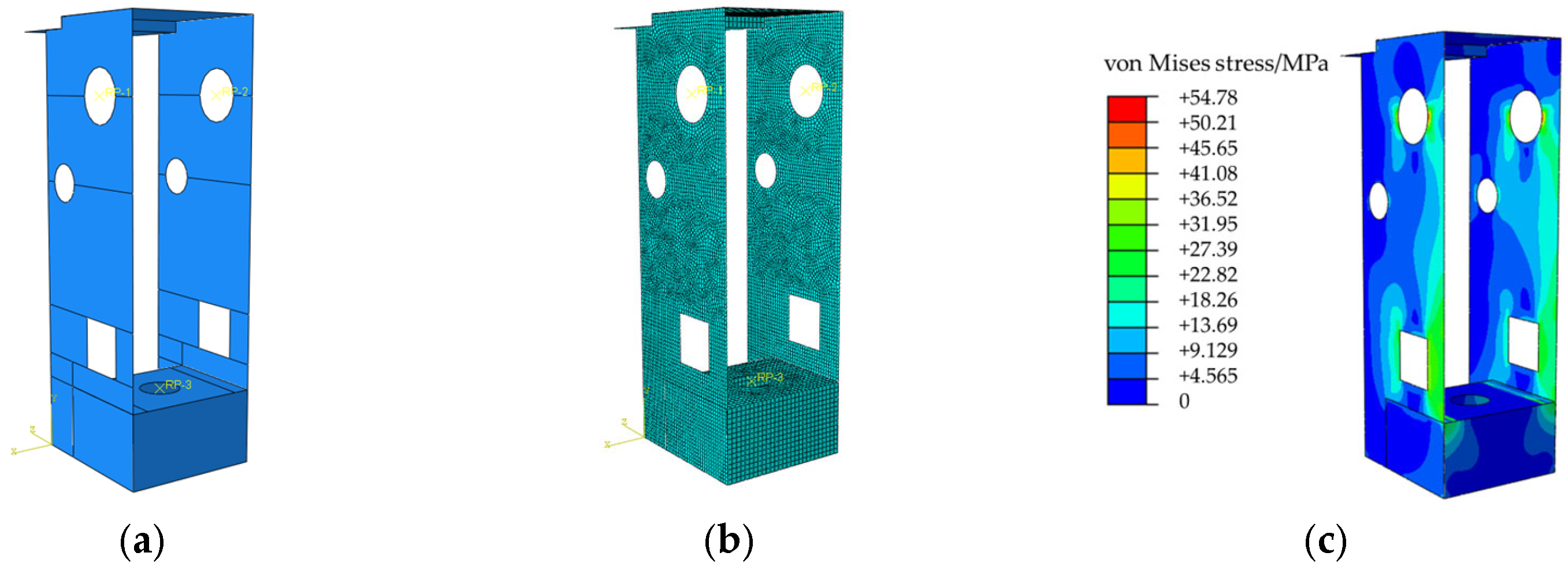
Figure 14a.
During the execution of the program, appropriate meshing is employed to guarantee operational precision while accelerating the program’s processing speed. The resulting mesh for the machine frame shell model is illustrated in
Figure 14b, with a mesh size of 30 mm, resulting in a total of 12,128 mesh elements and 12,722 nodes. In order to enhance the computational accuracy, element performance, and efficiency of the machine frame shell model, it is decided that the quadrilateral reduced integration element is selected. In the field of structural finite element analysis, the quadrilateral reduced integration element is a versatile shell element type with good applicability. When compared to triangular elements, quadrilaterals utilize bilinear interpolation functions, which facilitate enhanced computational accuracy. Furthermore, quadrilateral meshes can incorporate a range of distinctive element algorithms, including reduced integration, assumed strain, and diverse non-conforming algorithms, to augment precision and computational efficiency. The stress analysis result is presented in
Figure 14c. The analysis parameters for the machine frame shell model are set in accordance with
Section 4.1, and a dynamic kinetic analysis is conducted on the shell model. From the stress contour plot of the shell model and the overall displacement of the machine frame, it can be observed that the shell model’s stress is primarily concentrated around the crankshaft support holes and the sides of the square holes. The maximum stress in the machine frame is 54.78 MPa. The formation of the aforementioned deformation occurs at the upper ends of the square holes in the shell model. The crankshaft support holes and the upper front region of the machine frame undergo the greatest displacement. The maximum overall displacement is generally consistent with the analysis results of the solid model.
The absolute values of stress are not directly comparable between the 2D shell model and the 3D solid model, as they handle stress concentration differently. The purpose of the 2D model is to identify regions with high strain energy density (i.e., regions where material is needed) rather than to accurately predict stress values. The optimization is based on the relative comparison of strain energy distribution within the 2D model, and this distribution pattern is effective in guiding material layout. Finally, the validity of the optimized scheme is verified through the 3D model.
5.2. Topological Optimal Design of the Machine Frame
In order to ascertain the topological conceptual configuration of the shell model of the machine frame, a process of structural optimization is undertaken on the press machine frame, based on the principles of HCA impact dynamics. The application of the HCA algorithm for topological optimization of the machine frame shell model results in a correspondence between the cellular elements and the finite elements. The thickness increment of the element is calculated by extracting the element strain energy density. When the element thickness approaches the minimum value, it represents an area devoid of material; conversely, when the element thickness is greater than the minimum value, it represents an area with thickness. The closer the average strain energy density of all elements is to the target strain energy density, the more optimal the stiffness performance of the machine frame is at those elements. The maximum thickness of the shell model’s side wall elements is set to 195 mm, which equates to a volume of each element of 30 × 30 × 195 mm
3. A minimum element thickness of 8 mm was enforced, representing regions where the internal reinforcement is removed, leaving only the constant-thickness outer skin of the frame. In other words, this means the topology of the reinforcements is changed. The circular and square holes shown in
Figure 15a are reserved holes for machine tool operation. The design domain to be optimized is a special-shaped plate component with holes. The average thickness of the structural units in the design domain was set as 67.86 mm to ensure that the volume of the optimized machine frame design domain structure remains consistent with that of the original model. After 35 iterations, the algorithm converges. At this point, the optimal conceptual configuration of the two-dimensional machine frame shell model is obtained by opening the corresponding data file generated by the iteration. This is illustrated in
Figure 15. It is worth noting that HCA is a rule-based local update algorithm with global volume constraints. Its goal is to homogenize the strain energy density while satisfying the constraints, rather than simply minimizing a single objective. The numerical solution method constructed based on the topology optimization formulation in this paper addresses a non-convex mathematical problem. However, the numerical algorithms used to solve this problem (such as the Optimality Criteria method, the Method of Moving Asymptotes, etc.) do not guarantee that each iteration step will yield a strictly “better” solution. The final convergent value represents a balanced state under the given constraints. We can also observe this phenomenon from literature works [
27,
31].
From the conceptual configuration of the machine frame shell model, it can be observed that areas where the element thickness approaches the set minimum of 8 mm are colored blue, while elements thickness close to 195 mm are colored orange. Intermediate thickness parts are displayed in other colors, and the structural regions formed by the solid grid elements are clearly visible in layers, providing a reference for the subsequent orderly optimization of the machine frame support structure. As shown in
Figure 15c, the blue regions, corresponding to a thickness of 8 mm, are considered as void in terms of the reinforcement layout, as this value represents the thickness of the non-removable outer skin of the press frame (see
Figure 4 and
Figure 16). The topological optimization process thus determines the optimal distribution of reinforcement material (shown in red and other colors) within this skin envelope. Therefore, it can be concluded that the model offers a valuable visual representation of the machine frame shell, facilitating the identification of areas requiring further attention. It can be concluded that under the action of transient impact forces, the areas of the structure with a higher density of material distribution are primarily located on both sides of the square hole and the crankshaft support hole, with a minor concentration on the upper side of the square hole and both ends of the side walls. The topological conceptual configuration of the machine frame shell model, obtained through the coupling calculation of the HCA algorithm and Abaqus, represents the force transmission path of the designed structure.
5.3. Size Optimization Based on Optimal Topological Structure
The topological optimization results of the machine frame shell model based on the HCA method represent a conceptual design. By modifying the thickness of the cellular elements in accordance with the magnitude of strain energy, the optimal distribution of materials is achieved, thereby providing designers with a conceptual structure. Subsequently, size optimization and the regularization of support structures within the design domain are carried out based on this conceptual configuration. This process is of particular significance for the overall design of the machine frame structure.
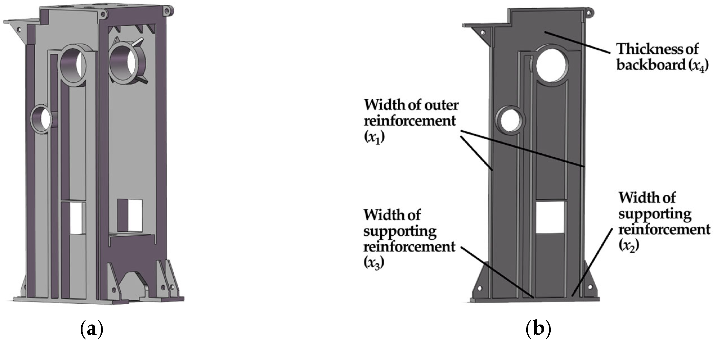
By leveraging the optimized topological conceptual configuration of the machine frame shell model and the stress distribution of the machine frame structure, we revert the machine frame to a three-dimensional solid model for structural modification, as illustrated in
Figure 16a. Support ribs are set up at the locations where material distribution is most dense on both sides of the machine frame’s square hole and cran. The shaft support hole is designated as P2 and P3, respectively, in accordance with the optimal topological configuration. Additionally, support ribs are set at the sides of the machine frame’s design area and the upper end of the square hole, designated as P1. Furthermore, plate thicknesses are set on the front and back sides of the design domain, designated as P4.
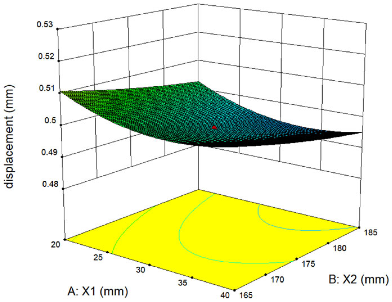
The nonlinear structural optimization iteration process for the machine frame often necessitates intricate calculations and protracted iteration times, which are inimical to both research and application. It is thus imperative to consider more efficacious numerical methods. Optimization strategies of response surface can efficiently approximate the objective function and thus are widely employed in structural size optimization. In this method, the geometric size parameters of the regularized ribbed plate structure are first parameterized, as illustrated in
Figure 16b. The design variable P1 represents the side rib of the machine frame design domain, with width X1; P2 denotes the rib on the right side of the square hole, with width X2; P3 is the rib on the left side. The front and back panels of the machine frame, with thickness X4, are represented by the P4 unit. To ensure that the structural volume in the design domain remains unchanged, the plate thickness X4 is set as a passive variable. The relative deformation displacement between the spatial nodes RP1 and RP3 of the machine frame is chosen as the target variable for the response surface design.
In this numerical experiment, the selection of sample points employs the Central Composite Design (CCD) method, and the range of experimental design variables is presented in
Table 4.
In accordance with the CCD experimental design, an experimental table was constructed comprising the variables. In the 3D modeling software, corresponding machine frame structural solid models were reconstructed based on different experimental parameters and subsequently imported into Abaqus software for explicit dynamic numerical simulation. The relative deformation displacements of the machine frame under different parameter conditions were obtained, and the numerical simulation results are presented in
Table 5.
As the objective function is a weighted sum of multiple scenarios, the response surface design method is employed to perform a weighted sum on the data presented in
Table 5. This process yields the objective function as a second-order polynomial response surface mathematical model for the maximum relative displacement of the frame, as illustrated by the following formula.
The error analysis of the aforementioned response surface fitting results yielded an R
2 value of 0.8713, indicating that the model is an excellent fit for the data. The response surface is depicted in
Figure 17.
The Particle Swarm Optimization (PSO) method is capable of leveraging the structural characteristics of the frame and combining the visualized quadratic polynomial from the response surface to perform global optimization on variable parameters. Consequently, when the mathematical model of the objective function is known to be the aforementioned polynomial, the PSO algorithm can be employed. In order to achieve dynamic optimization of the formula and thereby obtain the global optimal solution for the given optimization problem, the following values are required: x* = [32.63, 183.87, 68.18, 4.97]. At this point, the maximum relative deformation of the frame is 0.4868 mm.
5.4. Transient Dynamic Performance of the Optimal Design
The optimal parameters (
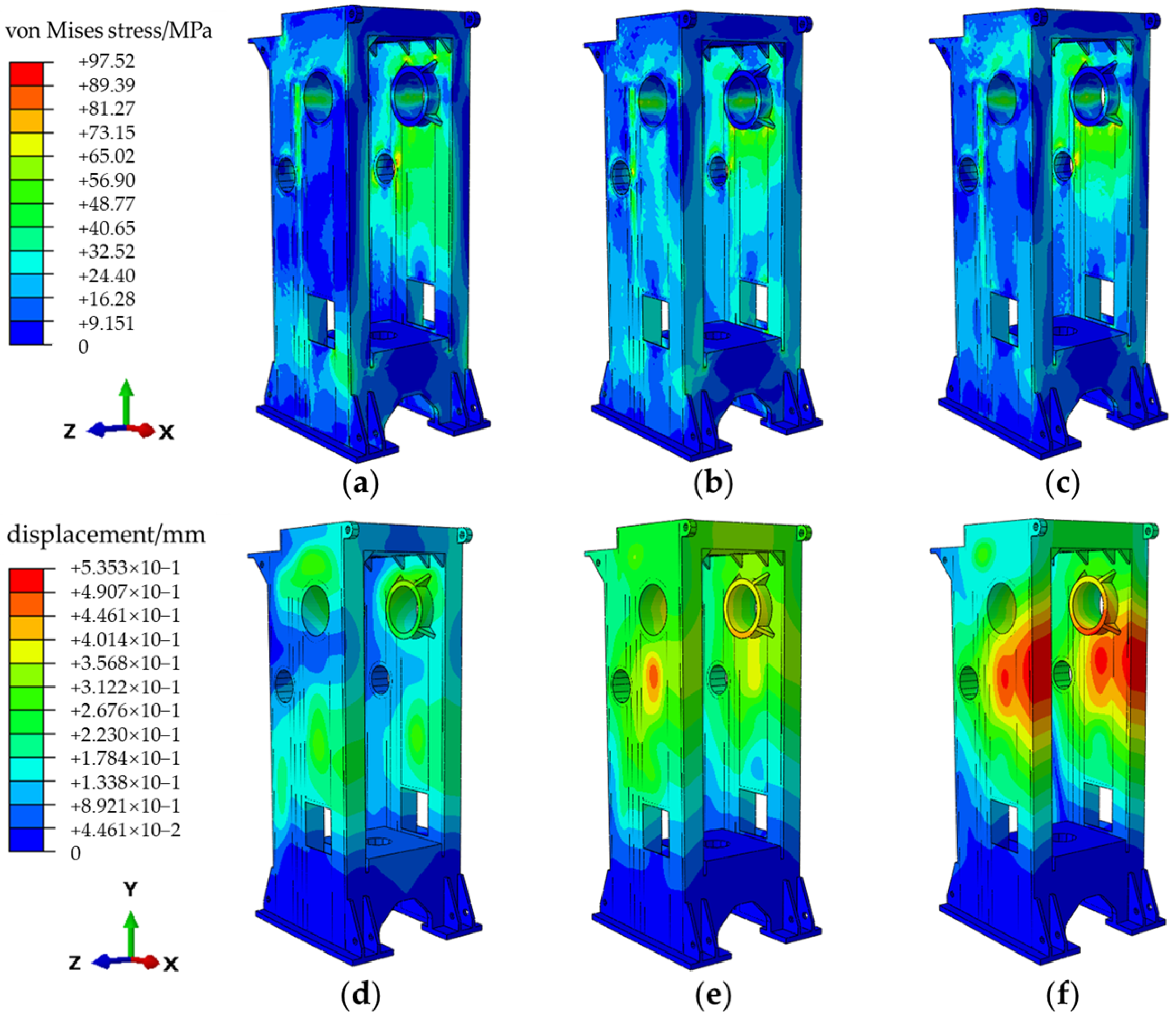
x*) are employed for parametric modeling in SolidWorks, with the 3D model subsequently imported for explicit dynamic analysis. The initial time step of 0.11 s is evenly divided into 20 frames, with three of these selected for plotting the equivalent stress and deformation contours, as illustrated in
Figure 18.
The figure illustrates the maximum equivalent stress and deformation values experienced by the model under load. It can be observed that following optimization, the maximum equivalent stress of the press frame has been reduced to 97.52 MPa, while the overall maximum magnitude displacement of the frame is 0.5353 mm. Both of these values are less than those observed in the original press machine frame.
The explicit dynamic analysis demonstrates that the frame experiences significant vibration and deformation displacement when subjected to transient impact forces. The maximum relative displacement between the crankshaft support hole and the worktable surface occurs during the nominal pressure phase. Consequently, the corresponding relative displacement values are extracted from the analysis results and presented in
Table 6. Modal analysis was performed on the optimized frame model, the results of which are presented in
Table 7.
A comparison of the maximum relative displacement of the press machine frame obtained from size optimization with the value obtained from Particle Swarm Optimization (PSO) revealed a difference of 0.58%, which is insignificant. This confirms that the design variable parameter values obtained by combining the response surface with PSO are reliable.
An overall consideration of explicit dynamic analysis and modal analysis was employed to assess the transient dynamic optimization scheme parameter model. The optimization results indicated that, prior to optimization, stress concentration was observed near the crankshaft hole and the front end of the press machine frame and square hole front end. Following optimization, both the maximum equivalent stress and the total displacement of the frame exhibited a reduction. The relative deformation displacement between the worktable and the support hole is 0.4896 mm, representing a reduction in deformation of 31.02%. This improvement in precision of the frame is a consequence of the optimization process.
Modal analysis verifies that the press machine structure after optimization will not experience resonance phenomena under various workload excitation, thus meeting the practical requirements. However, although the optimized structure shows a significant positive improvement in terms of impact displacement, from the perspective of dynamic characteristics, the fundamental frequency of the structure has decreased, and there are still high-order natural frequencies of the structure around 60 Hz. Although no obvious dynamic failure problems have been found in the current use of the JH31-250 machine tool, this is still a subject worthy of research.
6. Conclusions
The work presented in this paper focuses on the application research of the HCA algorithm. No modifications have been made to the core of the HCA algorithm; instead, it has been applied to the design problems of complex 3D engineering structures. This paper takes the core equipment of the production line, the JH31-250 forging press, as its research object. It analyses and studies the improvement of the press’s structural stiffness and precision under working conditions, and explores the optimization design methods for the press’s frame structure under different working conditions. The main content and conclusions are summarized as follows:
(1) A 3D model of the frame was established based on the main technical parameters of the JH31-250 press and combined with the transient load analysis of the frame structure. Modal analysis revealed that the first-order natural frequency of the frame is 22.21 Hz, which is much greater than the external excitation source of the frame and will not result in resonance. Under the action of transient dynamic forces, the frame experiences intense vibration. Vibration was observed, accompanied by stress fluctuations around the crankshaft hole, the front end of the frame, and the front of the square hole. The maximum equivalent stress experienced by the frame was 117.80 MPa, the maximum overall displacement reached 0.8845 mm, and the relative displacement of the frame was 0.7098 mm. The study of the frame performance characteristics provides a reference for subsequent static and dynamic structural optimization.
(2) Given the significance of transient dynamic stiffness performance in the structural design of presses and the current dearth of research on optimization methods for the transient dynamic impact stiffness of press frames, this paper presents a transient dynamic optimization design of the frame based on the HCA method. The HCA method is successfully employed by transforming the complex 3D structure into a 2D mechanical model. The density and thickness of the cells within the optimization area are varied with strain energy, resulting in a rational distribution of the frame’s unit thickness and the formation of a determined structural image. This process yields a topological conceptual configuration. Based on this result, further work is conducted to reconstruct the three-dimensional solid frame structure in accordance with the conceptual configuration and to combine the response surface with Particle Swarm Optimization (PSO) methods. This approach was employed to complete the transient dynamic structural optimization of the three-dimensional frame. Following optimization, the maximum relative displacement of the frame was reduced to 0.4896 mm, representing a 31.02% reduction in deformation compared to the original model. Therefore, the transient dynamic stiffness of the frame has been enhanced.
A 31.02% reduction in deformation will bring a series of significant and coherent positive impacts to the optimized press structure. First, the most direct benefit is reflected in the leap in machining accuracy and product quality. The relative displacement between the workbench and the crankshaft support hole is a core factor determining the precision of forging parts. A substantial reduction in deformation means that under impact loads, the alignment of the upper and lower dies has been fundamentally improved. This will directly result in smaller workpiece dimensional tolerances and higher consistency, thereby significantly reducing the rate of waste and defective products caused by the machine’s own deformation and providing reliable equipment support for the production of high-precision forgings.
Second, this optimization will greatly extend the service life of key components, especially expensive dies. The improved frame stiffness effectively reduces the eccentric load and misalignment of the dies, allowing them to operate under normal stress conditions, which slows down the rate of wear and impact damage. This not only reduces the frequency of die maintenance and replacement, saving production costs, but also decreases the downtime caused by die replacement, improving the effective working hours of the equipment.
Third, the structural reliability and long-term durability have been substantially enhanced. The maximum equivalent stress of the optimized frame has decreased by approximately 17.2%, which significantly reduces the risk of fatigue cracks under long-term, cyclic impact loads. This enables the press to operate more reliably under harsh working conditions of heavy loads and continuous production, extending the service life of the entire equipment.
Finally, this successful stiffness optimization also lays a foundation for future technological iterations. On the premise that performance is fully guaranteed or even has a surplus, designers can explore lightweight design in subsequent versions—reducing material usage while maintaining the same stiffness to further lower manufacturing costs and equipment operating energy consumption. To sum up, a 31.02% reduction in deformation is far more than just a numerical improvement; it marks a qualitative leap in the dynamic stiffness performance of the press. Ultimately, this translates to higher production efficiency, better product quality, and lower overall operating costs for users, greatly enhancing the market competitiveness of this equipment.
The workflow introduced by this article is an inspiring work. Future research that can be carried out includes:
Multi-objective optimization and consideration of multiple working conditions: Integrate multiple objectives such as lightweight design, fatigue life, and thermal deformation, or take into account dynamic loads under different process conditions.
Optimization considering manufacturing process constraints: Directly introduce process limitations (e.g., welding, casting, or additive manufacturing) into topology optimization to improve the manufacturability of design schemes.
Optimization of dynamic characteristic control: Proactively control the natural frequency and vibration mode of the structure during optimization to avoid resonance with the operating frequency or motor harmonics.
