Article

Development of a Polyurethane Lost Circulation Material Suitable for Malignant Leakage of Drilling Fluid

1
China Oilfield Services Ltd., Binhai, Tianjin 300450, China
2
China University of Petroleum, Beijing 102249, China
*
Author to whom correspondence should be addressed.
Processes 2025, 13(11), 3707; https://doi.org/10.3390/pr13113707
Submission received: 2 November 2025 / Revised: 10 November 2025 / Accepted: 14 November 2025 / Published: 17 November 2025

Abstract

A malignant leakage presents a significant challenge in drilling engineering, particularly within carbonate formations, where such a leakage is frequently encountered. Currently, there is no effective solution to this problem. In this study, a water-reactive polyurethane sealing agent was developed using multifunctional polypropylene glycol and 1,4-butanediol (BDO) as soft segments, diphenylmethane diisocyanate (MDI) as the hard segment, and a composite catalyst consisting of N, N-dimethyl cyclohexylamine (PC-8) and dibutyltin dilaurate (T-12). The material reacts rapidly with water to form a high-strength gel, with the reaction time being controllable. Through experimental optimization, it was determined that the BDO mass fraction was 1%, and the molar ratio of isocyanate group to hydroxyl group was 1.8. Additionally, the gelation time can be controlled by adjusting the mass fraction of the composite catalyst. Experimental results from sand-bed and fracture-plate tests indicated that the material could withstand pressures exceeding 3 MPa at 93 °C and exhibited resistance to saturated NaCl and CaCl2 environments. The plugging mechanism was investigated using scanning electron microscopy (SEM), thermogravimetric analysis (TGA), and Fourier-transform infrared (FTIR) spectroscopy. The results demonstrated that the agent formed a compact, micron-scale porous structure upon reacting with water, exhibiting excellent thermal stability and dual plugging performance through both physical and chemical mechanisms. Due to its water-reactive characteristics, a multi-stage injection process was adopted for field application design. This material shows promising potential for mitigating large-fracture-type malignant leakages in drilling operations.

1. Introduction

As oil and gas exploration expands into deep and ultra-deep reservoirs, unconventional resources, and deep-sea environments, drilling operations face increasingly severe geological challenges and numerous technical bottlenecks. Malignant wellbore leaks rank among the most prevalent and intractable complex events, emerging as a critical constraint on drilling engineering [1,2,3,4,5,6,7]. Carbonate formations are frequent loci of severe losses and readily precipitate secondary complications such as borehole collapse, pipe sticking, and blowouts. Globally, well leakage accounts for approximately 20–25% of all wells, with annual containment and remediation expenditures in the petroleum industry approaching 4.0 × 10⁹ USD [8]. A variety of sealing materials—bridging agents, gels, and curable systems—have been developed worldwide, giving rise to multiple plugging strategies, including bridging plugging [9,10,11,12], gel plugging [13,14,15,16], curable plugging [17,18], and composite-material plugging [19,20]. However, in severely fractured formations with large leakage conduits, conventional sealants are readily diluted and fail to remain in place, causing substantial fluid loss before a competent sealing layer can form. At present, no preventive or rapid-remediation method is broadly effective for such scenarios.
Polyurethane-based plugging agents utilize water as the reaction initiator, exhibiting both water-reactive and rapid-setting behavior. Upon reaching the loss zone and contacting water, they resist dilution and quickly form a high-strength solid, effectively filling leakage channels and adjacent voids and thus offering broad application potential. Isocyanate groups (–NCO) on the polyurethane backbone readily undergo cross-linking with water [21,22], enabling rapid gelation to block flow paths while expanding and adhering to fracture surfaces to achieve durable water shutoff [23]. The setting time can be tuned to operational needs by adjusting the catalyst dosage. Polyurethane systems have been widely formulated as reactive chemical grouts for seepage control in river-crossing tunnels, subways, mines, reservoirs, and other underground structures under ambient temperature and pressure [24,25,26]. Their application to petroleum lost-circulation control has emerged more recently, typically targeting shallow, fissure-type losses. For example, Zhu et al. developed a water-reactive sealing fluid and associated tools for malignant leakage in fracture-borne dynamic-water layers, achieving efficient single-pass sealing of severe return-water losses in the Luohe Formation via glass-fiber-tube injection using ball-drop and press methods [27]. Nevertheless, these implementations are generally limited to shallow formations (<500 m), whereas industry development is increasingly oriented toward deep and ultra-deep wells characterized by high temperatures, strong mineralization, and elevated pressures. To address this gap, the present work develops a deep-well-capable polyurethane leak-sealing agent tailored for drilling operations and proposes a corresponding field construction process.
Consequently, this study formulates a polyurethane lost circulation material using polypropylene glycol (PPG) and 1,4-butanediol (BDO) as soft segments, diphenylmethane diisocyanate (MDI) as the hard segment, and a composite catalyst comprising N, N-dimethyl cyclohexylamine (PC-8) and dibutyltin dilaurate (T-12). Leveraging the water-activated nature of polyurethane sealants, the field procedure is designed to inject the sealant and catalyst solutions separately, with synthesis base oil used as a spacer fluid between them. A multi-stage pumping schedule ensures that the reaction is initiated only upon arrival at the loss zone, thereby minimizing contact with water during placement. Once entering the severely leaking interval, the system reacts with formation water to form a high-strength cementitious layer within narrow fractures and flow channels, thereby achieving effective leak sealing.

2. Materials and Methods

2.1. Materials

PPG with a molecular weight of 500 and 3000, chemical grade, were both procured from Shanghai Titan Scientific Co., Ltd. (Shanghai, China); BDO, chemical grade, was purchased from Beijing InnoChem Science Co., Ltd. (Beijing, China); MDI, chemically pure, was supplied by Shanghai Titan Scientific Co., Ltd. (Shanghai, China); PC-8, chemically pure, was provided by Shanghai Meiruier Biochemical Technology Co., Ltd. (Shanghai, China); T-12, chemically pure, was supplied by Shanghai Meiruier Biochemical Technology Co., Ltd. (Shanghai, China).

2.2. Preparation of Polyurethane Leak Sealing Agent

All glassware, including three-necked flasks, beakers, and ancillary apparatus was dried in an oven at 70 °C for 1 h. Polypropylene glycol PPG-500 and PPG-3000 were mixed at a mass ratio of 3:7 and transferred to a three-necked flask. The system was evacuated to −0.095 MPa, heated to 115 °C, and dehydrated under stirring for 2.5 h. After cooling to 50 °C, the measured amounts of MDI and the composite catalyst were added. The mixture was then heated to 80 °C and allowed to react for 1 h, followed by cooling to ambient temperature to yield the polyurethane plugging agent.

2.3. Performance Test and Mechanism Analysis

Severe-loss conditions with large pores and fractures were simulated using sand beds and fracture plates. Pressure-bearing tests were carried out with a GGS71-A high-temperature, high-pressure (HTHP) water-loss tester (Qingdao Haitongda Special Instrument Co., Ltd., Qingdao, China). After installing the sand bed or fracture plate, the polyurethane plugging agent was introduced into the apparatus and allowed to consolidate in water for 10 h. A bentonite-based slurry was then added for testing at 93 °C, with pressure elevated at 0.2 MPa min−1. Leakage was recorded over time. Each experiment was performed in triplicate, and the mean value was reported when no significant differences were observed.
Following the pressure-bearing protocol, water was replaced with either saturated NaCl or saturated CaCl2 solutions to evaluate performance in highly mineralized environments. Tests were repeated three times, and the mean value was reported when no significant differences were observed.
Compressive and tensile strengths were measured using a WH-5000 universal testing machine (Shanghai Jingqi Instrument Co., Ltd., Shanghai, China). Each test was conducted in triplicate, and the average values were calculated. Dumbbell-shaped specimens with a length 23 mm, a width of 10 mm and a thickness of 10 mm were prepared for tensile testing, and cylindrical specimens with a diameter of 30 mm and a height of 25 mm were prepared for compression testing.
Microstructural observations of consolidated specimens were performed using an SU8010 cold-field-emission scanning electron microscope (SEM, FEI, Hillsboro, OR, USA).
Thermal stability was assessed on a thermogravimetric analyzer (TGA, Mettler Toledo AG, Greifensee, Zurich, Switzerland) from 50 to 600 °C under nitrogen at a heating rate of 10 °C min−1.
Fourier transform infrared spectroscopy (FTIR, FEI, Waltham, MA, USA) spectrum of the consolidated polyurethane were recorded over 400–4000 cm−1 with a spectral resolution of 0.4 cm−1.

3. Results and Discussion

3.1. Synthesis of the Plugging Agent

This study synthesized a polyurethane-based lost-circulation agent for drilling applications via nucleophilic addition reactions. MDI served as the hard segment, whereas PPG and BDO functioned as soft segments; a composite catalyst of PC-8 and T-12 was employed. The synthesis route is shown in Figure 1a. The rigid benzene rings in MDI improve the thermal resistance of the polyurethane. PPG provides the principal backbone, while BDO acts as a chain extender. Both react with MDI to produce an –NCO-terminated prepolymer. The reaction mechanism is depicted in Figure 1b: the terminal –NCO groups of MDI undergo nucleophilic addition with –OH groups on PPG to form urethane linkages (–NH–COO–); remaining –NCO groups subsequently react with additional PPG –OH groups to promote further cross-linking. In parallel, the dihydroxyl functionality of BDO reacts with MDI –NCO groups, extending the polymer chains and increasing molecular weight. An excess of MDI ensures that the resulting prepolymer is capped with –NCO groups. At this stage, the prepolymer chains associate through hydrogen bonding and related intermolecular interactions.
At ambient temperature, orthogonal experiments were conducted to optimize the formation conditions for polyurethane sealing agents, with results presented in Table 1. The formulation was refined by adjusting the ratio of BDO to reactive monomers (n NCO: n OH, defined as R). Excessively high viscosity (exceeding 30,000 mPa·s) causes pumping difficulties and an increased tendency for adhesion to drill pipes. Adding BDO reduces the prepolymer viscosity; incorporating 1% BDO lowered viscosity to 13,518 mPa·s, rep-resenting a 62% reduction compared to the BDO-free formulation. Further increasing the BDO content yielded only marginal viscosity decreases; hence, the BDO dosage was fixed at 1%. A higher R-value indicates greater crosslinking degree within the polyurethane prepolymer, resulting in enhanced gel strength. When the R value increased from 1.6 to 1.8, viscosity rose by 60.7%. Further increasing to 1.8 caused a 102.1% viscosity increase. With increasing R value, the compressive strengths of samples with molar ratios of 1.6, 1.8, and 2.0 after gelation were 6.5 MPa, 9.35 MPa, and 10.32 MPa, respectively. Based on this, the final BDO content was determined to be 1% and the R value 1.8:1.

3.2. Effect of Catalysts on Polyurethane Sealants

Catalysts can be classified as tin catalysts or tertiary amine catalysts. Tin catalysts, such as T-12, coordinate with the oxygen atom of the -NCO group to impart a positive charge to the carbon atom, thereby facilitating reaction with polyols to form urethane bonds. They exhibit strong catalytic activity for the isocyanate–polyol reaction, reducing the synthesis time of polyurethane sealants. Tertiary amine catalysts, such as PC-8, coordinate with the hydrogen of hydroxyl groups to promote urethane formation. They exhibit strong catalytic activity for the isocyanate–water reaction, accelerating the reaction between the polyurethane sealant and water and thereby reducing gelation and setting times. By combining two catalysts and adjusting their ratio, the synthesis time and gelation time of the polyurethane prepolymer can be regulated.
According to the construction process, once the leak-sealing agent reaches the wellbore bottom, it probably intrudes the leaking formation. Given that the pathways for severe fluid loss were typically substantial, it was desirable for the sealing agent to react rapidly within 30 min upon entering the formation, thereby forming a solidified mass. We systematically investigated the effects of T-12 and PC-8 dosage on the catalyst, as detailed in Table 2. T-12 primarily influences polymer synthesis time: at 10% dosage, agglomeration occurs during polymerization, preventing synthesis; at 0.1% dosage, synthesis requires 5 h, which was excessively long; at 1% dosage, synthesis time was 1 h, representing the optimal condition. Setting time may be defined as the duration after the sealant reacts with water during which it can be placed upside down without falling. PC-8 primarily influences the setting time. As its dosage increases, the setting time of the leak-sealing agent progressively decreases, ranging from 3 to 30 min, indicating that the setting time can be tuned by adjusting the PC-8 dosage. At a dosage of 2%, the setting time was 15 min. PC-8 catalyst primarily affects the curing time of polyurethane. To facilitate observation of the reaction process, the catalyst dosage yielding a 15-min setting time was selected for subsequent experiments. Hereafter, a composite catalyst comprising 1% T-12 and 2% PC-8 was employed.

3.3. Effect of Water on Polyurethane Leak Sealing Agents

Water serves as the accelerator for the cross-linking and curing reaction of polyurethane leak-sealing agents. Its influence directly impacts the sealing efficacy within geological formations. Consequently, it was imperative to investigate the effects of water dosage and the presence of saline solutions on the sealing agent.

3.3.1. Effect of Water Content on Setting Time and Setting Strength

Unlike conventional polyurethane applications, the water content within geological strata was inherently variable. Consequently, it was imperative to investigate the reaction behavior of poly-urethane sealing agents under differing moisture levels. Water and polyurethane were blended in the following ratios: 1:9, 2:8, 3:7, 4:6, and 5:5. Experimental results showed that the setting time remained consistently at 20 min across all water-to-polyurethane ratios, with no liquid dripping after inversion. As the ratio increased, the height of the cured polyurethane sealant initially rose before decreasing. The highest height was achieved at a ratio of 2:8. This indicates that at a ratio of 2:8, the hydroxyl groups in water react most completely with the isocyanate groups, producing the greatest volume of carbon di-oxide gas and resulting in the highest cured height. At other ratios, the polyurethane still cements and solidifies, achieving an excellent sealing effect. Consequently, water readily reacts with isocyanate groups. Even with reduced water content, isocyanate and hydroxyl groups can still form urethane groups, subsequently undergoing cross-linking to produce urethane esters. Excess water does not result in insufficient strength of the cured material.

3.3.2. Effect of Saline Water on Leak-Sealing Agents

In practical drilling operations, formation water often possesses a certain degree of mineralization. Consequently, an evaluation of the salt resistance of polyurethane materials was required. Saturated NaCl and CaCl2 solutions were prepared as triggers. Using syringes, experiments assessed the polyurethane prepolymer’s resistance to salinity. Experimental results showed that after adding saturated NaCl and CaCl2 solutions, the polyurethane plugging agent still underwent gelation, forming a consolidated mass. Water dyed with ink was added above the polyurethane and subjected to pressure without leakage occurring. This indicates that NaCl and CaCl2 do not interfere with the reaction between isocyanate and water, allowing normal reaction to produce a solidified mass. Furthermore, the formed solidified mass exhibits excellent pressure-bearing capacity.

3.4. Evaluation of Pressure-Bearing Performance of Polyurethane Sealant

3.4.1. Pressure-Bearing Performance of Polyurethane Leak Sealing Agent

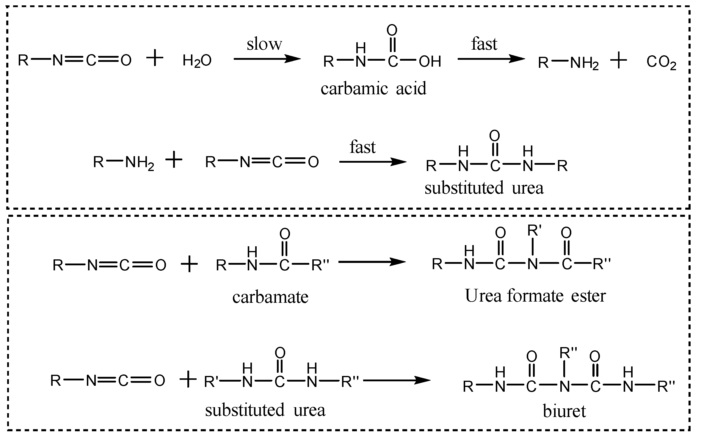
The -NCO groups in polyurethane leak-sealing agent react with water to form substituted urea, which subsequently undergo cross-linking to produce a dense, well-consolidated mass with high compressive strength. Therefore, both sand bed and crack plate tests were employed to evaluate the compressive sealing performance of the sealant. The results were presented in Table 3. The cured layer height of the polyurethane leak-sealing agent after water addition was 10 cm. During curing, the -NCO groups in the sealant reacted with -OH groups in water, initially forming substituted urea and CO2 gas. Excess -NCO groups further reacted with substituted urea to produce biuret, initiating cross-linking reactions that formed a solidified body within the sand bed pores or joint plate gaps. Concurrently, gases generated during the reaction further expand the consolidated mass, ensuring complete sealing of the gaps. A sand bed with a particle size of 10–20 mesh (approximately 0.5~2.0 mm) is primarily used to simulate porous media and microfractured rock formations. The gap plate dimensions are 5 mm, chiefly simulating macro-fractured formations. Under conditions of 93 °C, 10~20 mesh and 20~40 mesh sand beds, and 3 mm and 5 mm slotted plates, the loss volume was 0 mL in all cases, indicating broad applicability and excellent sealing performance. Upon contact with water, the polyurethane plugging agent forms a high-strength, dense consolidated mass capable of effectively sealing pores and fractures. This solidified substance exhibits a pressure-bearing capacity exceeding 3 MPa, demonstrating excellent pressure resistance. PF-SEAL and PF-SZDL are two composite bridging plugging materials, while XZ-APA is an adaptive plugging agent. Evaluated using a 10~20 mesh sand bed and 3 mm gap plates, none could withstand pressures exceeding 3 MPa and ultimately failed completely. In contrast, polyurethane plugging agents demonstrated superior performance, making them promising candidates for plugging severe wellbore leaks. Consequently, it holds promise for addressing severe fluid loss scenarios.

3.4.2. Salinity Resistance of Polyurethane Sealant

We also prepared saturated NaCl and CaCl2 solutions to evaluate the sealing performance of the polyurethane sealant in the presence of salt and calcium ions. The test results are presented in Table 4. The consolidation body formed using saturated NaCl solution as the triggering agent exhibited a volume loss of 3 mL at 93 °C under a 10~20 mesh sand bed. This result indicates that while the saturated NaCl solution slightly affects the consolidation strength, the influence is minimal, and the material remains resistant to saturated salts. In contrast, the consolidation body formed using saturated CaCl2 solution as the trigger showed zero loss under identical conditions, demonstrating no adverse effect on consolidation strength. The resulting consolidation structure demonstrated a pressure resistance exceeding 3 MPa, confirming excellent calcium resistance. Overall, the polyurethane leak-sealing agent exhibits remarkable resistance to both salt and calcium, fully satisfying the requirements for practical applications.

3.5. Evaluation of Mechanical Properties of Polyurethane Leak-Sealing Agent

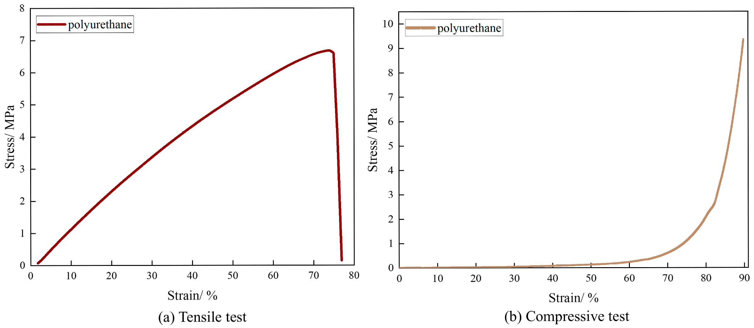
The elongation at break represents the ratio of the specimen’s length at fracture, corresponding to a tensile stress of zero. A high elongation at break reflects the material’s ability to undergo substantial plastic deformation prior to failure, serving as a direct indicator of toughness. Upon water activation, the polyurethane sealant cures into a compact and mechanically robust solid. Accordingly, its mechanical properties were investigated, with the corresponding results shown in Figure 2. In the tensile strength test, the elongation at break reached 76.9%, accompanied by a tensile strength of 6.68 MPa. In the compressive strength test, a deformation of 89.8% corresponded to a compressive strength of 9.35 MPa. These results demonstrate that the cured material exhibits both high strength and toughness, indicating favorable mechanical performance. This conclusion is further supported by the pressure-bearing test results, confirming that the material satisfies the practical requirements for leak sealing applications.

3.5.1. Leak-Sealing Mechanism of Polyurethane Sealant

The polyurethane leak-sealing agent is a chemically setting slurry that reacts upon contact with water, exhibiting several distinct advantages. Containing an excess of –NCO groups, it undergoes a rapid curing reaction with water under the action of a composite catalyst. The resulting gelation process yields an elastic solidified mass characterized by excellent strength and waterproofing properties. Furthermore, the cured material demonstrates outstanding adhesion to concrete, rock, and other substrates, allowing it to firmly anchor within leakage pathways. Compared with conventional polyurethane materials, the developed drilling polyurethane leak-sealing agent is better suited for high-temperature, high-mineralization, and high-pressure environments. The rigid benzene ring structure in MDI enhances the thermal stability of the polyurethane sealant. The consolidated body formed through network cross-linking exhibits high mechanical strength, maintaining effective sealing performance even under elevated formation pressures. The specific reaction mechanism is illustrated in Figure 3. The free –NCO groups in the polyurethane sealing agent first react with water to generate carbamic acid, which is inherently unstable and rapidly decomposes to yield amines and CO2 gas. The excess –NCO groups subsequently react with urethane groups (–NH–C(=O)–) within the polyurethane matrix to form urethane esters, initiating the cross-linking process. Concurrently, the generated urea groups can further react with unreacted –NCO groups to form biuret linkages, leading to additional cross-linking. This extensive network formation produces a consolidated mass with sufficient strength to firmly adhere within leakage channels, thereby achieving a durable and effective sealing effect.

3.5.2. SEM Analysis

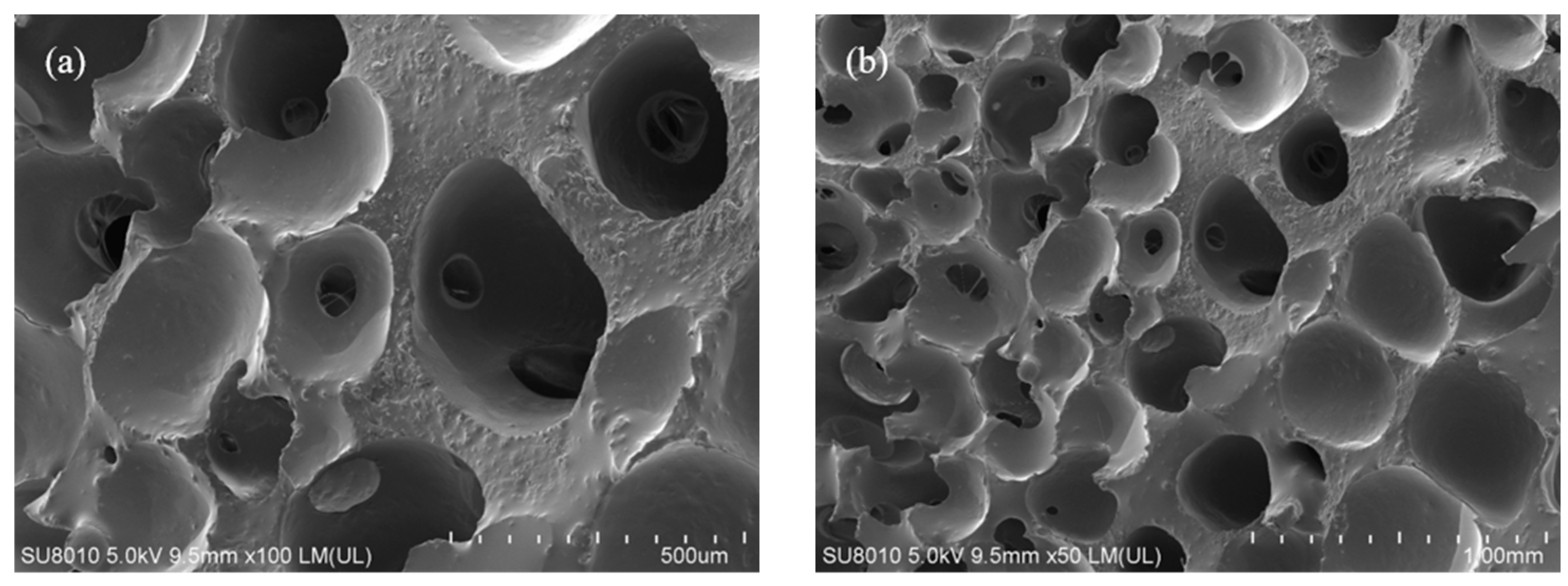
SEM analysis of the solidified mass formed by the polyurethane plugging agent upon contact with water, as shown in Figure 4, distinctly reveals its microstructural characteristics. The polyurethane matrix displays continuous, consolidated morphology composed of approximately circular, closed-cell pores. The average pore diameter ranges from 200 to 300 µm, with a mean variation of about 10 µm, and the pores are uniformly distributed throughout the structure. Notably, no significant interconnected or open pores are observed, indicating a compact and well-consolidated framework containing evenly dispersed, bubble-like cavities. These observations suggest that during the sealing process, the free and terminal –NCO groups in the polyurethane sealant react with water to generate CO2 gas. The resulting gas expansion induces swelling of the consolidated mass, allowing it to effectively fill leakage pathways and achieve physical sealing. Simultaneously, the –NCO groups continue to undergo cross-linking reactions with urethane and substituted urea groups, producing a chemically cross-linked, high-density solidified structure. This dual mechanism, which integrates physical expansion with chemical consolidation, facilitates the formation of a dense and cohesive solidified structure, thereby ensuring durable and highly effective sealing performance.

3.5.3. Thermogravimetric Analysis

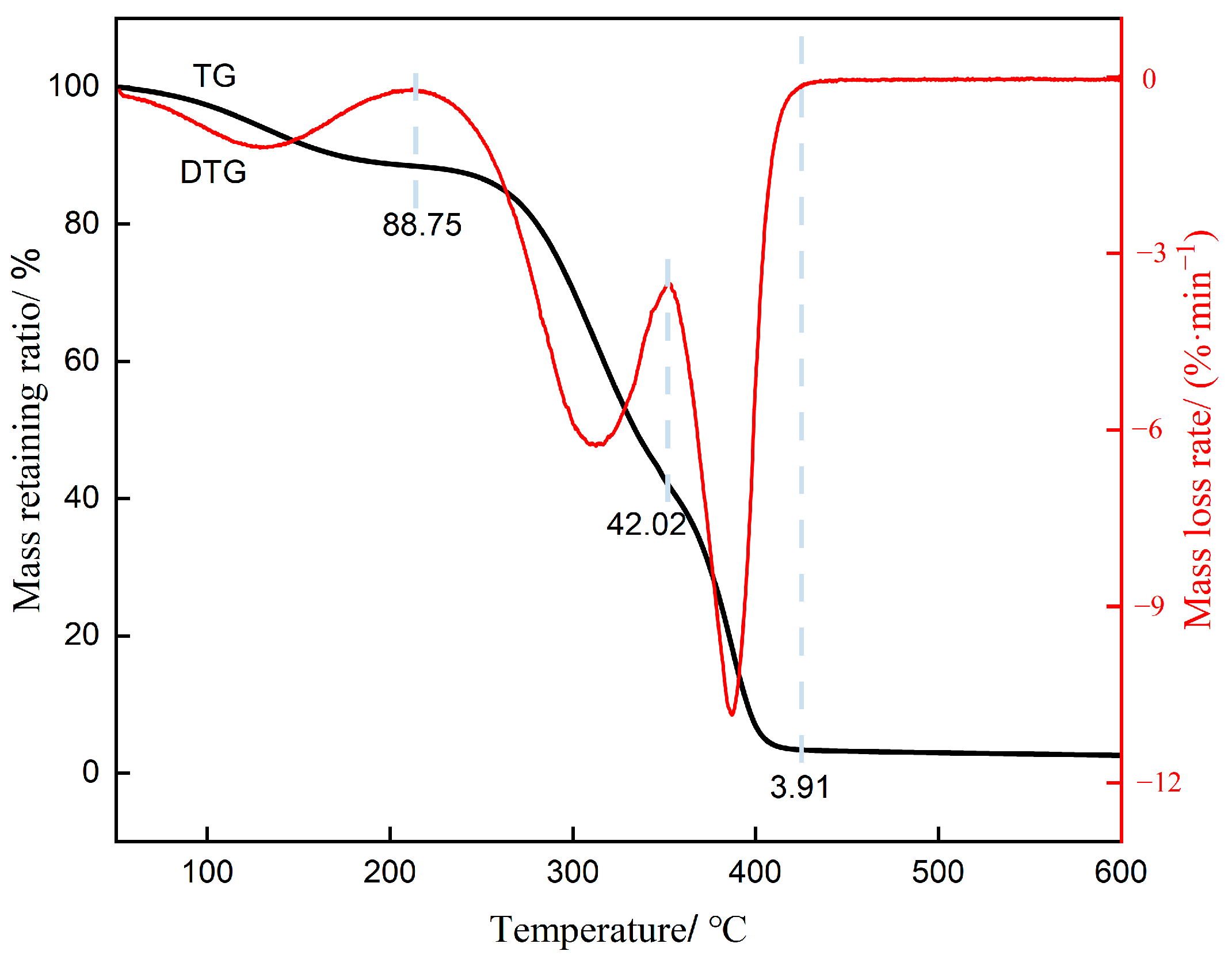
The thermal stability of the consolidated material formed by the reaction between polyurethane and water was evaluated using TGA, and the results are presented in Figure 5. The fluctuations observed in the curve at 100 °C were attributed to water contained within the closed pores of the consolidated material. The thermal degradation of polyurethane materials occurs in two distinct stages: the first stage, between 220 and 350 °C, involves the cleavage and depolymerization of polyurethane and polyurea, yielding decomposition products including isocyanates, polyols, amines, and carbon dioxide; the second stage, occurring between 350 and 500 °C, primarily involves the decomposition of the soft segments, producing carbon dioxide and other by-products. The precise mass loss percentages recorded during the first and second thermal degradation stages were 46.73% and 42.82%, respectively. Consequently, polyurethane materials exhibit desirable thermal stability.

3.5.4. FTIR Analysis

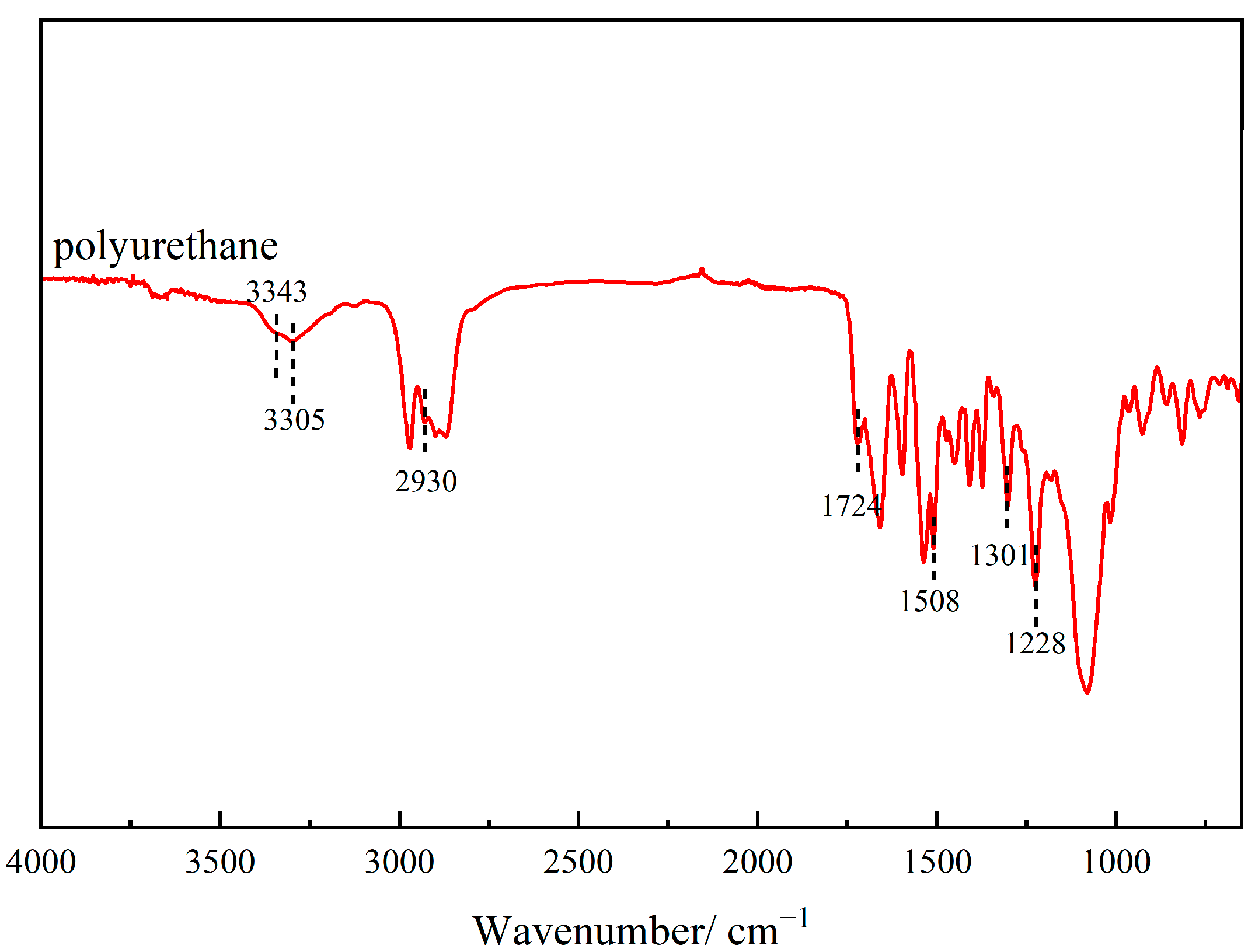
Figure 6 presents the FTIR spectrum of the solidified material formed after the reaction between polyurethane and water. The characteristic absorption peak at 3343 cm−1 corresponds to free N–H groups in the polyurethane material that have not formed hydrogen bonds, while the peak at 3305 cm−1 represents the N–H stretching vibration associated with hydrogen bonding to carbonyl groups. The absorption band at 2930 cm−1 is attributed to the asymmetric stretching vibration of methylene groups, and the peak at 1724 cm−1 corresponds to the characteristic absorption of carbonyl groups. Peaks observed at 1508, 1301, and 1228 cm−1 are assigned to the characteristic absorptions of N–H, C–N, and C–O in urethane bonds, respectively, confirming the formation of urethane linkages during polymerization. Notably, no absorption peak corresponding to the –NCO stretching vibration was detected near 2240 cm−1, indicating that the –NCO groups in the consolidated body had completely reacted, cross-linking with urethane and substituted urea structures to form the solidified network. This observation further substantiates the proposed leak-sealing mechanism of polyurethane.

3.6. Application Process of Polyurethane Sealant

3.6.1. Influence of Water on Application Process

During actual drilling operations, to ensure safety throughout the construction process, the polyurethane sealing compound and catalyst solution are pumped separately. This approach minimizes the influence of water within the wellbore on the sealing compound. In the absence of a catalyst, the effect of water on the sealing agent is summarized in Table 5. Overall, as the water content increases, the setting time gradually decreases. When the temperature increases from 70 °C to 80 °C, the setting time is shortened by approximately 1 h, and when it rises further from 80 °C to 100 °C, the setting time decreases by about 3 h. These results demonstrate that higher temperatures lead to shorter setting time. At lower temperatures, the addition of 50% water reduces the setting time from 7 h to less than 2 h, whereas at higher temperatures, the same water content can decrease the setting time to as little as 20 min. Therefore, in practical plugging operations, contact between the sealing agent and water should be minimized, especially in wellbore environments exceeding 80 °C, where water exposure can trigger rapid solidification. To mitigate this issue, a staged injection application process has been developed to prevent premature reactions upon contact with water.

3.6.2. Application Process Design

As polyurethane sealing agent must not come into contact with water during application, the process has been designed accordingly. Synthesized base oil was used as the isolation fluid, pumped to the wellbore bottom via a staged injection method. Required equipment includes: a dry storage tank capable of internal coating treatment, high-pressure hoses, cementing pump truck, square drums, and synthesized base oil as isolation fluid.
The internally coated storage tank was prepared at the surface; pipelines were connected to the pumping truck, and a pressure test was completed successfully. The drill string (fishtail joint and plain drill pipe) was lowered to the leaking formation, and the wellbore bottom was cleaned as appropriate to ensure exposure of the leaking formation passage. After cleaning the wellbore bottom, two strings of pipe were raised and preparations were made to commence grout pumping. Prior to pumping, approximately 2 m3 of synthesis base fluid was prepared in the cementing pump truck’s water tank as the pre-flush fluid; about 1 m3 of cleaning fluid was reserved in the square drum; and the polyurethane plugging agent was prepared in the internally coated storage tank. The cementing truck first injected the synthesis-based pre-isolation fluid, followed immediately by the polyurethane plugging agent. Subsequently, the synthesis-based isolation fluid, the catalyst solution, and the wash fluid were pumped in sequence. Finally, the fluid was replaced using drilling fluid via a mud pump or the cementing truck. Throughout the process, all pumped fluids were measured meticulously. When the pre-isolation fluid displaced the drill string water eyes, the well was shut in, and the drill string water eyes were completely displaced with a mixture of pre-isolation fluid, polyurethane plugging agent, and cleaning fluid. Upon completion of fluid displacement, the well was opened and the drill string was raised to a safe position for static observation. During drill string recovery, equal-volume grouting or less-than-equal-volume grouting was performed.
After the sealing slurry was allowed to settle for the specified period, circulation testing was conducted at appropriate locations. If necessary, further sealing operations, such as cement plugging, were performed to enhance the pressure-bearing capacity of the leaking formation. Once circulation was largely established, additional settling was allowed until the mixture achieved sufficient compressive strength through reaction. Following successful sealing, a low-pressure cutting mode was employed to clear any consolidated material within the wellbore. Excessive reaming speed was avoided to prevent inadequate fragmentation, which could cause large fragments to return to the upper small borehole and jam the drill string. Reaming debris did not adversely affect the drilling fluid and was removed using solids-control equipment such as vibrating screens.

4. Conclusions

(1)
A water-reactive polyurethane grouting material was synthesized using PPG and BDO as soft segments, MDI as the hard segment, and a composite catalyst system composed of PC-8 and T-12. The polyurethane was synthesized at an –NCO/–OH molar ratio of 1.8, 1 wt% BDO, and a 3 wt% composite catalyst, a polyurethane sealant exhibiting controllable gelation time and high mechanical strength, was obtained.
(2)
FTIR spectroscopy confirmed the formation of urethane linkages, verifying the successful polymerization reaction. SEM revealed that the cured polyurethane exhibited a dense and continuous microstructure, while TGA demonstrated excellent thermal stability.
(3)
The polyurethane lost circulation material was capable of setting and hardening in aqueous environments of various concentrations without alteration of its gelation behavior. It effectively sealed 10~20-mesh sand beds and 5 mm crack plates under pressures exceeding 3 MPa, thereby controlling severe fluid losses. Moreover, the cured polyurethane could maintain integrity and pressure resistance in saturated NaCl and CaCl2 solutions, exhibiting outstanding resistance to salinity interference.
(4)
The primary sealing mechanism of the polyurethane lost circulation material lies in its interaction with formation water. Upon contact with water, the -NCO groups in the polyurethane react with water, carbamates, and the substituted urea group, leading to rapid crosslinking and curing. This process forms a high-strength cemented layer that effectively seals leakage channels. Moreover, during the curing process, the material undergoes volumetric expansion, filling voids within the loss zone. Consequently, dual sealing is achieved through both cementation and expansion mechanisms.
(5)
Considering the strong water reactivity of the polyurethane lost circulation material, its sensitivity to aqueous environments during field application was thoroughly investigated to optimize operational techniques. In practical leak-sealing operations, synthesized base oil was employed as an isolating medium. The downhole injection sequence consisted of an isolation fluid, a polyurethane sealant, an isolation fluid, a catalyst solution, and subsequently a flushing fluid. Throughout this process, exposure of the sealant to water was minimized to ensure controlled gelation and optimal sealing performance.

Author Contributions

Conceptualization, L.Y.; methodology, L.Y.; validation, J.W. and S.H.; formal analysis, X.L., J.W. and S.H.; investigation, J.W., S.H. and L.Y.; resources, L.Y.; writing—original draft, J.W.; writing—review & editing, J.H., G.H. and S.H.; supervision, L.Y.; project administration, X.L., J.H. and G.H.; funding acquisition, X.L., J.H. and G.H. All authors have read and agreed to the published version of the manuscript.

Funding

This research was funded by China Oilfield Services Ltd. (Project No.: HX20240669).

Data Availability Statement

The original contributions presented in this study are included in the article. Further inquiries can be directed to the corresponding author.

Conflicts of Interest

Authors Xiaodong Liu, Jinjun Hu and Guoxin He were employed by the company China Oilfield Services Ltd. The remaining authors declare that the research was conducted in the absence of any commercial or financial relationships that could be construed as a potential conflict of interest.

Abbreviations

PPGPolypropylene glycol
BDO1,4-butanediol
MDIDiphenylmethane diisocyanate
PC-8N, N- dimethylcyclohexylamine
T-12Dibutyltin dilaurate
RThe ratio of isocyanate group to hydroxyl group
FLFilter loss
SEMScanning electron microscopy
TGAThermogravimetric analysis
FTIRFourier-transform infrared

References

  1. Zhang, D.Q. The Technology of Interval Push Clay-Cement Slurry to Lost Circulation in Water Bearing Formation. Drill. Fluid Complet. Fluid 2022, 39, 87–91. [Google Scholar] [CrossRef]
  2. Hou, G.Z.; Xu, J.; Tao, L.; Zhu, G.W.; Su, J.; Chen, K. Research on Combined Chemical and Physical Leakage Plugging Technology in Complex Leakage Formations in Bozhong Oilfield. Contemp. Chem. Ind. 2024, 53, 1959–1965. [Google Scholar] [CrossRef]
  3. Wang, Z.H. The Status and Development Direction of Plugging Technology for Complex Formation Lost Circulation. Sino-Glob. Energy 2014, 19, 39–48. [Google Scholar]
  4. Sum, J.S.; Zang, X.W. Situations, Challenges, Demands and Trends of Drilling Fluid Technology. Drill. Fluid Complet. Fluid 2011, 28, 67–76. [Google Scholar]
  5. Xu, C.Y.; Yan, X.P.; Kang, Y.L.; You, L.J.; Zhang, J.Y. Structural failure mechanism and strengthening method of plugging zone in deep naturally fractured reservoirs. Pet. Explor. Dev. 2020, 47, 399–408. [Google Scholar] [CrossRef]
  6. Li, J.F. The status and development direction of plugging technology for severe circulation loss formation. Explor. Eng. Rock Soil Drill. Tunneling 2019, 46, 19–27. [Google Scholar]
  7. Liu, F.B.; Yin, D.; Wei, T.X.; Wu, H.Y.; Wang, Z.W. Settling Plugging Technology for Severe Lost Circulation at the Salt Bottom of Tarim Piedmont Zone. Xinjiang Oil Gas 2024, 20, 1–7. [Google Scholar]
  8. Feng, Y.; Gray, K.E. Review of Fundamental Studies on Lost Circulation and Wellbore Strengthening; Springer: Cham, Switzerland, 2018; pp. 15–18. [Google Scholar] [CrossRef]
  9. Sun, J.S.; Bai, Y.R.; Cheng, R.C.; Lu, K.H.; Liu, F.; Feng, J.; Lei, S.F.; Zhang, J.; Hao, H.J. Research progress and prospect of plugging technologies for fractured formation with severe lost circulation. Pet. Explor. Dev. 2021, 48, 630–638. [Google Scholar] [CrossRef]
  10. Wang, K. Application Study of Magnesium Aluminum Silicate and Graphene Oxide Layered Nano-Materials in Water-Based Drilling Fluids; China University of Petroleum, Beijing: Beijing, China, 2021. [Google Scholar]
  11. Wang, H.H. Research and Application of Plugging Drilling Fluid System in Zhenjing and Hangjinqi Oil and Gas Field; China University of Petroleum, Huadong: Qingdao, China, 2020. [Google Scholar]
  12. Zhang, P.Y. Progressive Bridge Plugging Technology for Lost Circulation. Drill. Fluid Complet. Fluid 2010, 27, 67–69+92–93. [Google Scholar]
  13. Wang, B. Development of Temperature Sensitive Gel and Study on Plugging Mechanism in Fractures; China University of Petroleum, Huadong: Qingdao, China, 2022. [Google Scholar]
  14. Hu, P.B.; Li, C.K.; Qiao, Y.S.; Jing, R.L.; Wang, Y.D. Research Progress on Application of Polymer Gel Plugging Materials in Petroleum Engineering. Guangzhou Chem. Ind. 2024, 52, 14–16+59. [Google Scholar]
  15. Lin, M.; Zhang, G.; Hua, Z.; Zhao, Q.; Sun, F. Conformation and plugging properties of crosslinked polymer microspheres for profile control. Colloids Surf. A Physicochem. Eng. Asp. 2015, 477, 49–54. [Google Scholar] [CrossRef]
  16. Shi, X.; Yue, X. Migration and plugging mechanisms of self-aggregated microspheres as a novel profile control. J. Pet. Sci. Eng. 2020, 184, 106458. [Google Scholar] [CrossRef]
  17. Yuan, X.Q. Study on the Formula of Rapid Filtration Solidification Plugging; China University of Petroleum, Beijing: Beijing, China, 2023. [Google Scholar]
  18. Chen, N.; Deng, K.; Chen, X.R.; Zhu, M.M.; Yang, Y.; Liu, Z.X. Research and application of curable plugging technology in Changqing Oilfield. China Pet. Chem. Stand. Qual. 2021, 41, 157–159. [Google Scholar] [CrossRef]
  19. Liu, J.H.; Liu, S.H.; Long, D.Q.; Chen, Z.W.; Jin, R.H. Strengthening Plugging Operations by Combining Cross-Linked Film and Chemical Consolidation in Well Ming-1. Pet. Drill. Tech. 2017, 45, 54–60. [Google Scholar] [CrossRef]
  20. Han, C.; Luo, M.; Yang, Y.H.; Liu, X.Y.; Li, W.T. Key drilling technologies for HTHP wells with narrow safety density window in the Yingqiong Basin. Oil Drill. Prod. Technol. 2019, 41, 568–572. [Google Scholar]
  21. Liu, Y.T.; Sun, D.W.; Ran, Q.P.; Lu, L.Q.; Li, B.; Yin, H. Preparation and Performance Study on High Performance Water Reactive Polyurethane Grouting Material. China Build. Waterproofing 2015, 11–14. [Google Scholar] [CrossRef]
  22. Gai, B.W.; Duan, H.T.; Jiang, Y.; Lu, Y.; Jiang, Z.G.; Yao, M.; Dun, Y.C. Development of environmentally friendly hydrophilic polyurethane sealant. New Chem. Mater. 2024, 52, 224–227. [Google Scholar]
  23. Li, X.L.; Peng, C.; Ao, Y.N.; Hao, M.M.; Zhong, Y.H.; Zhang, B. Impact of Composition Ratio on the Expansion Behavior of Polyurethane Grout. Materials 2024, 17, 1835. [Google Scholar] [CrossRef] [PubMed]
  24. Feng, L. Synthesis of Water Soluble Polyether Polyols and Preparation of Polyurethane Grouting Materials; Lanzhou University: Lanzhou, China, 2023. [Google Scholar]
  25. Li, L.; Li, W.; Ou, Y.W. Application of a Fast-swelling Gel Lost Circulation Material in Shale Gas Drilling in Block Changning. Drill. Fluid Complet. Fluid 2019, 36, 181–188. [Google Scholar]
  26. Duan, H.T. Synthesis and Application of Environmentally Friendly Water-Based Sealing Agent; Beijing University of Chemical Technology: Beijing, China, 2022. [Google Scholar]
  27. Zhu, M.M.; Sun, H.; Sun, Y.; Cong, C.; Shi, D.Y.; Jia, J.G. Loss Circulation Control Technology for Malignant Water Leakage Layer in Longdong Tight Oil Region. Pet. Drill. Tech. 2023, 51, 50–56. [Google Scholar] [CrossRef]
Figure 1. Synthesis of the polyurethane plugging agent (a) Synthesis route and (b) Reaction of isocyanate with hydroxyl group.
Processes 13 03707 g001
Figure 2. Mechanical properties (a) tensile test and (b) compressive test of consolidation product of polyurethane.
Processes 13 03707 g002
Figure 3. Reaction mechanism of polyurethane plugging agent in water.
Processes 13 03707 g003
Figure 4. SEM images of polyurethane consolidation structure at different magnifications (a) 300× (b) 150×.
Processes 13 03707 g004
Figure 5. TG and DTG curves of polyurethane concretion.
Processes 13 03707 g005
Figure 6. FTIR spectrum of polyurethane consolidation sample.
Processes 13 03707 g006
Table 1. Optimal parameters and dosages for polyurethane plugging agent.
NumberBDO (%)RViscosity (mPa·s)Compressive Strength/(MPa)
101.6:135,6926.88
211.6:113,5186.55
321.6:111,6346.50
411.8:121,7319.35
512.0:143,91010.32
Table 2. Effect of catalyst dosage on synthesis and setting time.
NumberT-12 (%)PC-8 (%)Synthesis
Time (h)
Gel Time (min)
1101--
20.11530 ± 0.6
311125 ± 0.6
412115 ± 0.3
51315 ± 0.1
61513 ± 0.05
Table 3. Pressure-bearing performance test of sealing agent.
Test
Conditions
TypeTemperature (°C)FL1 MPa
(mL)
FL2 MPa
(mL)
FL3 MPa
(mL)
sand bed (20~40)Polyurethane Sealant93000
sand bed (10~20)Polyurethane Sealant93000
crack plate (3 mm)Polyurethane Sealant93000
crack plate (5 mm)Polyurethane Sealant93000
sand bed (10~20)PF-SEAL9350Complete leakageComplete leakage
crack plate (3 mm)PF-SEAL93Complete leakageComplete leakageComplete leakage
sand bed (10~20)PF-SZDL9360Complete leakageComplete leakage
crack plate (3 mm)PF-SZDL93132Complete leakageComplete leakage
sand bed (10~20)XZ-APA93Complete leakageComplete leakageComplete leakage
crack plate (3 mm)XZ-APA9396Complete leakageComplete leakage
Table 4. Salt and calcium resistance test of sealing agent.
Triggering AgentTemperature (°C)Height of Consolidation Body (cm)FL1 MPa
(mL)
FL2 MPa
(mL)
FL3 MPa
(mL)
Saturated NaCl9310003
Saturated CaCl2000
Table 5. Effect of water content on sealing agent.
Temperature (°C)Water Addition Percentage (%)Gel Time (h)
7007
70203
70502
8006
80201.5
80501
10003
100200.5
100500.33
Disclaimer/Publisher’s Note: The statements, opinions and data contained in all publications are solely those of the individual author(s) and contributor(s) and not of MDPI and/or the editor(s). MDPI and/or the editor(s) disclaim responsibility for any injury to people or property resulting from any ideas, methods, instructions or products referred to in the content.