Abstract
CO2 huff-and-puff in horizontal wells is a key technique for enhancing oil production and improving recovery in tight oil reservoirs. It offers dual benefits: supplementing reservoir energy and promoting carbon sequestration, aligning with the green, low-carbon direction of energy development. However, the overall development performance of such reservoirs is often unsatisfactory. The fundamental reason lies in the strong heterogeneity of tight formations, which leads to uneven fluid intake along horizontal sections. CO2 tends to preferentially channel into high-permeability zones, severely limiting its sweep volume and resulting in the poor recovery of remaining oil in low-permeability areas. This study innovatively proposes a segmented CO2 huff-and-puff approach for horizontal wells. Using two real wells (H1 and H2), numerical simulations were conducted to compare the performance of conventional uniform injection and segmented injection. This study also examined how different segmental injection sequences (heel–middle–toe vs. toe–middle–heel) and injection rates affect CO2 huff-and-puff efficiency. Results show that, compared to uniform huff-and-puff, segmented huff-and-puff improved the oil recovery factor by an absolute value of more than 3.58% in both wells and reduced the average water cut by 4.67%. Among sequencing strategies, the toe–middle–heel injection sequence yielded the best performance, with oil production at the toe increasing by up to 53.64%. Additionally, high injection rates (6 m3/min) significantly expanded the CO2 diffusion range and enhanced its interaction with crude oil. This work proposes a new technique to expand the sweep range and improve production in long horizontal wells within highly heterogeneous tight reservoirs, contributing significantly to more uniform reservoir utilization and enhanced recovery.
1. Introduction
Tight oil reservoirs are a crucial area for future petroleum exploration and development in China. However, these reservoirs are characterized by extremely low porosity and permeability, complex pore structures with an abundant distribution of nanopores [1], and widespread natural fractures, resulting in strong reservoir heterogeneity. These features pose significant challenges to efficient development efforts [2]. Numerous field practices and theoretical studies have demonstrated that CO2 huff-and-puff in horizontal wells is one of the more effective development strategies [3,4,5]. Compared with traditional water flooding, CO2 huff-and-puff in horizontal wells offers several advantages, including crude oil swelling, viscosity reduction, and light hydrocarbon extraction, all of which not only contribute to enhanced oil production in tight reservoirs [6] but also can promote carbon sequestration and bring environmental benefits. Currently, in China, pilot applications have been conducted in heavy oil and low-permeability formations, such as in Liaohe Oilfield and Jidong Oilfield, achieving some success [7]. Internationally, the implementation of CO2 huff-and-puff in Indonesia’s Jatibarang Oilfield has achieved an 86% increase in crude oil production [8], while large-volume CO2 huff-and-puff in horizontal wells has proven effective in U.S. plays like the Eagle Ford Shale and the East Nesson field with gas–water alternating huff-and-puff. However, when it comes to tight oil reservoirs, field applications of horizontal well CO2 huff-and-puff have generally shown poor performance.
At present, the main strategy to improve CO2 huff-and-puff performance in horizontal wells is to enhance the interaction between CO2 and crude oil, thereby improving displacement efficiency. Many researchers have explored the effects of miscibility pressure and CO2 injection parameters on oil recovery through numerical simulations and laboratory experiments. For instance, Huang Xing et al. [9] investigated how injection pressure affects oil recovery in micro- and nanopores, finding that higher pressure lowers the minimum pore size that CO2 can access, significantly increasing its sweep volume. Lang Dongjiang et al. [10] studied the impact of injection conditions and fracture dimensions, identifying pressure differential and diffusion as the main driving forces for CO2 to penetrate the core. Zhang et al. [11], using molecular dynamics (MD), explained the microscopic nucleation and growth of CO2 bubbles in heavy oil systems, showing that a high pressure drop rate can reduce bubble point pressure, enhancing CO2 bubble formation and diffusion, thus improving oil recovery. Jiang Junshuai et al. [12] proposed the concept of the effective interaction radius of CO2, highlighting the injection rate and diffusion coefficient as key factors. Ma Quanzheng [13] and Tang Xiang [14] conducted 3D physical simulation experiments of CO2 huff-and-puff to analyze how cycle time, production pressure, permeability, injection volume, production rate, and soaking time affect recovery, discovering a logarithmic decline in the recovery rate with increasing huff-and-puff cycles. Abedini et al. [15] found that when the minimum miscibility pressure (MMP) is reached, CO2 achieves optimal swelling and significantly reduces interfacial tension, maximizing oil recovery. Hou Guang [16] and Liu Gang [17] optimized key huff-and-puff parameters—total CO2 volume, injection rate, and injection method—and confirmed that CO2 swelling and viscosity reduction are the dominant mechanisms for recovery enhancement. Liu et al. [18] showed via lab tests that the CO2 diffusion coefficient is a critical factor affecting incremental oil production. Abedini Ali et al. [19] identified an MMP of approximately 9.18 MPa, noting diminishing returns on recovery when injection pressure exceeds a certain threshold. Li et al. [20] demonstrated through experiments and simulation that CO2 greatly reduces oil viscosity, with molecular diffusion playing a significant role. Perera et al. [21] observed that the gas injection rate and injection location significantly influence huff-and-puff performance. Talebian et al. [22] found that high injection rates help maintain reservoir pressure but may accelerate gas breakthrough. Rezaei et al. [23] highlighted how density/viscosity differences between CO2 and oil lead to gravity segregation and viscous fingering, which reduce displacement efficiency. Hao et al. [24] found that increasing CO2 injection pressure alters the wetting state from oil-wet to water-wet and enhances crude oil mobility. Chen et al. [25] developed a compositional model to simulate CO2 huff-and-puff and found that greater heterogeneity in shale oil reservoirs results in lower recovery. Orozco et al. [26] performed history matching on Eagle Ford field data and predicted that increasing CO2 injection volumes can significantly improve recovery. Gamadi T.D. et al. [27] simulated CO2 huff-and-puff using a multistage fractured horizontal well model, revealing that while recovery improved after CO2 injection, heterogeneous reservoirs outperformed homogeneous ones in terms of recovery gains. Elturki et al. [28] experimentally concluded that while CO2 flooding in unconventional reservoirs can enhance recovery through multiphase flow, it exacerbates bituminous deposition, leading to pore blockage and increased oil wetness of the system. Key parameters influencing its effectiveness require clarification. Chen Hao [29] proposed a supercritical CO2 composite fracturing method. By generating complex fracture networks with SC-CO2 pre-fluid and combining guanidine-based sand-carrying fluid to support extended fractures, experiments demonstrated significant improvements in fracture complexity and width. Recent studies have shown that integrating intelligent modeling with reservoir characterization can improve prediction accuracy in complex and heterogeneous formations. For example, Moosavi et al. [30] and Mehrabi et al. [31] demonstrated that hybrid data-driven models effectively capture nonlinear relationships between pore structure, heterogeneity, and fluid behavior, providing new insights for optimizing CO2 EOR processes in tight reservoirs. Despite these advancements, most current studies focus on optimizing CO2 injection parameters and improving oil recovery, yet these methods fail to fundamentally resolve the issues of low sweep efficiency and uneven utilization of residual oil in tight oil development.
To address the issue of non-uniform CO2 sweep caused by uneven fluid intake along horizontal well sections in tight reservoirs, this study proposes a segmented CO2 huff-and-puff development strategy for horizontal wells. In conventional CO2 huff-and-puff, CO2 preferentially flows into zones with better reservoir quality and lower flow resistance—commonly referred to as high-permeability segments or “sweet spots”—forming dominant flow channels and rapidly breaking through, which severely limits the sweep range. As a result, CO2 fails to displace oil efficiently in low-permeability or poorer-quality segments, leading to highly uneven sweep efficiency and non-uniform reservoir utilization. The segmented CO2 huff-and-puff approach, by enabling independent injection control in each segment, fundamentally prevents ineffective CO2 channeling through high-permeability zones. It forces CO2 to enter and interact with previously unswept, low-permeability segments, significantly increasing overall sweep efficiency, promoting more uniform reservoir utilization, and mitigating the impact of heterogeneity. This ensures effective development across all segments while controlling water cut. Additionally, high-rate segmented CO2 injection enables effective energy enhancement in low-permeability segments, allowing productive stimulation of tight horizontal well reservoirs.
In response to the non-uniform fluid production in horizontal wells of tight oil reservoirs (Figure 1a), this study innovatively proposes the concept of segmented CO2 huff-and-puff to expand the CO2 sweep range. Compared with conventional uniform CO2 huff-and-puff development in horizontal wells, segmented CO2 huff-and-puff can expand the CO2 sweep volume and thereby mitigate the adverse effects of reservoir heterogeneity (Figure 1b). Firstly, the specific parameter settings for segmented huff-and-puff in horizontal wells are established. The influence of different injection rates and injection sequences is analyzed to quantify how conventional undifferentiated development of tight shale reservoirs leads to uneven recovery of remaining oil across horizontal well segments.
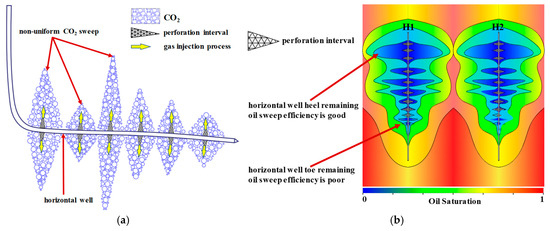
Figure 1.
Uneven CO2 sweep along horizontal wells leads to uneven oil recovery. (a) Non-uniform CO2 huff-and-puff sweep due to undifferentiated horizontal well development; (b) uneven distribution of oil saturation utilization under undifferentiated huff-and-puff.
Furthermore, the root cause of how segmented huff-and-puff effectively mobilizes residual oil at the toe of the well is analyzed in depth, along with the limitations caused by undifferentiated CO2 injection. This study evaluates the impact of various segmental injection sequences on the effectiveness of CO2 huff-and-puff in horizontal wells, revealing patterns in residual oil recovery efficiency across different sequences. It also clarifies the mechanism through which high-rate CO2 injection improves tight reservoir development efficiency. By adopting a segmented huff-and-puff sequence from the toe–middle–heel of horizontal wells and implementing high-rate CO2 injection, the oil recovery factor of tight reservoirs is expected to be enhanced. This research achieves optimization of the key process parameters for segmented huff-and-puff and offers a promising technical route for the efficient development of complex, highly heterogeneous tight oil reservoirs.
2. Segmented CO2 Huff-and-Puff Strategy for Horizontal Wells in Tight Reservoirs
2.1. Proposal of the Segmented Huff-and-Puff Concept
In CO2 huff-and-puff development of tight shale oil reservoirs using horizontal wells, a long horizontal section is typically subjected to undifferentiated (uniform) injection (Figure 2a). During the CO2 injection phase of undifferentiated huff-and-puff, all perforated segments of the horizontal well are opened simultaneously. Due to strong heterogeneity in reservoir properties, CO2 tends to concentrate near the heel (the section closest to the wellbore), as illustrated in Figure 2b. This leads to uneven production from different perforated sections along the horizontal well and causes large disparities in oil recovery performance across segments. Typically, only the heel section achieves effective development, while the middle and toe sections—especially the farther ones from the wellhead—exhibit poor oil recovery.
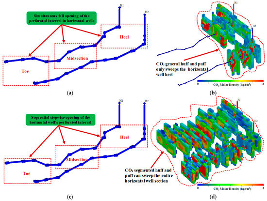
Figure 2.
Segmented throughput schematic diagram. (a) Schematic of segmented CO2 injection sequence; (b) schematic of general CO2 injection sequence; (c) general CO2 injection primarily distributed at the tail end of horizontal wells; (d) segmented CO2 injection enables more uniform CO2 distribution.
2.2. Design of Segmented Huff-and-Puff Scheme and Parameter Settings
To compare the effectiveness of CO2 huff-and-puff under different operational modes, optimize the engineering approach for horizontal well CO2 injection, minimize the impact of heterogeneity in tight shale reservoirs, and achieve efficient development of long horizontal well sections, two types of CO2 huff-and-puff schemes were designed: Undifferentiated (uniform) huff-and-puff, where CO2 is injected uniformly along the entire horizontal section; segmented huff-and-puff, where the horizontal well is divided into three segments based on reservoir heterogeneity characteristics and CO2 is injected into each segment sequentially. These two modes are compared to assess the effect of segmental CO2 injection (Figure 2b). To evaluate the influence of the injection sequence in segmented huff-and-puff, two sequences were designed.
- (1)
- Toe–Middle–Heel: CO2 is first injected into the toe section, then the middle section, and finally the heel section.
- (2)
- Heel–Middle–Toe: CO2 is first injected into the heel section, followed by the middle, and finally the toe section.
These sequences are used to investigate how different segmental injection orders affect the performance of CO2 huff-and-puff in horizontal wells. Additionally, to explore the impact of the injection rate, two scenarios were designed: High-rate injection: 6 m3/min and low-rate injection: 0.1 m3/min.
The specific parameters of these schemes are summarized in Table 1. Six different schemes were used to compare the effects of the following: (1) Injection mode: undifferentiated vs. segmented; (2) injection sequence: heel–mid–toe vs. toe–mid–heel; (3) injection rate: high vs. low.

Table 1.
Scheme parameter settings.
2.3. Introduction to the Simulation Model
Based on the geological model data of an actual field block in the Changqing Oilfield (Xi’an, China), a compositional model of two horizontal wells (H1 and H2) was established using the tNavigator numerical simulation software (tNavigator 2023.4). This model was developed to accurately characterize the effects of different CO2 huff-and-puff patterns, segmented injection sequences, and CO2 injection rates on the overall huff-and-puff performance. The basic data of the numerical simulation model are presented in Table 2.

Table 2.
Basic data of the numerical simulation model.
3. Results and Discussion
By comparing six scenarios (i.e., small-volume overall huff-and-puff, small-volume segmental huff-and-puff with two injection sequences, large-volume overall huff-and-puff, and large-volume segmental huff-and-puff with two injection sequences), characteristics such as incremental oil production, saturation field, and CO2 diffusion range under different huff-and-puff modes were analyzed. The effects of different injection modes and sequences on recovery efficiency and mobilization of remaining oil were evaluated.
3.1. Comparison of Segmental vs. Overall Huff-and-Puff Effectiveness
Compared to overall huff-and-puff, segmental huff-and-puff enables more uniform development across each horizontal well segment, achieving a more balanced mobilization effect. As shown in Figure 3a–d, segmental huff-and-puff allows for effective mobilization across the entire horizontal well section. In contrast, overall huff-and-puff mainly mobilizes oil near the wellbore, and as the horizontal well length increases, the mobilization effectiveness gradually decreases. This leads to poorer mobilization of remaining oil at the toe of the horizontal well, and in some cases, renders it undevelopable.
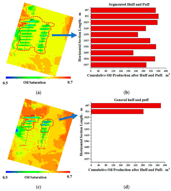
Figure 3.
Distribution of Remaining oil and production characteristics of perforation intervals under different huff-and-puff modes. (a) Oil saturation distribution under segmental huff-and-puff; (b) cumulative oil production per perforation interval under segmental huff-and-puff; (c) oil saturation distribution under overall huff-and-puff; (d) cumulative oil production per perforation interval under overall huff-and-puff.
Additionally, overall CO2 huff-and-puff can cause severe water production at the heel of the horizontal well, resulting in premature water breakthrough. This hinders effective mobilization of the remaining oil in the mid- and toe sections of the well, thereby reducing overall development efficiency.
The superior performance of the segmented huff-and-puff can be mainly attributed to the reservoir heterogeneity and the uneven sweep efficiency observed in the uniform mode. The segmented CO2 huff-and-puff mitigates the adverse effects of heterogeneity and improves the utilization of low-permeability zones, whereas the uniform CO2 huff-and-puff leads to significant production discrepancies among perforation intervals, resulting in poorer overall recovery efficiency. A comparison of the cumulative oil production profiles under different huff-and-puff modes further illustrates the production characteristics along the horizontal well. During uniform huff-and-puff, oil production is mainly concentrated near the heel section, with effective recovery limited to a horizontal length of 687–1025 m. When the horizontal well length exceeds 1025 m, the uniform mode can hardly mobilize additional oil, leading to low cumulative production.
In contrast, the segmented huff-and-puff enables more uniform reservoir stimulation across all well segments. Even for a 2000 m horizontal section, efficient oil displacement is achieved, significantly improving the recovery efficiency of tight shale oil reservoirs. Figure 3b,d present the cross-sectional comparison between uniform and segmented huff-and-puff, highlighting the distinct production behaviors of the two wells.
By comparing the production results after five years of operation under different huff-and-puff modes, the segmented CO2 huff-and-puff achieves a total incremental oil production over 69,608.74 m3 higher than that of the uniform huff-and-puff for the two wells (Figure 4a). Both wells (H1 and H2) exhibit notable increases in stage oil production. Meanwhile, the average water cut of the segmented huff-and-puff is 4.05% lower than that of the uniform mode (Figure 4b), indicating a water-cut reduction and enhanced oil recovery. These results demonstrate the significant advantages of the segmented CO2 huff-and-puff strategy over the conventional uniform mode.
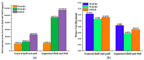
Figure 4.
Comparison of segmental and overall huff-and-puff modes. (a) Comparison of stage oil production; (b) comparison of water cut.
3.2. Influence of Segmental Huff-and-Puff Sequence
Two segmental huff-and-puff sequences were compared: (heel–middle–toe; toe–middle–heel). Figure 5a illustrates the three-stage CO2 injection process along the horizontal well. In one case, injection started from the heel to the toe, and in the other, from the toe to the heel, to evaluate the impact of different injection sequences. As illustrated in Figure 5b,c, the yellow zones in the profile represent the toe–middle–heel injection sequence, and the red zones represent the heel–middle–toe injection sequence. When the toe–middle–heel sequence was applied, the cumulative oil production at the toe perforation section of well H1 increased by an average of 53.64% compared to the heel–middle–toe sequence. For well H2, the increase was 23.21% at the toe perforation section. These results indicate that the injection sequence has a significant impact on CO2 huff-and-puff development in tight shale reservoirs. Injecting CO2 from the toe first and then toward the heel (i.e., toe–middle–heel sequence) yields significantly better performance.
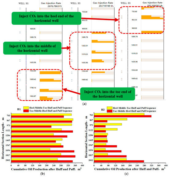
Figure 5.
Schematic of CO2 injection sequence in segmental huff-and-puff and its effect comparison. (a) Schematic diagram of CO2 injection process in segmental huff-and-puff (toe–middle–heel sequence); (b) oil production profile along the horizontal section of well H1; (c) oil production profile along the horizontal section of well H2.
During CO2 segmental huff-and-puff, injection begins at the toe of the horizontal well, targeting the remaining oil within the toe’s control area and displacing it toward the middle section of the well. Next, CO2 is injected into the middle section of the horizontal well to mobilize the remaining oil in that segment, while further displacing it toward the heel section. Finally, CO2 is injected into the heel section, mobilizing the remaining oil there. This sequence enables effective development of the horizontal well from the far end (toe) to the near end (heel), thereby enhancing the overall effectiveness of the segmental huff-and-puff process.
Figure 6a,b illustrate that altering the segmented huff-and-puff sequence in horizontal wells—by initiating CO2 injection from the toe—can significantly enhance oil recovery near the toe section. This approach enables more effective development of the distal portion of the horizontal well and alleviates the common issue of poor recovery in the far end of traditional tight shale wells. After simulating five years of production under different injection sequences (Figure 6c), the toe–middle–heel sequence achieved a stage cumulative oil production 845.17 m3 higher than that of the heel–middle–toe sequence, clearly demonstrating its superior recovery performance. The toe–middle–heel configuration drives residual oil from the distal end toward the heel, preventing inefficient backflow toward the toe and achieving the best overall huff-and-puff recovery. In contrast, the heel–middle–toe sequence tends to push residual oil farther into the distal region, increasing the difficulty of recovery.
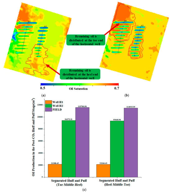
Figure 6.
Comparison of effects under different segmental huff-and-puff sequences (toe–middle–heel vs. heel–middle–toe). (a) Oil saturation distribution under segmental huff-and-puff (heel–middle–toe sequence); (b) oil saturation distribution under segmental huff-and-puff (toe–middle–heel sequence); (c) comparison of stage oil production under different injection sequences.
3.3. Impact of Injection Rate on Segmented Huff-and-Puff Performance
The superior performance of the high-rate segmented huff-and-puff over low-rate injection is primarily due to two factors: (1) a wider interaction zone between CO2 and crude oil, as illustrated in Figure 7a,b, where CO2 diffusion extends significantly farther under high-rate conditions. This allows CO2 to interact more fully with deeper parts of the horizontal section, promoting the flow of deep crude oil toward the wellbore and improving the overall effectiveness of CO2 huff-and-puff. (2) Greater sweep of residual oil: High-rate segmented CO2 injection mobilizes more residual oil than low-rate injection. The sweep volume of crude oil under high-rate injection is significantly larger, whereas low-rate injection leads to poor utilization of residual oil. These results further confirm that high-rate segmented huff-and-puff significantly enhances the development performance of CO2 injection in tight reservoirs.
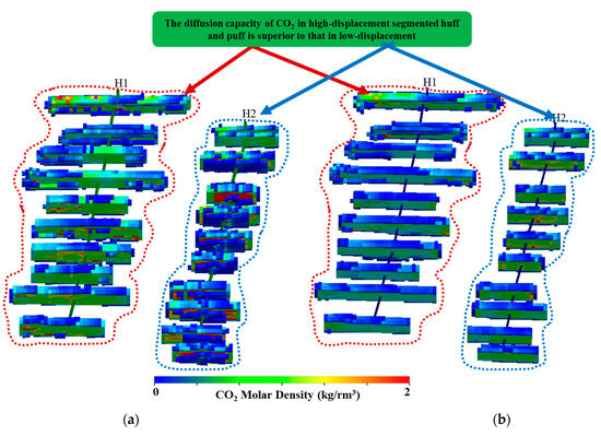
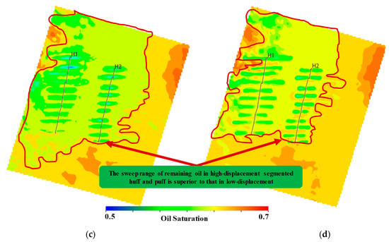
Figure 7.
Effects of CO2 segmental huff-and-puff under different injection rates. (a) CO2 diffusion under segmental huff-and-puff at high injection rate; (b) CO2 diffusion under segmental huff-and-puff at low injection rate; (c) oil saturation field under segmental huff-and-puff at high injection rate; (d) oil saturation field under segmental huff-and-puff at low injection rate.
By comparing huff-and-puff performance under different injection rates—while ensuring that the total CO2 injection volume remains consistent across all schemes—it was found that high-rate CO2 injection significantly outperforms low-rate injection in terms of effectiveness. Under high-rate injection, the cumulative oil production from both wells increased by 78,458.6 m3 compared to low-rate injection, indicating a remarkable oil enhancement effect (Figure 8a). Meanwhile, the water cut under high-rate injection was 4.87% lower than that under low-rate injection (Figure 8b). High-rate segmented CO2 huff-and-puff enhances oil recovery and controls water production compared to low-rate injection.
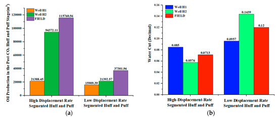
Figure 8.
Comparison of huff-and-puff performance between high and low injection rates. (a) Comparison of stage oil production; (b) comparison of water cut.
To compare the six CO2 huff-and-puff scenarios, three performance indicators were selected: water cut, recovery factor increment, and CO2 utilization efficiency. A depletion development case was used as the baseline for comparison. Among the six scenarios, the low-rate segmented CO2 huff-and-puff (heel–mid–toe) scheme demonstrated the best overall performance (Table 3). The high-rate generalized CO2 huff-and-puff case did not show data for the recovery factor increment or CO2 utilization because its cumulative oil production over the five-year period was lower than that of the depletion case.

Table 3.
Statistical results of different CO2 huff-and-puff schemes.
4. Conclusions
- (1)
- Compared with conventional huff-and-puff operations, segmented CO2 huff-and-puff in tight shale oil reservoirs can effectively mobilize the remaining oil in low-permeability zones and achieve efficient displacement even with a horizontal well length of 2000 m, thereby mitigating the adverse effects of reservoir heterogeneity.
- (2)
- The sequence of segmented huff-and-puff operations has a noticeable influence on horizontal well performance. Initiating CO2 injection from the toe section and proceeding successively toward the heel can drive the remaining oil from the distal end toward the near-well region, enhancing the utilization of residual oil in the far end. Compared with the heel–middle–toe sequence, this toe–middle–heel sequence reduces the water cut by 0.13% and increases the recovery factor by 0.07%, achieving the dual effect of water reduction and oil enhancement.
- (3)
- High-rate CO2 injection significantly expands the sweep volume and enhances CO2–oil interactions, thereby improving oil recovery from the deeper sections of the horizontal well. Under high-rate huff-and-puff conditions, the recovery factor increases by 7.13% compared with the low-rate injection, demonstrating enhanced flow capacity in low-permeability reservoir zones and improved mobilization of residual oil in tight streaks.
- (4)
- This study proposes, from a numerical simulation perspective, a feasible method for enhancing oil recovery through CO2 huff-and-puff in tight reservoirs. Experimental validation has not yet been conducted. Moreover, large-scale segmented CO2 huff-and-puff operations with different injection sequences impose higher technical requirements on field equipment; therefore, future research should focus on the development of supporting tools and technologies.
Author Contributions
Conceptualization, S.Q., X.L. and J.Y.; methodology, S.Y. and J.L.; formal analysis, M.W.; data curation, X.L.; writing—original draft preparation, S.Q.; writing—review and editing, Q.C.; project administration, J.Y. and J.L. All authors have read and agreed to the published version of the manuscript.
Funding
This research was funded by the CNPC Major Science and Technology Projects. (project number: 2023ZZ17YJ03).
Data Availability Statement
Data supporting the conclusions of this study: key data can be obtained from the corresponding author upon reasonable request. For instance, the data presented in Table 1 is derived from field numerical simulation data. Currently, the displacement rate data used in the field simulation is determined based on on-site implementation conditions; thus, these data are detailed and reliable.
Acknowledgments
The authors acknowledge the technical support provided by Changqing Oilfield Research Institute.
Conflicts of Interest
Authors Songchao Qi, Jiuzheng Yu, Jianshan Li, Xiaochun Liu and Shichun Yu were employed by Changqing Oilfield Branch Company, PetroChina. The remaining authors declare that the research was conducted in the absence of any commercial or financial relationships that could be construed as a potential conflict of interest. The authors declare that this study received funding from China National Petroleum Corporation (CNPC) and Changqing Oilfield Branch Company. The funder was not involved in the study design, collection, analysis, interpretation of data, the writing of this article or the decision to submit it for publication.
References
- Chen, Z.; Li, R.; Yang, S.; Qin, Y.; Gong, L.; Zhang, D. A novel algorithm for asphaltene precipitation modeling in shale reservoirs with the consideration of capillary pressure during the CCUS processes. Appl. Therm. Eng. 2024, 248 Pt A, 123217. [Google Scholar] [CrossRef]
- Guo, Y.N.; Feng, R.; Lei, Q.; Chen, Y. Advances and prospects in efficient development technologies for tight sandstone reservoirs. Petrochem. Ind. Technol. 2025, 32, 231–233. [Google Scholar]
- Hu, Y.L.; Hao, M.Q.; Chen, G.L.; Sun, R.; Li, S. Technologies and practice of CO2 flooding and sequestration in China. Pet. Explor. Dev. 2019, 46, 716–727. [Google Scholar] [CrossRef]
- Ma, J.H.; Wang, X.Z.; Gao, R.M.; Zeng, F.H.; Huang, C.X.; Tontiwachwuthikul, P.P.; Liang, Z.W. Enhanced light oil recovery from tight formations through CO2 huff-n-puff processes. Fuel 2015, 154, 35–44. [Google Scholar] [CrossRef]
- Zhang, D.P. CO2 flooding enhanced oil recovery technique and its application status. Sci. Technol. Rev. 2011, 29, 75–79. [Google Scholar]
- Zhang, Y.H.; Sheng, J.P.; Li, Q.X.; Song, P.; Chen, Y.K.; Tan, J.H. Advances in the application of CO2 stimulation technology. Spec. Oil Gas Reserv. 2021, 28, 1–10. [Google Scholar]
- Zhou, T.; Liu, X.W.; Wang, Y.L.; Qin, C.G.; Gai, C.C. Experiment of CO2 huff-n puff process in staged fracturing horizontal wells for developing tight oil reservoirs. J. Southwest Pet. Univ. Sci. Technol. Ed. 2017, 39, 125–131. [Google Scholar]
- Halinda, D.; Zariat, A.A.; Muraza, O.; Marteighianti, M.; Setyawan, W.; Haribowo, A.; Rajab, M.; Firmansyah, M.; Hasan, I.; Nurlia, D.; et al. CO2 huff and puff injection operation overview in Jatibarang field lessons learned from a successful case study in mature oil field. In Proceedings of the ADIPEC, Abu Dhabi, United Arab Emirates, 2–5 October 2023. [Google Scholar] [CrossRef]
- Huang, X.; Li, X.; Zhang, Y.; Li, T.; Zhang, R. Microscopic production characteristics of crude oil in nano-pores of shale oil reservoirs during CO2 huff and puff. Pet. Explor. Dev. 2022, 49, 557–564. [Google Scholar] [CrossRef]
- Lang, D.; Lun, Z.; Lyu, C.; Wang, H.; Zhao, Q.; Sheng, H. Nuclear magnetic resonance experimental study of CO2 injection to enhance shale oil recovery. Pet. Explor. Dev. 2021, 48, 603–612. [Google Scholar] [CrossRef]
- Zhang, Y.; Yuan, L.; Liu, S.; Zhang, J.; Yang, M.; Song, Y. Molecular dynamics simulation of bubble nucleation and growth during CO2 huff-and-puff process in a CO2-heavy oil system. Geoenergy Sci. Eng. 2023, 227, 211852. [Google Scholar] [CrossRef]
- Jiang, J.S.; Liu, Q.J.; Wang, J.L. Calculation method for effective radius of carbon dioxide huff and puff in tight reservoirs. Sci. Technol. Eng. 2020, 20, 2216–2222. [Google Scholar]
- Ma, Q.Z.; Yang, S.L.; Chen, H.; Wang, L.; Qian, K.; Meng, Z.; Lei, H.; Wang, Z.L. Effect and influencing factors of CO2 huff and puff in a tight oil reservoir—Taking the Lucaogou formation in the Xinjiang Jimsar sag as an example. Pet. Sci. Bull. 2018, 04, 434–445. [Google Scholar]
- Tang, X.; Li, Y.; Han, X.; Zhou, Y.; Zhan, J.; Xu, M.; Zhou, R.; Cui, K.; Chen, X.; Wang, L. Dynamic characteristics and influencing factors of CO2 huff and puff in tight oil reservoirs. Pet. Explor. Dev. 2021, 48, 817–824. [Google Scholar] [CrossRef]
- Abedini, A.; Torabi, F. On the CO2 storage potential of cyclic CO2 injection process for enhanced oil recovery. Fuel 2014, 124, 14–27. [Google Scholar] [CrossRef]
- Hou, G. Practice and understanding of the CO2 huff-puff for the volume fractured horizontal well in tight oil reservoirs. Pet. Geol. Oilfield Dev. Daqing 2018, 37, 163–167. [Google Scholar]
- Liu, G. Optimization of injection and production parameters of CO2 huff and puff by horizontal wells with volume fracturing in tight oil. Pet. Geol. Eng. 2020, 34, 90–93. [Google Scholar]
- Liu, J.; Li, H.; Tan, Q.; Liu, S.; Zhao, H.; Wang, Z. Quantitative study of CO2 huff-and-puff enhanced oil recovery in tight formation using online NMR technology. J. Pet. Sci. Eng. 2022, 216, 110688. [Google Scholar] [CrossRef]
- Abedini, A.; Torabi, F. Oil recovery performance of immiscible and miscible CO2 huff-and-puff processes. Energy Fuels 2014, 28, 774–784. [Google Scholar] [CrossRef]
- Li, L.; Su, Y.; Sheng, J.J.; Hao, Y.; Wang, W.; Lv, Y.; Zhao, Q.; Wang, H. Experimental and numerical study on CO2 sweep volume during CO2 huff-and-puff EOR process in shale oil reservoirs. Energy Fuels 2019, 33, 4017–4032. [Google Scholar] [CrossRef]
- Perera, M.; Gamage, R.; Rathnaweera, T.; Ranathunga, A.; Koay, A.; Choi, X. A review of CO2-enhanced oil recovery with a simulated sensitivity analysis. Energies 2016, 9, 481. [Google Scholar] [CrossRef]
- Talebian, S.H.; Masoudi, R.; Tan, I.M.; Zitha, P.L.J. Foam assisted CO2-EOR: A review of concept, challenges, and future prospects. J. Pet. Sci. Eng. 2014, 120, 202–215. [Google Scholar] [CrossRef]
- Rezaei, F.; Rezaei, A.; Jafari, S.; Hemmati-Sarapardeh, A.; Mohammadi, A.H.; Zendehboudi, S. On the evaluation of interfacial tension (IFT) of CO2-paraffin system for enhanced oil recovery process: Comparison of empirical correlations, soft computing approaches, and parachor model. Energies 2021, 14, 3045. [Google Scholar] [CrossRef]
- Hao, H.; Hou, J.; Qu, M.; Guo, W.; Deng, S.; Liu, H. Using a well-to-well interplay during the CO2 huff-and-puff process for enhanced oil recovery in an inclined oil reservoir: Experiments, simulations, and pilot tests. Front. Energy Res. 2023, 10, 1002053. [Google Scholar] [CrossRef]
- Chen, C.; Balhoff, M.; Mohanty, K.K. Effect of reservoir heterogeneity on primary recovery and CO2 huff-and-puff recovery in shale-oil reservoirs. SPE Reserv. Eval. Eng. 2014, 17, 404–413. [Google Scholar] [CrossRef]
- Orozco, D.; Fragoso, A.; Selvan, K.; Noble, G.; Aguilera, R. Eagle Ford huff-and-puff gas-injection pilot: Comparison of reservoir simulation, material balance, and real performance of the pilot well. SPE Reserv. Eval. Eng. 2020, 23, 247–260. [Google Scholar] [CrossRef]
- Gamadi, T.D.; Elldakli, F.; Sheng, J.J. Compositional simulation evaluation of EOR potential in shale oil reservoirs by cyclic natural gas injection. In Proceedings of the SPE/AAPG/SEG Unconventional Resources Technology Conference, Denver, CO, USA, 25–27 August 2014. [Google Scholar]
- Elturki, M.; Imqam, A. Experimental investigation of asphaltene deposition and its impact on oil recovery in Eagle Ford Shale during miscible and immiscible CO2 huff-n-puff gas injection. Energy Fuels 2023, 37, 2993–3010. [Google Scholar] [CrossRef]
- Chen, H.; Hu, Y.; Kang, Y.; Wang, X.C.; Liu, F.; Liu, Y.W. Advantages of supercritical CO2 compound fracturing in shale on fracture geometry, complexity and width. J. Nat. Gas Sci. Eng. 2021, 93, 104033. [Google Scholar] [CrossRef]
- Moosavi, N.; Bagheri, M.; Nabi-Bidhendi, M. Hydrocarbon reservoir parameter estimation using a fuzzy Gaussian-based SVR method. Bull. Geophys. Oceanogr. 2024, 65, 70. [Google Scholar] [CrossRef]
- Mehrabi, A.; Bagheri, M.; Nabi-Bidhendi, M.; Biniaz Delijani, E.; Behnoud, M. Improved porosity estimation in complex carbonate reservoirs using a hybrid CRNN deep-learning model. Earth Sci. Inform. 2024, 17, 4773–4790. [Google Scholar] [CrossRef]
Disclaimer/Publisher’s Note: The statements, opinions and data contained in all publications are solely those of the individual author(s) and contributor(s) and not of MDPI and/or the editor(s). MDPI and/or the editor(s) disclaim responsibility for any injury to people or property resulting from any ideas, methods, instructions or products referred to in the content. |
© 2025 by the authors. Licensee MDPI, Basel, Switzerland. This article is an open access article distributed under the terms and conditions of the Creative Commons Attribution (CC BY) license (https://creativecommons.org/licenses/by/4.0/).