Article

Physical-Guided Dynamic Modeling of Ultra-Supercritical Boiler–Turbine Coordinated Control System Under Wet-Mode Operation

by
Ge Yin
1,
He Fan
2,*,
Xianyong Peng
2,*,
Yongzhen Wang
2,
Yuhan Wang
2,
Zhiqian He
2,
Ke Zhuang
1,
Guoqing Chen
1,
Zhenming Zhang
1,
Xueli Sun
1,
Wen Sheng
2,
Min Xu
3,
Hengrui Zhang
4,
Yuxuan Lu
5 and
Huaichun Zhou
2
1
State Key Laboratory of Low-Carbon Smart Coal-Fired Power Generation and Ultra-Clean Emission, China Energy Science and Technology Research Institute Co., Ltd., Nanjing 210023, China
2
Jiangsu Provincial Engineering Research Center for Smart Energy Technology and Equipment, School of Low-Carbon Energy and Power Engineering, China University of Mining and Technology, No.1, Daxue Road, Xuzhou 221116, China
3
China Coal Yudian (Yuhuan) Energy Development Co., Ltd., Taizhou 317604, China
4
Department of Aviation Material Support and Si Zhan Support, Air Force Logistics College, No. 85, Xige Street, Xuzhou 221005, China
5
School of Energy and Environment, Southeast University, Nanjing 210096, China
*
Authors to whom correspondence should be addressed.
Processes 2025, 13(11), 3625; https://doi.org/10.3390/pr13113625 (registering DOI)
Submission received: 15 August 2025 / Revised: 31 August 2025 / Accepted: 5 September 2025 / Published: 9 November 2025
(This article belongs to the Section Energy Systems)

Abstract

To accommodate the high penetration of intermittent renewable energy sources like wind and solar power into the grid, coal-fired units are required to operate with enhanced deep peak-shaving and variable load capabilities. This study develops a dynamic model of the boiler–turbine coordinated control system (BTCCS) for ultra-supercritical once-through boiler (OTB) coal-fired units operating under wet conditions. A mechanistic model framework is established based on mass and energy conservation. In case of missing steady-state data, this work proposes a mechanism-integrated parameter identification method that determines model parameters using only dynamic running data while incorporating physical constraints. Model validation demonstrates that the proposed approach accurately reproduces the variable-load operation of the BTCCS within the range of 50–350 MW. Mean relative errors of output variables are all less than 7.5%, and root mean square errors of output variables are less than 0.3 MPa, 1.4 kg/s, 0.25 m, and 20.7 MW, respectively. Open-loop simulations further confirm that the model captures the essential dynamic characteristics of the system, making it suitable for simulation studies and control system design aimed at improving operational flexibility and safety of OTB coal-fired units under wet conditions.

1. Introduction

To facilitate the grid’s integration of stochastic and intermittent renewable energy generation [1], once-through boiler coal-fired units (OTB) must enhance their deep peak-shaving capabilities and operational safety, thereby contributing to a new power system primarily driven by renewable energy [2]. However, operating OTB coal-fired units under variable loads in wet conditions diminishes the safety of boiler water circulation and operational stability of the water wall. Additionally, the limited capacity of the unit’s storage tank leads to significant water level fluctuations during variable-load operations, potentially causing water to enter the superheater inlet steam and jeopardize the superheater’s operational safety. Consequently, it is essential to develop a dynamic model of the boiler–turbine coordinated control system (BTCCS) for OTB coal-fired units under wet conditions. This model should accurately represent the system’s dynamic operational characteristics in such conditions and be utilized in designing control systems [3] to improve the operational flexibility and safety of OTB coal-fired units under wet conditions.
Currently, research on the BTCCS for OTB coal-fired units predominantly focuses on dry-mode operation, with fewer studies addressing dynamic modeling under wet conditions. Gao et al. [4] developed a dynamic model for the BTCCS of OTB coal-fired units that facilitates transitions between dry and wet modes. However, their study did not demonstrate the dynamic characteristics necessary to validate the model’s structural accuracy. Wang et al. [5] employed a hybrid modeling method to establish a simplified control model for the BTCCS of OTB coal-fired units under wet conditions, but this model lacks a physical description of the water storage tank level, complicating control system design. Liu et al. [6] integrated the core steam–water system model of once-through boilers with the traditional drum boiler load system model to derive a nonlinear dynamic model applicable to both dry and wet conditions. Nonetheless, the absence of a mechanistic modeling process necessitates validation of the model’s dynamic accuracy and structural integrity. Thus, further research is essential to advance the dynamic modeling of the BTCCS for OTB coal-fired units under wet conditions, aiming to improve operational flexibility and safety.
Building on the dynamic modeling studies of the BTCCS of OTB coal-fired units under dry conditions, it is advantageous to extend this research to wet conditions. Currently, the primary dynamic modeling methods for the BTCCS in OTB units include industrial software modeling, the hybrid modeling method, and data-driven approaches. For the industrial software modeling method, Hentschel J et al. [7] focused on the detailed modeling of a hard coal-fired power plant using the thermohydraulic simulation software APROS 6.12. Sarda P et al. [8] developed a plant-wide dynamic model of a supercritical pulverized coal power plant using Aspen Plus Dynamic V12. However, time-consuming simulation and a complex modeling procedure are the main shortcomings that limit its further development. The hybrid modeling method constructs a system’s physical framework by applying fundamental conservation laws and analyzing operational mechanisms, while also identifying functional relationships and parameters through operational data. The advantages of this method lie in its reliable physical model structure, which effectively characterizes system dynamics while maintaining appropriate model accuracy. However, there exist some essential assumptions to simplify the model structure, and running data are utilized partially to identify parameters and functions in a model based on nonlinear or linear regressions. Therefore, the hybrid modeling method can capture the essential dynamic characteristics of the system with proper accuracy. Liu et al. [9,10,11,12] employed the lumped parameter method to mechanistically analyze the variable load operation of the BTCCS, establishing a nonlinear dynamic model for an ultra-supercritical (USC) coal-fired unit that accurately reflects system dynamics under dry conditions. To describe low-load operations, Niu et al. [13] developed a dynamic model for the BTCCS of a 600 MW supercritical unit using the lumped parameter method, effectively capturing the variable load operation process at 30–50% of the rated load under dry conditions. Tian et al. [14] established the energy balance process for thermal energy storage in both metal heat transfer zones and the steam–water volumetric regions, established a core steam–water system model of once-through boilers and analyzed the coupling characteristics between steam pressure and intermediate point temperature. Zhou et al. [15] developed an affine nonlinear model for the intermediate point temperature (IPT) in a 600 MW supercritical once-through boiler by establishing simplified mechanism equations for the evaporation zone and steam separator. Go et al. [16] developed a compact lumped-parameter model for supercritical once-through boiler water–wall systems using pressure- and temperature-based dynamic equations, validated against the APESS industrial simulator. Xie et al. [17] established a unified dynamic model for supercritical once-through boiler–turbine units across all load conditions by analyzing recirculation characteristics, using modified steam dryness as a transition indicator, and optimizing parameters via an improved dynamic search fireworks algorithm, achieving high accuracy for full-range automated control. Tian et al. [18] further used a hybrid modeling method and model order reduction (MOR) technique to develop a BTCCS of a 1000 MW USC unit. Esmaeili et al. [3] considered an accurate gray box multivariable coupled nonlinear model for ultra-supercritical boiler–turbine units to regulate steam pressure, separator enthalpy, and power output through fuel, feedwater, and throttle valve manipulations. Xie et al. [19] established a hybrid model integrating the INFO algorithm and XGBoost for supercritical once-through coal-fired units, which accurately captures dynamic characteristics across all operational modes. Deng et al. [20] developed a dynamic model for a 600 MW supercritical boiler start-up process using a six-equation two-phase flow solution for the evaporator, validated for operations from ignition to 30% BMCR load, demonstrating clear dynamic behavior. Based on mass and energy balance and thermodynamic principles, Zhang et al. [21] established a validated dynamic model for a 350 MW supercritical circulating fluidized bed unit using parameter identification with a quantum genetic algorithm, demonstrating accurate capture of special dynamic characteristics under variable loads. Additionally, Fan et al. [22] established a dynamic model for a BTCCS in a USC unit operating at 50–100% of rated load, which served as a basis for a dynamic model covering 35–100% of rated load [23] and a dynamic model incorporating superheated steam temperature [24]. Haddad et al. [25] investigated the procedure of parameter identification and refinement of 600 MW supercritical power plant. The model is derived from physical and mathematical principles, and different optimization algorithms are used to compare and identify parameters and functions in the model. But the procedure of parameter identification lacks mechanism analysis, which may deteriorate dynamic modeling performance. Taler et al. [26] developed a distributed parameter model of a supercritical power plant to achieve the boiler dynamics, but wide-load dynamic running data are required to further validate the performance of simulating rapid changes in boiler thermal loading.
In hybrid modeling, obtaining model parameters and functions requires combining multiple sets of steady-state operation data with regression analysis. However, acquiring multiple sets of steady-state data during variable loads is challenging, limiting the method’s applicability.
Unlike the hybrid modeling method, the data-driven modeling approach utilizes the dynamic operation data and intelligent modeling techniques, such as neural networks and fuzzy systems, to construct system models. These models exhibit high dynamic accuracy, but their structural reliability is often compromised due to the absence of mechanism analysis. Ghaffari et al. [27] developed a soft computing model integrating fuzzy logic, neural networks, and genetic algorithms for characterizing power plant subsystem dynamics, demonstrating higher accuracy than traditional thermodynamic models through field data validation. Liu et al. [28] developed a data-driven model for a 1000 MW BTCCS using a fuzzy neural network integrated with dynamic operational data of the unit, achieving superior modeling accuracy compared to the recursive least squares algorithm. Additionally, various neural network architectures, including long- and short-term memory neural networks [29], deformation neural networks [30], and input convex neural networks [31], have been employed to model the BTCCS. In the realm of fuzzy systems, Hou et al. [32,33,34] utilized a fuzzy model to construct the BTCCS of OTB coal-fired units. Lee et al. [35] developed a dynamic recurrent neural network (DRNN) model for a once-through boiler plant to enable intelligent control, addressing computational limitations of optimal control by successfully implementing a reference governor with intelligently tuned PID feedback. Dai et al. [36] proposed a process knowledge-guided multi-agent deep reinforcement learning framework for distributed optimization control of once-through boiler–turbine units, significantly improving load response speed and control performance compared to traditional methods. Huang et al. [37] applied an adaptive optimization algorithm, in conjunction with operational data, to identify the transfer function model of the BTCCS under an 800 MW load condition. Validation results indicate that this model possesses adequate accuracy and is suitable for control system design.
To describe the dynamic characteristics of the BTCCS in an OTB coal-fired unit under wet conditions, this paper employs a hybrid modeling approach to develop a system dynamic model, and introduces a parameter identification method that utilizes only dynamic operational data while integrating mechanistic characteristics to ascertain the system model parameters and establish a system dynamic model. Furthermore, open-loop simulation analysis and dynamic accuracy validation of the model are conducted to demonstrate the validity of the constructed model.

2. Description of BTCCS for OTB Coal-Fired Units Under Wet Conditions

2.1. Operational Process of BTCCS for OTB Coal-Fired Units Under Wet Conditions

The research focus of this paper is a 1000 MW OTB coal-fired unit located at China Resources (Xuzhou) Electric Power Co., Ltd., Xuzhou, China, whose parameters detailed in Table 1. Figure 1 illustrates the unit operating under wet conditions. As the unit load gradually decreases, both the flow rate of the working fluid entering the water wall and the amount of coal fed into the furnace diminish. To maintain the boiler’s hydrodynamic stability, the feedwater flow rate is reduced to a certain level, generally 30% of the boiler’s maximum continuous evaporation, and then held steady. With the reduction in boiler thermal load, the heat absorption by the working fluid decreases, causing the water-wall outlet fluid to transition from slightly superheated steam to wet steam. To prevent water from entering the superheater, the steam–water separator performs separation, directing saturated steam to the superheater and saturated water to the water storage tank. To recover heat from the working fluid and saturated water, the boiler water circulating pump mixes higher temperature water with hot water from the high-pressure heater before it enters the economizer. This describes the operational process of coal-fired units under wet conditions. The wet operation process of the unit is complex due to the limited capacity of the water storage tank, making the water level difficult to control. This can easily lead to water ingress into the superheater or direct discharge of hot water from the water storage tank, compromising the safety and efficiency of unit operation.

2.2. Control Model Variables of BTCCS for OTB Coal-Fired Units Under Wet Conditions

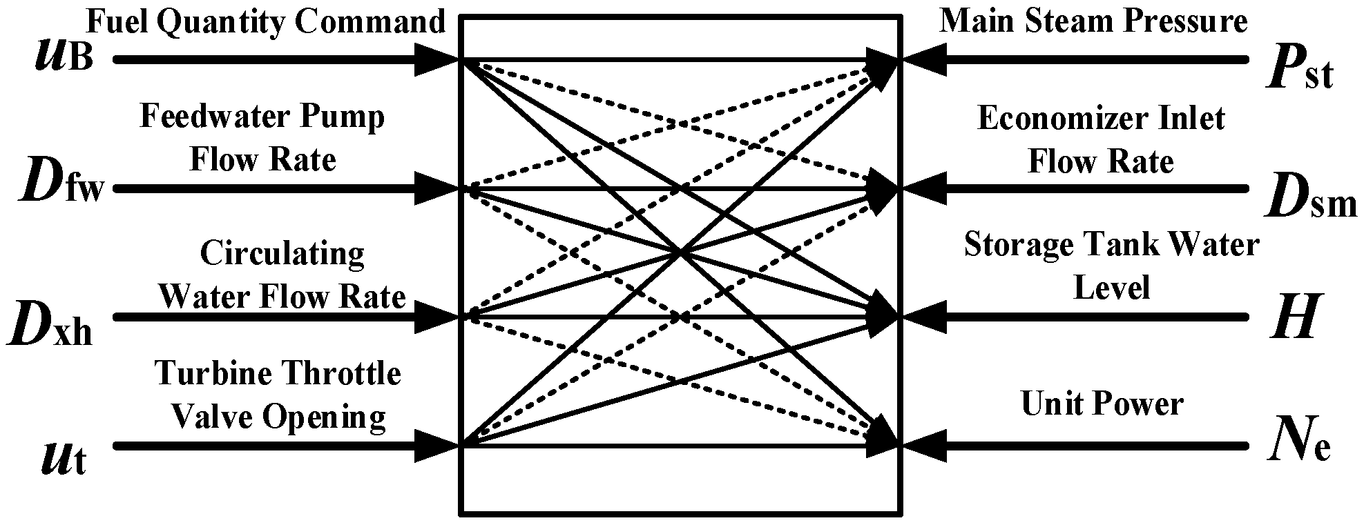
For the CCS model of OTB coal-fired units under wet conditions, feedwater flow at the inlet of the economizer should be kept at the minimum safe limit of feedwater flow to maintain the boiler’s hydrodynamic stability. In addition, circulating water flow rate and feedwater pump flow rate are adjusted coordinately to maintain a stable storage tank water level and then prevent wet steam from entering the superheater to ensure the operational safety and efficiency of the unit. Combined with the CCS model under dry conditions, the BTCCS model for an OTB coal-fired unit operating under wet conditions incorporates four inputs: fuel demand command uB (kg/s), feedwater pump flow rate Dfw (kg/s), turbine throttle opening ut, and circulating water flow rate Dxh (kg/s). It also includes four outputs: economizer inlet flow rate Dsm (kg/s), unit load Ne (MW), main steam pressure Pst (MPa), and storage tank water level l (m). Figure 2 illustrates the correspondence between these input and output variables:

3. Dynamic Modeling of BTCCS for OTB Coal-Fired Units Under Wet Conditions

Before system modeling, several simplifying assumptions are necessary for the model.
(A1) The economizer and water wall are treated as a single-pipe heating system;
(A2) The superheater is also considered a single-pipe heating system, provided that superheated steam temperature can be stably controlled and the desuperheating water flow rate is integrated into the superheater inlet flow rate;
(A3) Axial heat transfer between the flue gas, boiler tube wall, and the working fluid is neglected;
(A4) The heat transferred from the flue gas to the boiler tube walls is assumed to be approximately proportional to the heat released from coal combustion;
(A5) For any heated tube, the fluid properties are assumed to be uniformly distributed across its cross-sectional area;
(A6) The high-, medium-, and low-pressure cylinders of a turbine are considered collectively as a turbine system;
(A7) The heat absorbed by the reheater is attributed to the steam turbine coefficient.

3.1. Dynamic Modeling of Pulverizing System

The dynamic operational process of the pulverizing system can be modeled as a first-order inertia system with a time delay [13], so the dynamic model of the pulverizing system is
d r B d t = 1 c 0 r B + 1 c 0 u B ( t τ ) ,
where c0 is the inertia time of the pulverizing system, s; rB is the coal feed rate, kg/s; uB is the fuel quantity command, kg/s; τ denotes the time delay in the pulverizing system, s; and t denotes the current time, s.

3.2. Dynamic Modeling of the Economizer and Water-Wall System

Since the flow rates of the feedwater pump (Dfw) and boiler water circulating pump (Dxh) converge at the economizer, the inlet working fluid flow of the economizer (Dsm) can be expressed as follows:
d D sm d t = 1 T xh ( D sm + D fw + D xh ) ,
where Txh is the inertia time, s; Dsm is feed flow at inlet of economizer, kg/s; Dfw is the feedwater pump flow rate, kg/s; and Dxh is the circulating pump flow rate, kg/s.
The operational process of the economizer and water wall is analyzed through a mechanism-based approach. Utilizing the principles of working fluid mass and energy conservation, a lumped parameter modeling technique is applied. In this approach, the system outlet is designated as the lumped parameter point, establishing a dynamic model for the economizer and water-wall system, namely,
d ( ρ lb V lb ) d t = D sm D lb , d ( ρ lb V lb h lb + c j m j T j ) d t = D sm h sm D lb h lb + Q 1 , Q = k 1 r B ,
where ρlb is the water-wall output working fluid density, kg/m3; Vlb is the economizer and water-wall volume, m3; Dlb is the flow rate at outlet of water wall, kg/s; hlb is the working fluid enthalpy at outlet of water wall, kJ/kg; cj is the boiler metal wall specific heat capacity, kJ/(kg·°C); mj is the boiler tube wall metal mass, kg; Tj is the boiler tube wall metal temperature, °C; hsm is the economizer inlet working fluid enthalpy, kJ/kg; Q1 is the heat absorbed by the working fluid in the economizer and water wall, kJ/s; and k1 is the heat absorbed by working fluid in the economizer and water wall when 1 kg of coal is burned, kJ/(kg·s).
According to assumptions (A1) and (A3)–(A5), Equation (3) is derived for the water-wall outlet steam pressure and enthalpy, respectively, and are given by
V lb ρ lb p lb d p lb d t + ρ lb h lb d h lb d t = D sm D lb , ( V lb h lb ρ lb p lb + c j m j T j p lb ) d p lb d t + ( V lb h lb ρ lb h lb + ρ lb V lb + c j m j T j h lb ) d h lb d t = D sm h sm D lb h lb + Q 1 ,
where plb is the water-wall outlet working fluid pressure (MPa); due to the uniform force exerted by working fluid at the outlet of the steam separator, it is reasonable to assume that the pressure of working fluid at the water-wall outlet is equal to the pressure at the steam separator, namely, plb = pm.
Equation (4) can be further written as
c 1 d p m d t = ( h sm d 1 ) D sm + ( d 1 h lb ) D lb + Q 1 , c 2 d h lb d t = ( h sm d 2 ) D sm + ( d 2 h lb ) D lb + Q 1 ,
where b 11 = V l b ρ l b / p m , b 12 = V l b ρ l b / h l b , b 21 = h l b V l b ρ l b / p m + c j m j T j / p m , b 22 = h l b V l b ρ l b / h l b + ρ l b V l b + c j m j T j / h l b , c 1 = b 21 b 11 b 22 / b 12 , d 1 = b 22 / b 12 , c 2 = b 22 b 12 b 21 / b 11 , d 2 = b 21 / b 11 .

3.3. Dynamic Modeling of Water Storage Tank System

According to Equation (5), the dryness model of the working fluid at the water-wall outlet can be expressed as xlb = x (pm, hlb). Consequently, applying the law of conservation of mass, the dynamic model of the water storage tank system is formulated as follows:
d ( V H ρ H ) d t = ( 1 x lb ) D lb D xh ,
Since the storage tank is in a saturated state, the mass of the working fluid in the storage tank can be expressed as V H ρ H = V s ρ s + V w ρ w , where V s is the saturated steam volume, m3; ρ s is the saturated steam density, kg/m3; V w is the saturated water volume, m3; ρ w is the saturated water density, kg/m3; V H is the volume in storage tank, m3; and ρ H is the density of working fluid in storage tank, kg/m3. Due to the small mass of saturated steam, the mass of the working fluid in the storage tank can be approximated as V H ρ H V w ρ w , V w = F H , where F is the bottom area of storage tank, m2; and H is the height of the storage tank, m. Additionally, the saturated water density can be expressed in terms of the working pressure, namely, ρ w = ρ p m . Consequently, the dynamic model of the water level in the storage tank can be obtained as follows:
d H d t = ( 1 x lb ) D lb D xh ρ w F .

3.4. Dynamic Modeling of Superheater System

Based on assumption (A2), a mechanism analysis of the economizer and water-wall system operational process is conducted. Utilizing the principles of working fluid mass and energy conservation, a lumped parameter modeling approach is applied, with the system outlet serving as the lumped parameter point, to establish a dynamic model for superheated steam enthalpy in superheater system, namely,
d ( ρ st V st h st ) d t = ( ρ st h st V st h st + ρ st V st ) d h s t d t = x lb D lb ( h vbh h st ) + Q 2 , Q 2 = k 2 x 1 ,
where ρ s t is the superheater outlet working fluid density, kg/m3; V s t is the superheater volume, m3; D l b is the water-wall outlet flow rate, kg/s; h v b h is the superheater inlet saturated steam enthalpy, kJ/kg; h s t is the superheater outlet steam enthalpy, kJ/kg; Q 2 is the heat absorbed by the working fluid in the superheater, kJ/s; and k 2 is the heat absorbed by the working fluid in the superheater when 1 kg of coal is burned, kJ/(kg·s). Let c 31 = h s t V s t ρ s t / h s t and c 32 = ρ s t V s t .
Referring to the energy balance equation for the steam storage process within the volume zone, and integrating it with Equation (8), a dynamic model for the superheated steam pressure in the superheater system is established, namely,
d ( ρ st V st h st ) d t = ρ st p st V st h st d p st d t = x lb D lb ( h st h vbh ) k 3 p st u t ,
where p s t is the superheater outlet working fluid pressure, MPa; k 3 is the steam turbine fitting coefficient, kJ/(MPa·s); and u t is the steam turbine valve opening We then let c 4 = h s t V s t ρ s t / p s t .

3.5. Dynamic Modeling of Steam Turbine System

According to assumptions (A6) and (A7), the steam turbine system can be described by a first-order inertial system [24], namely,
d N e d t = 1 c 5 ( N e + k 4 k 3 p st u t ) ,
where N e is the unit power, MW; c 5 is the steam turbine inertia time, s; and k 4 is the steam turbine efficiency coefficient.

3.6. Dynamic Model Structure of BTCCS for OTB Coal-Fired Units Under Wet Conditions

The state space model takes the specific form:
x ˙ 1 = 1 c 0 x 1 + 1 c 0 u 1 ( t τ ) , x ˙ 2 = 1 T xh ( x 2 + u 2 + u 3 ) , x ˙ 3 = 1 c 1 [ ( h sm d 1 ) D sm + ( d 1 x 4 ) D lb + Q 1 ] , x ˙ 4 = 1 c 2 [ ( h sm d 2 ) D sm + ( d 2 x 4 ) D lb + Q 1 ] , x ˙ 5 = 1 c 31 x 5 + c 32 [ x lb D lb ( h vbh x 5 ) + Q 2 ] , x ˙ 6 = 1 c 4 x 5 [ x lb D lb ( x 5 h vbh ) k 3 x 6 u t ] , x ˙ 7 = 1 c 5 [ x 7 + k 4 k 3 x 6 u t ] , x ˙ 8 = 1 ρ w F [ x lb D lb D xh ] ,
where
x lb = x ( p m , h lb ) , D lb = f ( p m , h lb ) , Q 1 = k 1 x 1 , Q 2 = k 2 x 1 , h vbh = h ( x 3 ) , ρ w = ρ ( x 3 ) ,
[ u 1 , u 2 , u 3 , u 4 ] = [ u B , D fw , D xh , u t ] , [ y 1 , y 2 , y 3 , y 4 ] = [ p st , D sm , H , N e ] , [ x 1 , x 2 , x 3 , x 4 , x 5 , x 6 , x 7 , x 8 ] = [ r B , D sm , p m , h lb , h st , p st , N e , H ] .

4. Parameter Identification

The dynamic model of the BTCCS, represented by Equation (11), requires the identification of seven static parameters: k 1 , k 2 , k 3 , k 4 , h v b h , ρ w , and h s m ; two nonlinear functions, x l b and D l b ; and eleven dynamic parameters: τ , c 0 , T x , c 1 , d 1 , c 2 , d 2 , c 31 , c 32 , c 4 , and c 5 . When operating under variable load conditions in the wet state, the unit exhibits fewer steady-state load segments. Consequently, this study introduces a parameter identification method that leverages mechanistic characteristics, utilizing solely variable load dynamic data to identify the system’s static and dynamic parameters and nonlinear functions. The method proceeds as follows:
Step 1 involves selecting a set of variable load operational data and uniformly choosing unit load interval points to preliminarily understand the system parameter change rule. This step determines the system variable values corresponding to each unit load point and constructs a system variable data set with uniform intervals of unit load.
Step 2 focuses on the working fluid heat absorption functions Q 1 and Q 2 , ensuring that heat absorption increases proportionally with the coal feed rate. This requires defining the parametric structures   k 1 = k x 1 and k 2 = g x 1 as quadratic function sets. By differentiating these functions, where Q i = k i x 1 and i = 1 ,   2 , the heat absorption rate of the working fluid must consistently be greater than zero across the load variation range to satisfy system mechanistic characteristics. If this condition is unmet, data selection and parameter identification for k 1 and k 2 must be revisited.
Step 3 uses regression analysis methods to identify static parameters k 3 , k 4 , h v b h , and ρ w based on the system variable data set.
Step 4 considers the economizer inlet working fluid flow rate approximately equal to the water-wall outlet working fluid flow rate during variable load operation, namely, D s m D l b . According to mechanistic properties and the literature, the function structure is determined as D l b = u t a 1 p m + b 1 / a 2 h l b + b 2 . Since the working fluid at the water-wall outlet is in the wet steam state, the wet steam dryness model is x l b = a 11 h l b + b 11 / a 22 p m + b 22 , using the mechanistic properties of wet steam and water steam thermal property software.
Step 5 involves systematically identifying dynamic parameters using operational data combined with an optimization algorithm. This process begins with identifying the dynamic parameter T x , followed by identifying additional dynamic parameters, τ , c 0 , c 1 , d 1 , c 2 , and d 2 ; then c 31 and c 32 ; and finally, c 4 and c 5 , in sequence.
The flowchart illustrating this mechanism-integrated parameter identification method is presented in Figure 3.
In accordance with the mechanism-integrated parameter identification method, a segment of dynamic operation data set is selected, and the values of system variables corresponding to each unit load point are provided in Table 2.
According to Equation (13), the static parametric equations are determined as follows:
k 1 = D sm * ( h lb * h sm * ) u B * ,
k 2 = x lb * D sm * ( h st * h vbh * ) u B * ,
k 3 = x lb * D sm * ( h st * h vbh * ) p st * u t * ,
k 4 = N e * x lb * D sm * ( h st * h vbh * ) ,
Combining the parameter identification method, operational data and thermal properties of water steam,   h v b h and ρ w , are determined, with h s m taken as a constant, namely,
k 1 = 12.66 x 1 2 1244.3 x 1 + 41036.2 ,
k 2 = 8 x 1 2 649.4 x 1 + 16151.92 ,
k 3 = 7.3 x 1 2 + 949.08 x 1 12360.25 ,
k 4 = 7.44 10 3 x 1 2 + 0.718 x 1 15.5 ,
h vbh = 0.831 p m 2 1.63 p m + 2824.83 ,
ρ m = 16.695 p m + 855.44 ,
Combining the operational data and taking the mean value, we get h s m = 1118.2 kJ/kg.
Combining the operational data and the parameter identification methods described above, Dlb and xlb can be identified, namely,
D lb = u t 85.68 p m + 2284.2 0.001638 h lb + 3.661 ,
x lb = 0.188 h lb 264.74 0.69566 p m + 239.36 .
For the dynamic parameters, this study combines the dynamic operational data with the mechanism-integrated parameter identification method, employing the immunogenetic algorithm to sequentially identify the system parameters, as follows:
c 0 = 40 , τ = 24 , T x = 8 , c 1 = 7702 , d 1 = 1203 , c 2 = 993172 , d 2 = 1098 , c 31 = 5 , c 32 = 10 4 , c 4 = 10 3 , c 5 = 12 ,

5. Model Validation

Combined with mass and energy conservation laws, a lumped parameter method is used to determine the physical model structure based on mechanism analysis, and nonlinear regression and an immunogenetic optimization algorithm are used to identify parameters and functions in model. In this section, some experiments are conducted to demonstrate the modeling performances from the perspective of open-loop simulation and dynamic accuracy validation. Running data are from a 1000 MW coal-fired unit in Zhejiang province of China. The unit is an energy conversion device consisting of an ultra-supercritical sliding-pressure once-through boiler and an ultra-supercritical single steam turbine. The experimental platforms are MATLAB 2021a on a PC with Xeon E-2186 M×2.9 GHZ CPU and 32 GB RAM. The CPU was sourced from Intel Corporation, Santa Clara, CA, USA.

5.1. Model Dynamic Accuracy Validation

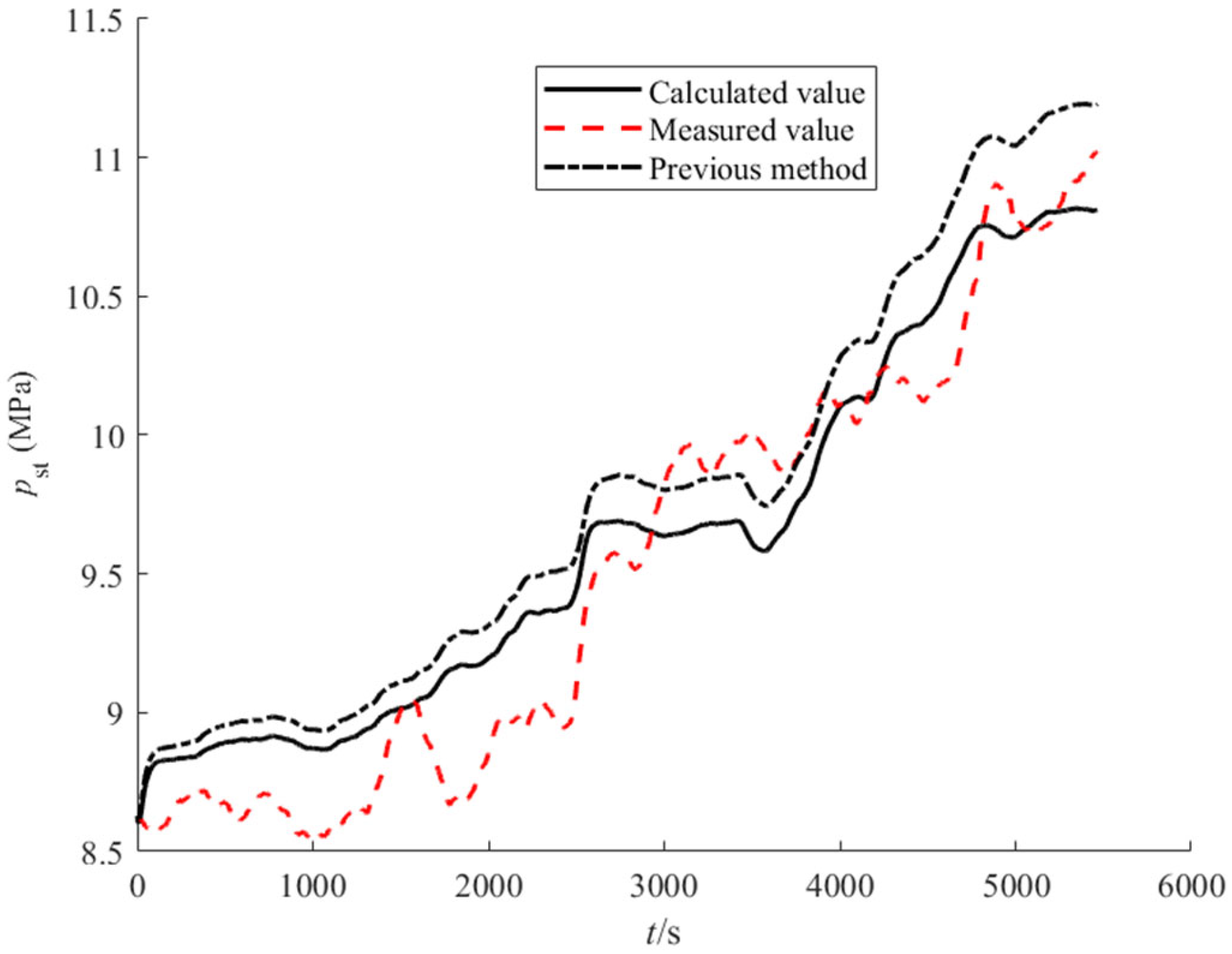
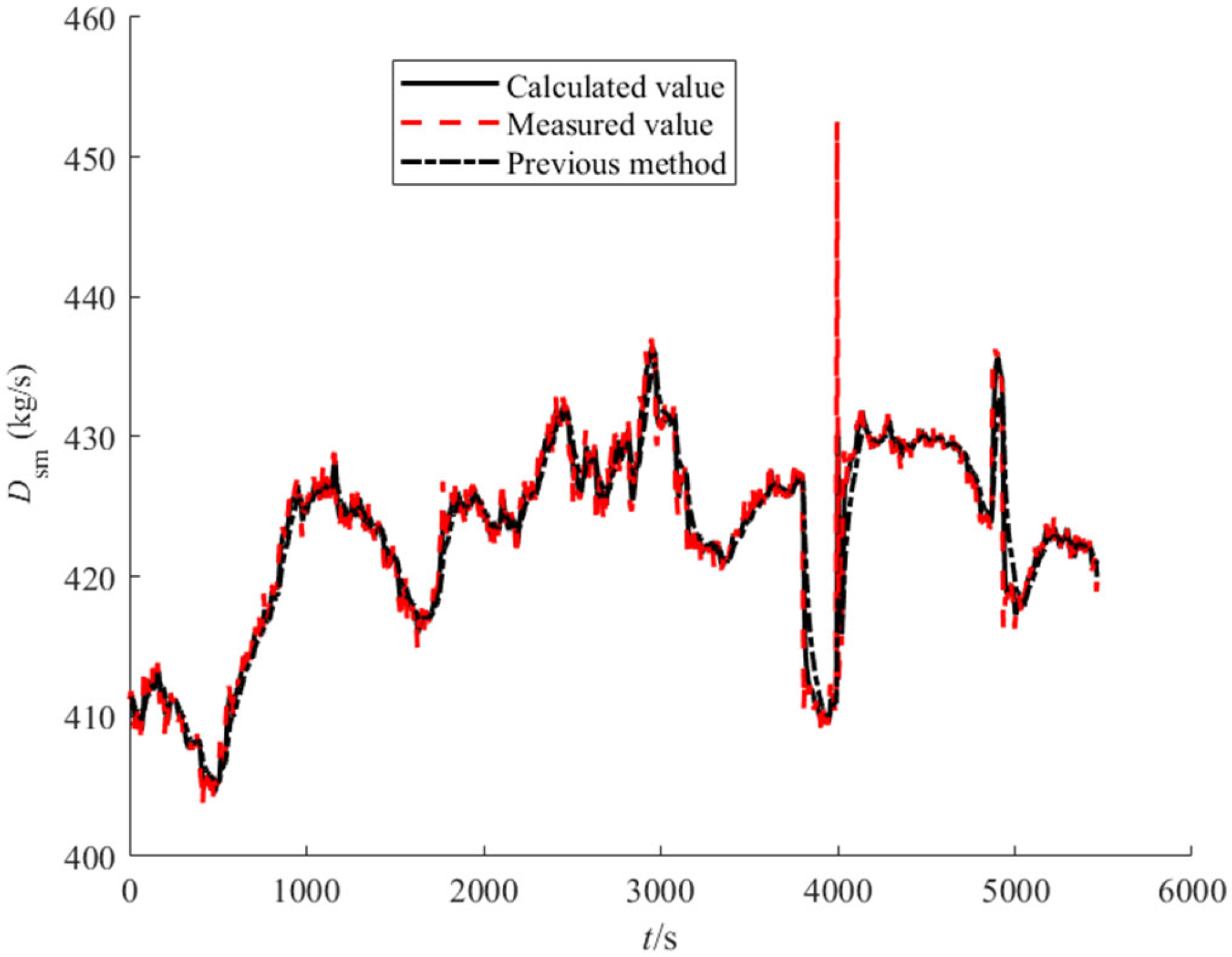
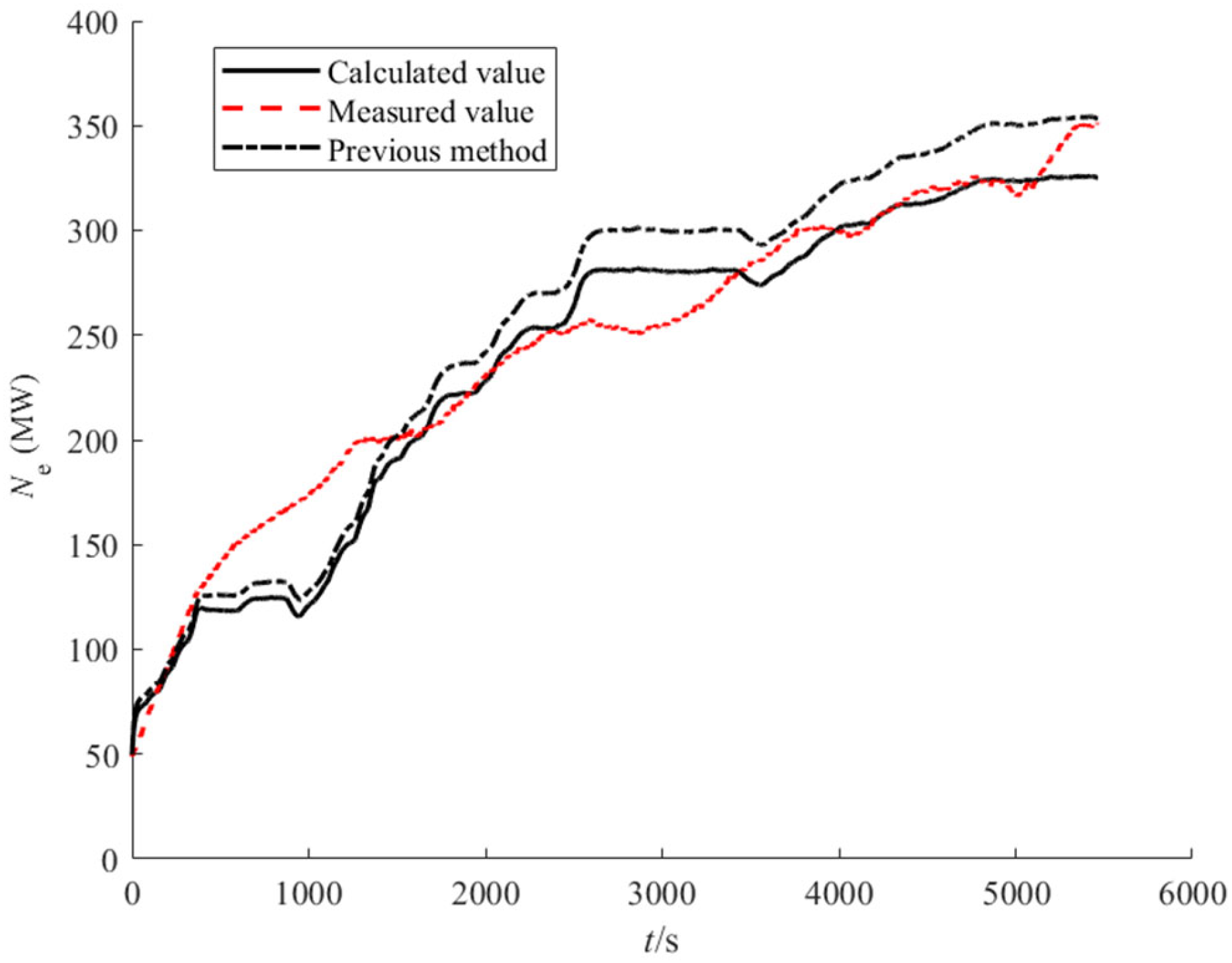
Since this data set lacks multiple steady-state data segments, only dynamic validation of the model is necessary. The selected data, ranging from 50 MW to 350 MW, effectively describe the operational process of the BTCCS in the OTB coal-fired unit under wet conditions, capturing a wide range of load changes. The sampling interval is 1 s. The previous method [9] was used also to validate the modeling performance of the proposed method. Figure 4, Figure 5, Figure 6 and Figure 7 illustrate the variation curves of the system output, while, by comparison, Table 3 provides the root mean square error (RMSE) and the mean relative error (MRE) of system output variables.
As illustrated in Figure 4, Figure 5, Figure 6 and Figure 7, the model’s simulation values can track the actual operational values well, maintaining the same trend when the unit operates under wet variable load conditions ranging from 50 MW to 350 MW. In Table 3, the MREs of the system output variables are all less than 7.5%, and the RMSEs of the system output, p s t , D s m , H , and N e , are less than 0.245 MPa, 1.35 kg/s, 0.25 m, and 20.5 MW, respectively. For the previous method [9], the MREs of the output variables, pst, Dsm, H, and Ne, are 3.15%, 0.28%, 9.3%, and 10.02%, respectively, and the RMSEs of the output variables are 0.33 MPa, 2.09 kg/s, 1.28 m, and 26.1 MW, respectively. Obviously, the proposed method has higher dynamic accuracy by comparison with the previous method [9], and the relevant reasons are analyzed. Compared with the previous method [9], this work adopts dynamic running data in a wide-load range to identify the steady parameters and nonlinear functions by choosing unit load interval points, and thus the proposed method can make full use of dynamic running data to improve the identification accuracy of the parameters and functions. Therefore, by comparison with the previous method [9], the model developed in this work can better model performance. As shown in tables and figures, the results demonstrate that the proposed model can accurately represent the BTCCS process across a wide range of variable load operations under the wet conditions. But there still exist inevitable modeling errors, and the relevant reasons are presented below.
Firstly, the running data have validated the modeling accuracy of the model developed, but the assumptions can reduce the dynamic accuracy of the model due to the lack of detailed mechanism analysis. In addition, the physical parameters in model are time-varying coefficients in practice, and thus the fixed parameters in model may increase dynamic modeling errors when a new group of running data is used to validate the dynamic accuracy. Due to the reliable physical structure, dynamic responses of the model accord with operational experience.

5.2. Model Dynamic Characterization and Validation

In this section, open-loop simulation tests of the system model are conducted to analyze its dynamic characteristics and verify the accuracy of the model structure. Figure 8, Figure 9, Figure 10 and Figure 11 present the open-loop response curves of the system model.
As shown in Figure 8, an increase in the amount of pulverized coal fed into the boiler leads to a rise in the heat release within the boiler chamber. Consequently, the working fluid in the economizer and water wall absorbs more heat, generating a greater amount of saturated steam. This results in a gradual increase in both the main steam pressure and the unit power output. Since the flow rate of the feedwater pump and boiler water circulating pump remain constant, the flow rate of working fluid at the economizer inlet does not change. However, the increased boiler heat load causes the dryness of the working fluid at the water-wall outlet to rise, reducing the amount of fluid entering the water storage tank. As a result, the water level of the water storage tank gradually decreases to the zero-meter level.
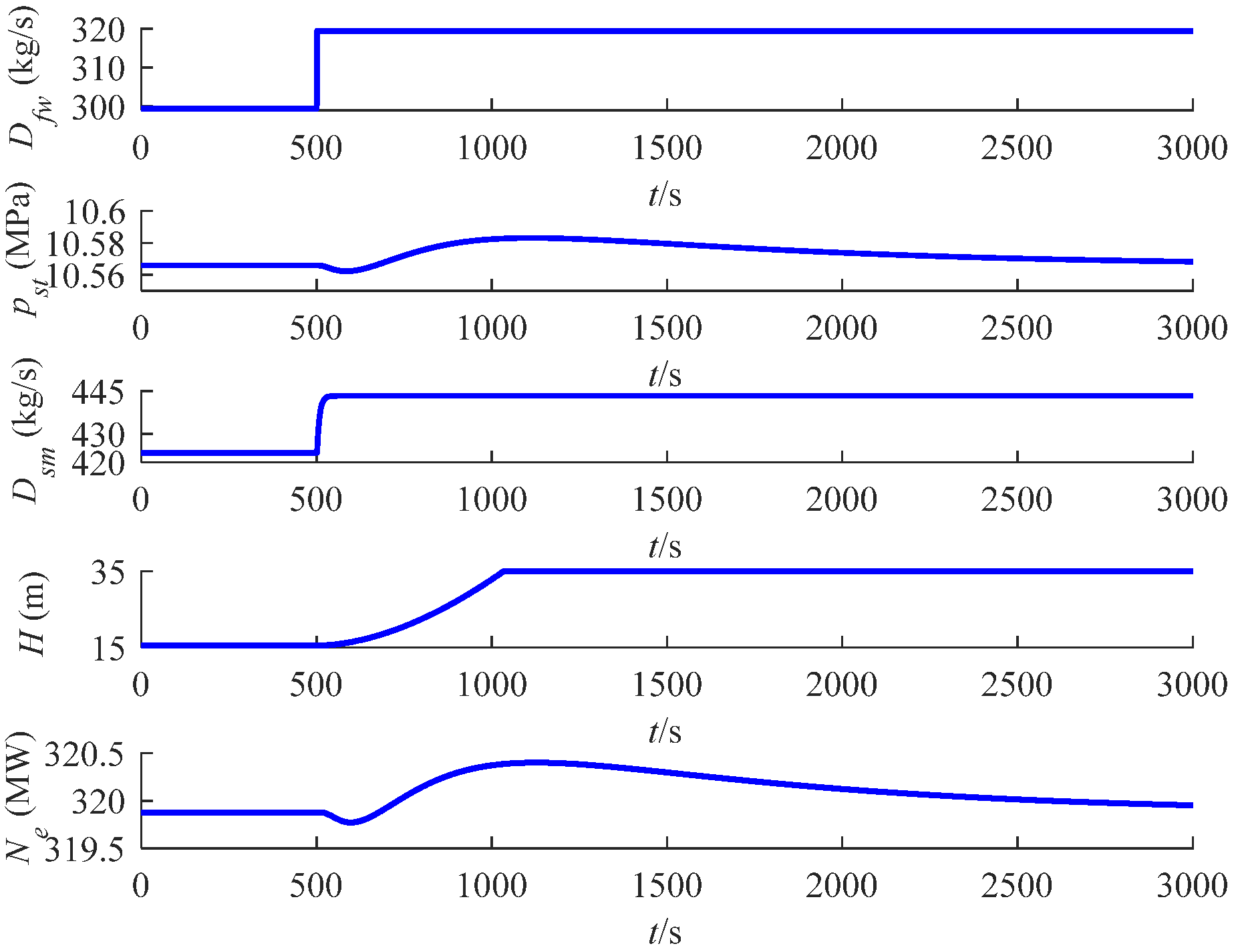
As depicted in Figure 9, a step increases in the feedwater pump flow rate results in an immediate rise in the working fluid flow rate entering the economizer. Consequently, the working fluid within the economizer and water wall becomes compressed. Despite the coal feed rate remaining constant, the total mass of the working fluid in the economizer and water wall increases. This causes fluctuations in the flow rate of the working fluid at the water-wall outlet, leading to minor fluctuations in both the main steam pressure and unit power.
Furthermore, the increased feedwater pump flow rate results in a greater mass of working fluid being stored in the economizer and water wall. Consequently, the steam dryness at the water-wall outlet decreases, and the flow rate of the working fluid entering the storage tank increases. Despite this, the flow rate of the boiler water circulating pump remains constant, causing the water level in the storage tank to gradually rise to its maximum capacity.
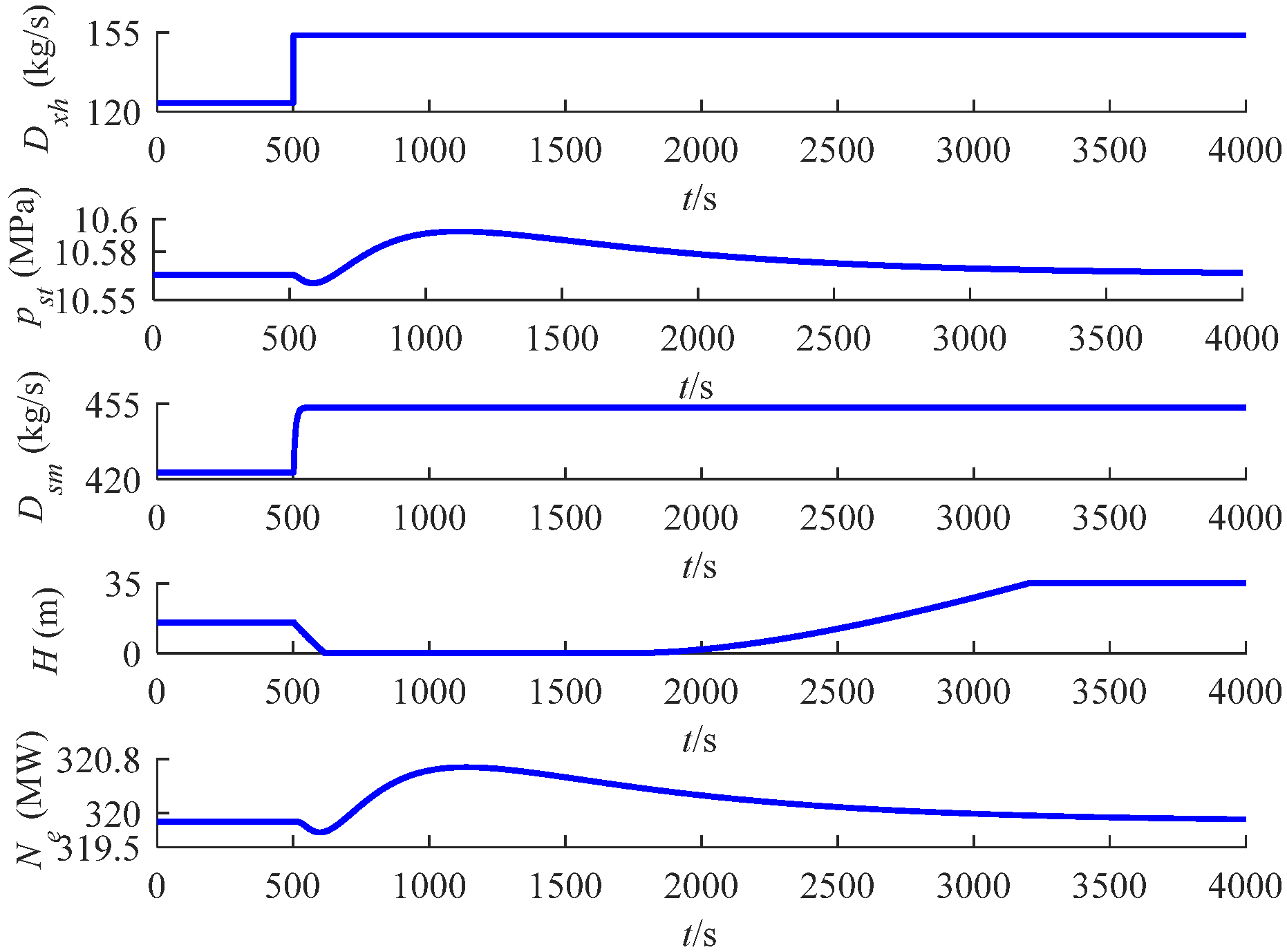
As illustrated in Figure 10, a step increases in the boiler water circulating pump flow rate causes an immediate rise in the inlet working fluid flow rate of the economizer. This results in the compression of the working fluid within the economizer and water wall, while the coal feed rate remains constant. Consequently, the total mass of the working fluid in these components increases, leading to fluctuations in the flow rate at the water-wall outlet. These fluctuations cause minor variations in the main steam pressure and unit power. Regarding the water storage tank, its water level initially decreases as the circulating pump flow rate increases in steps. However, as the feedwater flow into the economizer inlet rises and the steam dryness at the water-wall outlet decreases, the flow of working fluid into the storage tank increases, causing the water level to gradually rise to its maximum capacity.
As depicted in Figure 11, when the steam turbine valve opening decreases in steps, the main steam flow area reduces, causing a gradual increase in the main steam pressure. With the feedwater pump and boiler water circulating pump flow rates held constant, the inlet working fluid flow rate of the economizer remains unchanged. A step increase in main steam pressure leads to an increase in the stored mass of working fluid within the boiler tube wall, resulting in an immediate decrease in the superheated steam flow and a corresponding drop-in unit load, despite the coal feed rate remaining constant. As the main steam pressure stabilizes, the superheated steam flow rate will gradually increase and stabilize, allowing the unit power to return to a steady state. Regarding the storage tank level, the sudden reduction in valve opening causes a decrease in the working fluid flow rate, leading to a reduced outlet flow rate from the water wall and a subsequent decrease in the flow rate into the storage tank, which lowers the water level. However, as the boiler steam pressure rises, the steam dryness decreases, causing an increase in the saturated water entering the storage tank, which gradually raises the water level to its maximum.
In summary, the analysis of the system’s dynamic characteristics reveals that the dynamic response curves in Figure 8, Figure 9, Figure 10 and Figure 11 align well with the operational characteristics of the unit. This congruence confirms the accuracy of the constructed model and parameter structure.

6. Conclusions

A lumped-parameter, mechanism-based dynamic model of the BTCCS for a wet-mode OTB coal-fired unit was established using mass and energy conservation principles. A mechanism-integrated parameter identification method was developed to determine both static and dynamic parameters from variable-load operational data. Validation results show that the model can describe the operational process across 50–350 MW with a mean relative error less than 7.5%, accurately reproduce system dynamics, and capture the essential open-loop dynamic characteristics. These findings confirm the structural correctness of the model and its applicability for simulation analysis and control system design, supporting enhanced flexibility and safety in wet-mode OTB coal-fired unit operation.
There still exist some limits on the dynamic modeling, presented as below:
Firstly, there exist simplification and assumptions on mechanism analysis of OTB coal-fired units under wet mode operation, and these assumptions may affect the accuracy of the dynamic characteristics derived from mechanism structure.
Secondly, there exist inevitable dynamic modeling errors, and these errors should be further decreased to improve the modeling performance.
In future, there exist some research directions on modeling for OTB coal-fired units. Firstly, machine learning methods are required to combine the lumped-parameter method in order to improve dynamic performances of thermal systems. Secondly, it is essential to explore the dynamic characteristics of OTB coal-fired units under full conditions. Thirdly, advanced control algorithms are required to design the CCS of OTB coal-fired units based on the model developed in order to improve operational safety and flexibility of the units operating under wet condition.

Author Contributions

Conceptualization, H.F. and G.Y.; methodology, H.F.; software, H.F.; validation, H.F. and Y.W. (Yongzhen Wang); formal analysis, H.F. and W.S.; investigation, Z.H. and G.C.; resources, M.X.; data curation, Z.Z. and X.S.; writing—original draft preparation, H.F. and Y.W. (Yongzhen Wang); writing—review and editing, Y.L., K.Z., Y.W. (Yuhan Wang), and X.P.; visualization, Y.W. (Yuhan Wang) and H.Z. (Hengrui Zhang); supervision, H.Z. (Huaichun Zhou); project administration, X.P.; funding acquisition, X.P. All authors have read and agreed to the published version of the manuscript.

Funding

This work was supported by the Open Project Program of the State Key Laboratory of Low-Carbon Smart Coal-Fired Power Generation and Ultra-Clean Emission [grant number: D2022FK105], and the National Natural Science Foundation of China (NSFC) [grant number: 52574291], and the Basic Research Program of Xuzhou [grant number: KC23050].

Data Availability Statement

The original contributions presented in the study are included in the article; further inquiries can be directed to the corresponding author.

Acknowledgments

The authors acknowledge the engineers of Yudian Thermal Power Plant and China Resources Tongshan Power Plant for their support in data collection and on-site technical guidance.

Conflicts of Interest

Author Ge Yin was employed by the State Key Laboratory of Low-Carbon Smart Coal-Fired Power Generation and Ultra-Clean Emission, and the China Energy Science and Technology Research Institute Co., Ltd. Authors He Fan, Xianyong Peng, and Huaichun Zhou were employed by the Jiangsu Provincial Engineering Research Center for Smart Energy Technology and Equipment, China University of Mining and Technology. The remaining authors declare that the research was conducted in the absence of any commercial or financial relationships that could be construed as a potential conflict of interest.

References

  1. Wu, C.L.; Wang, C.; Hou, Z.Y.; Wang, Z. Flexible peak shaving in coal-fired power plants: A comprehensive review of current challenges, recent advances, and future perspectives. Energy 2025, 327, 136446. [Google Scholar] [CrossRef]
  2. Sun, F.; Ji, J.X.; Zeng, G.; Li, J.L.; Wei, G.S. Employment of molten salt thermal energy storage coupled to coal-fired power unit for power grid peak shaving: A thermodynamic study. J. Energy Storage 2025, 131, 117503. [Google Scholar] [CrossRef]
  3. Esmaeili, M.; Moradi, H. Robust & nonlinear control of an ultra-supercritical coal fired once-through boiler-turbine unit in order to optimize the uncertain problem. Energy 2023, 282, 128312. [Google Scholar] [CrossRef]
  4. Gao, Z.; Lv, J.H.; Qv, X.F.; Ge, H. Research on Modeling of a Fully Loaded Ultra-supercritical Boiler-Turbine Coordination System. Power Equip. 2021, 35, 201–206. (In Chinese) [Google Scholar] [CrossRef]
  5. Wang, G.T.; Du, M.; Zhang, T.; Wu, Z. Research on Coordinated System Model and Control Strategy of Thermal Power Unit under Wet Operation. J. Eng. Therm. Energy Power 2022, 37, 25–32. (In Chinese) [Google Scholar] [CrossRef]
  6. Liu, Z.F.; Wang, C.Y.; Fan, M.Y.; Wang, Z.; Fang, F.; Liu, M.; Yan, J.J. Investigation on the allowable load ramping-up rate and wet-to-dry conversion time of a 660 MW supercritical coal-fired power plant with deep peak-shaving work conditions. Energy 2025, 314, 134200. [Google Scholar] [CrossRef]
  7. Hentschel, J.; Zindler, H.; Spliethoff, H. Modelling and transient simulation of a supercritical coal-fired power plant: Dynamic response to extended secondary control power output. Energy 2017, 137, 927–940. [Google Scholar] [CrossRef]
  8. Sarda, P.; Hedrick, E.; Reynolds, K.; Bhattacharyya, D.; Stephen, E.Z.; Omell, B. Development of a Dynamic Model and Control System for Load-Following Studies of Supercritical Pulverized Coal Power Plants. Processes 2018, 6, 226. [Google Scholar] [CrossRef]
  9. Liu, J.Z.; Yan, S.; Zeng, D.L.; Hu, Y.; Lv, Y. A dynamic model used for controller design of a coal fired once-through boiler-turbine unit. Energy 2015, 93, 2069–2078. [Google Scholar] [CrossRef]
  10. Liang, Q.J.; Liu, J.Z.; Xue, Y.G.; Yan, S.; Zeng, D.L. A Non-linear Model for Ultra-supercritical Power Unit and the Dynamic Characteristic Study. J. Chin. Soc. Power Eng. 2012, 32, 118–123. (In Chinese) [Google Scholar] [CrossRef]
  11. Qin, Z.M.; Liu, J.Z.; Zhang, L.Y.; Gu, J.J. A Simplified Nonlinear Dynamic Model for Once-through Boiler Units. J. Chin. Soc. Power Eng. 2013, 33, 955–961. (In Chinese) [Google Scholar]
  12. Yan, S.; Zeng, D.; Liu, J.; Liang, Q. A simplified non-linear model of a once-through boiler-turbine unit and its application. Proc. CSEE 2012, 32, 126–134. (In Chinese) [Google Scholar] [CrossRef]
  13. Niu, Y.G.; Du, M.; Ge, W.C.; Luo, H.H.; Zhou, G.P. A dynamic nonlinear model for a once-through boiler-turbine unit in low load. Appl. Therm. Eng. 2019, 161, 113880. [Google Scholar] [CrossRef]
  14. Tian, L.; Lian, H.; Liu, X.; Liu, J. Coupling Characteristics of Steam Pressure and Intermediate Point Temperature for Once-through Boiler. Proc. CSEE 2017, 37, 1142–1150. (In Chinese) [Google Scholar] [CrossRef]
  15. Zhou, H.; Liu, C.K.; Liu, Z.W.; Hu, W.S. Temperature Control via Affine Nonlinear Systems for Intermediate Point of Supercritical Once-Through Boiler Units. Math. Probl. Eng. 2014, 2014, 873142. [Google Scholar] [CrossRef]
  16. Go, G.; Moon, U.C. A Water-Wall Model of Supercritical Once-Through Boilers Using Lumped Parameter Method. J. Electr. Eng. Technol. 2014, 9, 1900–1908. [Google Scholar] [CrossRef]
  17. Xie, Y.; Liu, J.Z.; Zeng, D.L.; Hu, Y.; Zhu, Y.S.; Li, R.L. A dynamic mathematical model used for controller design of a supercritical once-through boiler-turbine unit in all load conditions. Appl. Therm. Eng. 2024, 248, 123139. [Google Scholar] [CrossRef]
  18. Tian, Z.; Yuan, J.Q.; Zhang, X.; Kong, L.; Wang, J.C. Modeling and sliding mode predictive control of the ultra-supercritical boiler-turbine system with uncertainties and input constraints. ISA Trans. 2018, 76, 43–56. [Google Scholar] [CrossRef]
  19. Xie, Y.; Liu, J.-Z.; Zeng, D.-L.; Hu, Y.; Li, R.-L.; Zhu, Y.-S. A dynamic hybrid model of supercritical once-through boiler-turbine unit including recirculation mode and once-through mode. Energy 2024, 309, 132941. [Google Scholar] [CrossRef]
  20. Deng, K.J.; Yang, C.; Chen, H.; Zhou, N.N.; Huang, S.L. Start-Up and dynamic processes simulation of supercritical once-through boiler. Appl. Therm. Eng. 2017, 115, 937–946. [Google Scholar] [CrossRef]
  21. Zhang, H.F.; Gao, M.M.; Fan, H.H.; Zhang, K.P.; Zhang, J.H. A dynamic model for supercritical once-through circulating fluidized bed boiler-turbine units. Energy 2022, 241, 122914. [Google Scholar] [CrossRef]
  22. Fan, H.; Zhang, Y.F.; Su, Z.G.; Wang, B. A dynamic mathematical model of an ultra-supercritical coal fired once-through boiler-turbine unit. Appl. Energy 2017, 189, 654–666. [Google Scholar] [CrossRef]
  23. Fan, H.; Su, Z.G.; Wang, P.H.; Lee, K.Y. A dynamic nonlinear model for a wide-load range operation of ultra-supercritical once-through boiler-turbine units. Energy 2021, 226, 120425. [Google Scholar] [CrossRef]
  24. Fan, H.; Su, Z.-G.; Wang, P.-H.; Lee, K.Y. A dynamic mathematical model for once-through boiler-turbine units with superheated steam temperature. Appl. Therm. Eng. 2020, 170, 114912. [Google Scholar] [CrossRef]
  25. Haddad, A.; Mohamed, O.; Zahlan, M.; Wang, J. Parameter identification of a highly promising cleaner coal power station. J. Clean. Prod. 2021, 326, 129323. [Google Scholar] [CrossRef]
  26. Taler, J.; Zima, W.; Ocłoń, P.; Gradziel, S.; Taler, D.; Cebula, A.; Jaremkiewicz, M.; Korzen, A.; Cisek, P.; Kaczmarski, K.; et al. Mathematical model of a supercritical power boiler for simulating rapid changes in boiler thermal loading. Energy 2019, 175, 580–592. [Google Scholar] [CrossRef]
  27. Ghaffari, A.; Chaibakhsh, A.; Lucas, C. Soft computing approach for modeling power plant with a once-through boiler. Eng. Appl. Artif. Intell. 2007, 20, 809–819. [Google Scholar] [CrossRef]
  28. Liu, X.J.; Kong, X.B.; Hou, G.L.; Wang, J.H. Modeling of a 1000 MW power plant ultra super-critical boiler system using fuzzy-neural network methods. Energy Convers. Manag. 2013, 65, 518–527. [Google Scholar] [CrossRef]
  29. Liu, X.J.; Zhang, H.; Niu, Y.G.; Zeng, D.L.; Liu, J.Z.; Kong, X.B.; Lee, K.Y. Modeling of an ultra-supercritical boiler-turbine system with stacked denoising auto-encoder and long short-term memory network. Inf. Sci. 2020, 525, 134–152. [Google Scholar] [CrossRef]
  30. Huang, C.Z.; Li, Z.Y. Data-driven modeling of ultra-supercritical unit coordinated control system by improved transformer network. Energy 2023, 266, 126473. [Google Scholar] [CrossRef]
  31. Zhu, H.Y.; Tan, P.; He, Z.Q.; Zhang, C.; Fang, Q.Y.; Chen, G. Nonlinear model predictive control of USC boiler-turbine power units in flexible operations via input convex neural network. Energy 2022, 255, 124486. [Google Scholar] [CrossRef]
  32. Hou, G.L.; Du, H.; Yang, Y.; Huang, C.Z.; Zhang, J.H. Coordinated control system modelling of ultra-supercritical unit based on a new T-S fuzzy structure. ISA Trans. 2018, 74, 120–133. [Google Scholar] [CrossRef]
  33. Hou, G.L.; Gong, L.J.; Huang, C.Z.; Zhang, J.H. Novel fuzzy modeling and energy-saving predictive control of coordinated control system in 1000 MW ultra-supercritical unit. ISA Trans. 2019, 86, 48–61. [Google Scholar] [CrossRef]
  34. Hou, G.L.; Xiong, J.; Zhou, G.P.; Gong, L.J.; Huang, C.Z.; Wang, S.J. Coordinated control system modeling of ultra-supercritical unit based on a new fuzzy neural network. Energy 2021, 234, 121231. [Google Scholar] [CrossRef]
  35. Lee, K.Y.; Van Sickel, J.H.; Hoffman, J.A.; Jung, W.H.; Kim, S.H. Controller Design for a Large-Scale Ultrasupercritical Once-Through Boiler Power Plant. IEEE Trans. Energy Convers. 2010, 25, 1063–1070. [Google Scholar] [CrossRef]
  36. Dai, B.W.; Chang, Y.Q.; Xu, S.; Wang, F.L. Process Knowledge-Guided Optimization Control for Once-Through Boiler-Turbine Units Based on Multi-Agent Reinforcement Learning. ACS Omega 2025, 10, 14844–14857. [Google Scholar] [CrossRef]
  37. Huang, C.Z.; Sheng, X.X. Data-driven model identification of boiler-turbine coupled process in 1000 MW ultra-supercritical unit by improved bird swarm algorithm. Energy 2020, 205, 118009. [Google Scholar] [CrossRef]
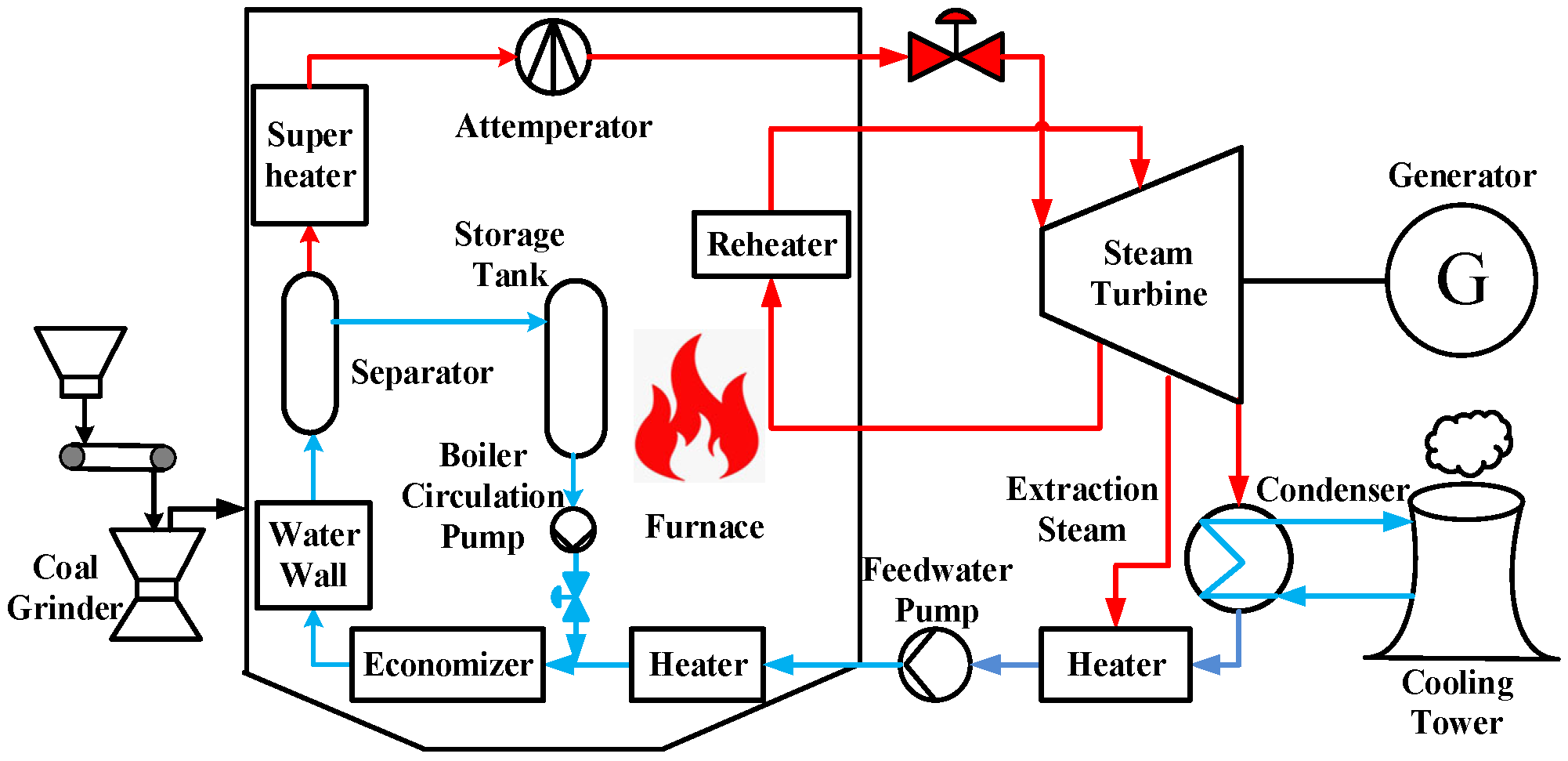
Figure 1. Schematic diagram of the operation process of the USC unit under wet conditions (red line: water steam; blue line: liquid water; black line: coal combustion).
Processes 13 03625 g001
Figure 2. Schematic diagram of the model of BTCCS for USC units under wet conditions (solid line: strong correlation; dashed line: weak correlation).
Processes 13 03625 g002
Figure 3. Flowchart of the mechanism-integrated parameter identification method.
Processes 13 03625 g003
Figure 4. Main steam pressure response curve under wet variable load conditions of the unit.
Processes 13 03625 g004
Figure 5. Economizer inlet working fluid response curve under wet variable load conditions of the unit.
Processes 13 03625 g005
Figure 6. Water level response curve of water storage tank under wet variable load conditions of the unit.
Processes 13 03625 g006
Figure 7. Unit power response curve under wet variable load conditions of the unit.
Processes 13 03625 g007
Figure 8. Response curve of system output variables after step increase in fuel demand command.
Processes 13 03625 g008
Figure 9. Response curve of system output variable after step increase in feedwater pump flow rate.
Processes 13 03625 g009
Figure 10. Response curve of system output variable after step increase in boiler water circulating pump flow rate.
Processes 13 03625 g010
Figure 11. Response curve of system output variable after step reduction in steam turbine valve opening.
Processes 13 03625 g011
Table 1. Main operational parameters of the unit under the condition of maximum continuous evaporation of the boiler.
ProjectValue
Unit load (MW)1000
Superheated steam flow (t/h)3044
Superheated steam temperature (°C)605
Superheated steam pressure (MPa)27.46
Feedwater temperature (°C)297
Reheat steam flow (t/h)2544
Reheater outlet steam temperature (°C)603
Storage tank height (m)35
Storage tank bottom diameter (m)0.61
Table 2. System variables corresponding to each unit load point.
Ne
(MW)
pst
(MPa)
H
(m)
Dsm
(kg/s)
uB
(kg/s)
Dfw
(kg/s)
Dxh
(kg/s)
utDst
(kg/s)
pm
(MPa)
hst
(kJ/kg)
0.8198.714.13399.532.3218.7180.61213.78.933283.9
50.428.6212.62411.3835.9249.1162.31243.18.913195.9
100.28.6812.02411.237.3247.0164.312469.003200.5
150.58.624.44411.538.2251.7159.81249.58.953205.8
200.368.8312.75422.441.4239.6182.71239.99.193263.4
251.38.9712.7431.045.6263.4167.61262.69.493308.3
300.710.110.6413.848.4293.3120.71298.410.643252.7
350.41112.5421.750.3316.5105.21315.811.553299.4
Table 3. RMSE and MRE of system output variables.
Indicatorpst (MPa)Dsm (kg/s)H (m)Ne (MW)
Proposed
method
MRE (%)2.310.141.867.42
RMSE0.2451.310.2220.43
Previous
method
MRE (%)3.150.289.310.02
RMSE0.332.091.2826.09
Disclaimer/Publisher’s Note: The statements, opinions and data contained in all publications are solely those of the individual author(s) and contributor(s) and not of MDPI and/or the editor(s). MDPI and/or the editor(s) disclaim responsibility for any injury to people or property resulting from any ideas, methods, instructions or products referred to in the content.