Abstract
Multi-slice mining of the 70 m ultra-thick coal seam in East Junggar coalfield, China is marked by large-scale mining space expansion and frequent stress disturbances. To address those, this study uses theoretical analysis, physical simulation, and numerical simulation to explore the evolution of an overburden bearing structure and the control of strata behavior in multi-slice mining. The results (1) clarify the overburden fracture-hinging characteristics: fractured blocks in lower hard strata form beam-type hinges (early stage), the lower hinged structure weakens and the beam-type hinge structure moves upward in steps (middle stage), the continuous increase in the mined-out space leads to the transverse O-X fracture of far-stope rock strata, and broken rock blocks are extruded into shells (late stage); this study also proposes an identification method for the morphology of roof bearing structures (including beam structure, higher beam structure, and arch structure); (2) define the support-controlled strata range and load calculation method at different stages, and show that the support load “increases slowly under the near-stope roof bearing structure and tends to stabilize under the far-stope roof bearing structure” as the roof bearing structure moves upward; and (3) guided by the aims of avoiding cantilever beams and ensuring near-stope roof stability, lead us to propose the following measures: pre-splitting main roof (early stage); short working faces with reduced layered thickness and rapid advance (late stage); and goaf/separation grouting (whole process). The maximum support load drops from 20,017.5 kN to 16,192.5 kN, enabling lightweight support selection. This study provides theoretical guidance for support selection and roof control in the multi-slice mining of ultra-thick coal seams.
1. Introduction
With the construction of a 100-million-ton coal base in Xinjiang of China, scientific and efficient mining of an integrated coalfield with ultra-thick coal seams has become the development trend of coal mining in the region. Ultra-thick coal seams are widely distributed in the world. However, open-pit mining is generally the main method for mining them [1], with limited experience in underground mining. Underground coal mines in Xinjiang that host ultra-thick coal seam deposits are about to witness or have entered the stage of first-slice mining. However, due to the unclear research on the strata pressure behavioral characteristics in the stope during the entire process of ultra-thick coal seam multi-slice mining, especially those 70 m thick, the stope roof strata control, support selection, and mining parameter design lack effective support. As a result, some mines are facing problems such as intense strata pressure behavior and an excessive support load during production. Therefore, it is urgently necessary to conduct research on the strata pressure behavior laws and the stability control of the roof bearing structure under the conditions of a large-scale mining volume and multi-mining disturbances in the multi-slice mining of the ultra-thick coal seam in this area.
In recent years, systematic research studies have been conducted focusing on the law of overburden strata breakage movement [2,3], along with the characteristics and control measures of strata pressure [4,5] in thick-seam and close-seam group mining. The research results can provide a useful reference for the study of roof control technology in multi-slice mining of ultra-thick seams.
- (1)
- By means of theoretical analysis, simulation experiments, and field measurement, the characteristics of fracture development and stress distribution in overburden strata under multi-mining of an ultra-thick coal seam and close-distance coal seam group are systematically studied. For example, through numerical simulation and field measurement, Likar Jakob et al. and Chen Haidong et al. studied the change characteristics of stress distribution in ultra-thick coal seam multi-slice mining, which provided guidance for determining reasonable mining parameters [6,7,8]. Additionally, Kang Yonghua et al. and Wang Xiaolei et al. studied the development characteristics of mining fissures in thick coal seam multi-mining by theoretical analysis and field measurement, and they fitted out the empirical formula of overburden fracture height. It was put forward that a reasonable reduction in slicing mining thickness is conducive to controlling the development of overburden fractures [9,10]. Ning Jianguo et al. established the mechanical model for a second activation of fractured overlying strata in close-distance coal seam group mining, and they proposed a method for predicting the height of the fractured zone [11]. Through physical simulation experiments and field measurements, Yang Xuelin et al. studied the periodic evolution of surface subsidence and surface cracks in shallow-buried close-distance multi-seam mining, providing guidance for surface subsidence control under multiple disturbance [12].
- (2)
- By establishing a mechanical model of a roof bearing structure in thick coal seam mining, the relationship between the support and the surrounding rock in large-scale mining space is clarified. Based on voussoir beam theory [13], Lan Yiwen et al., by establishing the roof bearing structure mechanics model in the large-scale mining space of a “cantilever beam–voussoir beam–high rock stratum”, analyzed the mechanism of mining pressure when the periodic weighting distance and strength presented small–big–small–big periodical change characteristics in thick coal seam mining [14]. Shi Jiulin et al. established a mechanical model for the composite overlying structure of a “lower combined cantilever structure–middle combined cantilever structure–upper hinged structure” in the mining of thick coal seams, clarified the characteristics of “small to medium to large” mining pressure in the mining area, and proposed corresponding roof pre-splitting technology [15]. Lv Huayong et al. studied the impact of coal seam burial depth, medium layer thickness, and its location on the top-coal movement and pressure distribution under high-intensity repeated mining, and they clarified the reasonable position of the first mining face in the middle and lower layers [16]. Majid Khan and Liang Shun summarized the mining space of thick coal seams as “four zones, three arches, and five zones” based on on-site drilling and microseismic event measurements, and they proposed a comprehensive warning method for mining field strength and pressure manifestation [17,18]. Wang Feng et al. established a mechanical model of fracture and instability of the key stratum and voussoir beam structure based on the arch structure in the unconsolidated layers, and they studied the characteristics of overburden movement and the support load under different roof bearing structures, providing a new idea for support load calculation [19].
- (3)
- Based on the influence factors of roof bearing structural stability, technical measures for controlling overburden movement in extra-thick coal seam mining are put forward. Aiming at solving the problem of strong strata pressure appearing in extra-thick seam mining under the thick and hard roof in the Datong mining area, Yu Bin et al. and Zhu Weibing et al. constructed the large structural mechanics model of a “cantilever beam and voussoir beam” in the near-field key stratum and the “triangle plate” in they far-field key stratum [20,21,22]. Countermeasures of strata pressure control, such as pre-splitting key strata [23], fixed-point grouting in overburden, and control of working face advance speed, are put forward. Deng Xuejie et al. and Nay Zarlin et al. studied the characteristics of overburden strata breakage movement in ultra-thick coal seam multi-slice filling mining. It is believed that filling mining can effectively control the development of the overburden plastic zone and reduce the range of strata that are controlled by support [24,25].
To date, there have been improvements in the theoretical studies and engineering practices for the evolution of overburden structure and the mechanism of strata pressure appearance in a thick coal seam and close-distance coal seam group mining. However, there are few studies on the mechanism of strong strata pressure under the condition of a large-scale extraction volume and multi-mining disturbance in ultra-thick coal seam multi-slice mining. Therefore, this paper studies the stability mechanism of different roof bearing structures, the variation characteristics of the support load, and the corresponding control measures, based on the occurrence conditions and the evolution characteristics of the roof bearing structure for a typical ultra-thick coal seam in the East Junggar coalfield [26]. The results will provide guidance and a reference for efficient and safe extraction of an ultra-thick coal seam. However, as the relevant mines are currently only mining the first slice, the strata pressure behavior laws during the multi-slice mining of ultra-thick coal seams lack support from measured data; accordingly, this research will be refined subsequently in accordance with the actual production progress.
2. Evolution Characteristics of Overburden Structure in Multi-Slice Mining of Ultra-Thick Coal Seam
The structural morphology of the overlying strata in the stope determines the characteristics of mine pressure behavior. Understanding the evolution characteristics of the overlying strata structure in multi-slice mining of an ultra-thick coal seam is instrumental for studying and controlling stope mine pressure. This section first investigates the evolution characteristics of the overlying strata structure in ultra-thick coal seam multi-slice mining through simulation experiments. Then, it analyzes the forms of the roof bearing structures corresponding to different overlying strata structures, providing a basis for support load calculation.
2.1. Physical Simulation of Overlying Strata Structural Evolution Under Different Slicing Mining Thicknesses
The location and stratigraphic column of the Dajingnan No. 1 coal mine are shown in Figure 1. The main mining seam is a Group B coal seam with a thickness of 71 m, and the thickness of overlying strata is 310.52 m.
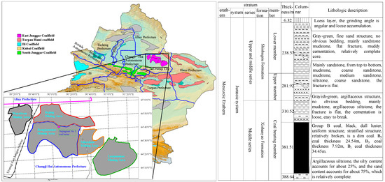
Figure 1.
Location and stratigraphic information of Dajingnan No. 1 coal mine.
The occurrence parameters of a Group B coal seam were optimized, with the overlying strata thickness of 310 m and coal seam thickness of 70 m. The physical model dimensions (length × width × height) are 2.5 m × 0.2 m × 1.62 m, with a geometric similarity ratio of 1:240, time similarity ratio of 15.5, bulk density ratio of 0.6, and stress similarity constant of 160.8. The simulated strength and mix ratio of model materials are shown in Table 1.

Table 1.
Physical and mechanical properties of simulated rock strata and their mix ratio schemes.
Referring to the current mining technology in this area, the ultra-thick coal seam is mined by fully mechanized top-coal caving with downward slicing and caving. The slicing thicknesses are 10 m and 20 m, corresponding to seven and four slicing times, respectively, with the last slicing thickness being 10 m. Since the research objective is the entire overlying strata movement from the coal seam to the surface, the top-coal caving process is not refined here, i.e., the excavation height is the slicing thickness, which is also adopted in subsequent numerical simulations, as shown in Figure 2.

Figure 2.
Similar physical simulation models. (a) Slicing mining thickness 10 m. (b) Slicing mining thickness 20 m.
In the process of multi-slice mining, the roof bearing structure shows the evolution process of “beam structure–higher beam structure–arch structure”, as shown in Figure 3 [26].
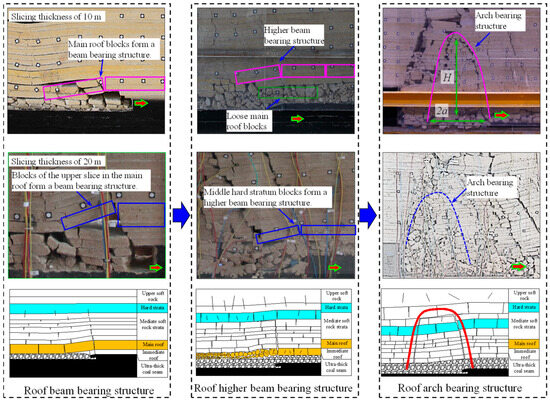
Figure 3.
Evolution process of roof bearing structure in multi-slice mining of ultra-thick coal seam.
With the increase in slicing thickness, the stability of the roof beam bearing structure decreases. When the slicing thickness is 10 m, the main roof breaks and forms a hinged structure in the first-slice mining process. During the second-slice mining, the lower blocks in main roof cave and fill the goaf, and the upper blocks in main roof experience secondary breakage and are hinged to form a beam bearing structure, as shown in Figure 4a. When slicing thickness is 20 m, in the first-slice mining process, the main roof appears to separate, and the lower blocks cave and fill the goaf, the upper blocks break and form a hinged structure, as shown in Figure 4b. In second-slice mining, the main roof blocks do not break again, and the beam bearing structure is unstable.

Figure 4.
Fracture characteristics of main roof at different slicing mining thicknesses. (a) Slicing mining thickness 10 m. (b) Slicing mining thickness 20 m.
2.2. Numerical Simulation of Overlying Strata Structural Evolution Under Different Slicing Mining Thicknesses
Physical simulation analyzes the fracture and movement characteristics of overlying strata in ultra-thick coal seam multi-slice mining from a two-dimensional plane perspective. Based on the model parameters in Section 2.1, this section uses numerical simulation to analyze the evolution characteristics of the overlying strata structure under different slicing thicknesses, verifying, supplementing, and improving the physical simulation results.
The mining space of the ultra-thick coal seam is large, and the overlying strata exhibit two movement states: continuous deformation, with bending and subsidence above the stope, and discontinuous deformation, with fracture and collapse at the fracture line. GPU Continuum-based Discrete Element Method software v.1.0.0.1 (GDEM, GDEM Technology Beijing Co., Ltd., Beijing, China) is based on the Continuum-based Discrete Element Method CDEM (CDEM) of continuum mechanics, which can realize the whole process simulation of material from continuous deformation to fracture movement. Therefore, this section uses GDEM software v.1.0.0.1 to establish a three-dimensional model to study the overlying strata fracture characteristics under different slicing thicknesses. The model selects a 430 m × 700 m × 392 m coal–rock mass from the floor of a Group B coal seam to the surface. The geometric model and the location of hard rock strata are shown in Figure 5.
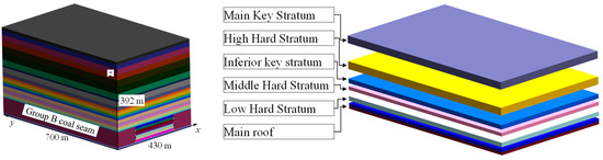
Figure 5.
Numerical models built for the analyses of ultra-thick coal seam slice mining.
The model design: the length along the working face direction is 430 m, the working face width is 220 m, the roadway width is 5 m, and 100 m of solid coal is reserved on both sides to eliminate boundary effects; the length along the working face advance direction is 700 m, the working face advance length is 600 m, and 100 m of solid coal is reserved on the open-off cut side; and the model height is 392 m, which is the thickness of the coal–rock strata from the floor of the Group B coal seam to the surface. Group B coal seam is 70 m thick, and the overlying strata thickness is 312 m. The slicing thicknesses are 10 m and 20 m, respectively. The numerical simulation schemes are shown in Figure 6. The five faces (front, rear, left, right, and bottom) of the model are fixed boundaries, and the top is a free surface, modeled to the surface. The vertical direction is the self-weight stress of rock strata, the lateral pressure coefficient is 0.5, and the constitutive model of coal–rock strata is the Mohr–Coulomb model.
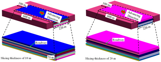
Figure 6.
Schematic diagram of numerical simulation schemes for ultra-thick coal seam multi-slice mining.
The three-dimensional numerical simulation results show that the overlying strata structure in ultra-thick coal seam multi-slice mining exhibits an evolution characteristic of “beam structure–higher beam structure–shell structure”. The different overlying strata structural forms during the multi-slice mining of ultra-thick coal seams are shown in Figure 7: in the early stage of slicing mining, the main roof undergoes periodic vertical O-X fracture to form a beam structure, and fractures appear in the hard rock strata near the stope; in the middle stage of slicing mining, the articulation of main roof rock blocks fails, the fractures in the hard rock strata near the stope penetrate, and periodic vertical O-X fracture occurs to form a higher beam structure, with fractures appearing in the main key stratum; and in the late stage of slicing mining, the fractures in the main key stratum penetrate, and transverse O-X fracture occurs to form a shell structure to bear the overlying strata, separating from the underlying strata. According to the degree and scope of rock block fragmentation, the underlying strata can be divided into two categories: those that can form a higher beam-like bearing structure and those that are completely loose.
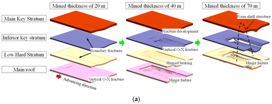
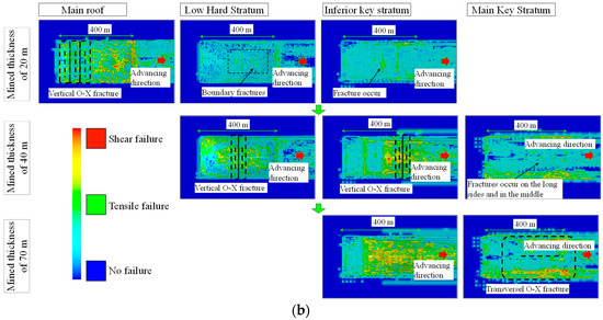
Figure 7.
Overlying strata structure forms in multi-slice mining of ultra-thick coal seam. (a) Overlying strata fracture characteristics. (b) Fracture development characteristics.
2.3. Evolution Process of Overlying Strata Structure in Multi-Slice Mining of Ultra-Thick Coal Seam
In summary, during the multi-slice mining of an ultra-thick coal seam, the overlying strata structure undergoes an evolution process of “beam structure–higher beam structure–shell structure”, as shown in Figure 8.
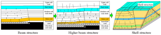
Figure 8.
Evolution process of overlying strata structure in multi-slice mining of ultra-thick coal seam.
Early mining stage: The main roof and the hard rock strata near the stope undergo vertical O-X fracture, the fractured rocks of the main roof achieve effective articulation, fractures appear in other hard rock strata along the mining boundary, the overlying strata structure is a beam structure, and the roof bearing structure is a masonry beam structure formed by the articulation of fractured main roof rocks.
Middle mining stage: The articulation of main roof fractured rocks fails, the upper hard rock strata achieve effective articulation, fractures develop in the main key stratum along the mining boundary, the overlying strata structure is a higher beam structure, and the roof bearing structure is a masonry beam structure formed by the articulation of fractured upper hard rock strata.
Late mining stage: The main key stratum undergoes transverse O-X fracture and the pieces articulate with each other to form a shell structure to bear the overlying strata, the overlying strata structure is a shell structure, and the stope is subjected to the load of the strata under the shell structure. According to the fragmentation degree and scope of the strata near the stope, the strata near the stope can form three types of roof bearing structures: “higher beam bearing structure”, “ higher beam bearing structure + arch bearing structure”, or “ arch bearing structure”.
3. Stability Mechanism of Overlying Strata Structure in Multi-Slice Mining of Ultra-Thick Coal Seam
During the multi-slice mining of an ultra-thick coal seam, the overlying strata beam structure and higher beam structure are essentially masonry beam structures, and the overlying strata shell structure is essentially a three-hinged arch structure formed by the transverse O-X fracture of roof strata. There have been many studies on the stability analysis of masonry beam structures and three-hinged arch structures, which are not discussed in this paper. This section analyzes the stability mechanism of the overlying strata structure from the perspective of the delamination fracturing characteristic of bearing strata in (higher) beam structures and the stability mechanism of a stress arch in shell structures, providing a basis for the calculation of the roof pressure in the slicing mining of ultra-thick coal seams.
3.1. Delamination Fracturing Characteristic of Bearing Strata in Beam Structures
3.1.1. Occurrence Characteristics of Weak Interlayers in Overlying Strata
The physical simulation results of multi-slice mining of an ultra-thick coal seam show that the main roof rocks undergo secondary fracture during the early mining stage, which reduces the stability of the masonry beam structure. The borehole column of a typical mine in the East Junggar mining area shows that the overlying strata of the Group B coal seam are mainly sandstone and mudstone, with a large thickness generally ranging from 10 m to 30 m. When the rock thickness is large, one to three interlayers are generally present, the interlayer lithology is mainly silty mudstone, and the interlayer thickness ranges from 0 m to 3 m. To accurately grasp the occurrence of interlayers in the overlying strata of an ultra-thick coal seam, well logging work was carried out in the Dajing No. 2 coal mine adjacent to the Dajingnan No. 1 coal mine. The borehole distribution of the Dajing No. 2 coal mine is shown in Figure 9.
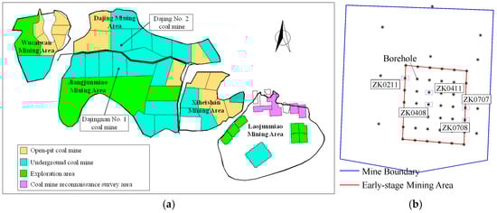
Figure 9.
Borehole distribution of Dajing No. 2 coal mine. (a) Location of Dajing No. 2 coal mine. (b) Borehole distribution.
The well logging methods include density logging (CDN), natural gamma logging (GR), and triple lateral resistivity logging (LL3). The density curve can determine the distribution of coal seams, the natural gamma value is generally positively correlated with the shale content, and the triple lateral resistivity curve can be used for lithology identification. The M552 wall-contact combo tool was run into the borehole by a winch to detect the density, natural gamma, and resistivity. The logging curves of some boreholes are shown in Figure 10.

Figure 10.
Well logging curves of Dajing No. 2 coal mine.
According to the logging curves in Figure 10, there are significant decreases in gamma value in mudstone strata and significant increases in gamma value in sandstone strata, indicating the presence of sandstone interlayers in mudstone strata and mudstone interlayers in sandstone strata. For example, in ZK0707, there is a 11.31 m thick mudstone in the roof of the B1 coal seam, and there is a region with a significant decrease in gamma value (about 2 m) in the middle of the mudstone, indicating a 2 m thick sandstone interlayer. In ZK0408, there is a 1 m region with an increase in gamma value in the upper middle part of the 6.48 m thick fine sandstone in the roof of the B1 coal seam, indicating a mudstone interlayer, and there are multiple regions with significant decreases in gamma value in the 20.65 m silty mudstone above it, indicating multiple interlayers. Mechanical tests show that due to the high shale content, the tensile strength of the siltstone and argillaceous siltstone interlayers in the roof of the B1 coal seam is 0.8~1 MPa, the internal friction angle is 40°, and the cohesion is around 0.7 MPa, which is lower than the empirical value. The internal cohesion of the roof rock of the B1 coal seam is low, the interlayer bonding force is poor, it is easy to slide along the weak interlayer, and the tensile and shear strength is low.
3.1.2. Delamination Fracturing Characteristic of Bearing Strata
The coal-bearing strata of the ultra-thick coal seam are sedimentary rocks. There are structural weak planes or weak interlayers in the thickness direction of thick and hard rock strata. With the advance of the working face, the unsupported length of the thick and hard rock beam increases, and the shear force in the rock beam increases. When the shear force at the structural weak plane exceeds the shear strength, or when the maximum shear force in the beam exceeds the shear strength of the rock beam, the thick and hard rock strata are delaminated, and the fracture step distance of the rock strata decreases. Since the thickness of the roof rock strata of the ultra-thick coal seam is 20~30 m, elastic mechanics are used to analyze the stress in the thick and hard rock beam. The stress on the unsupported part of the thick and hard rock strata during the mining of the ultra-thick coal seam is shown in Figure 11.

Figure 11.
Stress analysis of the unsupported part of thick and hard rock strata.
According to elastic mechanics, the shear stress at any point in the cantilever rock beam under uniform load q can be obtained as follows:
When there is a structural weak plane in the thick and hard rock beam, the condition for the delamination movement of the thick and hard cantilever rock beam is
When the unsupported length of the rock beam satisfies Formula (2), the rock beam begins to be delaminated, where [τ1] is the shear strength of the structural weak plane, y1 is the distance from the structural weak plane to the middle layer of the rock beam, L1 is the unsupported length of the rock beam, q is the uniformly distributed load on the rock beam, h is the thickness of the rock beam, and τxy is the shear stress sustained in the structural weak plane.
When there is no structural weak plane in the thick and hard rock beam, the maximum shear stress of the thick and hard cantilever rock beam occurs in the middle layer. At this time, the delamination movement of the thick and hard cantilever rock beam needs to satisfy Formula (3), where [τ2] is the shear strength of the thick and hard rock beam.
Therefore, the movement of the thick and hard cantilever rock beam during the advance of the working face is shown in Table 2.
Table 2.
Delamination fracturing characteristic of thick–hard rock strata.
Ignoring the effect of horizontal force T on the rock beam, when L1 > L, the thick and hard rock beam fractures directly without delamination, where L refers to the periodic fracture length of the roof; when L1 < L, the thick and hard rock beam is delaminated first, then fractures with the advance of the working face.
For the latter case, when the fracture step distance of the upper slice Lup is less than that of the lower slice Ldown, the upper and lower slices bear the load as a whole before fracture, the periodic fracture step distance is L, and the upper and lower rock strata move independently after fracture. The movement state of each slice is determined according to the stability conditions of the beam bearing structure, and the fractured slice rocks are unstable, permitting them to fill the goaf or form a beam bearing structure. When the fracture step distance of the upper slice Lup is equal to or greater than that of the lower slice Ldown, after the thick and hard rock beam is delaminated, the upper and lower slices fracture and move as independent rock strata.
3.1.3. Fracture and Movement Characteristic of Beam Bearing Structures Under Different Slicing Thicknesses
Based on the above analysis and the occurrence conditions of the ultra-thick coal seam in the Dajingnan No. 1 coal mine, the fracture and movement processes of beam bearing structures under different slicing thicknesses are studied, respectively.
The roof column and related mechanical parameters of the Group B coal seam in the Dajingnan No. 1 coal mine are shown in Table 3. Above the coal seam are a 9.8 m thick immediate roof and a 20 m thick main roof, with a weak interlayer in the middle of the main roof, and the shear strength of the interlayer is 0.2 MPa.
Table 3.
Roof column and rock mechanical parameters of Group B coal seam in Dajingnan No. 1 coal mine.
According to Formula (2), the minimum unsupported length for the main roof to be delaminated is 8.53 m, and the periodic step distance for the whole layer fracture of the main roof is 23 m. Therefore, the main roof is first delaminated along the middle interlayer, then fractures with the advance of the working face. The fracture and movement processes of the main roof under different slicing thicknesses are shown in Figure 12.

Figure 12.
Fracture and movement processes of the main roof under different slicing thicknesses. (a) Slicing mining thickness 10 m. (b) Slicing mining thickness 20 m.
- (a)
- Fracture and movement characteristics of roof beam bearing structure when slicing thickness is 10 m
When the slicing thickness is 10 m, during the first-slice mining, the periodic fracture step distance of the upper and lower slices is 23 m, the bulking factor of the immediate roof is 1.4, the rotational subsidence of the lower slice of the main roof is 6.08 m, the lower slice meets the stability conditions of the masonry beam structure, and the upper and lower slices of the main roof form a beam bearing structure through articulation.
During the second-slice mining, the fracture step distance of the lower slice of the main roof is 18.26 m, the residual bulking factor of the caved blocks of the immediate roof is 1.1, the height from the caved blocks in the goaf to the lower slice of the main roof is 8.04 m, the lower slice of the main roof is unstable due to rotational deformation and collapses to fill the goaf, and the upper slice of the main roof undergoes secondary fracture, breaking into two parts of 13.61 m and 9.39 m, and maintains a beam bearing structure through mutual articulation.
During the third-slice mining, the residual bulking factor of the caved blocks of the immediate roof and the lower slice of the main roof is 1.1, the height from the caved blocks in the goaf to the upper slice of the main roof is 8.02 m, and the upper slice of the main roof is unstable due to rotational deformation.
- (b)
- Fracture and movement characteristics of roof beam bearing structure when slicing thickness is 20 m
When the slicing thickness is 20 m, during the first-slice mining, 3 m of top coal is left, the periodic fracture step distance of the main roof is 23 m, the rotational subsidence of the lower slice is 13.21 m, the lower slice is deformed and unstable, permitting it to collapse and fill the goaf, and the height from the caved blocks in the goaf to the upper slice of the main roof is 8.88 m. The upper slice of the main roof meets the stability conditions of the masonry beam structure and forms a beam bearing structure through mutual articulation.
During the second-slice mining, the upper slice of the main roof breaks into two parts of 13.61 m and 9.39 m, the height from the caved blocks in the goaf to the upper slice of the main roof is 16.52 m, and the upper slice of the main roof collapses to fill the goaf.
In summary, during the first-slice mining of the ultra-thick coal seam, the near-stope thick and hard roof is delaminated, and each slice moves independently after the thick and hard roof fractures. When the filling degree of the goaf decreases, the rotational subsidence of the fractured rocks in the lower slice of the roof increases, leaving them prone to rotational deformation and instability. During the mining of other slices, due to the decrease in the thickness of the hard roof rock strata, the periodic fracture step distance of the upper slice of the roof decreases, resulting in secondary fracture. The formed masonry beam structure has reduced stability or even instability.
3.2. Stability Mechanism of Arch Bearing Structure
In the late stage of slicing mining of an ultra-thick coal seam, with the increase in mining space, the far-stope roof strata undergo transverse O-X fracture to form a shell structure. The strata above this structure form either a “higher beam structure + stress arch structure” or a “stress arch structure” to bear the load of the strata above the stope, as shown in Figure 13.
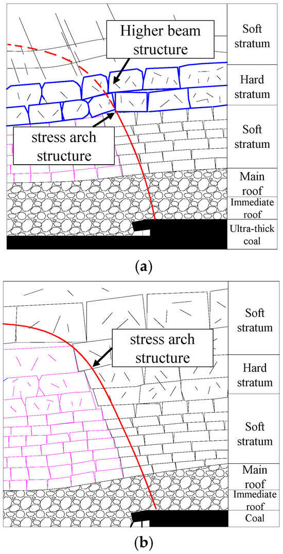
Figure 13.
Form of the bearing structure of the strata below the shell structure. (a) Higher beam structure + stress arch structure. (b) Stress arch structure.
When the degree of fragmentation of the strata near-stope is relatively high, the stress arch is essentially a stress arch AOB formed by the mutual extrusion of fractured overlying strata rocks, with the coal body in front of the working face and the peak position of abutment pressure in the goaf as the arch feet. The stress conditions of the stress arch are shown in Figure 14.
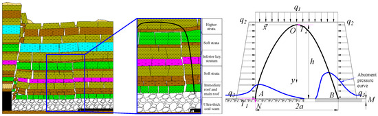
Figure 14.
Interactions between shields and surrounding rock under the roof arch bearing structure.
The pressure arch can bear compressive stress but cannot bear bending stress. The loads acting on the pressure arch include the weight q1 of the rock strata above the arch bearing structure and the lateral pressure loads q2 and q3. Taking section AO for analysis, the arch crown O is subjected to horizontal thrust T2, and the arch foot A is subjected to horizontal force T1 and support force N. The equilibrium conditions of the pressure arch are that the bending moment and shear force at any point on the arch trace AOB are zero. Combined with the model force equilibrium conditions, Formulas (4) and (5) can be obtained.
where f is the static friction coefficient of the surrounding rock, f = tan φ, and φ is the internal friction angle of the surrounding rock. By combining Formulas (4)~(6), the expression for the arch height h of the pressure arch can be obtained.
When q2 = q3 = λq1,
It can be seen from Formula (8) that with the advance of the working face, the span 2a of the pressure arch increases, the arch height h of the pressure arch increases, the original pressure arch becomes unstable, the stress in the stope is redistributed, and a new pressure arch is formed. The roof arch bearing structure continuously becomes unstable, constructs, and moves forward with the advance of the working face. According to the simulation results [26], the span of the pressure arch in slicing mining of the ultra-thick coal seam is 210 m, and the arch height of the pressure arch is 144.2 m according to Formula (8).
4. Change Characteristic of Support Load in Multi-Slice Mining of Ultra-Thick Coal Seam
Based on the evolution process and stability analysis of the roof bearing structure, the mechanical model of the relationship between the support and surrounding rock is established. The change characteristic of the hydraulic support load in ultra-thick coal seam multi-slice mining is studied by theoretical analysis and numerical simulation.
4.1. Relationship Between the Support and Surrounding Rock
The overlying strata structure in multi-slice mining of the ultra-thick coal seam undergoes an evolution process of “beam structure–higher beam structure–shell structure”. For the shell structure, there are three types of roof bearing structures above the stope: a higher beam bearing structure, higher beam bearing structure + stress arch bearing structure, and stress arch bearing structure. Therefore, this section studies the mechanical models of a stope support and surrounding rock under a beam bearing structure, higher beam bearing structure, and shell bearing arch structure, respectively.
4.1.1. Beam Bearing Structure
In the early stage of multi-slice mining of an ultra-thick coal seam, the caved rock blocks can effectively support the overlying strata, the fractured blocks of the main roof articulate with each other, and the form of the roof bearing structure is a beam structure. The relationship between the support and surrounding rock is shown in Figure 15.
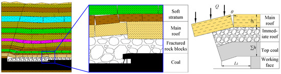
Figure 15.
Relationship between support and surrounding rock under roof beam bearing structure.
When the slice mining thickness is small, the fractured blocks of the main roof articulate to form a masonry beam structure for beam bearing. In addition to bearing the weight of the top coal and immediate roof, the hydraulic support should also meet the equilibrium conditions of the masonry beam. At this time, the load on the hydraulic support under the roof beam bearing structure is calculated by Formula (9):
where
P—support load;
∑hγ—thickness and volume force of the strata (top coal) below the main roof;
Lk—supporting distance;
θ—fracture angle of the main roof;
φ—internal friction angle of the main roof;
Q—weight of fractured blocks of the main roof and the load they bear.
When the slice mining thickness is large, according to the analysis in Section 3.1, the fractured blocks of the main roof in multi-slice mining of ultra-thick coal seams are prone to deformation and instability. At this time, based on the load transfer relationship of the main roof under limited deformation, the load on the hydraulic support is calculated by Formula (10):
where
KT—rock weight distribution coefficient, controlled by the ratio of immediate roof thickness to mining height;
Δh0—maximum roof subsidence;
Δhi—maximum allowable roof subsidence to be controlled.
4.1.2. Higher Beam Bearing Structure
In the middle stage of multi-slice mining of the ultra-thick coal seam, the articulation of fractured blocks of the main roof weakens and fails, and the fractured blocks of the upper hard strata articulate with each other to form a higher beam bearing structure. At this time, the stope roof structure consists of a cantilever beam formed by the fractured blocks with failed articulation below and a masonry beam formed by the articulated hard rock blocks above, i.e., the form of “cantilever beam + masonry beam”.
When the higher beam bearing structure is close to the stope and its articulation is stable, the roof bearing structure is formed as shown in Figure 16. The load on the support is divided into three parts: the gravity load of the top coal and immediate roof, the gravity load borne by the fractured blocks of the main roof in the form of a cantilever beam, and the rotational subsidence load of the higher beam bearing structure, which can be obtained by Formula (11).
where

Figure 16.
Relationship between support and surrounding rock under roof higher beam bearing structure (articulated stability).
hJ, γJ—thickness and volume force of the main roof and its loaded strata.
With the increase in mining times, the rotational subsidence of rock blocks in the higher beam bearing structure increases. When the higher beam bearing structure is close to the stope and its articulation is unstable, the stope roof structure is formed as shown in Figure 17.

Figure 17.
Relationship between support and surrounding rock under roof higher beam bearing structure (articulated instability).
At this time, the upper hard strata subsidence is difficult to control. The load on the hydraulic support can be obtained by Formula (12).
With the increase in slice mining times of the ultra-thick coal seam, the degree of rock block fragmentation increases, the caving zone gradually develops upward, and the higher beam bearing structure moves upward. When the ratio of the distance between the bearing structure and the coal seam to the slice mining thickness is greater than 5, the instability of the bearing structure has no clear impact on the stope support. As can be seen from Formula (12), the load on the hydraulic support at this time is the gravity load of the strata below the bearing structure, as shown in Formula (13):
where ∑hγ—thickness and volume force of the strata (top coal) below the bearing structure.
4.1.3. Shell Bearing Structure
When the overlying strata form a shell bearing structure, there are three types of stope roof bearing structures: a higher beam bearing structure, higher beam bearing structure + stress arch bearing structure, and stress arch bearing structure.
The analysis of the load on the support under the higher beam bearing structure is detailed in Section 4.1.2. When the structure is the higher beam bearing structure + stress arch bearing structure, the load on the support is the same as that under the higher beam bearing structure. However, when the articulation of the higher beam bearing structure is stable and the height of the stress arch is less than the height of the loaded strata (Figure 18b), the load on the higher beam bearing structure is the gravity load of the strata between the higher beam bearing structure and the peak of the stress arch.
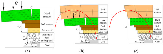
Figure 18.
Relationship between support and surrounding rock under shell bearing structure. (a) Higher beam structure. (b) Higher beam structure + stress arch structure. (c) Stress arch structure.
For the load on the hydraulic support under the stress arch bearing structure, a classification discussion should be carried out according to the positional relationship of the bearing structure: when the height of the stress arch is greater than the height of the caving zone, the maximum load on the support is the gravity load of the strata in the caving zone; when the height of the stress arch is less than the height of the caving zone, the maximum load on the support is the gravity load of the strata below the bearing structure.
4.2. Change Characteristic of Support Load
4.2.1. Theoretical Analysis of Support Load Change Characteristic
The Group B coal seam at the Dajingnan No. 1 coal mine is mined in seven slices, and the thickness of each slice is 10 m. According to Section 4.1., the stability of the beam bearing structure formed by hard rock blocks is analyzed, and the strata that can the form roof (higher) beam bearing structure in first five slices’ mining are shown in Figure 19a. The distances between the strata that can form the bearing structure and the coal seam are 9.8 m (first and second slices), 37.8 m, 95.8 m, and 106.8 m, respectively. The roof bearing structures are arch bearing structures with arch height of 144.2 m in sixth- and seventh-slice mining.
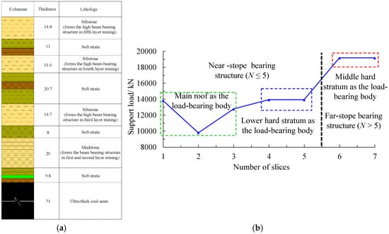
Figure 19.
Theoretical analysis of support load in ultra-thick coal seam multi-slice mining. (a) Strata that can form roof bearing structure. (b) Change curve of support load.
The roof bearing structures in the first three slices’ mining process are close to the stope, and the roof bearing structures in the last four slices’ mining process are far away from the stope. According to the analysis in Section 4.1, the maximum support load in each slice’s mining can be calculated, and a change curve of the support load is shown in Figure 19b. When the Group B coal seam at the Dajingnan No. 1 coal mine is mined in seven slices, the maximum support loads in each slice’s mining are 13,838.85 kN, 9807.10 kN, 12,763.77 kN, 13,927.39 kN, 13,927.39 kN, 19,176 kN, and 19,176 kN, respectively.
Due to the secondary fracture of the main roof blocks and the large number of near-stope hard strata, the support load under the near-stope roof bearing structure shows a change characteristic of first decreasing and then slowly increasing. Taking the support load in the first-slice mining as the benchmark, the change range of the support load is 6.40%. With the roof bearing structure away from the stope and when the amount of hard strata decreases, the support load under the far-stope roof bearing structure increases suddenly, reaching the maximum value under the arch bearing structure. At this time, the support load is 19,176 kN, an increase of 38.57% compared with the first slice.
4.2.2. Numerical Simulation of Support Load Change Characteristic
GPU Continuum-based Discrete Element Method software (GDEM, GDEM Technology Beijing Co., Ltd., Beijing, China) is used to conduct a numerical simulation study on the change characteristic of the support load in multi-slice mining of the Group B coal seam. The model size is 500 m (length) by 390 m (height), and the vertical direction is from the coal floor to the surface. The side and bottom boundary displacement are constrained, and the upper boundary represents the free surface. The total thickness of the coal seam is 70 m, divided into seven mining layers. A total of 400 m of each slice is extracted, and there is a 50 m wide barrier pillar left to minimize the boundary effects. Top caving coal mining is adopted with a mining height of 5 m and caving heights of 5 m, 10 m, and 15 m. This section does not consider the control effect of hydraulic supports on the roof; thus, no parameters are assigned to the hydraulic supports. The hydraulic supports are regarded as rigid bodies, and the vertical stresses in the top coal and immediate roof are monitored. The weighted average of the vertical stresses in each mining stage is taken as the pressure on the roof. The numerical simulation model is shown in Figure 20.

Figure 20.
Numerical simulation model.
Taking the multi-slice mining thickness of 10 m as an example, the articulation situation of fractured hard stratum blocks in the process of multi-slice mining is shown in Figure 21. The numerical simulation result of the roof bearing structure evolution process is aligned with the theoretical analysis conclusion. The roof bearing structure is a beam bearing structure in the first two slices’ mining, a higher beam bearing structure from the third to the fifth slices, and an arch bearing structure in sixth- and seventh-slice mining. There is no change in the rock strata that bear the load.

Figure 21.
Articulation situation of fractured hard strata blocks in the process of multi-slice mining. (a) First-slice mining, beam bearing structure. (b) Second-slice mining, beam bearing structure. (c) Third-slice mining, higher beam bearing structure. (d) Fourth-slice mining, higher beam bearing structure. (e) Fifth-slice mining, higher beam bearing structure. (f) Sixth-slice mining, arch bearing structure. (g) Seventh-slice mining, arch bearing structure.
The change curve of the hydraulic support load in ultra-thick coal seam multi-slice mining is shown in Figure 22.

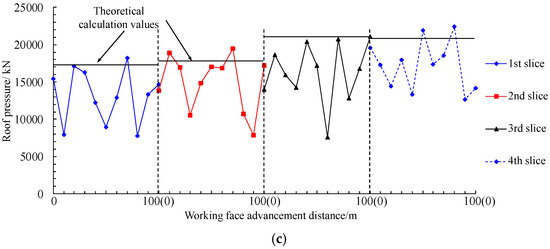
Figure 22.
Load change curve of hydraulic support in ultra-thick coal seam multi-slice mining. (a) Slicing thickness of 10 m. (b) Slicing thickness of 15 m. (c) Slicing thickness of 20 m.
According to the numerical simulation results, when the multi-slice mining thickness of ultra-thick coal seams is 10 m, the maximum loads on the hydraulic support of each slice during the multi-slice mining are 16,086.42 kN, 14,233.52 kN, 15,776.25 kN, 15,891.52 kN, 15,470.26 kN, 19,244.79 kN, and 20,372.67 kN, respectively. Taking the support load during the first-slice mining as the benchmark, the maximum increase amplitude is 26.64%. When the multi-slice mining thickness is 15 m, the maximum loads on the hydraulic support of each slice are 17,194.45 kN, 16,963.62 kN, 15,656.83 kN, 19,464.66 kN, and 21,385.23 kN, respectively, with a maximum increase amplitude of 24.37% compared with the first slice. When the multi-slice mining thickness is 20 m, the maximum loads on the hydraulic support of each slice are 18,182.82 kN, 19,494.89 kN, 21,064.53 kN, and 22,435.00 kN, respectively, with a maximum increase amplitude of 23.39% compared with the first slice.
The overall variation amplitude of the hydraulic support load is consistent with the theoretical calculation results. The variation amplitude of the roof pressure under the far-stope roof bearing structure is small, and the roof pressure shows the variation characteristics of “slow increase under the near-stope roof bearing structure and stabilization under the far-stope roof bearing structure”.
5. Control of Strata Behavior in Multi-Slice Mining of Ultra-Thick Coal Seam
5.1. Control Mechanism of Stope Strata
The source of the support load can divide into two parts: the gravity load of rock blocks under the roof bearing structure, and the load caused by rotary subsidence of the bearing structural blocks. Thus, the control of the support load should be considered from the two aspects of controlling the development height of the bearing structure and reducing the rotary subsidence load of the bearing structure.
5.1.1. Control Mechanism of Stope Strata Under the Near-Stope Roof Bearing Structure
At the early stage of mining, controlling the development height of the bearing structure serves to ensure the stability of the near-stope roof bearing structure. With the increase in slicing mining thickness and mining times, the residual crushing expansion of the caved blocks and the filling degree of the goaf decrease gradually. The rotary subsidence amount of the blocks in a hard stratum increases, and the (higher) beam bearing structure is prone to rotary deformation instability. Therefore, improving the filling degree of the goaf by grouting into the goaf can be adopted to ensure the stability of the near-stope roof bearing structure.
The overburden of the ultra-thick coal seam in Xinjiang is sedimentary rock with an average thickness of 20~30 m. The periodic breakage length of the main roof is large, which is due to the large rotary subsidence load. According to the change characteristic of the support load, on the premise of ensuring the stability of the bearing structure, the support load can be significantly reduced by reducing the breakage length of the main roof through pre-splitting.
5.1.2. Control Mechanism of Stope Strata Under the Far-Stope Roof Bearing Structure
At the later stage of mining, as discussed earlier, the stress on the support is mainly from the gravity load of loose blocks in the arch. According to Formula (8), the height of roof arch bearing structure H is reduced by increasing the static friction coefficient of the surrounding rock in goaf f. And the static friction coefficient is related to the condition of support, the integrity of top coal, and the compaction degree of blocks in the goaf. Grouting into the goaf and reducing the top coal recovery rate can promote the compaction degree of blocks in the goaf, control the development height of the roof arch bearing structure, and reduce the range of strata controlled by the support.
During the advancing process of the working face, the strata above the stope are unstable from bottom to top. When the unstable rock strata develop to the critical height of the pressure arch, the upper rock blocks are compressed together to form an arch bearing structure, and the strata are no longer unstable upward. The advancing speed of the working face can be increased, so that the mining can be completed before the height of the pressure arch above the stope reaches the critical height, and the range of strata controlled by the support reduces. The load on support decreases.
5.2. Control Countermeasures of Stope Strata
According to the above analysis, the technical measures for controlling the stability of the roof are put forward.
- (1)
- Grouting into goaf
During the whole process of ultra-thick coal seam multi-slice mining, grouting into the goaf can improve the filling degree and block the compaction degree of the goaf, which can control the development height of the roof bearing structure and reduce the range of strata controlled by the support. Under the near-stope roof bearing structure, grouting can increase the filling degree of the goaf, reduce the rotary subsidence amount of the blocks, and improve the stability of the near-stope roof bearing structure. Under the far-stope roof bearing structure, grouting can effectively improve the internal friction angle and the static friction coefficient of the rock blocks in the goaf, and it can control the development height of the roof arch bearing structure.
- (2)
- Pre-splitting thick and hard roof in first-slice mining
In the first-slice mining process, the breakage length of the main roof is reduced by drilling pre-splitting, which reduces the rotary subsidence load on the support. Taking multi-slice mining of the Group B coal seam at the Dajingnan No. 1 mine as an example, the main roof is pre-cracked by drilling in the first-slice mining process, as shown in Figure 23. The slicing thickness is 10 m.

Figure 23.
Pre-splitting thick and hard roof in first-slice mining. (a) Before the roof drilling pre-splitting. (b) After the roof drilling pre-splitting.
Before the roof drilling pre-splitting, the load on the hydraulic support is the rotary subsidence load caused by the broken main roof blocks A and B and the gravity load of the rock blocks in the range of ∑h1. The value of the support load is 13,741.96 kN. After the roof drilling pre-splitting, the breakage length of the main roof is reduced from 23 m to 12 m, and the load on the hydraulic support is the rotary subsidence load caused by the broken main roof block A and the gravity load of the rock blocks in the range of ∑h2. The value of the support load is 8559.56 kN, which is 37.71% less than the support load before drilling pre-splitting. The voussoir beam structure can still be formed by the broken main roof blocks in the second-slice mining, and the near-stope roof bearing structure is stable.
- (3)
- Reducing the working face length in the late stage of mining
For the ultra-thick coal seam, when the multi-slice mining thickness is 15 m, reducing the working face length from 220 m to 120~150 m for short working face mining can not only ensure the caving property of the top coal but also have an clear effect in controlling the stope ground pressure.
Taking the multi-slice mining of Group B coal in the No. 7 Minefield of the Dajing Mining Area with a multi-slice mining thickness of 15 m as an example, when the working face length is 220 m, during the fifth-slice mining, the main key layer of the overlying strata articulates to form a shell structure, and the stope support bears the gravity load of the strata below the middle hard strata, which is 20,065.24 kN. When the working face length of the fifth slice is 120 m, according to the content in Section 3.2, the internal friction angle of the overlying strata is 30°, the span of the stress arch is 120 m, and the corresponding height of the stress arch is 51.99 m. At this time, the load on the support is 1449.75 kPa, and the pressure is 14,787.45 kN, a decrease of 26.31%.
From the perspective of maximum economic benefit, the maximum load on the roof of the first four slices when the multi-slice mining thickness is 15 m does not exceed 18,000 kN, corresponding to the gravity load of the 10 m top coal and 64.59 m overlying strata. That is, if the maximum supporting capacity of the hydraulic support during the fifth-slice mining is 18,000 kN, the allowable maximum working face width is 149.07 m. Therefore, the working face length of the first four slices in the multi-slice mining of ultra-thick coal seams can be 220 m, and the working face length of the fifth slice can be 140 m.
- (4)
- Reducing the top coal recovery rate and increasing the advance speed of working face at the later stage of mining
At the later stage of mining, the roof bearing structure is far away from the stope. By reducing the top coal recovery rate and increasing the advance speed of the working face, the filling degree of the goaf can be improved, and the range of unstable rock strata above the stope can be effectively controlled. The gravity load on the hydraulic support can be reduced. The simulation scheme is the same as in Section 4.2. By reducing the number of calculation steps to simulate the rapid advancement of the working surface (the number of calculation steps is reduced by half), the change curve of the support load is obtained, as shown in Figure 24.

Figure 24.
Change curve of support at different working face advancing speed.
When the working face is advancing at a normal speed, the maximum loads of the hydraulic support during the fifth to seventh-slice mining process are 23,709.37 kN, 30,176.85 kN, and 28,464.17 kN, respectively, and the average loads of the hydraulic support are 18,143.79 kN, 22,997.11 kN, and 20,582.47 kN, respectively. When the working face is advancing rapidly, the maximum loads on the hydraulic support are 23,156.23 kN, 28,209.12 kN, and 26,325.96 kN, reducing by 2.33%, 6.52%, and 7.51%, respectively. And the average loads are 14,833.91 kN, 20,639.14 kN, and 19,055.12 kN, reducing by 18.24%, 10.25%, and 7.42%, respectively.
6. Conclusions
Based on the occurrence conditions of a typical ultra-thick coal seam in the East Junggar coalfield, this study adopts physical simulation, theoretical calculation, and numerical analysis methods to conduct systematic research on the stability mechanism of roof bearing structures, characteristics of ground pressure behavior, and corresponding control technical measures under the conditions of a large-scale mining volume and multi-mining disturbances in multi-slice mining of the ultra-thick coal seam. The main conclusions are as follows:
- (1)
- This study reveals the evolution process of the overlying strata structure in multi-slice mining of the ultra-thick coal seam, which follows the sequence of “beam structure–higher beam structure–shell structure”. It also illustrates the fracture and articulation characteristics of the overlying strata in multi-slice mining of the 70 m ultra-thick coal seam in East Junggar: in the early stage, fractured rock blocks of the lower hard strata form beam-type articulation; in the middle stage, the lower articulation structure weakens and fails, and the beam-type articulation structure moves upward in a stepped manner; in the late stage, the mined-out space continues to expand, and the far-stope strata undergo transverse O-X fracture, with the fractured rock blocks squeezing to form a shell. The corresponding forms of roof bearing structures are clarified, and the delamination fracture and movement mechanism of load-bearing strata as well as the stability conditions of arch bearing structures are analyzed.
- (2)
- Mechanical models of the support–surrounding rock relationship under different overlying strata structures are established. The range of strata to be controlled by the support in different mining stages of the ultra-thick coal seam is defined, and the corresponding calculation method for the support load is proposed. It reveals the ground pressure behavior characteristics of multi-slice mining of the ultra-thick coal seam: “under the near-stope roof bearing structure, the load first decreases and then increases slowly; under the far-stope roof bearing structure, the load increases abruptly and then tends to be stable”. During the multi-slice mining of the ultra-thick coal seam, due to the large number of near-stope hard strata, the load on the hydraulic support under the near-stope roof bearing structure is small and increases slowly. As the roof bearing structure moves away from the stope and the number of hard strata decreases, the load on the hydraulic support under the far-stope roof bearing structure increases abruptly. When the slicing mining thicknesses are 10 m, 15 m, and 20 m, the increase amplitudes of the support load are 26.64%, 24.37%, and 23.39%, respectively.
- (3)
- Starting from the control idea of “ensuring the stability of the near-stope roof bearing structure and reducing the rotational subsidence of fractured rock blocks of hard strata”, control technical measures for the 70 m ultra-thick coal seam in East Junggar are proposed: in the early mining stage, “pre-splitting of the main roof and strata on the open-off cut side during the first-slice mining”; in the late mining stage, “short working face mining + reducing slicing mining thickness + rapid advancement”; during the entire mining process, “grouting in goafs and bed separation zones”. By implementing roof drilling pre-splitting and rapid working face advancement, it is expected that the maximum load on the support can be reduced by 37.71% and 2.33~7.51%, respectively. In the late mining stage, with short working face mining, the maximum load on the support is reduced from 20,017.5 kN to 16,192.5 kN, which is conducive to the lightweight selection of supports.
Author Contributions
Conceptualization, C.Y. and D.Q.; methodology, C.Y.; software, D.Q.; validation, X.W. and X.C.; formal analysis, X.C.; investigation, C.Y.; resources, C.Y.; data curation, X.W.; writing—original draft preparation, D.Q.; writing—review and editing, C.Y. and X.W.; visualization, X.C.; supervision, C.Y.; project administration, C.Y.; funding acquisition, C.Y. All authors have read and agreed to the published version of the manuscript.
Funding
This research was funded by the National Natural Science Foundation of China (Grant No. 52104140), the Fundamental Research Funds for the Central Universities (2025QN1002), and Dananhu No. 1 Mine (No. 2023-57).
Data Availability Statement
The data will be made available on request.
Acknowledgments
The authors thank the Zhundong No. 2 Mine of CHN ENERGY for providing the technical support.
Conflicts of Interest
Author Changmo Yuan was employed by the company State Grid Energy Hami Coal Power Co., Ltd. The remaining authors declare that the research was conducted in the absence of any commercial or financial relationships that could be construed as a potential conflict of interest.
References
- Khan, I.; Javed, A. Spatio-temporal land cover dynamics in open cast coal mine area of Singrauli, MP, India. J. Geogr. Inf. Syst. 2012, 4, 521–529. [Google Scholar]
- Chen, L.; Zhang, D.S.; Fan, G.W.; Zhang, S.Z.; Wang, X.F.; Zhang, W. A new repeated mining method with preexisting damage zones dilled for ultra-thick coal seam extraction–case study. Front. Earth Sci. 2022, 10, 835867. [Google Scholar]
- Rošer, J.; Potočnik, D.; Vulić, M. Analysis of dynamic surface subsidence at the underground coal mining site in Velenje, Slovenia through modified sigmoidal function. Minerals 2018, 8, 74. [Google Scholar] [CrossRef]
- Zhou, Y.Z.; Zhang, D.S.; Fan, G.W.; Zhang, S.; Zhang, S.Z. Feasibility study on fully mechanized large mining height long wall top-coal caving mining in ultra-thick (20–30 m), parting-rich coal seams: A case study of the laosangou mining field in China. Energy Sources Part A Recovery Util. Environ. Eff. 2025, 47, 2165–2188. [Google Scholar] [CrossRef]
- Feng, J.W.; Wang, W.M.; Wang, Z.; Lou, F.; Wang, H.Z.; Wu, R.; Jia, Y.Y.; Yong, M.C. Study on the mechanism and control of strong rock pressure in thick coal seam mining under the goaf of very close multiple coal seams. Processes 2023, 11, 1320. [Google Scholar] [CrossRef]
- Likar, J.; Medved, M.; Lenart, M.; Mayer, J.; Malenković, V.; Jeromel, G.; Dervarič, E. Analysis of geomechanical changes in hanging wall caused by longwall multi top caving in coal mining. J. Min. Sci. 2012, 48, 135–145. [Google Scholar] [CrossRef]
- Jeromel, G.; Medved, M.; Likar, J. An analysis of the geomechanical processes in coal mining using the Velenje mining method. Acta Geotech. Slov. 2010, 7, 30–45. [Google Scholar]
- Chen, H.D.; Chen, X.J.; Li, J.W.; Wang, L. Stress evolution characteristics of lower slice coal body during mining the thick coal seam. Geotech. Geol. Eng. 2018, 36, 3223–3234. [Google Scholar] [CrossRef]
- Kang, Y.H.; Huang, F.C.; Xi, J.D. Overburden failure law of fully mechanized repeated mining. Coal Sci. Technol. 2001, 29, 22–24. (In Chinese) [Google Scholar]
- Wang, X.L.; Qin, Q.R.; Fan, C.H. Failure characteristic and fracture evolution law of overburden of thick coal in fully mechanized sub-level caving mining. Sains Malays. 2017, 46, 2041–2048. [Google Scholar] [CrossRef]
- Ning, J.G.; Wang, J.; Tan, Y.L.; Xu, Q. Mechanical mechanism of overlying strata breaking and development of fractured zone during close-distance coal seam group mining. Int. J. Min. Sci. Technol. 2020, 30, 207–215. [Google Scholar] [CrossRef]
- Yang, X.L.; Wen, G.C.; Dai, L.C.; Sun, H.T.; Li, X.L. Ground subsidence and surface cracks evolution from shallow-buried close-distance multi-seam mining: A case study in Bulianta coal mine. Rock Mech. Rock Eng. 2019, 52, 2835–2852. [Google Scholar] [CrossRef]
- He, C.C.; Xu, J.L. Subsidence prediction of overburden strata and surface based on the voussoir beam structure theory. Adv. Civ. Eng. 2018, 2018, 1–13. [Google Scholar] [CrossRef]
- Lan, Y.W.; Gao, R.; Yu, B.; Meng, X.B. In situ studies on the characteristics of strata structures and behaviors in mining of a thick coal seam with hard roofs. Energies 2018, 11, 2470. [Google Scholar] [CrossRef]
- Shi, J.L.; Yan, S.H.; Xu, Z.H.; Xue, J.S.; Zhao, K.K.; Zheng, J.W. Analysis of the progressively enhanced mine pressure in the fully mechanized top coal caving work face of a 20 m ultra-thick coal seam. Shock Vib. 2021, 2021, 6678207. [Google Scholar]
- Lv, H.Y.; Cheng, Z.B.; Liu, F.; Wei, W.J. Stress, displacement, and crack evolution of top-coal layers in high-intensity repeated mining with extra-thick coal seam. Comput. Part. Mech. 2025, 12, 2879–2893. [Google Scholar] [CrossRef]
- Majid, K.; He, X.Q.; Song, D.Z.; Tian, X.H.; Li, Z.L.; Xue, Y.R.; Khurram, S.A. Extracting and predicting rock mechanical behavior based on microseismic spatio-temporal response in an ultra-thick coal seam mine. Rock Mech. Rock Eng. 2023, 56, 3725–3754. [Google Scholar]
- Liang, S.; Zhang, X.P.; Ke, F.H.; Liu, J.H.; Yao, Q.L.; Luo, H.Y.; Li, X.H.; Xu, Y.N. Evolution of overlying strata bed separation and water inrush hazard assessment in fully mechanized longwall top-coal caving of an ultra-thick coal seam. Water 2025, 17, 850. [Google Scholar] [CrossRef]
- Wang, F.; Xu, J.L.; Xie, J.L. Effects of arch structure in unconsolidated layers on fracture and failure of overlying strata. Int. J. Rock Mech. Min. Sci. 2019, 114, 141–152. [Google Scholar] [CrossRef]
- Yu, B. Behaviors of overlying strata in extra-thick coal seams using top-coal caving method. J. Rock Mech. Geotech. Eng. 2016, 8, 238–247. [Google Scholar] [CrossRef]
- Yu, B.; Zhao, J.; Kuang, T.J.; Meng, X.B. In situ investigations into overburden failures of a super-thick coal seam for longwall top coal caving. Int. J. Rock Mech. Min. Sci. 2015, 78, 155–162. [Google Scholar] [CrossRef]
- Yu, B.; Zhu, W.B.; Li, Z.; Gao, R.; Liu, J.R. Mechanism of the instability of strata structure in far field for super-thick coal seam mining. J. China Coal Soc. 2018, 43, 2398–2407. [Google Scholar]
- Wang, W.; Cheng, Y.P.; Wang, H.F.; Liu, H.Y.; Wang, L.; Li, W.; Jiang, J.Y. Fracture failure analysis of hard–thick sandstone roof and its controlling effect on gas emission in underground ultra-thick coal extraction. Eng. Fail. Anal. 2015, 54, 150–162. [Google Scholar] [CrossRef]
- Deng, X.J.; Zhang, J.X.; Kang, T.; Han, X.L. Strata behavior in extra-thick coal seam mining with upward slicing backfilling technology. Int. J. Min. Sci. Technol. 2016, 26, 587–592. [Google Scholar] [CrossRef]
- Lin, N.; Sasaoka, T.; Shimada, H.; Matsui, K. Numerical study on an applicable underground mining method for soft extra-thick coal seams in Thailand. Engineering 2012, 4, 739–745. [Google Scholar] [CrossRef]
- Wang, X.F.; Qin, D.D.; Zhang, D.S.; Guan, W.M.; Xu, M.T.; Wang, X.L.; Zhang, C.G. Evolution characteristics of overburden strata structure for ultra-thick coal seam multi-layer mining in Xinjiang East Junggar Basin. Energies 2019, 12, 332. [Google Scholar] [CrossRef]


Disclaimer/Publisher’s Note: The statements, opinions and data contained in all publications are solely those of the individual author(s) and contributor(s) and not of MDPI and/or the editor(s). MDPI and/or the editor(s) disclaim responsibility for any injury to people or property resulting from any ideas, methods, instructions or products referred to in the content. |
© 2025 by the authors. Licensee MDPI, Basel, Switzerland. This article is an open access article distributed under the terms and conditions of the Creative Commons Attribution (CC BY) license (https://creativecommons.org/licenses/by/4.0/).