1. Introduction
As a natural geological material, rocks are characterized by the presence of a wide range of scale-different, shape-varied, and randomly distributed fissure networks within their interiors [
1,
2]. These initial defects are the core factors that control the mechanical properties of rocks, especially their critical weakness in tensile strength [
3,
4,
5,
6,
7]. In many rock mass engineering practices such as mining, tunnel excavation, slope stability, and underground reservoir construction, brittle fracture dominated by tensile stress is one of the main modes that induce rock mass instability and even catastrophic failure [
8,
9,
10]. Yellow sandstone, a widely distributed typical sedimentary rock, often constitutes the surrounding rock medium of major projects. The randomly existing natural fissures within it significantly weaken the integrity and load-bearing capacity of the rock mass, making the accurate prediction of its tensile mechanical response and fracture evolution process a key challenge for engineering safety.
To explore the influence of fissures on the macroscopic and microscopic mechanical properties and failure characteristics of rocks, experts and scholars from both domestic and international fields have conducted extensive laboratory experiments in recent years [
11,
12]. Yang et al. [
13] carried out the uniaxial compression test on granite specimens with a single fissure to study the effects of fissure angle and heat treatment temperature on the mechanical properties and deformation failure behavior. Han et al. [
14] developed a numerical model based on the FEM-CZM method to explore the shear behavior of rock-like materials with fissure holes. Yang et al. [
15] conducted a series of experiments on 70 non-persistent jointed rock specimens to investigate the effects of anchorage method on the strength and deformation behavior of rock specimens. Wang et al. [
16] conducted the cyclic uniaxial increasing-amplitude decreasing-frequency loads on granite specimens containing a circular hole and two fissures with different rock bridge lengths. Li et al. [
17] carried out uniaxial compression experiments on specimens containing combined hole–joint flaw assisted by acoustic emission and digital image correlation technologies. Huang et al. [
18] conducted a series of experiments to quantitatively evaluate the fracture surface morphology of marble specimens with different fissure network angles.
To further explore the microscopic mechanisms such as stress redistribution, crack initiation competition, and interaction between crack propagation paths in fissured rock masses under external loads, experts and scholars have conducted a large number of numerical simulation studies using methods such as finite element and discrete element approaches in recent years [
19,
20,
21,
22]. Yu et al. [
23] improved the existing smooth kernel function and proposed a rock damage meshless numerical simulation method, which reproduced the crack propagation process of rocks under different fissure opening degrees. Yang et al. [
24] established a peridynamics model of sandstone with two fissures under conventional triaxial compression conditions to simulate the mechanical behavior and crack evolution characteristics of the sandstone specimens. Diao et al. [
25] used PFC2D 6.0 software to study the local displacement field, force field distribution, and crack evolution characteristics of fissured rock under different rock bridge inclinations. Liu et al. [
26] employed the finite–discrete element method to examine the mechanism through which fissure water pressure affects the initiation and propagation of cracks in the rock.
Currently, it is difficult to precisely control the spatial variability of fracture parameters in physical experiments, and conventional numerical models often simplify fractures as regularly distributed, meaning they are unable to truly reflect the fracture characteristics of natural rock masses [
27]. In recent years, the development of random fissure modeling and micro–macro damage mechanics methods has provided new ideas for solving these problems. Scholars have explored the failure mechanism of fissured rock masses through methods such as FDEM and PFC, but there is still a lack of research on the tensile behavior under the coupling effect of differential mineral component assignment and random fissure spatial statistical distribution. Especially in sandstone with multiple mineral components, the interaction mechanism between fissure geometric parameters (inclination angle and density) and the spatial distribution of minerals on the influence of crack propagation path is still unclear.
Therefore, this paper takes sandstone with randomly distributed fissures as the research object and combines Brazilian splitting tests and numerical simulation methods as follows: based on Python 3.13, the secondary development of ABAQUS is carried out, and the Monte-Carlo method is used to generate a random fissure network that conforms to statistical laws; based on the XRD mineral composition analysis results, the physical and mechanical parameters of the grid are differentiated and assigned, and cohesive elements are inserted to characterize crack evolution; through systematic parameter variations (five types of fissure inclination angles θ × five types of fissure ratios R), the control mechanism of θ and R on the attenuation law of tensile strength, the transformation of failure mode, and the control mechanism of crack propagation path is revealed; and combined with macro–micro failure characteristics (proportion of crack types, evolution of stress field, etc.), the competitive conversion conditions of tensile–shear failure are clarified. The research results will provide theoretical support for the modeling of fissure rock mass damage and the prevention and control of engineering disasters.
2. Construction of Numerical Simulation Models
2.1. The Numerical Modeling Process
A numerical model for the Brazilian splitting test of sandy limestone with randomly distributed fissures was constructed using the ABAQUS 2020 numerical simulation software, as shown in
Figure 1. The specific process is as follows:
(1) The numerical model adopts a two-dimensional model. Firstly, a circular disk with a diameter of 50 mm and a thickness of 1 mm is generated to construct the Brazilian disk component of the yellow sandstone.
(2) Using Python to write programs for the secondary development of the ABAQUS software, random fracture parameters and geometries are generated based on the Monte-Carlo principle. Under the same working condition, the fracture size is fixed (length × width = 5 mm × 0.5 mm), the fracture inclination remains unchanged, and there is no overlap between fractures. The centroids of the fractures follow the Weibull distribution to generate random fractures.
(3) The grid was divided using the four-node bilinear planar strain quadrilateral element (CPE4R). Considering the computational efficiency and accuracy of the model, the grid size was uniformly set to 0.5 mm.
(4) The mineral composition and proportions of the yellow sandstone were determined using an X-ray diffractometer. Based on the proportions of different minerals, grids were randomly extracted for distribution and assigned different physical and mechanical parameters.
(5) Zero-thickness cohesive elements are inserted between the solid element grids. The initiation and propagation process of cracks in the specimen under external loads is reproduced based on the damage and failure of the cohesive elements. The damage evolution of the cohesive elements follows the maximum principal stress criterion, and the cross-sectional properties satisfy the traction–separation response.
2.2. Parameter Calibration and Simulation Plan
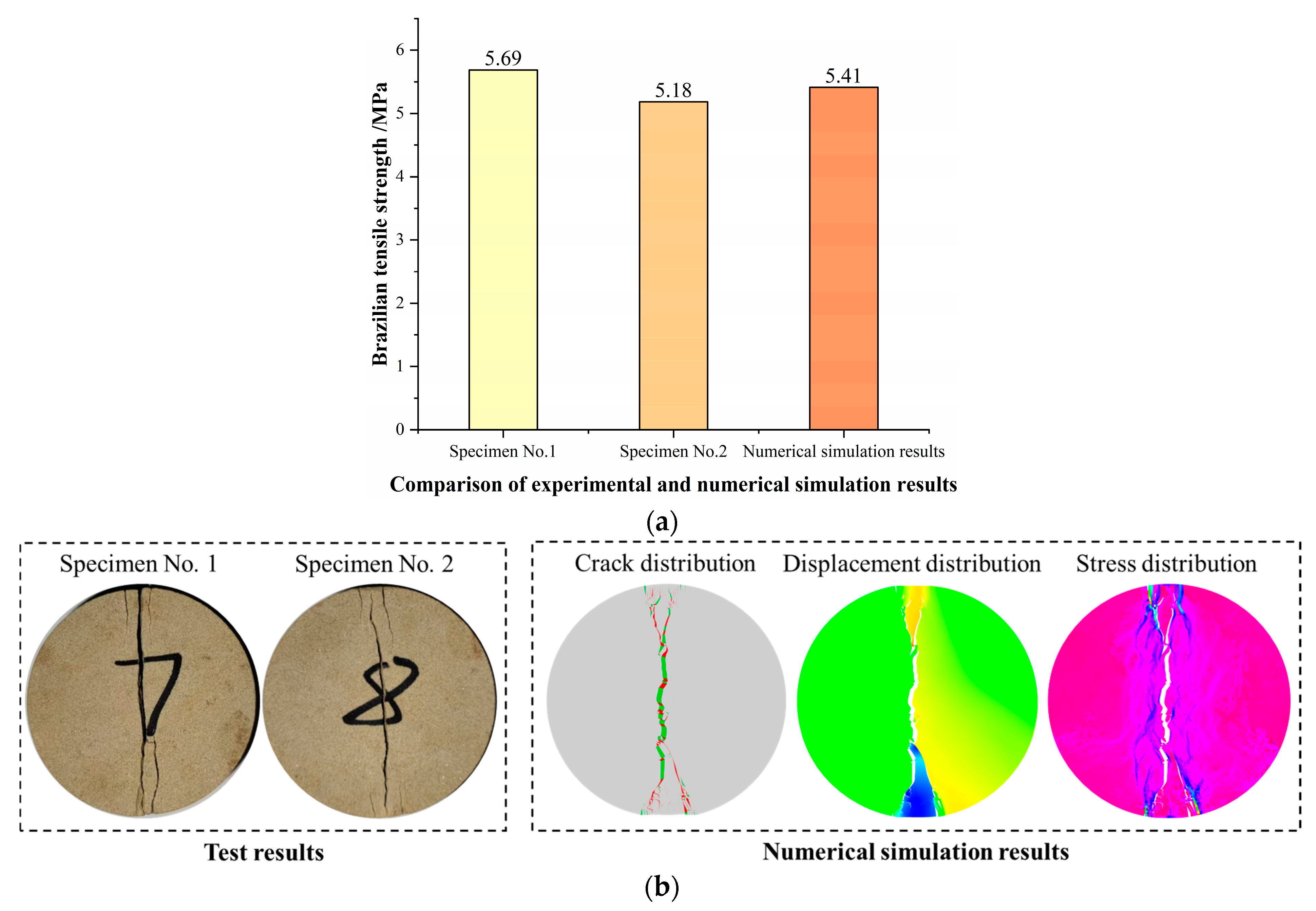
A sample of yellow sandstone collected from the site is selected to prepare 50 × 25 mm Brazilian disk specimens. Then, the Brazilian splitting test is conducted on the yellow sandstone specimens to obtain the tensile strength and failure mode of the specimens, which will be used for parameter calibration in numerical simulation (as shown in
Figure 2). The Brazilian splitting test is carried out on the numerical model constructed in
Section 2.1, with rigid plates set at the upper and lower ends of the specimen. During the test, the bottom plate is fixed, and the top plate moves downward at a fixed rate (0.05 mm/min), with the loading rate being the same as the test (0.05 mm/min). The physical and mechanical parameters of different minerals are mainly determined through nanoindentation technology, as shown in
Table 1. The parameters of the cohesive elements are determined by the “trial-and-error method”, that is, by continuously adjusting the parameters of the cohesive elements until the tensile strength of the numerical simulation specimen is close to the test result and the failure mode is the same as the test result, as shown in
Figure 2. The physical and mechanical parameters of the cohesive elements are shown in
Table 2.
The numerical simulation scheme sets the inclination angle of the fissures to five values, namely θ = 0°, 22.5°, 45°, 67.5°, and 90°, and the fracture ratio to five values, namely R = 3%, 6%, 9%, 12%, and 15%. In total, there are 25 numerical models. After the numerical calculation, the tensile strength, failure mode, and crack propagation characteristics of the fissured yellow sandstone are analyzed to reveal the mechanism of the influence of fissure inclination angle and fissure ratio on the tensile mechanical behavior of the yellow sandstone.
3. Result Analysis
3.1. Change in Brazilian Tensile Strength
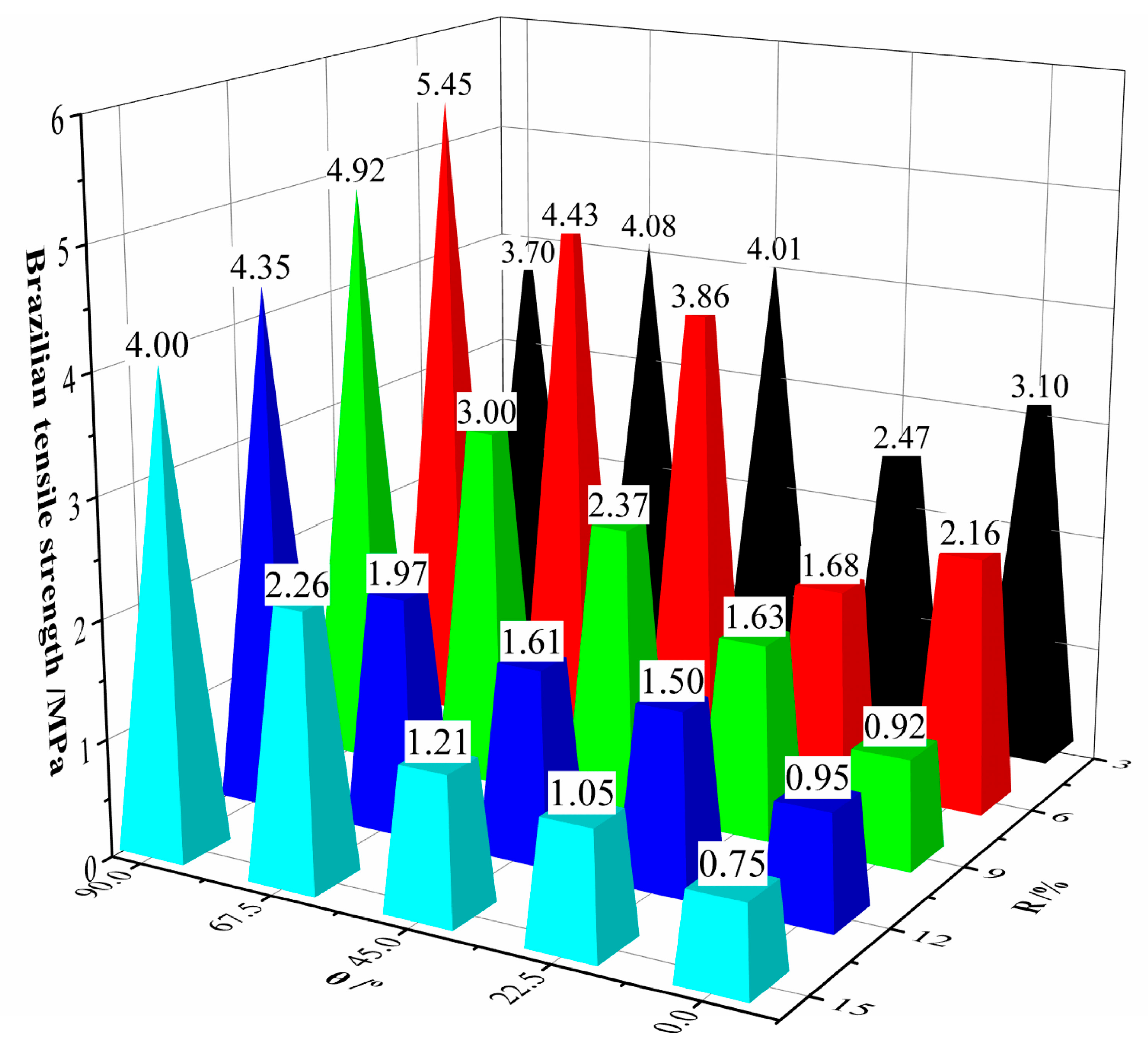
Figure 3 shows the Brazilian tensile strength of the yellow sandstone under different fissure ratios and fissure inclination angles. As the fissure ratio increases, the Brazilian tensile strength of the yellow sandstone specimens generally decreases (except when θ = 67.5° and 90°, where R increases from 3% to 6%). The main reason is that the increase in fissure ratio leads to an increasing number of fissures within the specimen and an increase in the number of defects within the specimen, resulting in a continuous weakening of the resistance of the yellow sandstone specimens to external loads.
The Brazilian tensile strength of the yellow sandstone specimens shows three typical patterns of change with the increase in the fissure inclination angle: when R = 3%, the Brazilian tensile strength first decreases, then increases, and finally decreases again; when θ = 67.5° and 22.5°, the maximum and minimum values are achieved, respectively; when R = 6%, the Brazilian tensile strength first decreases and then increases, with the critical inclination angle θ being 22.5°; and when R = 9%, 12%, and 15%, the Brazilian tensile strength continuously increases. The differences in the variation trend of yellow sandstone’s Brazilian tensile strength under different fissure ratios with the increase in the fissure inclination angle are likely related to the competitive interaction between the orientation of fissures relative to the maximum tensile stress trajectory and the local stress shadows or amplifications caused by fissure interactions.
3.2. Macroscopic and Microscopic Failure Characteristics
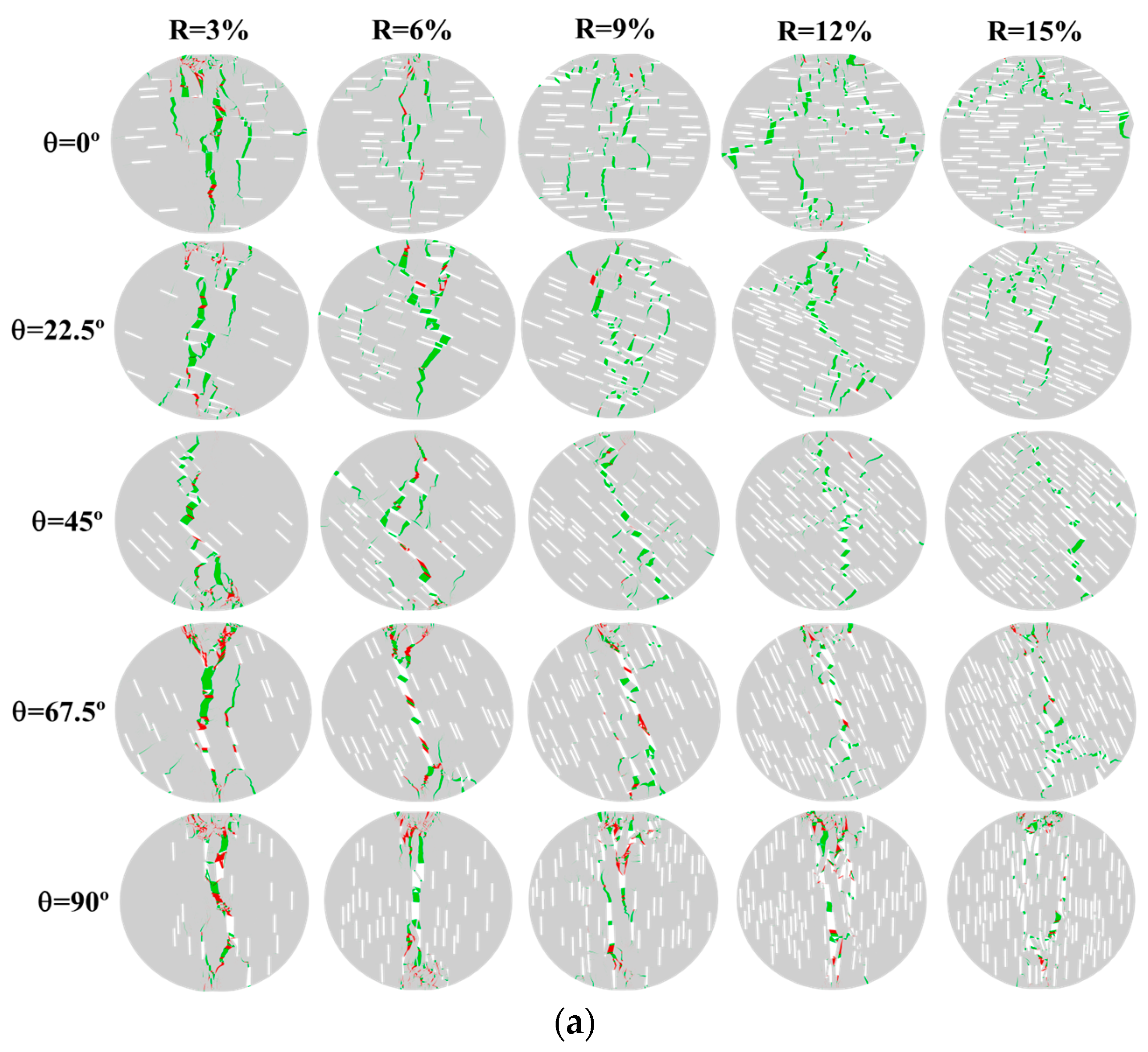
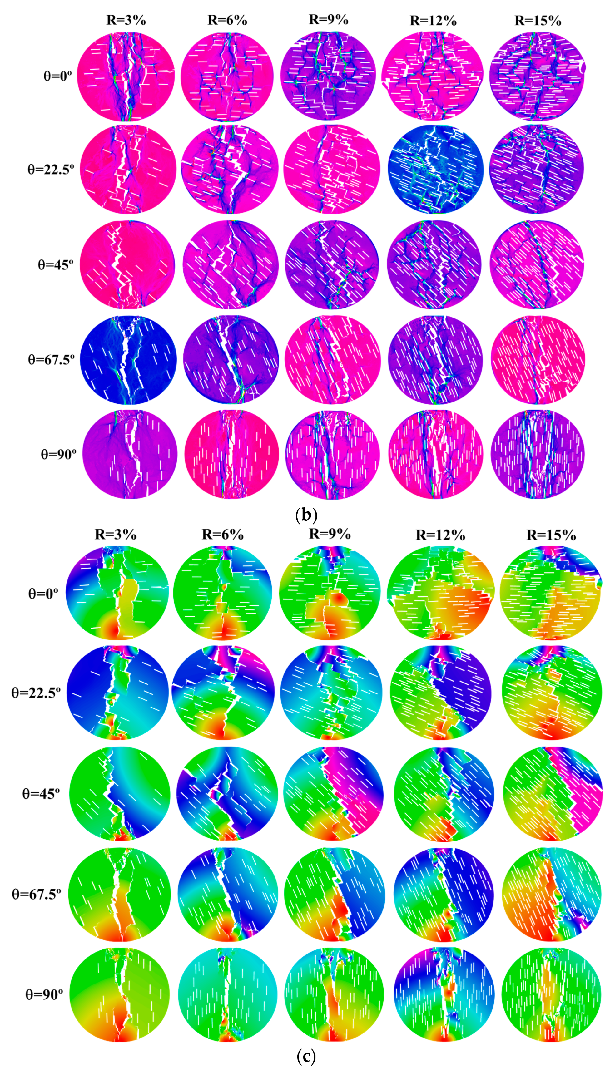
Figure 4 shows the failure modes of the yellow sandstone specimens under different fissure ratios and fissure inclination angles.
Figure 4a–c represent the crack field, principal stress field, and displacement field when the specimen failed. In
Figure 4a, the green color represents tensile cracks, and the red color represents shear cracks. As can be seen from the figure:
(1) The fissure ratio has a significant impact on the failure mode of the specimens. When the fissure inclination angle is between 0° and 67.5°, the main crack of the specimen undergoes central failure along the vertical loading direction when the fissure ratio is low. As the fissure ratio increases, the main crack of the specimen continuously deviates from the vertical loading direction, and the degree of deviation increases with the increase in fissure ratio. This is mainly due to the fact that the initial existing cracks have a guiding effect on the expansion of the main crack. As the fissure ratio increases, the number of cracks within the specimen continuously increases, and during the loading process, the main crack is more likely to expand towards the initial existing cracks, thereby causing the main crack of the specimen to continuously shift. When θ = 90°, the main crack of the specimen deviates slightly along the vertical loading direction, but the overall deviation degree is relatively small. In this case, the cracks are closely related to the vertical direction.
(2) The failure morphology of the specimens shows two typical trends as the fissure inclination angle increases: when R is between 3% and 9%, the deviation degree of the main failure crack of the specimens along the vertical loading direction first increases and then decreases, while when R is 12% and 15%, the deviation degree of the main failure crack of the specimens along the vertical loading direction keeps decreasing.
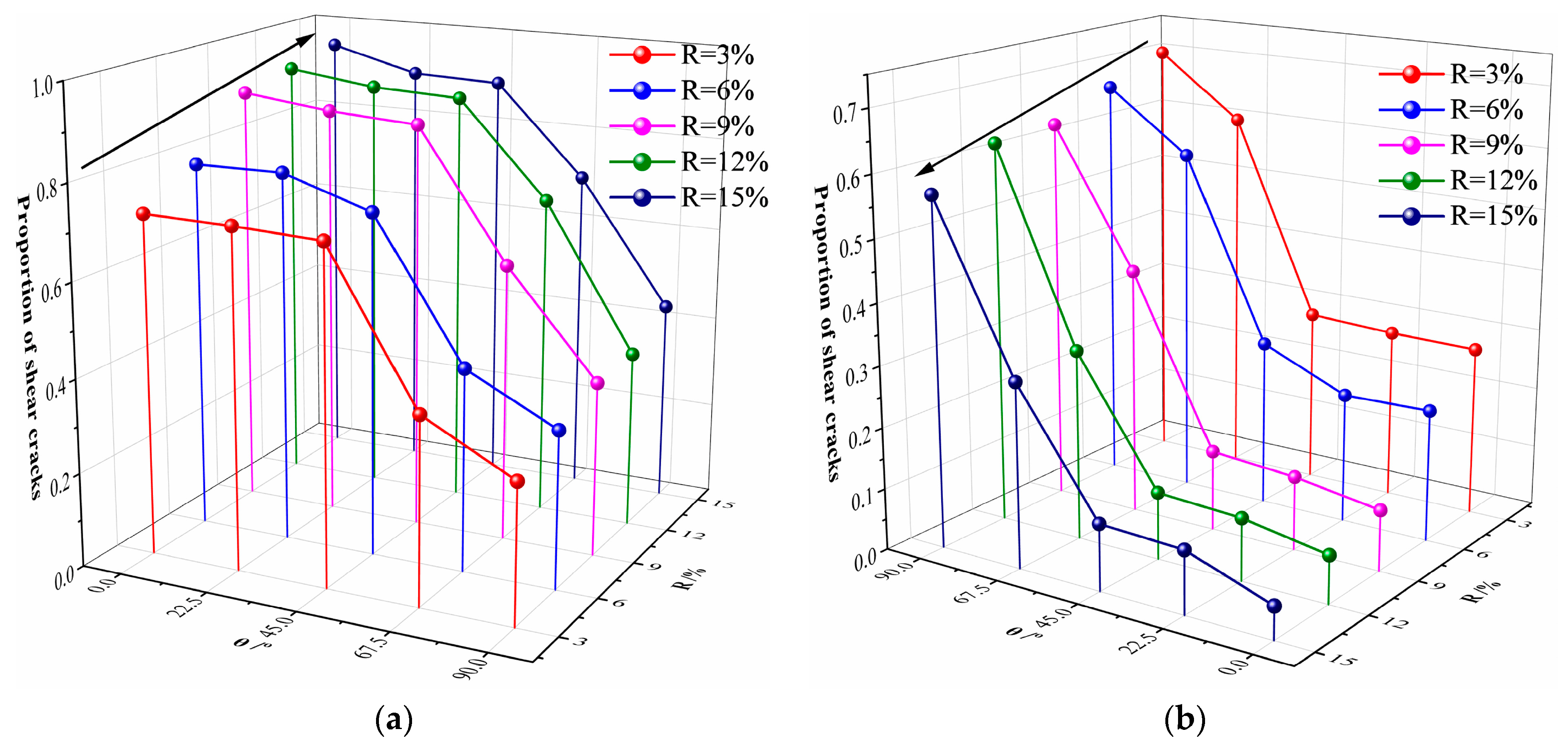
Figure 5 shows the proportion of tensile and shear cracks in the destruction of yellow sandstone specimens. With the increase in the fissure ratio, the proportion of tensile cracks keeps increasing, while the proportion of shear cracks keeps decreasing. With the increase in the fissure inclination angle, the proportion of tensile cracks in the destruction of specimens decreases overall while the proportion of shear cracks increases. When the fissure inclination angle is between 0° and 45°, the proportion of tensile and shear cracks changes very little. However, when the fissure inclination angle exceeds 45°, the proportion of tensile cracks decreases sharply, and the proportion of shear cracks increases sharply with the increase in the fissure inclination angle. Based on the comprehensive information of the crack field, principal stress field, and displacement field and the proportion of tensile–shear cracks at the destruction of yellow sandstone specimens, the failure modes of Brazilian disk specimens are classified as shown in
Table 3.
From
Table 3, it can be seen that when θ = 0° and 22.5°, the yellow sandstone specimens under different fissure ratios all undergo tensile failure; when θ = 45° and 67.5°, as the fissure ratio increases, the yellow sandstone specimens transform from tensile–shear composite failure to tensile failure; and when θ = 90°, the yellow sandstone specimens under different fissure ratios all undergo tensile–shear composite failure. Since the fissures in this paper are randomly generated, the centroids of different fissures are also randomly distributed. During the loading process, the main crack will expand and extend through different initially existing fissures, which will cause the main cracks of the specimen to deviate from the center loading position, thereby generating shear cracks. As the fissure inclination angle increases, the yellow sandstone specimens all transform from tensile failure to tensile–shear composite failure.
3.3. Mechanism of Crack Propagation and Evolution
The analysis of the crack initiation, propagation, and penetration processes during the loading of the specimens is of great significance for revealing the macroscopic and microscopic failure mechanisms of the yellow sandstone specimens. Due to the limitations of the article’s length, in this section, only the crack propagation characteristics of five different conditions of yellow sandstone specimens containing randomly distributed fractures during the Brazilian splitting test are analyzed, as shown in
Figure 6 and
Figure 7. In
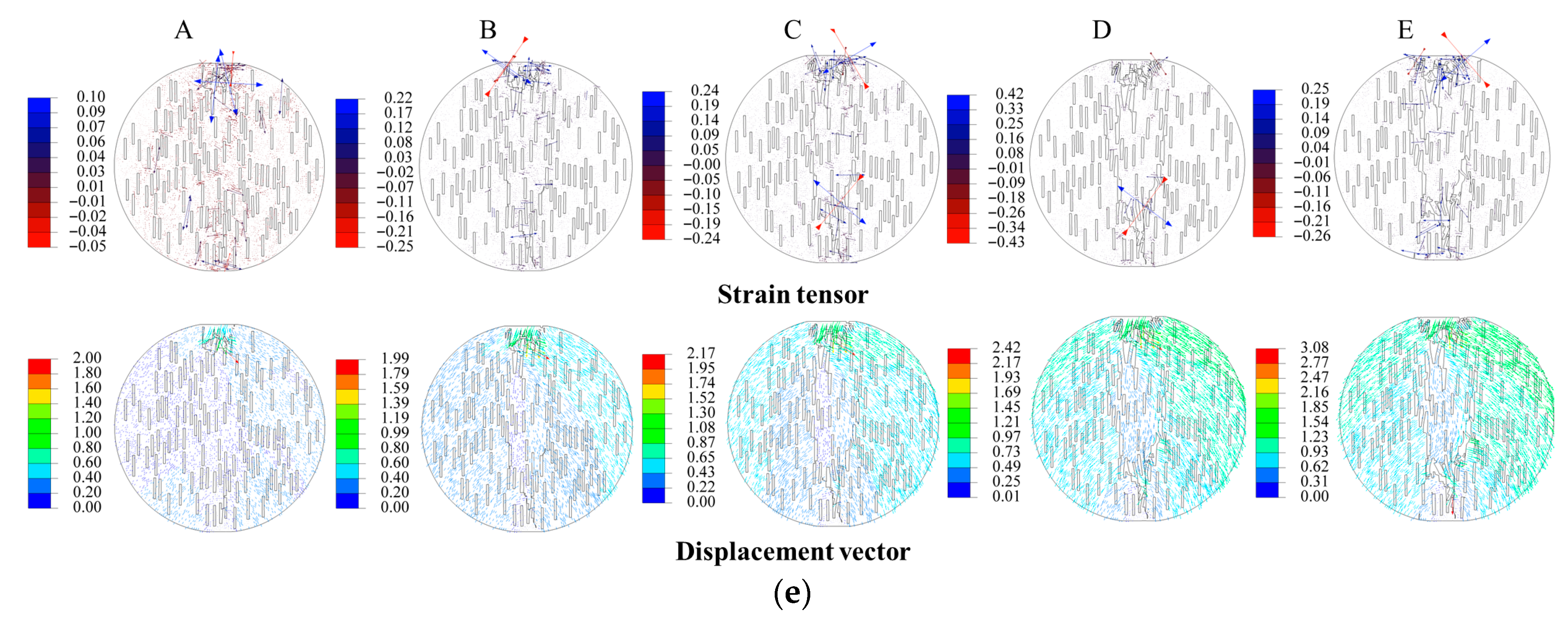
Figure 6, we select a strain tensor and displacement vector cloud map to illustrate the expansion and evolution process of the internal crack of the specimen as it is subjected to loading.
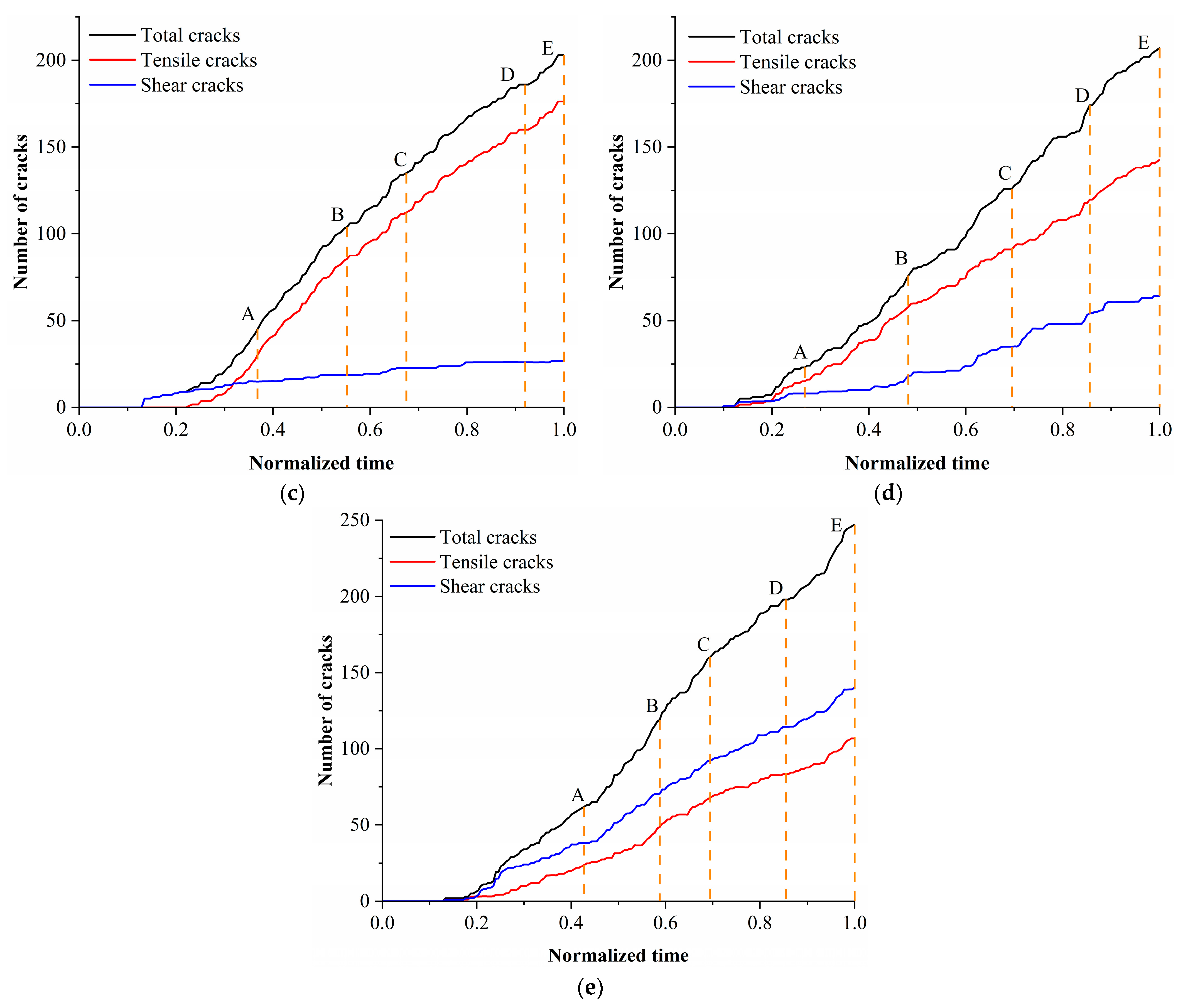
Figure 7 shows the number of total cracks, tensile cracks, and shear cracks with the loading time. The specific analysis is as follows:
(1) When θ = 0° and R = 3%, the main crack first initiates at the upper part of the specimen and continuously extends downward (point A) as the loading progresses. When encountering an initial crack, it instead extends towards the existing crack and connects with it, and subsequently, the main crack expands between the cracks, making the initial crack a part of the main fracture surface (point B). As the specimen undergoes loading, the main crack continuously extends downward in this pattern until the main fracture surface of the specimen is completely penetrated (point E), and the specimen loses its bearing capacity. Due to the influence of the initial crack, the main fracture surface undergoes a certain degree of vertical offset in the loading direction, with a relatively small overall offset, and the cracks generated throughout the loading process are mainly tensile cracks.
(2) When θ = 22.5° and R = 6%, when θ = 45° and R = 9%, and when θ = 67.5° and R = 12%, the evolution characteristics of the main crack during the test loading process are relatively similar. The main crack first initiates at the upper part of the specimen and then extends downward as the loading continues. When it encounters the initially existing cracks, it turns to extend along the initially existing cracks. Affected by the initially existing cracks, the main crack undergoes a certain offset along the vertical loading direction, and the degree of offset is closely related to the inclination angle of the crack. When θ = 22.5° and R = 6%, a crack appears at the bottom of the specimen when the loading reaches point C. As the loading process continues, it extends between the initially existing cracks, which can be regarded as a secondary crack. This crack extends towards the upper left.
(3) When θ = 90° and R = 15%, the main cracks of the specimen start to propagate at the top and bottom of the specimen, respectively. As the loading process continues, they expand continuously. When encountering initial cracks, they will turn to the existing initial cracks and expand between the cracks to connect the independent cracks. When the loading reaches point E, the main cracks that have expanded upwards and downwards in the middle of the specimen penetrate each other, and the specimen loses its bearing capacity. The test is terminated. At the time of specimen failure, the number of shear cracks is greater than that of tensile cracks, and the failure mode of the specimen is a combined failure of tension and shear.
4. Conclusions
(1) The Brazilian tensile strength of yellow sandstone shows an overall declining trend as the fissure ratio increases, which is due to the increase in the density of fissure defects, resulting in weakened bearing capacity. The influence of the fissure inclination angle on the Brazilian tensile strength exhibits significant non-monotonicity: at a low fissure ratio (R = 3%), the strength shows a “decrease–increase–decrease” trend; at medium and high fissure ratios (R ≥ 9%), the Brazilian tensile strength continuously increases with the increase in the fissure inclination angle, indicating that there is a critical threshold for the weakening effect of the fissure inclination angle on strength.
(2) The fissure ratio plays a dominant role in the deviation of the failure path: when θ ≤ 67.5°, as R increases, the main crack gradually deviates from the loading axis from the central vertical failure, and the guiding effect of the initial crack on crack propagation is enhanced; when θ = 90°, due to the crack being parallel to the loading direction, the deviation degree is the smallest. Microscopic crack statistics show that as R increases, the proportion of tensile cracks increases; as θ increases, the contribution of shear cracks is significantly enhanced (after θ > 45°, the proportion of shear increases sharply), indicating that the inclination angle induces shear slip by changing the stress transmission path.
(3) The propagation of the main crack is controlled by the spatial interaction of the initial fissures: when the crack encounters the fissure, it deflects and extends along the fissure boundary, allowing isolated fissures to connect and the crack to jointly form a penetration fracture surface. Under the coupling conditions of high inclination angle (θ = 90°) and high fissure ratio (R = 15%), the crack initiates from both the top and bottom of the specimen, eventually penetrating in the middle, accompanied by significant shear slip behavior, confirming the microscopic mechanism of combined tensile and shear failure.

