Abstract
Gas injection displacement technology plays a critical role in enhancing coalbed methane (CBM) and mine gas extraction efficiency. Numerical simulation is essential for revealing multi-field coupling mechanisms and optimizing process parameters, effectively addressing challenges such as high field test costs and limited laboratory scalability. This study systematically reviews progress in modeling physical fields (e.g., flow and diffusion), focusing on multi-physical field coupling mechanisms and permeability model evolution. It conducts iterative numerical model analysis—from basic flow–diffusion to fully coupled THMC models—compares simulation software (COMSOL shows greater coupling depth and compatibility than COMET3), and characterizes key mechanisms. By systematically reviewing the key advancements in the fields of numerical simulation in recent years (including important achievements such as the Buddenberg–Wilke equation and the improved Palmer–Mansoori model), a decision-making framework was proposed based on these achievements, covering “Multi-physical Field Coupling Equation Selection, Key Parameter Calibration, Permeability Equation Selection, Model Validation and Error Correction” simulation error ≤10% in heterogeneous coal seams. Although general-purpose tools enable high-precision multi-physics coupling, improvements are still needed in modeling flow–diffusion mechanisms, heterogeneity, and chemical field integration. This study provides a systematic methodological reference for the engineering application of gas injection displacement numerical simulation, and the framework constructed hereby can also be extended to shale hydraulic fracturing and other related fields.
1. Introduction
As a fundamental component of the global energy mix, coal’s safe green development and synergistic greenhouse gas emission reduction are key challenges under the “dual-carbon” strategy. Traditionally, coal mine gas (methane) was managed via ventilation; now gas extraction supplements ventilation as the core method. However, complex geological conditions (varying depths, stress, gas content) hinder collection and utilization, making efficient CBM/mine gas extraction a research hotspot.
Gas injection displacement technology enhances CBM recovery and gas extraction efficiency by injecting CO2/N2, with the dual benefits of energy recovery and CO2 sequestration. It applies to two scenarios: surface well CBM development (focused on CO2 sequestration and efficient methane recovery [1,2]), and underground gas disaster prevention suppressing CBM protrusion via borehole gas injection [3]. Scholars have verified its feasibility and accumulated data through laboratory experiments [4,5] and field trials [6,7]. Numerical simulation, as a tool to reveal the gas injection multi-field coupling mechanism and optimize parameters, compensates for high field test costs and limited laboratory scales [8,9], becoming key for in-depth research. Figure 1 (from CiteSpace analysis of literature from 2015 to 2025) shows keywords’ co-occurrence and evolution, indicating growing research on gas injection displacement numerical simulation, with progress in CO2 injection–storage, simulation models, and permeability model evolution—highlighting simulation’s role in unraveling displacement mechanisms.
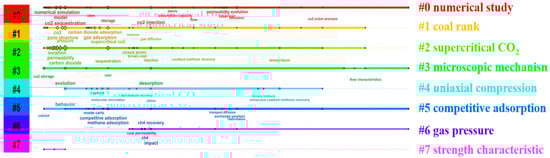
Figure 1.
Gas injection displacement research hotspots (2015–2025) and keyword co-occurrence (CiteSpace 6.3.R1).
Gas injection displacement involves multi-field coupling of flow–diffusion–adsorption/desorption–stress–temperature–chemistry, constrained by complex geological conditions. Numerical simulation is pivotal for clarifying these mechanisms and optimizing applications. Recent years have seen many mathematical models characterizing physical fields’ principles, coupling mechanisms, and evolution, while simulation has advanced in multi-field coupling [10,11,12] and permeability dynamic characterization accuracy [13,14]. Yet, with refined engineering demands, two limitations emerge: (1) a lack of systematic geological adaptation methodology—coupled equation selection, permeability characterization, and parameter acquisition rely on simplifications/empirical estimations in complex scenarios, without systematic matching logic; and (2) insufficient integration depth—previous studies [15] failed to systematically address urgent issues (precise flow–diffusion characterization, missing THMC (Thermal–Hydraulic–Mechanical–Chemical) full coupling, fracture non-homogeneity dynamic portrayal, field-laboratory parameter synergistic inversion), hindering the technology’s large-scale and precise application. Thus, this review aims to systematically optimize the gas injection displacement numerical simulation framework, with the following objectives:
- (1)
- Sort out the development of modeling theories for each physical field, analyze the coupling mechanisms of multi-physical fields, summarize the evolution and characteristics of permeability models, and provide a theoretical basis for the refinement of multi-field coupling models.
- (2)
- Sort out numerical models at different stages, summarize their technical advantages, compare the characteristics of simulation software, and propose a decision tree of “Multi-physical Field Coupling Equation Selection, Key Parameter Calibration, Permeability Equation Selection, Model Validation and Error Correction” by integrating model iteration, parameter integration, and error control logic, so as to provide a framework for improving simulation accuracy and engineering applicability.
- (3)
- Analyze the bottlenecks of multi-field coupled simulation, and propose optimization paths (refined gas transport characterization, heterogeneous modeling, THMC full coupling, cross-scale parameter collaborative inversion systems) to solve the core problems in current simulation, such as flow diffusion, chemical coupling, fracture anisotropy, and key parameters relying on experience.
2. Research Methodology
This mini-review was conducted following a systematic approach guided by the Preferred Reporting Items for Systematic Reviews and Meta-Analyses (PRISMA, v4.6.1.617, Prisma Labs, Palo Alto, CA, USA) guidelines to ensure comprehensiveness and reproducibility. The literature search was performed across two major academic databases: Web of Science Core Collection and Scopus. The search strategy utilized key terms and their Boolean combinations, such as (“coal seam” or “coalbed methane”) and (“gas injection” or “ECBM”) and (“numerical simulation” or “modeling”) and (“COMSOL” or “COMET3”). The search was confined to articles published between 2015 and 2025.
The study selection process involved three key stages, as detailed in the PRISMA flow diagram (Figure 2):
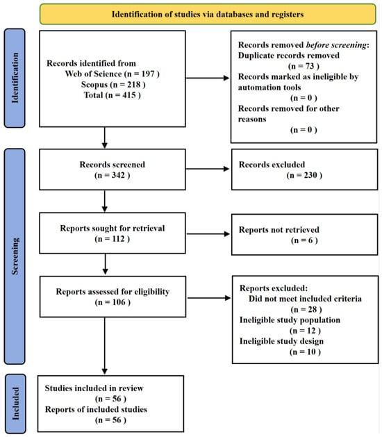
Figure 2.
PRISMA flow diagram illustrating the literature identification, screening, eligibility, and inclusion process for this systematic review.
Identification: The initial database searches yielded 415 records.
Screening: After removing 73 duplicates, 342 unique records were screened based on their titles and abstracts. Of these, 230 records were excluded as they did not meet the pre-defined criteria at this stage.
Eligibility: The full texts of the remaining 112 articles were sought for retrieval, of which 106 were successfully accessed. These 106 articles were thoroughly assessed for eligibility. A further 50 articles were excluded for specific reasons: not meeting the inclusion criteria (n = 28), ineligible study population (n = 12), or ineligible study design (n = 10). Ultimately, 56 studies were identified as relevant and form the basis of this mini-review. The entire process is summarized in Figure 2 to enhance transparency.
3. Theory of Multi-Physics Field Modeling for Gas Injection Displacement
3.1. Gas Migration Theory (Flow, Adsorption/Desorption, and Diffusion)
Darcy’s law was introduced in 1856 by Darcy through sand column flow tests [16]:
In the equation: VD represents the flow velocity, k is the permeability, μ is the viscosity, and ∇pf is the pressure gradient.
The law assumes linear gas flow and only applies when the Reynolds number is 1–10. Excessive flow rates or non-Newtonian fluid behavior can cause non-Darcy flow [17,18,19]. As shown in Figure 3: there is a minimum pressure gradient threshold in Zone A (low-speed non-Darcy flow zone) for low-speed flow, below which there is no flow, and beyond which the flow rate rises slowly with the gradient but does not follow a linear trend; the flow growth rate tends to slow down due to inertial effects deviating from linearity at high hydraulic gradients in Zone C (high-velocity non-Darcy-flow zone). For low-permeability first-mined coal seams, low-velocity gas flow exhibits the Klinkenberg effect; neglecting this leads to overestimated gas pressure [20]. At this point, the description of gas flow needs to be corrected on the basis of continuous flow through the Klinkenberg effect [21]:
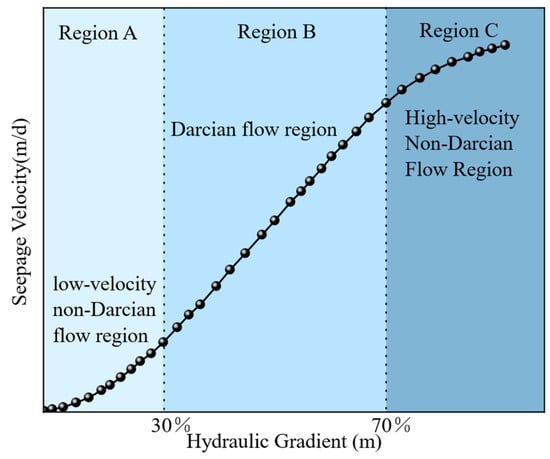
Figure 3.
Hydraulic gradient–flow velocity relationship curve.
In the equation: kapp is the apparent permeability coefficient, and bK represents the Klinkenberg factor.
As a porous medium, coal exhibits strong adsorption capacity for CBM. The Langmuir monolayer adsorption equation (1916), validated by numerous scholars, stands as a classic isothermal adsorption model. Other widely used alternatives include the D-A (Dubinin–Astakhov), BET (Brunauer–Emmett–Teller), and D-R (Dubinin–Radushkevich) models [22,23,24]. Figure 4 compares adsorption models (Langmuir, BET, D-A, D-R). The scores (1–5) in Figure 4 are based on a semi-quantitative assessment derived from a comprehensive review of the literature and the models’ typical performance in practice. The evaluation criteria are as follows: computational efficiency (1 = low, 5 = high): based on model complexity and computational resource demands; parameter complexity (1 = simple, 5 = complex): based on the number and difficulty of obtaining required parameters; fitting accuracy for CH4 (1 = poor, 5 = excellent): based on reported goodness-of-fit in studies; fitting accuracy for CO2 (1 = poor, 5 = excellent); applicability to multi-gas (1 = single-gas, 5 = multi-gas): assesses the model’s capability to handle competitive adsorption. Models may receive identical scores in a category if their performance in that specific aspect is deemed comparable based on the literature consensus.
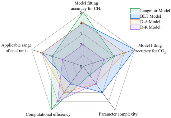
Figure 4.
Radar plot comparing the multidimensional properties of coal body gas adsorption models.
Langmuir is widely used for simplicity; D-A fits CO2 better, and all except D-R apply to CH4/CO2 [25,26]. With only two unknown variables, the Langmuir equation offers simplicity in solution and reasonable accuracy, making it widely employed in numerical simulations to characterize gas adsorption/desorption. The Extended Langmuir (EL) model, an advancement of the traditional Langmuir model, is designed to more precisely capture multilayer adsorption behavior [27]. It circumvents the singularity at saturated vapor pressure that plagues the BET and D-A models, preserves the simplicity of the original Langmuir model, and substantially enhances the fitting accuracy of multi-gas adsorption data. EL model achieves these improvements by extending the classic Langmuir theory to multi-component adsorption without introducing the mathematical complexities of the BET and D-A models. Unlike the BET model, which can become singular at saturated vapor pressure, and the D-A model, which requires more empirical parameters, the EL model avoids these pitfalls by utilizing a competitive adsorption formulation based on partial pressures. It preserves the simplicity and computational robustness of the original Langmuir model, requiring only the Langmuir constants for each gas, while significantly enhancing accuracy for gas mixtures by accounting for the competitive occupancy of adsorption sites. Its expression is as follows:
where Cpr is the adsorption state content of gas r, ρra is the density of gas r under the standard condition, ρc is the density of the coal body, ar is the limiting adsorption capacity of gas r, br is the adsorption equilibrium constant of gas r, pr is the equilibrium partial pressure of gas r, and the subscripts r = 1 and 2 denote the values of the corresponding variables of the gas and the injected gases in that order.
Coal seams have a complex multi-level pore structure. The coal matrix pores serve as both gas adsorption sites and gas transport channels. Gas first diffuses through the matrix micropores to the fracture edges, and then seeps under the action of pressure difference, forming a dynamic equilibrium of the matrix–fracture pressure gradient. Gas diffusion in coal is mainly through fine pores and can be further classified into Fickian diffusion, Knudsen diffusion, and transition diffusion based on the Knudsen number. However, in reality, these three diffusion modes are interrelated [28]. Based on the gas diffusion patterns in coal pores, scholars have developed single-pore, dual-pore, and multi-pore diffusion models. However, the single-pore model relies on the assumption of uniform isotropy, which conflicts with the heterogeneity of coal. It can only describe the diffusion in coal with a single pore structure and cannot account for the complex pore structure [29,30,31]. The single-pore model is overly simplified due to its assumption of a homogeneous sphere, which leads to systematic prediction bias and an inability to capture the dual-scale transport mechanism in coal. In contrast, the dual-pore model (based on Fick’s law) is quantitatively superior, as it resolves two distinct diffusion coefficients for the macropores and the matrix that can differ by orders of magnitude [32]. This critical advantage is conclusively demonstrated by the direct quantitative comparison in Table 1. The data show that the dual-pore model achieves near-perfect accuracy (R2 > 0.998) by utilizing diffusion coefficients differing by five orders of magnitude, thereby realistically characterizing the distinct fast (macropore) and slow (micropore) diffusion paths. Meanwhile, the single-pore model yields significantly lower fitting accuracy (R2 ≈ 0.9666–0.9753) with its single, inadequate diffusion coefficient, resulting in a failure to accurately describe the entire gas desorption–diffusion process, particularly the initial rapid gas release [33].

Table 1.
Quantitative comparison of the single-pore and dual-pore diffusion models based on Liu et al. [33].
As shown in Figure 5, gas flows in the coal’s natural fracture network (cleat system) following Darcy’s law, with its transport rate controlled by fracture openness, connectivity, and inhomogeneity. During gas injection, the fracture pressure gradient drives the injected gas to preferentially migrate along dominant flow pathways. Mathematically, this Darcy-based flow in the fracture system can be described by the following equation:
where pmgi is the partial pressure of the component i in coal matrix, and pfgi is the partial pressure of the component i in fractures. μgi is the dynamic viscosity of component i, and bk is the Klinkenberg factor.
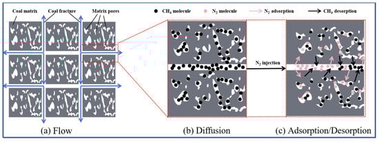
Figure 5.
Schematic diagram of gas flow, diffusion, and adsorption/desorption in the coal seam.
The injected gas diffuses into coal matrix pores through the fracture–matrix interface: the matrix pore network provides a large specific surface area, and the gas diffusion path is nonlinearly meandering, with its diffusion coefficient closely related to temperature, pressure, and pore fluid properties. Gas storage on the matrix surface via physical adsorption conforms to the monomolecular layer adsorption behavior described by the EL equation. Notably, the gas injection process—along with changes in gas adsorption—causes matrix expansion/contraction, which in turn affects fracture flow and diffusion paths. The mass balance and adsorption-related processes in the matrix can be captured by the following equation:
where τi is the desorption time of the component i, Mgi is the molar mass of component i, R is the gas molar constant, T is the temperature in the coal seam, ρsgi is the gas density of component i in the normal state, ρc is the density of coal, and VLi is the adsorbed gas content of component i in a unit mass of coal.
3.2. Hydraulic and Chemical Fields
The core of the hydraulic field is the migration process of gas (CH4, CO2/N2) and water in the matrix–fracture dual-pore system of coal seams. After gas injection, CO2 preferentially enters the fracture channels and comes into contact with and dissolves in the formation water in the fractures, which is the starting point of the hydraulic field triggering the chemical field effect. The dissolution of CO2 in water will cause a series of reactions: first, CO2 combines with water to form carbonic acid (H2CO3), and carbonic acid further dissociates into H+, HCO3−, and even CO32−, making the fracture water weakly acidic. This acidic water will migrate along the hydraulic gradient in the fractures and then chemically react with minerals in the coal. Common carbonate minerals in coal, such as calcite and dolomite (CaCO3), will react with H+ in the acidic water, leading to mineral dissolution; at the same time, a small number of sulfides such as pyrite in the coal will also dissolve, releasing ions such as Fe2+. The direct result of these reactions is the removal of mineral blockages in the fractures, expanding the pore and fracture channels, and thereby changing the key parameters of the hydraulic field. Simulation shows that mineral dissolution can increase the porosity of the coal seam by 15–30%, and the change in permeability will in turn affect the migration efficiency of fluids in the hydraulic field [34], accelerating the diffusion of CO2 and the desorption and migration of CH4. If only the water–gas two-phase flow is considered and the chemical effect is ignored, the permeability change in the later stage of gas injection will be underestimated: on the one hand, the early mineral dissolution increases permeability, and if the chemical field is not coupled, the gas injection efficiency will be misjudged; on the other hand, after long-term gas injection, dissolved Ca2+ and Fe2+ may re-precipitate (secondary precipitation of CaCO3), or fine particles produced by the dissolution of clay minerals may clog the fractures, leading to a decrease in permeability. This “first increase then decrease” lag effect can only be captured through the coupling of water and chemistry. In addition, acidic water will also change the hydrophilicity of the coal surface, affecting the relative permeability of water and gas, which also requires adjusting the relative permeability curve in the hydraulic field through a coupled model. The coupling of the two is the key to restoring the true process of coal seam gas injection and is also a necessary prerequisite for improving the prediction accuracy of core indicators such as permeability and CH4 recovery rate in the model. The governing equations commonly used for simulating this hydraulic–chemical coupling are summarized and compared in Table 2.
Table 2.
Comparison of hydraulic and chemical field control equations and their specificities.
3.3. Thermo-Mechanical Response Mechanism of Coal Body Deformation
Besides flow, diffusion, adsorption/desorption, and hydraulic–chemical field effects, gas injection displacement is also influenced by temperature and stress fields [36,37]. Changes in these two fields can disrupt the coal seam’s original dynamic equilibrium, forcing it to reestablish balance. During gas injection displacement, the gas adsorption/desorption reactions triggered by injected gas are accompanied by heat transfer, causing coal seam temperature changes. Studies show that as temperature rises, the Langmuir volume constant VL changes slightly, while the adsorption equilibrium constant PL decreases significantly—promoting desorption; alongside temperature, higher adsorption pressure and smaller coal particle size both increase gas desorption volume; coal functional group types affect the microscopic mechanism of adsorption exotherm; and elevated temperature reduces adsorption, while increased pressure stabilizes it [38,39]. The coupled equations for the temperature field during gas injection displacement are presented in Table 3.
Table 3.
Comparison of temperature field control equations and their specificities.
The force is the fundamental cause of the deformation and movement of the coal body; gas injection displacement of pre-drilled holes will cause plastic damage to the coal body in the mining space and around the holes, while the coal body unaffected by mining will remain in an elastic state of deformation. According to the assumption, the coal body is a linear elastic body, which will be elastically deformed by the stratum stress and fluid pressure and other effects. A tiny representative element volume (REV) is arbitrarily taken inside the coal body with side lengths dx, dy, and dz, as shown in Figure 6. The REV is subjected to both surface stresses and volume forces, which are uniformly distributed forces.
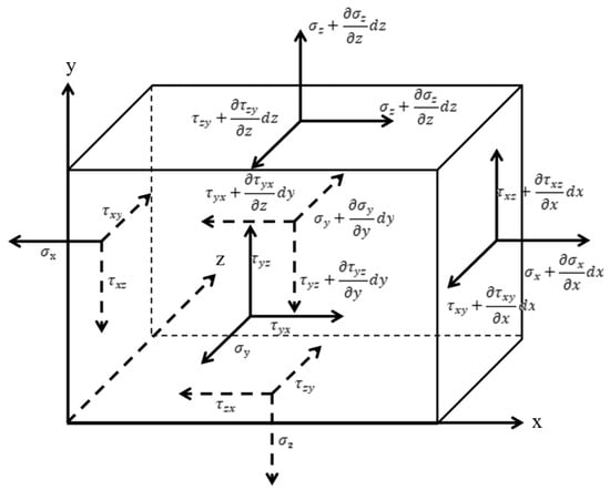
Figure 6.
Schematic representation of stress balance of representative units in the coal seam.
Coal stress field mathematical models are divided into two main categories: First, the uniaxial strain assumption (Figure 7a), which ignores lateral displacement and considers only the strain caused by overlying pressure, is applicable to the analysis of a wide range of coal seams, and the classical permeability model constructed based on it couples the fracture compressibility and pore permeability relationship, while other studies derive the horizontal effective stress change and establish an exponential permeability model. Second, the triaxial compressive strain model considers three-dimensional stress–strain (Figure 7b), which is more accurate in analysis but complex in modeling, e. g., the internal expansion coefficient λ is introduced in the triaxial state, and a new permeability model is established to quantify the effect of matrix–fracture interaction and creep on permeability [42,43,44].
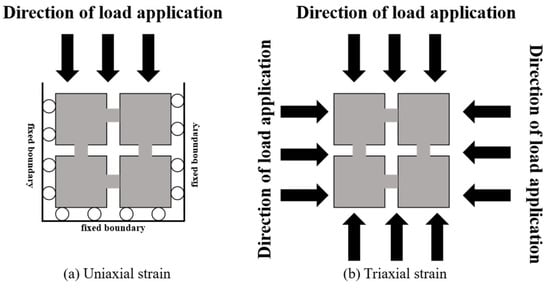
Figure 7.
Schematic diagram of uniaxial strain condition and triaxial stress condition of stress field.
Coal matrix deformation (induced by adsorption/desorption behavior, stress, and temperature changes) directly affects the fracture rate and permeability of coal seams. Early studies assumed that the coal matrix was incompressible (Biot coefficient = 1), and analyzed the adsorption–flow interaction by treating the contraction/expansion of the matrix and skeleton as a unified process. Subsequent studies found that there was a “balance lag” phenomenon in the gas diffusion of the matrix: its contraction/expansion effect could not be ignored, so the Biot coefficient was revised to the range of 0 to 1 [45,46]. Currently, it is common to introduce an adsorption expansion/desorption contraction term into stress/strain equations (e.g., adsorption strain is proportional to gas content) and convert it into a pore pressure-controlled strain term. This frees the permeability model from sole reliance on effective skeleton stress, enhancing the prediction of late-stage CBM permeability rebound [47]. The strain caused by adsorbed gas in the coal seam is volumetric strain and is spatially uniform. Based on the theory of elastic mechanics of porous media and considering the effects of ground stress, gas pressure, thermal strain, and adsorption strain, the total strain of the coal body is
where G is the shear modulus, K is the bulk modulus, αm and αf are the Biot coefficients of the coal matrix and fracture, Pm and Pf are the fluid pressures in the coal matrix and fracture, αT is the coefficient of thermal expansion, T is the temperature of the coal seam, εs is the volumetric strain of the coal matrix induced by the adsorption of the gas, δij is the Kronecker function, and δij = 1 when i = j; δij = 0 when i ≠ j.
All variables involved in Section 3.2 and Section 3.3, including their definitions and corresponding units, are detailed in Table A1 in Appendix A.
3.4. Evolutionary Improvements in Permeability Modeling
Coal is usually treated as a dual-pore medium (matrix and fracture), so its structure needs simplification when building permeability models (Figure 8). Among dual-pore models (spherical, capillary tube, cube, etc.), the matchstick and cube models are most commonly used. For absolute permeability, the most widely applied models are the strain-based P&M model (power function form) and stress-based S&D model (exponential function form); typical absolute permeability mathematical models are shown in Table 4.
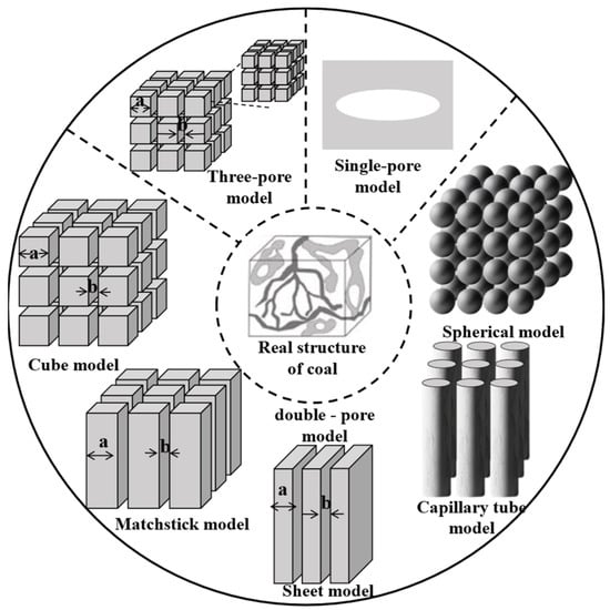
Figure 8.
Schematic diagram of the pore structure composition and simplified physical model of the coal body.
Table 4.
Mathematical model of absolute permeability.
Notably, permeability is greatly affected by water saturation and storage morphology: hydrates forming on particle surfaces have little impact on pore size, while those forming at pore centers or throats significantly narrow pores (or even block channels), leading to a sharp drop in permeability [48]. Relative permeability (effective permeability K(Sh)) refers to the permeability of a single-phase fluid flowing in a porous medium with specific hydrate saturation. For two-phase flow, aqueous phase permeability is called water relative permeability K(rw), and gas phase permeability is gas relative permeability K(rg). As shown in Figure 9, gas–water two-phase flow is divided into Zone A (pure gas flow) and Zone B (gas–water competitive flow). Coal matrix shrinkage and the Klinkenberg effect alter pore structure to affect the permeability of both zones; low-pressure dynamic pore changes (e.g., left side of Zone B) can enhance gas-phase flow capacity. Scholars have developed various gas–water two-phase flow relative permeability models as shown in Table 5.
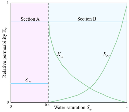
Figure 9.
Typical relative permeability of gas–water two-phase flow during the displacement process.
Table 5.
Mathematical model of relative permeability of gas–water two-phase flow.
3.5. Mechanism Analysis of THMC Multi-Field Coupling System in Gas Injection Displacement
During the gas injection displacement process, the gas migration field, water migration field, stress field, and temperature field of the coal seam interact through complex nonlinear mechanisms, thereby forming a multi-field coupling system of heat–fluid–solid. The core mechanism of this coupling relationship is summarized in Figure 10: in the process of gas injection displacement of CBM, the adsorption/desorption field is the starting point. The adsorption and desorption behavior of CH4 and CO2/N2 in the coal matrix not only regulates the gas saturation and relative permeability, but also links the gas adsorption, diffusion, and flow field in the form of source terms, and is accompanied by volume strain and changes in thermal properties (such as specific heat capacity); the flow field plays a core role in gas transport, with gas diffusing between the matrix and fractures, and its flow characteristics are affected by gas saturation, water density, and viscosity, as well as heat conduction and convection in the temperature field; the temperature field affects the fluid in the flow field and the thermal properties of the coal matrix through heat conduction and convection, and the heat effect generated by adsorption/desorption also feeds back to the temperature field, thereby establishing a channel for the interaction between heat and fluid. In the stress field, effective stress, porosity, and permeability are regulated by the interaction of multiple fields, and the change in stress in turn affects the flow and adsorption processes, thus achieving fluid–solid coupling. These fields work together in a coordinated manner around the transfer of matter, energy, and stress.
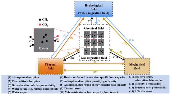
Figure 10.
Multi-physical field coupling mechanism in gas injection displacement technology.
4. Evolution and Engineering Decision System of Numerical Models for Gas Injection Displacement
4.1. Model Evolution and Software Capability Comparison
Numerical simulation of gas injection displacement has evolved significantly, as shown in Table 6, progressing from single-field descriptions to multi-physics coupling (e.g., from basic flow–diffusion models [53] to comprehensive THM/THMC frameworks [34,35]), from static parameters to dynamic multi-mechanism responses, and from theoretical verification to engineering application. This evolution, summarized in Table 6, is characterized by key advancements in permeability characterization (e.g., introducing the “elastic-plastic boundary point” [14] and the λ coefficient [54]) and in the calculation of critical parameters (e.g., employing the Buddenberg–Wilke equation for real-time mixed viscosity [55] and temperature-corrected Langmuir models [35,56]).
Table 6.
Comparison of different gas injection displacement numerical simulation models.
Software analysis reveals distinct strengths and application niches for COMSOL Multiphysics (Version 6.1) and COMET3 (Version 3.0). COMSOL, as a general-purpose platform, excels in flexibility, enabling the direct implementation of custom equations (e.g., the Extended Langmuir model, complex permeability laws) and the simulation of novel coupled processes like the full THMC coupling in this study. This makes it ideal for fundamental research and new model development, albeit with a steeper learning curve. In contrast, COMET3 is a dedicated, industry-proven simulator for coalbed methane. Its solvers are highly optimized for specific, large-scale production forecasting, offering superior computational efficiency for standard scenarios. However, its architecture limits the implementation of non-standard physics; it cannot directly solve fully coupled THM partial differential equations—leading to uncontrolled errors by neglecting temperature and water-phase impacts—and offers scant support for custom equations, hindering the modeling of complex processes like ternary gas competitive adsorption. Consequently, COMSOL is superior for developing and verifying innovative coupled frameworks, while COMET3 is more efficient for applied engineering and production prediction using established models.
The comparative analysis in Table 6 reveals that models achieving higher coupling depth (e.g., THM, THMC) and incorporating dynamic parameter mechanisms (e.g., real-time viscosity calculation, temperature-corrected adsorption) typically yield prediction errors below 10% for key outputs like gas migration rate and permeability. No single model is universally ‘best’; however, for predicting methane production in complex, non-isothermal CO2-ECBM scenarios, fully coupled THMC models demonstrate superior comprehensive performance by capturing a wider range of interacting physical processes. Under complex geological conditions, numerical simulation of gas injection displacement in coal seams faces challenges such as differentiated applicability of multiple models, high parameter sensitivity, and limited computational efficiency. A systematic review of the evolution of gas injection displacement mathematical models (Section 4.1) shows that no single model can universally address diverse geological characteristics (e.g., varying permeability, stress sensitivity, multiphase flow). Thus, a structured decision-making framework is needed to enhance the scientific rigor and engineering applicability of model selection.
4.2. Engineering Decision Trees: Hierarchical Decision Trees for Numerical Simulation of Gas Injection Displacement Models
Under complex geological conditions, numerical simulation of gas injection displacement in coal seams faces challenges such as differentiated model applicability, high parameter sensitivity, and limited computational efficiency. The systematic review in Section 4.1 confirms that no single model is universally applicable. Furthermore, analysis of high-precision models (with errors ≤10%) in Table 6 informed the construction of a four-dimensional decision-making framework (Figure 11) to enhance the scientific rigor and engineering applicability of model selection. This framework sequentially addresses four core questions to build confidence in simulation results, from theoretical foundation to practical reliability: (1) Governing physical equations? (Multi-physical Field Coupling Equation Selection); (2) Accurate input parameters? (Key Parameter Calibration); (3) Evolution of the core property—permeability? (Permeability Equation Selection); and (4) Trustworthy model output? (Model Validation and Error Correction). While aspects like mesh generation are important, this framework focuses on the most critical, high-level decisions impacting model accuracy and applicability. The decision-making process is as follows (Figure 11):
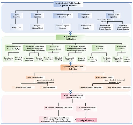
Figure 11.
Engineering decision tree for model optimization of gas injection displacement technology.
- (1)
- Multi-physics Field Coupling Equation Selection. (a) Flow equation: Darcy’s law is used. (b) Diffusion equations: two-pore diffusion model, Fick’s law dominant. (c) Adsorption/desorption equation: the EL equation. (d) Mechanical equation: Biot porous elasticity equation. (e) Thermal field equations: consider the influence of thermal effects using non-isothermal adsorption heat transfer equation; vice versa using isothermal adsorption heat transfer equation.
- (2)
- Key Parameter Calibration: Acquisition of key parameters for special geological conditions and different gas injection sources. Combined with experimental acquisition or historical data fitting to obtain relevant parameters such as gas adsorption parameters (Langmuir constants VL, PL), thermal expansion coefficients α, rock bridge structure parameters (internal expansion coefficients λ), coal seam porosity, fracture rate (φm, φf), gas dynamic viscosity coefficients (μ), gas diffusion coefficients (D), etc., inverted based on high-precision experimental or historical data.
- (3)
- Permeability Equation Selection:The selection is based on the dominant flow regime, which transitions at a critical water saturation of 40%—a threshold substantiated by THMC coupled simulations [58] and aligned with the flow regime transition identified in Section 3.4 (Figure 9).
- (a)
- Low water saturation ≤40%: In this gas–continuous-phase regime, absolute permeability, governed by stress-induced and adsorption-induced strain, is the controlling factor. The improved P&M model is selected to capture the evolution of absolute permeability under stress and sorption [20,55]. The classical P&M model is chosen if thermal effects are neglected and the stress–adsorption relationship is simplified.
- (b)
- High water saturation >40%: In this competitive gas–water two-phase flow regime, relative permeability effects dominate. The modified Brooks–Corey model is selected to account for complex pore structure and fluid-distribution effects, consistent with approaches in simulations of high-water-saturation ECBM processes [56]. The standard Brooks–Corey model can be used if stress and temperature corrections are unnecessary. The modified Brooks–Corey model can be used for correcting the effects of stress and temperature on relative permeability, and vice versa with the Corey/Brooks–Corey model to cover gas–water two-phase flow.
- (4)
- Model Validation and Error correction: When the error of CH4 pressure/seam permeability was >10%, the pore/fracture compression coefficients (Cm, Cf) were corrected by piezo mercury experiments, and the adsorption time constant (τ) was re-determined. Error ≤10%: output the final model to ensure that the simulation accuracy meets the engineering requirements (e. g., coal mine downhole gas injection displacement, surface coalbed methane development).
Compared to conventional static models with fixed parameters, the framework’s selection–calibration–validation–optimization closed-loop process provides a scientific decision-making system for optimizing both underground gas injection-enhanced drainage and surface CBM recovery designs.
4.3. Engineering Decision Tree Validation and Application Case Study
The engineering decision tree was validated using a five-well CO2-ECBM field trial in the 3# coal seam of the Qinshui Basin [59]. A two-dimensional Cartesian coordinate model (with dimensions of 200 m by 200 m) was established, and a five-point well pattern layout (with a well spacing of 283 m) was adopted, featuring constant 10 MPa injection pressure, 0.1 MPa production drainage pressure, and adiabatic no-flow outer boundaries. The model assumed constant injection and production pressures of 10 MPa and 0.1 MPa, respectively, to simplify the initial case study and facilitate a clear comparison, acknowledging that in field operations, these parameters typically vary over time. Input parameters were derived from experimental literature data, with incorporation of the temperature-coupled governing equations (refer to Section 3.2, Equation (7) to characterize thermal–mechanical–hydraulic (THM) interactions in permeability evolution.
Due to the scarcity of time-evolving field permeability data, the simulation results from Fang et al. [59]—whose model was field-validated—served as the benchmark. For this validation case, the decision tree was applied, leading to the selection of the THM coupling equations and the improved P&M model for permeability evolution. Key parameters (e.g., Langmuir constants, initial permeability, porosity) were primarily sourced from experimental data related to the Qinshui Basin 3# coal seam [59]. Where necessary, minor calibrations were made within physically reasonable ranges to achieve a history match with the initial production data.
Figure 12 presents a comparative analysis of permeability ratio (k/k0) evolution along the model diagonal between the present fully coupled THM model and Fang et al.’s isothermal model [59], under the condition of 10 MPa injection pressure and 5000-day simulation. The results show that the two models exhibit aligned permeability ratio trends: the relative deviation along the diagonal ranges from 5% (minimum at 9.4 m) to 8.1% (maximum at 169.8 m), and the permeability ratio calculated by our model is overall 5–8.1% higher than that of the benchmark model. Critically, the relative error reveals a distinct spatial pattern: it is minimized near the injection well (5% at 9.4 m) and increases progressively with distance, reaching a maximum in the far-field region near the production well (8.1% at 169.8 m). The prediction error was quantified using the relative error (RE) metric, defined in Equation (8):
where (k/k0)m,i and (k/k0)F,i are the permeability ratios from our model and the benchmark model at the i-th location, respectively.
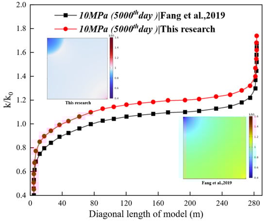
Figure 12.
Comparison of permeability ratio (k/k0) evolution between the fully coupled THM model and the isothermal model under 10 MPa injection pressure at 5000 days [59].
This divergence primarily stems from two mechanisms: (1) after 3000 days, the mutual cancelation of CO2 adsorption swelling and CH4 desorption shrinkage minimized effective stress impacts; and (2) the synergistic effects of late-stage production well permeability rebound and stabilized injection elevated whole-seam permeability above initial values. This mechanism of permeability influence has been verified [59]. The framework demonstrated ≤10% prediction errors, effectively addressing systematic deviations in prior thermal-neglected models and providing reliable guidance for CO2-ECBM parameter optimization. The discrepancies observed in Figure 12, particularly the minimal deviation at 9.4 m (closer to injection well) and the maximum deviation at 169.8 m (further into the reservoir), can be attributed to the coupled THM mechanisms. Near the injection well (e.g., 9.4 m), strong forcing (high CO2 pressure) dominates the permeability evolution, leading to better agreement between models. At farther distances (e.g., 169.8 m), the interplay between CO2 adsorption swelling, CH4 desorption shrinkage, and the resulting effective stress changes becomes more complex and spatially heterogeneous. Our fully coupled THM model captures the delayed permeability rebound in these regions more accurately than the isothermal model, which neglects temperature-mediated strain effects and their spatial variation, leading to the larger discrepancy.
It should be noted that the use of a two-dimensional model represents a simplification of the inherently three-dimensional gas injection process, adopted here for computational efficiency and conceptual clarity. While it serves the purpose of demonstrating the framework’s utility under controlled conditions, future applications should aim for 3D simulations to more accurately capture spatial heterogeneities and complex flow paths. In addition, although the constant-pressure assumption is adopted in this study to simplify the initial case, dynamic pressure changes in field operations significantly affect the coalbed methane displacement process: on the one hand, fluctuations in injection/production pressures directly disturb the adsorption–desorption equilibrium of CH4 and CO2, altering the displacement efficiency of the two gases; on the other hand, the dynamic evolution of pressure not only affects the fluid seepage pattern (e.g., triggering non-Darcy seepage) by changing the pressure gradient in the seepage field, but also causes dynamic changes in coal permeability through the effective stress effect, and the permeability changes in turn act back on the seepage process. In future work, we will conduct multi-physics simulations under dynamic pressure coupling to improve the model’s adaptability to field conditions.
5. Urgent Problems and Future Prospects
5.1. Precision Modeling of Flow–Diffusion Mechanisms
During the gas injection displacement process, gas transportation is controlled by both flow and diffusion fields. Current characterization often suffers from idealized distortions: the flow field is predominantly described by Darcy’s law, while the diffusion field is homogenized based on Fick’s law. In reality, flow behavior may exhibit complex nonlinear relationships, and diffusion involves mixed mechanisms of Knudsen and transition regime diffusion in nanopores, further modulated by pore surface roughness. To address these limitations, precise modeling of both fields is urgently needed:
- (a)
- For the flow field, it should be treated as a composite flow with nonlinear terms. The dominant flow equation should be selected based on flow velocity and pore size dynamics, choosing from the Darcy, Forchheimer, or Swartzendruber equations. As compared in Table 7, the Swartzendruber equation offers a more flexible framework for capturing non-Darcy behaviors that deviate from the quadratic velocity dependence of the Forchheimer model, making it potentially more accurate for complex fluid–coal interactions.
Table 7. Comparison of different flow control equations for coal seam gas injection.
- (b)
- For the diffusion field, a multi-mechanism quantification framework is required, delineating the dominant diffusion regime (Fick, Knudsen, or transition) based on pore size distribution from BET test data. It is crucial to note that the BET method has limitations in ultra-micropores, potentially introducing uncertainty. Thus, a surface roughness correction factor (obtained from experiment or molecular simulation) should be introduced to dynamically calibrate the diffusion coefficients.
5.2. Characterization of Anisotropic Fracture Networks
Fracture networks in deep coal reservoirs demonstrate intricate topological configurations characterized by fractal dimensions, with natural fracture apertures conforming to a Weibull distribution. Traditional dual-porosity models, however, approximate these structures using isotropic permeability tensors, resulting in significant deviations in the representation of key flow parameters. Although anisotropic permeability models based on tensor decomposition have been proposed by some scholars, and fractal geometry theory (e.g., Mandelbrot fractal dimension) and discrete fracture network models have been validated in the field of rock mechanics to describe inhomogeneous fractures [60], these models have not yet been integrated into the mainstream simulation framework of gas injection displacement. However, these models have not been integrated into the mainstream gas injection displacement simulation framework and lack field engineering validation. Future efforts should focus on the engineering adaptation of anisotropic models. The first priority is to develop an anisotropic permeability interface in numerical simulation software, integrating existing anisotropic permeability models into gas injection simulation platforms. This will enable the software to receive and compute anisotropic permeability parameters, thereby overcoming the traditional isotropic default setting. Secondly, the rationality and accuracy of anisotropic models should be validated by comparing simulation results before and after their application, based on field gas injection data and laboratory experimental results. Finally, based on the validation outcomes, the anisotropic model should undergo iterative optimization—refining its input parameter system to progressively enhance the accurate characterization of anisotropic features in coal seams.
5.3. THMC Full-Coupling Deficit Mitigation
The existing THMC coupling models have not comprehensively resolved the issue of chemical mineralogical changes during the interaction of CO2, water, and coal. For example, they do not meticulously calculate the dissolution and precipitation rates of minerals such as calcite. Moreover, they do not take into account the influence of the altered water absorption of the coal surface after mineral changes on gas flow, which results in inaccurate permeability predictions. Although some studies have attempted to incorporate chemical processes into the models [60], they either fail to thoroughly explore the dynamic processes of chemical reactions, or do not integrate chemical changes with permeability and mechanical deformation in real time. Additionally, they do not capture the hysteresis phenomenon where permeability increases due to short-term mineral dissolution and then decreases due to long-term clay particle clogging. There are also combined simulations using COMSOL and PHREEQC (a computer program for speciation, batch-reaction, and transport calculations), yet most of them are focused on sandstones and shales and not adapted to the specific structure of coal reservoirs. To bridge this gap, a COMSOL-PHREEQC coupled simulation framework can be constructed. First, employ the geochemical database of PHREEQC to track the dissolution–precipitation changes in coal minerals in real time [61]. Second, correlate the pore changes resulting from mineral reactions with the permeability model to dynamically update the permeability. Third, integrate experimental measurements of the water absorption changes in the coal surface to adjust the relevant parameters of gas–water flow. This approach enables the accurate capture of the hysteresis characteristics of permeability (i.e., increasing first and then decreasing), thereby making the THMC model more consistent with practical scenarios.
5.4. Joint Inversion of Key Parameters in the Field and Laboratory
Accurate acquisition of key parameters (e.g., gas adsorption constants (VL, PL)), diffusion coefficients (D), fracture compression coefficients (Cf), and other key parameters is the key to the reliability of the gas injection displacement model. There are significant discrepancies between current laboratory measurement conditions and actual geological environments. During gas injection, temperature and pressure variations induce dynamic parameter evolution, yet existing models treat these parameters as constants. Laboratory data are predominantly derived from small-scale core samples, whereas field parameter inversion relies on kilometer-scale inter-well monitoring data. This substantial spatial-scale mismatch (spanning multiple orders of magnitude) introduces experimental parameter errors that ultimately compromise model accuracy. The construction of the “laboratory calibration—field inversion—dynamic update” trinity framework is the key to breakthroughs; constructing a database containing coal rock microstructure and fundamental parameters by simulating the initial distribution characteristics of parameters under real stratigraphic conditions in the laboratory. Machine learning algorithms [62] are implemented to construct multiscale correlation models bridging microscale laboratory measurements with macroscale field datasets. The machine learning prediction results are used as the initial values, coupled with a mathematical model of gas injection displacement, and the key parameters are inverted by a history-fitting optimization algorithm (e.g., genetic algorithm) to construct a dual-drive inversion model. In the future, integrating geophysical data (e.g., seismic exploration) to constrain the inversion of geomechanical properties will be an important direction for improving the spatial characterization accuracy of model input parameters.
5.5. Extensibility of the Framework to Other Technologies and Reservoirs
The proposed four-dimensional decision-making framework, while developed for gas injection in coal seams, possesses inherent extensibility to other subsurface energy technologies, notably hydraulic fracturing in shale and tight sandstone reservoirs. The core logic—selecting governing equations, calibrating key parameters, choosing constitutive models, and validating against field data—remains universally applicable. Taking the study by [63] as a concrete example, which established a seepage–damage coupling model for hydraulic fracturing considering material heterogeneity and solved it using COMSOL, the workflow aligns closely with our framework. Adapting our framework for hydraulic fracturing simulations can be specified as follows:
- (a)
- Governing Equations Selection: The core at this stage is the coupling between geomechanics and fluid flow. For instance, an elastoplastic or elastic-damage constitutive model describing rock failure (e.g., the Mohr–Coulomb and maximum tensile stress criteria used in the reference) should be adopted and coupled with Darcy’s law or more complex non-Darcy flow equations.
- (b)
- Key Parameter Calibration: The key parameters to be calibrated become rock mechanical properties (e.g., elastic modulus, Poisson’s ratio, compressive/tensile strength) and the in situ stress field. These can be acquired through laboratory core tests or field measurements (e.g., hydraulic fracturing tests). The reference’s use of Weibull and log-normal distributions to assign heterogeneous mechanical and hydraulic parameters exemplifies the implementation of the “Key Parameter Calibration” step in addressing reservoir heterogeneity.
- (c)
- Constitutive Model Selection: At this stage, the focus shifts to selecting a fracture propagation model. Depending on the simulation focus, one might choose continuum methods (e.g., damage mechanics-based models like the one used in the reference) or discrete fracture network models.
- (d)
- Model Validation and Error Correction: Finally, the model must be validated and corrected against field data, such as microseismic monitoring events, fracturing treatment pressure curves, or production history data. The reference validated its model by comparing the simulated fracture initiation pressure against theoretical solutions from classical H-F and H-W equations and by aligning fracture patterns with engineering expectations.
6. Conclusions
- (1)
- This study systematically reviews the theoretical development and engineering application of numerical simulation for coal seam gas injection displacement, focusing on its core role in enhancing coal mine gas drainage and safety. It clarifies the modeling principles of key physical fields (flow–adsorption–diffusion, thermo–mechanical, hydraulic–chemical) and their coupling mechanisms: the flow field relies on Darcy’s law corrected by the Klinkenberg effect to characterize fracture flow; the adsorption/desorption field adopts the Extended Langmuir model to quantify multi-gas competitive adsorption; the thermo-mechanical field integrates Biot porous elasticity theory with adsorption-induced strain; the hydraulic–chemical field couples CO2 dissolution–mineral dissolution kinetics to reveal permeability evolution. Additionally, it summarizes the evolution of permeability models—from static constant assumptions to dynamic coupling of stress, adsorption, and chemical effects, laying a theoretical foundation for refined simulation of gas control.
- (2)
- This study traces the evolution of numerical models from basic flow–diffusion models to THMC full-coupling models, and compares the performance of simulation software: COMSOL demonstrates greater coupling depth and flexibility for complex scenarios, supporting customized equations and THMC nonlinear partial differential equation solving, whereas COMET3 is optimized for standard production forecasts. Based on this, a four-dimensional decision-making framework (“Multi-physical Field Coupling Equation Selection, Key Parameter Calibration, Permeability Equation Selection, Model Validation and Error Correction”) is proposed. Validation in the 3# coal seam of Qinshui Basin shows the framework controls simulation error ≤10%, effectively resolving the problems of empirical parameter selection and low model adaptability in traditional simulation. It provides a standardized technical path for optimizing underground gas injection drainage parameters and improving gas control efficiency.
- (3)
- This study identifies four key bottlenecks restricting the application of gas injection displacement simulation: imprecise flow–diffusion characterization (over-reliance on Darcy’s law, neglect of Knudsen diffusion in nanopores); insufficient fracture network anisotropy portrayal (isotropic permeability tensors failing to reflect fractal features); incomplete THMC coupling (inadequate integration of mineral dissolution–precipitation with permeability–mechanical deformation); and cross-scale parameter mismatch. The corresponding future research directions are proposed to address these issues: (1) refine gas transport modeling by classifying flow regimes (Darcy/Forchheimer/Swartzendruber) based on flow rate and pore size, and calibrate diffusion coefficients with surface roughness correction; (2) develop anisotropic permeability interfaces in simulation software, integrate discrete fracture network models, and validate with field data; (3) construct a COMSOL-PHREEQC coupled framework to track coal mineral reactions and capture permeability hysteresis; and (4) establish a “laboratory calibration-field inversion-dynamic update” parameter system, using machine learning to bridge micro–macro scale gaps. These efforts aim to develop high-precision simulation tools for coal mine gas control, promoting large-scale application of gas injection displacement technology in complex geological conditions.
Author Contributions
X.Y.: Methodology, Investigation, Writing—original draft; F.D.: Formal analysis, Writing—review and editing; Q.Z.: Conceptualization, Formal analysis, Writing—review and editing; Y.Z. (Yunfei Zuo): Writing—review and editing; F.T.: Investigation; Y.Z. (Yiyang Zhang): Data curation; Y.X.: Investigation. All authors have read and agreed to the published version of the manuscript.
Funding
This project was supported by the National Natural Science Foundation of China (52204196, 52374249).
Data Availability Statement
No new data were created or analyzed in this study.
Conflicts of Interest
The authors declare that they have no known competing financial interests or personal relationships that could have appeared to influence the work reported in this paper.
Appendix A
Table A1.
Variables corresponding to different chapters.
Table A1.
Variables corresponding to different chapters.
| Variables from Section 3.2 | Variables from Section 3.3 | ||
|---|---|---|---|
| thermal conductivity of the coal body, J/(m·s·K) | effective stress variation, PA | ||
| Qt | gas content, m3/t | Kp | bulk modulus of pores, MPa |
| constant volume specific heat of a coal body, J/(kg·K) | coal fracture adsorption volume strain, dimensionless | ||
| thermal strain coefficient, K−1 | Biot coefficient of coal matrix, dimensionless Biot coefficient of coal fracture, dimensionless | ||
| volumetric strain rate, s−1 | Langmuir pressure, MPa | ||
| phase change pressure coupling coefficient, dimensionless | Cpc | perimeter pressure sensitivity factor, MPa−1 | |
| w | pressure correction factor, Pa−1 | krg | relative gas-phase permeability, dimensionless |
| b | gas adsorption phase fraction, dimensionless | krog | relative permeability of gas-phase endpoints, dimensionless |
| effective specific heat capacity, J/(m3·K); effective thermal convection coefficient, J/(m2·s); effective thermal conductivity, W/(m·K) | krw | relative permeability of aqueous phase, dimensionless | |
| isothermal heat of adsorption/desorption of gases, kJ/mol | Krw0 | relative permeability of aqueous phase endpoints, dimensionless | |
| , Cgi and Cw | specific heat capacity of coal, gas mixtures and water, J/(kg K) | Sw | water saturation, % |
| Variables from Section 3.3 | Swr | bound water saturation, % | |
| K0 | initial penetration rate, mD | Sgr | residual gas saturation, % |
| Cf | coal fracture compression factor, MPa−1 | Seff | effective saturation, % |
| adsorption volume strain, % | pore size distribution parameters, dimensionless | ||
| initial porosity, porosity, dimensionless | a, b | empirical fitting parameters, dimensionless | |
| coal matrix compression factor, pore compression coefficient, MPa−1 | relative permeability of a phase, dimensionless | ||
| M | bulk modulus, MPa | endpoint relative permeability of a phase | |
| E | modulus of elasticity, MPa | dynamic viscosity of α- and β- phase fluids, P·s | |
| b | gas adsorption constant, MPa−1 | C, n | empirical constant, dimensionless |
| C1 | contribution weight of adsorption strain to porosity, dimensionless | saturation of the β-phase, dimensionless | |
References
- Ding, S.; Li, Y.; Zhang, M.; Xu, C.; Wang, S.; Gao, Y.; Yu, H.; Du, Y.; Ma, J. Holistic Review on CO2 Geological Storage Potential Evaluation. Energy Fuels 2024, 38, 19946–19965. [Google Scholar] [CrossRef]
- Zhou, L.; Feng, Q.; Chen, Z.; Liu, J. Modeling and Upscaling of Binary Gas Coal Interactions in CO2 Enhanced Coalbed Methane Recovery. Procedia Environ. Sci. 2012, 12, 926–939. [Google Scholar] [CrossRef]
- Gong, H.; Wang, K.; Wang, G.; Yang, X.; Du, F. Underground coal seam gas displacement by injecting nitrogen: Field test and effect prediction. Fuel 2021, 306, 121646. [Google Scholar] [CrossRef]
- Yang, H.; Zhou, K.; Chen, L.; Lu, X.; Kang, N. Differential Analysis of Various Moisture Phases on N2 Displacement of CH4 in Coal. ACS Omega 2024, 9, 15633–15640. [Google Scholar] [CrossRef]
- Zhou, K.; Yang, H.; Guan, J.; Si, Z. Study on the Differences between Various Gas Injection Sources in the Process of Coal Seam Methane Replacement by Gas Injection. ACS Omega 2022, 7, 37572–37580. [Google Scholar] [CrossRef]
- Yang, X.; Wang, G.; Du, F.; Jin, L.; Gong, H. N2 injection to enhance coal seam gas drainage (N2-ECGD): Insights from underground field trial investigation. Energy 2022, 239, 122247. [Google Scholar] [CrossRef]
- Yang, X.; Wang, G.; Ni, M.; Shu, L.; Gong, H.; Wang, Z. Investigation on Key Parameters of N2 Injection to Enhance Coal Seam Gas Drainage (N2-ECGD). Energies 2022, 15, 5064. [Google Scholar] [CrossRef]
- Asif, M.; Wang, L.; Panigrahi, D.C.; Ojha, K.; Hazlett, R. Integrated assessment of CO2-ECBM potential in Jharia Coalfield, India. Sci. Rep. 2022, 12, 7533. [Google Scholar] [CrossRef] [PubMed]
- Sarkar, S.; Singh, I.V.; Mishra, B.K. A simple and efficient implementation of localizing gradient damage method in COMSOL for fracture simulation. Eng. Fract. Mech. 2022, 269, 108552. [Google Scholar] [CrossRef]
- Fan, C.; Yang, L.; Wang, G.; Huang, Q.; Fu, X.; Wen, H. Investigation on Coal Skeleton Deformation in CO2 Injection Enhanced CH4 Drainage from Underground Coal Seam. Front. Earth Sci. 2021, 9, 766011. [Google Scholar] [CrossRef]
- Fang, H.-H.; Zheng, C.-S.; Qi, N.; Xu, H.-J.; Liu, H.-H.; Huang, Y.-H.; Song, S.-L. Coupling mechanism of THM fields and SLG phases during the gas extraction process and its application in numerical analysis of gas occurrence regularity and effective extraction radius. Pet. Sci. 2022, 19, 990–1006. [Google Scholar] [CrossRef]
- Cui, X.; Bustin, R.M. Volumetric strain associated with methane desorption and its impact on coalbed gas production from deep coal seams. AAPG Bull. 2005, 89, 1181–1202. [Google Scholar] [CrossRef]
- Gray, I. Reservoir Engineering in Coal Seams: Part 1—The Physical Process of Gas Storage and Movement in Coal Seams. SPE Reserv. Eng. 1987, 2, 28–34. [Google Scholar] [CrossRef]
- Liu, H.-H.; Rutqvist, J. A New Coal-Permeability Model: Internal Swelling Stress and Fracture–Matrix Interaction. Transp. Porous Media 2010, 82, 157–171. [Google Scholar] [CrossRef]
- Ma, X.; Zhou, A.; Cheng, X.; Cheng, C.; Zhao, W. Multi-Field Coupling Models of Coal and Gas and Their Engineering Applications to CBM in Deep Seams: A Review. Energies 2024, 17, 6221. [Google Scholar] [CrossRef]
- Darcy, H. Recherches Expérimentales Relatives au Mouvement de L’eau dans les Tuyaux; Mallet—Bachelier: Paris, France, 1857. [Google Scholar]
- Javadi, M.; Sharifzadeh, M.; Shahriar, K.; Mitani, Y. Critical Reynolds number for nonlinear flow through rough-walled fractures: The role of shear processes. Water Resour. Res. 2014, 50, 1789–1804. [Google Scholar] [CrossRef]
- Wang, X.; Thauvin, F.; Mohanty, K.K. Non-Darcy flow through anisotropic porous media. Chem. Eng. Sci. 1999, 54, 1859–1869. [Google Scholar] [CrossRef]
- Wang, X.; Sheng, J. Gas Sorption and Non-Darcy Flow in Shale Reservoirs. Pet. Sci. 2017, 14, 746–754. [Google Scholar] [CrossRef]
- Liu, Q.; Cheng, Y.; Zhou, H.; Guo, P.; An, F.; Chen, H. A Mathematical Model of Coupled Gas Flow and Coal Deformation with Gas Diffusion and Klinkenberg Effects. Rock Mech. Rock Eng. 2015, 48, 1163–1180. [Google Scholar] [CrossRef]
- Klinkenberg, L.J. The Permeability of Porous Media to Liquids and Gases. In Drilling and Production Practice; American Petroleum Institute: Washington, DC, USA, 1941. [Google Scholar]
- Brunauer, S.; Emmett, P.H.; Teller, E. Adsorption of Gases in Multimolecular Layers. J. Am. Chem. Soc. 1938, 60, 309–319. [Google Scholar] [CrossRef]
- Dubinin, M.M. The Potential Theory of Adsorption of Gases and Vapors for Adsorbents with Energetically Nonuniform Surfaces. Chem. Rev. 1960, 60, 235–241. [Google Scholar] [CrossRef]
- Dubinin, M.M. Physical Adsorption of Gases and Vapors in Micropores. In Progress in Surface and Membrane Science; Cadenhead, D.A., Danielli, J.F., Rosenberg, M.D., Eds.; Elsevier: Amsterdam, The Netherlands, 1975; Volume 9, pp. 1–70. [Google Scholar]
- Dutta, P.; Harpalani, S.; Prusty, B. Modeling of CO2 sorption on coal. Fuel 2008, 87, 2023–2036. [Google Scholar] [CrossRef]
- Clarkson, C.R. Adsorption potential theories to coal methane adsorption isotherms at elevated temperature and pressure. Carbon 1997, 35, 1689–1705. [Google Scholar] [CrossRef]
- Zhang, P.; Wang, L. Extended Langmuir equation for correlating multilayer adsorption equilibrium data. Sep. Purif. Technol. 2010, 70, 367–371. [Google Scholar] [CrossRef]
- Wang, J.; Cheng, Y.; Wang, L.; Hu, B.; Wang, C.; Yi, M. Diffusion Process of Methane in Coal Particles and Its Relationship with the Pore Scale. Energy Fuels 2022, 36, 14734–14747. [Google Scholar] [CrossRef]
- Nandi, S.P.; Walker, P.L. Activated diffusion of methane in coal. Fuel 1970, 49, 309–323. [Google Scholar] [CrossRef]
- Nandi, S.P.; Walker, P.L. Activated diffusion of methane from coals at elevated pressures. Fuel 1975, 54, 81–86. [Google Scholar] [CrossRef]
- Clarkson, C.R.; Bustin, R.M. The effect of pore structure and gas pressure upon the transport properties of coal: A laboratory and modeling study. 1. Isotherms and pore volume distributions. Fuel 1999, 78, 1333–1344. [Google Scholar] [CrossRef]
- Shi, G.; Wei, F.; Gao, Z.; Yan, J.; Zhang, H.; Hao, T. Gas desorption-diffusion behavior from coal particles with consideration of quasi-steady and unsteady crossflow mechanisms based on dual media concept model: Experiments and numerical modelling. Fuel 2021, 298, 120729. [Google Scholar] [CrossRef]
- Liu, Q.; Wang, J.; Zhao, W.; Huang, W.Y.; Ling, H.; Liang, W.; Cheng, Y.P. A novel bidisperse diffusion model for coal particles considering micropores as the major sites of CH4 adsorption. Fuel 2023, 333, 126505. [Google Scholar] [CrossRef]
- Fang, H.; Yu, S.; Zhang, S.; Sang, S.; Guo, J.; Wang, Z.; Wang, X. Coupling Mechanism of THMC Fields in Crushed Soft Coal with Low Permeability after CO2 Injection and Its Application in CO2-ECBM Technology. Energy Fuels 2024, 38, 6891–6911. [Google Scholar] [CrossRef]
- Fan, C.; Elsworth, D.; Li, S.; Zhou, L.; Yang, Z.; Song, Y. Thermo-hydro-mechanical-chemical couplings controlling CH4 production and CO2 sequestration in enhanced coalbed methane recovery. Energy 2019, 173, 1054–1077. [Google Scholar] [CrossRef]
- Guo, W.; Xiong, W.; Gao, S.; Hu, Z.; Liu, H.; Yu, R. Impact of temperature on the isothermal adsorption/desorption of shale gas. Pet. Explor. Dev. 2013, 40, 514–519. [Google Scholar] [CrossRef]
- Wang, X.; Lee, B.; Chua, H.T. Methane desorption and adsorption measurements on activated carbon in 281–343 K and pressures to 1.2 MPa. J. Therm. Anal. Calorim. 2012, 110, 1475–1485. [Google Scholar] [CrossRef]
- Ye, Q.; Li, C.; Yang, T.; Wang, Y.; Li, Z.; Yin, Y. Relationship between desorption amount and temperature variation in the process of coal gas desorption. Fuel 2023, 332, 126146. [Google Scholar] [CrossRef]
- Zhang, Q.-L. Adsorption mechanism of different coal ranks under variable temperature and pressure conditions. J. China Univ. Min. Technol. 2008, 18, 395–400. [Google Scholar] [CrossRef]
- Zhou, H.W.; Zhang, L.; Wang, X.Y.; Rong, T.L.; Wang, L.J. Effects of matrix-fracture interaction and creep deformation on permeability evolution of deep coal. Int. J. Rock Mech. Min. Sci. 2020, 127, 104236. [Google Scholar] [CrossRef]
- Tao, Y.; Xu, J.; Liu, D.; Liang, Y. Development and validation of THM coupling model of methane-containing coal. Int. J. Min. Sci. Technol. 2012, 22, 879–883. [Google Scholar] [CrossRef]
- Fan, C.; Li, S.; Luo, M.; Du, W.; Yang, Z. Coal and gas outburst dynamic system. Int. J. Min. Sci. Technol. 2017, 27, 49–55. [Google Scholar] [CrossRef]
- Connell, L.D. A new interpretation of the response of coal permeability to changes in pore pressure, stress and matrix shrinkage. Int. J. Coal Geol. 2016, 162, 169–182. [Google Scholar] [CrossRef]
- Palmer, I.; Mansoori, J. How Permeability Depends Stress Pore Press. Coalbeds: A New Model. SPE Reserv. Eval. Eng. 1996, 1, 539–544. [Google Scholar] [CrossRef]
- Biot, M.A. Theory of Propagation of Elastic Waves in a Fluid-Saturated Porous Solid. I. Low-Frequency Range. J. Acoust. Soc. Am. 2005, 28, 179–191. [Google Scholar] [CrossRef]
- Levine, J.R. Model study of the influence of matrix shrinkage on absolute permeability of coal bed reservoirs. Geol. Soc. Publ. 1996, 109, 197–212. [Google Scholar] [CrossRef]
- Miao, T.; Chen, A.; Li, Z. Stress-Dependent models for permeability and pososity of fracture of fractured rock based on fractal. Fractals 2023, 31, 2350093. [Google Scholar] [CrossRef]
- Lenhard, R.J.; Oostrom, M.; White, M.D. Modeling fluid flow and transport in variably saturated porous media with the STOMP simulator. 2. Verification and validation exercises. Adv. Water Resour. 1995, 18, 365–373. [Google Scholar] [CrossRef]
- Corey, A.T. The Interrelation Between Gas and Oil Relative Permeabilities. Prod. Mon. 1954, 19, 38–41. [Google Scholar]
- Brooks, R.H.; Corey, A.T. Properties of Porous Media Affecting Fluid Flow. J. Irrig. Drain. Div. 1964, 92, 61–88. [Google Scholar] [CrossRef]
- Pan, X.; Wong, R.C.; Maini, B.B. Steady State Two-phase in a Smooth Parallel Fracture. In Proceedings of the Annual Technical Meeting, Calgary, AB, Canada, 9–11 June 1996. [Google Scholar] [CrossRef]
- Ehrlich, R. Viscous coupling in two-phase flow in porous media and its effect on relative permeabilities. Transp. Porous Media 1993, 11, 201–218. [Google Scholar] [CrossRef]
- Yang, T. Numerical simulation of coal-bed methane displacement by underground gas injection based on multi-physics coupling. J. China Coal Soc. 2010, 35, 1479–1484. [Google Scholar]
- Shi, Y.; Lin, B.; Liu, T.; Zhao, Y.; Hao, Z. Synergistic ECBM extraction technology and engineering application based on hydraulic flushing combing gas injection displacement in low permeability coal seams. Fuel 2022, 318, 123688. [Google Scholar] [CrossRef]
- Ren, T.; Wang, G.; Cheng, Y.; Qi, Q. Model development and simulation study of the feasibility of enhancing gas drainage efficiency through nitrogen injection. Fuel 2017, 194, 406–422. [Google Scholar] [CrossRef]
- Yang, L.; Fan, C.-J.; Luo, M.-K.; Wen, H.-O.; Sun, H.; Zhou, L.-J.; Cheng, Z.-H.; Zhang, Z.-P. Geological parameters and gas mixture composition on enhanced coalbed methane recovery: A THM modeling approach. Pet. Sci. 2025, 22, 2078–2095. [Google Scholar] [CrossRef]
- Vishal, V.; Singh, L.; Pradhan, S.P.; Singh, T.N.; Ranjith, P.G. Numerical modeling of Gondwana coal seams in India as coalbed methane reservoirs substituted for carbon dioxide sequestration. Energy 2013, 49, 384–394. [Google Scholar] [CrossRef]
- Fang, H.; Du, G.; Gu, W.; Weng, J.; Yu, S. Displacement Effect of CO2/N2-ECBM Process with Different Water Saturations Based on THMC Coupling. Energy Fuels 2025, 39, 8086–8106. [Google Scholar] [CrossRef]
- Fang, H.; Sang, S.; Liu, S. Establishment of dynamic permeability model of coal reservoir and its numerical simulation during the CO2-ECBM process. J. Pet. Sci. Eng. 2019, 179, 885–898. [Google Scholar] [CrossRef]
- Liang, X.; Hou, P.; Liu, G.; Xue, Y.; Liu, J.; Gao, F.; Zhang, Z. A clustered fractal discrete fracture network model for fractured coal. Fractals Interdiscip. J. Complex Geom. Nat. 2024, 2, 32. [Google Scholar] [CrossRef]
- Parkhurst, D.; Appelo, C.A.J. User’s Guide to PHREEQC (Version 2): A Computer Program for Speciation, Batch-Reaction, One-Dimensional Transport, and Inverse Geochemical Calculations (99-4259). 1999. Available online: https://pubs.usgs.gov/publication/wri994259 (accessed on 10 October 2025).
- Meng, M.; Qiu, Z.; Zhong, R.; Liu, Z.; Liu, Y.; Chen, P. Adsorption characteristics of supercritical CO2/CH4 on different types of coal and a machine learning approach. Chem. Eng. J. 2019, 368, 847–864. [Google Scholar] [CrossRef]
- Yuan, Z.G.; Shao, Y.H. Numerical Modeling on Hydraulic Fracturing in Coal-Rock Mass for Enhancing Gas Drainage. Adv. Civ. Eng. 2018, 2018, 1485672. [Google Scholar] [CrossRef]
Disclaimer/Publisher’s Note: The statements, opinions and data contained in all publications are solely those of the individual author(s) and contributor(s) and not of MDPI and/or the editor(s). MDPI and/or the editor(s) disclaim responsibility for any injury to people or property resulting from any ideas, methods, instructions or products referred to in the content. |
© 2025 by the authors. Licensee MDPI, Basel, Switzerland. This article is an open access article distributed under the terms and conditions of the Creative Commons Attribution (CC BY) license (https://creativecommons.org/licenses/by/4.0/).