Abstract
During natural gas extraction, understanding multiphase flow in fractured reservoirs remains a critical challenge due to the heterogeneous distribution of pores and fractures and the multi-scale nature of seepage mechanisms. These complexities introduce randomness in fluid distribution and tortuosity in seepage channels, limiting accurate characterization of gas-water flow. To address this issue, a dual-medium gas-water two-phase relative permeability model is developed by incorporating the fractal dimension of fracture surfaces, the tortuosity of the rock matrix, and the stress sensitivity of fracture networks. The model integrates essential microstructural parameters to capture the nonlinear flow behavior in dual-porosity systems. A systematic sensitivity analysis is conducted to evaluate the effects of fracture and matrix properties on the relative permeability curve. Results indicate that the fracture surface fractal dimension exerts a dominant influence in the two-phase flow region (fracture fractal dimensions in the range of 1.6–2.8), while near single-phase flow, fracture fractal dimensions in the range of 2.4–2.8 strongly affect flow behavior. Overall, the findings demonstrate that fracture-related parameters play a greater role than matrix properties in governing permeability evolution. This study provides predictive capability for two-phase flow in stress-sensitive fractured carbonates.
1. Introduction
By the end of 2022, statistics indicate that carbonate gas fields account for 56% of the global gas reserves, progressively emerging as a significant resource for exploration and development [1,2]. However, permeability pathways in carbonate reservoirs consist of diverse pores, fractures, and caves formed through various processes, exhibiting pronounced multiscale and heterogeneous characteristics. Additionally, key issues remain regarding the coupling of flow mechanisms across fractures and matrix during carbonate gas-reservoir development. In later development, bottom-water gas reservoirs commonly display gas-water two-phase flow with distinct flow characteristics [3]. Clarifying gas-water two-phase behavior is essential for improving development efficiency and well placement in bottom-water gas reservoirs.
Theoretically, many widely used gas-water relative-permeability relations stem from simplified concepts—e.g., parallel-capillary or radial-flow analogues. Several fractal-based models for gas-water relative permeability have been proposed and validated with experimental data [4,5]. Regarding numerical simulation, this approach relies on solving partial differential equations for both gas and water phases [6]. Many researchers have employed finite difference or finite volume methods to solve the two-phase flow equations considering multiple factors [7]. Recently, the characteristics of gas--water flow in a pore network model were calculated utilizing a multi-physics field solver, while accounting for temperature, stress sensitivity, and flow field coupling effects were considered [8,9,10]. Their findings were combined with experimental results for validation purposes, aiming to elucidate the governing laws of gas--water flow within the model. Currently, work on non-Darcy formulations for gas-water two-phase flow has advanced substantially [11]. Analyses have also addressed gas-water dissolution and the implications for phase behavior and volatility [5,12]. The scholars [13,14] have proposed a comprehensive calculation model for relative permeability, specifically designed for shale-tight reservoirs, which incorporates the principles of momentum conservation, fluid viscosity, and the cubic law of flow; however, capillary pressure was not considered in their study. A relative permeability model that takes into account fractal dimension for fractures was developed by utilizing fractal theory to characterize the geometric shape of fractures [15]. Wang et al. [16] discovered that water films within micropores not only occupy space intended for normal water flow but also increase the viscosity of flowing water, thereby reducing its velocity. Understanding the existence state of bound water becomes crucial when investigating water phase permeability. Li et al. [17] took into consideration phenomena such as gas collision and slippage occurring at pore surfaces during the flow process in deep tight sandstone gas reservoirs; they established a diffusion-based gas flow model specifically tailored for these types of reservoirs while analyzing the influence exerted by diffusion effects during pressure decline.
In the area of physical simulation of gas-water two-phase flow, the mechanisms governing gas-water seepage have been extensively investigated by numerous researchers [18]. The impact of capillary imbibition on gas-water production, as well as the differences in capillary imbibition characteristics under high and ambient temperature conditions, was researched by many scholars with a focus on the tight sandstone gas reservoir [19]. The influence of pore structure, confining pressure, and displacement pressure gradient on the flow behavior of gas-water two-phase fluids has been investigated by Shen et al. [20]. Miao et al. [21]. investigated the effect of pressure gradient and displacement pressure difference on the relative permeability of tight sandstone, suggesting that an increase in pressure gradient would decrease the gas phase permeability but increase the water phase permeability. Wang et al. [22] found that elevated temperature increases water-phase permeability, with a stronger impact on water than on gas. Guo et al. [23] conducted gas flooding experiments under different temperature and pressure conditions, suggesting that under high-temperature and high-pressure conditions, the gas phase permeability would decrease rapidly, while the water phase permeability would be less affected. Overall, progress has been made on two-phase permeability in carbonates, yet gaps and divergent interpretations remain [24,25,26]. Future work should prioritize fracture-matrix coupling, the role of capillary pressure and heterogeneity, and temperature effects on gas-water two-phase flow.
Recent studies indicate that physics-based analysis demonstrates the primary control of equivalent permeability and nonlinear flow in fracture networks by integrating roughness, pore size variation, and fractal characteristics [27]. Fractal models incorporating tortuosity and length-pore-size correlations further explain why network-scale geometry, rather than local width alone, determines the shape of effective conductivity and relative permeability curves [28]. At the network scale, the fractal topological perspective links flow capacity to connectivity statistics captured by fractal metrics, reinforcing the dominance of connectivity-driven pathways [29]. Extending to saturation-dependent behavior, stress-dependent fractal formulations reproduce relative permeability trends under varying stress conditions through fractal reasoning [30]. Relevant evidence from hydrological settings indicates that flow around rough-walled fractures and matrix-fracture interactions alter apparent fracture permeability in ways consistent with the structurally controlled scenario [31,32]. Collectively, these studies establish the feasibility and explanatory power of fractal dimension as a variable for organizing flow in fractured media.
Previous fractal-based studies have advanced our understanding from various perspectives, yet a gap remains: existing formulas fail to provide a dual-medium, explicitly interpretable relationship where the geometric fractal dimension of the fracture network, the fractal dimension related to tortuosity, and the fracture porosity jointly and transparently govern the curve shape and endpoint of the relative permeability curve of the two phases under explicitly stated stress sensitivity. Yu (2003) [4] investigated unsaturated fractal porous media but did not explicitly distinguish between fracture-matrix or curve shape relationships and fracture network descriptors; Song [5] focused on water absorption/desorption in dual-wettable shales, emphasizing wettability-driven pore-scale structure rather than network-scale connectivity of the dominant fracture system; Luo (2023) [15] investigated the equivalent (absolute) permeability of dual-pore media with fractal characteristics and stress sensitivity, rather than the two-phase relative permeability relationship explicitly linked to measurable fracture descriptors.
In this paper, the research focuses on fractured carbonate gas reservoirs, and this paper utilizes fractal theory to derive the expression for absolute permeability of dual media. It takes into account the stress sensitivity effect of rough fractures and the fractal dimension of fracture surface tortuosity. By combining the laws of Poiseuille and Cubic, under the assumption of neglecting capillary pressure, we derive flow velocity equations for both gas phase and water phase, and then relative permeability expressions for gas phase and water phase are obtained, which are validated to be accurate through verification tests. We systematically analyze the effects of fracture surface tortuosity fractal dimension, aperture distribution fractal dimension, and maximum equivalent aperture on relative permeability. Additionally, we clarify the influence mechanism of micro-parameters in reservoirs on gas-water phase penetration. Based on our dual-medium model, we provide a definitive explanation for previous descriptions of fractures. This directly fills a research gap by elevating network-scale structures to a primary control mechanism and clarifying that changes at the pore-scale exert a dominant influence. This study provides a foundation for rational production allocation and productivity calculation in water-producing gas wells located in edge and bottom water fractured reservoirs.
2. Materials and Methods
This section derives permeability models for the porous matrix and the fracture network, taking into account fracture closure and the fractal properties of fracture tortuosity. These models provide the theoretical basis for calculating the equivalent permeability in dual-porosity media.
Figure 1a presents a schematic diagram of a fracture element containing a rough fracture surface and pore throat. Figure 1b illustrates that a fracture element can be equivalently represented by a single hexahedral unit [33,34]. Along the x, y, and z axes, the side lengths of this hexahedral unit correspond to dx, dy, and dz, respectively. The nine stress components acting on the reservoir rock are defined in Equation (1). Furthermore, the magnitudes of these components depend not only on the orientation of the coordinate axes but also on the applied force at a given point. The stress state at an internal point of the rock can thus be expressed in matrix form as:
where σx, σx, σx denote the normal stresses acting on the three coordinate planes with normal vectors x, y and z. τxy denotes the shear stress perpendicular to the x-axis and directed along the y-direction. τxz denotes the shear stress perpendicular to the x-axis and directed along the z-direction. τyz denotes the shear stress perpendicular to the y-axis and directed along the z-direction. τyx denotes the shear stress perpendicular to the y-axis and directed along the x-direction. τzx denotes the shear stress perpendicular to the z-axis and directed along the x-direction. τzy denotes the shear stress perpendicular to the z-axis and directed along the y-direction.
To describe how effective stress governs the deformation behavior of rocks, Chen and Ewing [35] introduced the elastic constitutive relation of porous media, expressed as:
where {σeff} and {ε} denote the stress and strain vectors of the rock skeleton, respectively.

Figure 1.
(a) Rough fracture surfaces and pore channels under triaxial stress [36]; (b) Schematic diagram of forces acting on a rock sample unit [33]. Here, σ represents normal stress; τ represents shear stress on the plane.
2.1. Fractal Theory for Porosity Matrix
Based on the principles of fractal geometry, previous studies [36,37,38] have suggested that porous media can be regarded as a bundle of tortuous capillaries, where the cumulative number of pores with a diameter greater than or equal to r follows a fractal scaling law [39,40]:
where Dp denotes fractal dimension for the distribution of matrix radius.
In porous media, the total number of pores can be expressed by the following equation:
In reservoirs, the vast majority of cases involve an extremely large number of capillaries or pores within the porous medium. This abundance allows Equation (3) to be treated as a continuous and differentiable function. By applying differentiation to both sides of Equation (3), further insights and results can be derived as:
By dividing Equation (5) by Equation (4), the following formula is obtained:
where f(r) denotes the probability function for the distribution of pore sizes within Rocks.
The conditions for using the density function f(r) are as follows:
In order for Equation (5) to hold, two conditions must be satisfied. The first condition is that rmin/rmax << 1 must be met. The second condition is that the following equation must hold:
Among these, dE represents the Euclidean dimension, ϕm denotes rock matrix porosity. When it exists in two-dimensional space and three-dimensional space, dE takes values of 2 and 3, respectively.
The tortuosity of a curved flow path within porous media is defined by the ratio: τ = Lt/L0. where Lt represents the actual length of the flow pathway, and L0 is the straight-line distance between its endpoints. The trajectory of fluid movement through a curved capillary tube in the matrix is typically tortuous and exhibits fractal behavior. Furthermore, both the diameter and the length of the capillary adhere to the following fractal scaling law:
The pore area of the cross-section of this space can be expressed by the following equation:
Based on the above equation, the formula for cross-sectional area can be derived as follows:
where Ap denotes the total pore area representing the cross-section of the unit, Am denotes the cross-sectional area of the unit.
Assuming a cubic representative unit with side length L0 = (Am)1/2, the fluid flow is in a laminar state. The flow rate through an individual tortuous capillary tube can be described by Poiseuille’s law as follows:
By inserting Equation (9) into Equation (12) and carrying out the integration over the full range of pore sizes, from the smallest to the largest within all capillary tubes of the element, the following result is obtained:
where Qm is the total flow rate in porosity matrix, DT denotes fractal dimension for tortuosity of matrix radius, Dp denotes fractal dimension for the distribution of matrix radius.
Based on rmin << rmax, then
The porous medium’s permeability (Km) is derived through the application of Darcy’s law:
2.2. Fractal Theory for Fracture Network
Prior research has demonstrated that a fracture network may be represented as an assemblage of numerous capillary bundles, which conform to fractal scaling principles [41,42,43,44,45]. Based on fundamental fractal theory, the corresponding power-law relationship can be expressed as follows:
Given the extensive development of fractures within the network, differentiation of Equation (16) yields the expression for the number of fractures possessing capillary radii within the interval [r, r + dr], which can be written as:
where rf denotes the fracture radius, Df denotes the fractal dimension for the distribution of fracture radius after σeff is applied.
The fracture probability density can be expressed by the following equation:
Here, Nt denotes the total fracture count, while the probability density function of fractures is normalized and expressed as:
where rfmin denotes the minimum fracture radius, rfmax denotes the maximum fracture radius. When rfmin << rfmax, Equation (19) can be expressed as:
When the ratio rfmin/rfmax is less than or equal to 10−2, natural fracture networks are usually regarded as fulfilling the following criterion:
The overall quantity of fractures contained within the network is expressed as:
By substituting Equation (22) into Equation (20), the constant can be determined:
By inserting Equation (23) into Equation (17), the resulting expression describes a power-law scaling of the capillary radius in the fractal fracture network.
Yu et al. [4] formulated a fractal-based scaling law to characterize fluid transport in irregular fracture networks:
where Ltf denotes the tortuous length of fracture, Lf denotes the length of fracture.
The total cross-sectional area encompassed by all capillaries within the fracture network is given by:
where rmin denotes the minimum porosity matrix radius, rmax denotes the maximum porosity matrix radius. Based on rmin << rmax, then
In order to describe how fracture apertures evolve during production, this study adopts the assumption that surface asperities are preserved when subjected to closure stress. Based on this premise, the effective capillary diameter influenced by stress-induced closure is formulated as:
where rfo denotes the closure fracture radius, σeff denotes the Effective stress on fracture surface.
According to Gere and Goodno [46], the streamline length increases with effective stress, and their relationship can be mathematically formulated as:
In previous studies, it is assumed that the fracture surface in the characterization unit is composed of an infinite number of parallel capillaries, so the fracture opening e can be equivalent to 2 × rf, and the flow q of the fracture with aperture rf is calculated using the classical Cubic law:
To determine the total fluid flow rate through a fractured element, it is first necessary to evaluate the flow rate through an individual fracture. This flow can be calculated by integrating over the range of capillary radii, from the smallest to the largest, within a single fracture:
where rf0min denotes the closure minimum fracture radius, rf0max denotes the closure maximum fracture radius.
Within a two-dimensional plane, provided that 0 < Df < 2, (rmin/rmax)3+Dx−Df << 1 the condition holds, the above equation can be simplified on the basis of Darcy’s law as follows:
By substituting Equation (27) into Equation (32), the fracture plane dip relative to the flow direction is denoted as θ, and Equation (32) can be rewritten in the following form:
3. A Fractal-Theory-Based Gas-Water Phase Permeability Model for Dual-Porosity Media
3.1. Gas-Water Phase Permeability Model of Rock Matrix
Assuming that the capillary portion in the rock matrix is filled with both water and gas phases, and neglecting the capillary pressure, the mathematical relationship between the flow velocity of a single capillary and the pressure gradient can be obtained through the NS equation. By combining Equation (9) and Equation (12), the governing flow rate equations for the gas and water phases are derived in the following form:
According to the derivation in the second section, the flow rates of the gas phase and water phase in the rock matrix can be expressed as follows:
where Dp,w and Dp,g are the fractal dimensions of the water phase and gas phase in the rock matrix, respectively, and their expressions are:
where rmin,w and rmax,w are the minimum and maximum diameters of the water phase in the porous medium, rmin,g and rmax,g are the minimum and maximum diameters of the gas phase in the porous medium, ϕm,w and ϕm,g are the volume fractions occupied by the water phase and gas phase, respectively, and they are related to the porosity as follows:
where Sw and Sg are the gas phase and water phase saturation, respectively, expressed as a percentage. They are related to the porosity in the rock matrix as follows:
Combining Equation (9), the effective radial permeability of the gas phase and water phase in the rock matrix is given by:
By calculating the effective permeabilities for the gas phase and water phase in the rock matrix, we can obtain the relative permeabilities for the gas phase and water phase:
3.2. Gas-Water Phase Permeability Model of Fracture Network
Considering the stress-sensitive behavior of the fracture network and neglecting capillary pressure effects, the total flow rates of both gas and water phases within the fracture system can be derived from Equation (28) as follows:
where Df,w and Df,g are the fractal dimensions of the water phase and gas phase in the fracture network, respectively, and they also satisfy Equations (36a) and (36b).
Respectively, Φf,w and Φf,g are the volume fractions of the water phase and gas phase in the fracture network, and they are related to the porosity as follows:
Combining Equation (28), we can obtain the relationship between the porosity of the water phase and gas phase in the rock matrix as follows:
Based on the fact that Newton fluids satisfy Darcy’s law, we can derive the expressions for the effective permeabilities of the gas and water phases in the fracture network as follows:
where v denotes Poisson’s ratio. In the following equation, Dp,w and Dp,g are the fractal dimensions of the water phase and gas phase in the fracture matrix, respectively.
The total flow rate of the gas and water phases in the dual medium can be expressed as:
The flow of gas and water phases in the dual medium satisfies Darcy’s law, then Equations (44a) and (44b) can be derived as follows:
According to the derivations in the previous two sections, we can obtain the expression for the equivalent permeability of fractured dual media as follows:
Finally, by incorporating the stress-sensitive behavior of rough fractures and accounting for the fractal characteristics of fracture surface tortuosity, the expression for gas-water relative permeability within the dual-porosity medium is derived as follows:
According to the formula and the definition of fractal dimension, as the geometric fractal dimension of a fracture network increases, the network becomes more space-filling and connected, forming additional parallel flow paths and a larger effective flow area. Macro-scale, this enhances permeability and tends to broaden the range of active two-phase flow. As the fractal dimension related to tortuosity increases, path curvature and local constrictions intensify, lengthening effective flow paths and increasing hydraulic resistance. At a given saturation level, this reduces permeability and steepens the mid-range transition (typically narrowing the two-phase window).
4. Results and Discussion
4.1. Model Verification
For model validation, three comparative approaches were conducted: the proposed fractal-based formulation, a numerical simulation scheme, and a conventional relative permeability correlation. The test case originates from the Callovian-Oxfordian carbonate reservoir of the Middle-Upper Jurassic, situated on the right bank of the Amu Darya in Turkmenistan. This reservoir is dominated by secondary porosity and fracture systems, and the adopted model parameters are detailed in Table 1.

Table 1.
List of adopted model parameters.
According to the parameters in Table 1, the variation curve of phase fractal dimension with water saturation in the dual medium can be obtained (Figure 2). It documents how the structural descriptors evolve with saturation. The monotonic increases in both panels imply a progressive activation of connectivity-driven pathways. Anomalous scaling behavior can be identified in Figure 2. Specifically, in Figure 2a, at low water saturations (Sw < 0.1), the water-phase fractal dimension (Df,w < 1) indicates a breakdown of fractal applicability within the fracture system. A reciprocal deviation occurs for the gas phase at high saturations (Sw > 0.9). In contrast, the rock matrix does not display such anomalies; its phase fractal dimension remains greater than one (Dp,w > 1) for all values of Sw, consistently adhering to the principles of fractal geometry.
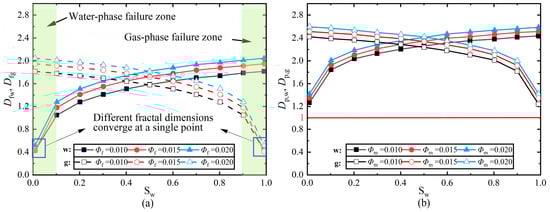
Figure 2.
The phase fractal dimensions versus saturation: (a) Fractal dimensions of gas and water phases under different pore conditions in fracture networks; (b) Fractal dimensions of gas and water phases under different porosity conditions in rock matrices. Where Df,w and Df,g are the fractal dimensions of the water phase and gas phase in the fracture network, respectively, Dp,w and Dp,g are the fractal dimensions of the water phase and gas phase in the fracture matrix, respectively.
As shown in the figure above, the water/gas pore subnetwork no longer exhibits linear structures but instead becomes branched and partially fills the area, forming a more spatially compact connected set. This geometric transformation explains why the two-phase window narrows as the system approaches single-phase conditions. Figure 2a shows the phase-related fractal descriptors increasing from low saturation and then stabilizing, with higher fracture porosity leading to consistently larger values. In the figure, there are two regions of fractal dimension failure at the saturation extremes. Within these edge ranges, the geometric fractal dimension of the fracture network cannot reflect the expected network scale structure (near the two ends, the system approaches the single-phase condition). Our discussion focuses on the central range, where this descriptor is meaningful for explaining the relative permeability behavior. Figure 2b exhibits a similar monotonic trend for porosity-related descriptors. It shows that the fractal dimension related to the gas/water porosity always exceeds 1, indicating that the structure is fully developed to support the flow of gas and water. These patterns indicate that structure-controlled pathways strengthen from low to intermediate saturation, consistent with the later dominance of network-scale descriptors for the relative-permeability curves.
The gas-water relative permeability curves were constructed from Equations (46a) and (46b) based on the phase fractal dimensions calculated at varying saturations and the initial parameters in Table 1. A comparative evaluation with experimental observations was performed, and the resulting correspondence is displayed in Figure 3. Based on evaluation and calculation results, the dual-medium gas-water permeability expression proposed in this paper demonstrates exceptional accuracy while accounting for fracture stress sensitivity.
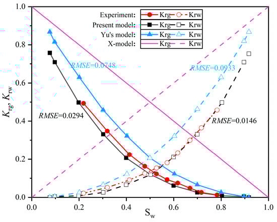
Figure 3.
Comparison of different relative permeability curves, including the present model, the experimental results, X-model and Yu’s model.
Figure 3 presents a qualitative comparison between the present model, experimental results, and Yu’s model. Gas and water relative-permeability curves are contrasted against experiments on the same saturation support. Numbers annotate quantitative agreement (RMSE). The proposed relation tracks the experiments more closely in the two-phase region and near the crossover, while maintaining comparable end-points. Yu’s model overestimates gas mobility at intermediate saturation. To ensure a corresponding quantitative evaluation, the point-to-point absolute error R(i) and global error RMSE were calculated for different models against experimental data for both Krg(Sw) and Krw(Sw). The resulting error curves are shown in Figure 4. From a quantitative perspective, the proposed model exhibits lower point-to-point errors than the reference model across all points. Significant improvements in agreement are observed in the two-phase region and near cross-saturation, while maintaining considerable accuracy at the endpoints.
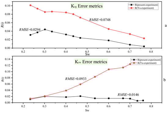
Figure 4.
Pointwise absolute errors and global RMSE of model-experiment comparisons for Krg(Sw) and Krw(Sw): (a) the pointwise absolute error versus water saturation Sw for the gas relative-permeability curve Krg(Sw); (b) the pointwise absolute error versus water saturation Sw for the water relative-permeability curve Krw(Sw).
The point-to-point absolute error R(i) and global error RMSE are derived as follows:
where ymod(i) denotes the permeability K value corresponding to the i-th Sw in the model, yexp(i) denotes the permeability K value corresponding to the i-th Sw in the experiment.
Figure 4 offers a commensurate quantitative assessment. We compute pointwise absolute errors on the experimental saturation grid and summarize the global RMSE over the full Sw range for both Krg(Sw) and Krw(Sw). From a quantitative perspective, the present model yields lower RMSE than Yu’s model for both phases. Krg: 0.0249 vs. 0.0748; Krw: 0.0146 vs. 0.0933. This indicates consistently closer agreement with the laboratory data across the saturation range.
After discussing the accuracy of this methodology, our primary focus lies in examining the effect of rock matrix and fracture network parameters on the relative permeability of gas and water. Figure 4 illustrates the effects of various values of fracture tortuosity fractal dimension (Dx), fracture fractal dimension (Df), maximum fracture radius (rf0max), and fracture porosity (ϕf) on gas-water relative permeability. Gas-water relative permeability is strongly governed by the fractal dimension of fracture tortuosity and the geometric fractal dimension of the fracture network. Specifically, when the fractal dimension of fracture tortuosity lies within 1.6–2.4, the relative permeability exhibits a non-monotonic trend—first increasing and then decreasing with water saturation—indicating that fracture-surface roughness plays a critical role in the two-phase flow regime. On the other hand, when the fracture fractal dimension changes from 2.4 to 2.8, along with an increase in water saturation, there is a weaker decline in gas phase relative permeability observed; similarly, variations in fracture porosity follow this trend as well. This suggests that the geometric fractal dimension of the fracture network and fracture porosity exert pronounced influences on fluid transport when the dual-porosity system approaches single-phase-flow conditions. By contrast, the maximum fracture radius and fractures’ porosities have only a minor impact on gas-water relative permeability.
4.2. Influence of Fracture Network Structural Parameters
After discussing the accuracy of this methodology, our primary focus lies in examining the effect of rock matrix and fracture network parameters on the relative permeability of gas and water. Figure 5 illustrates the effects of various values of fracture tortuosity fractal dimension (Dx), fracture fractal dimension (Df), maximum fracture radius (rf0max), and fracture porosity (ϕf) on gas-water relative permeability. Gas-water relative permeability is strongly governed by the fractal dimension of fracture tortuosity and the geometric fractal dimension of the fracture network. Specifically, when the fractal dimension of fracture tortuosity lies within 1.6–2.4, the relative permeability exhibits a non-monotonic trend—first increasing and then decreasing with water saturation—indicating that fracture-surface roughness plays a critical role in the two-phase flow regime. On the other hand, when the fracture fractal dimension changes from 2.4 to 2.8, along with an increase in water saturation, there is a weaker decline in gas phase relative permeability observed; similarly, variations in fracture porosity follow this trend as well. This suggests that the geometric fractal dimension of the fracture network and fracture porosity exert pronounced influences on fluid transport when the dual-porosity system approaches single-phase-flow conditions. By contrast, the maximum fracture radius and fractures’ porosities have only a minor impact on gas-water relative permeability.
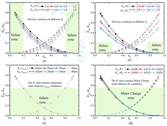
Figure 5.
Effect of fracture network parameters on the gas-water phase permeability curve: (a) fractal dimension of fracture aperture tortuosity after application of σeff; (b) fractal dimension of fracture aperture size distribution after application of σeff; (c) maximum closure radius of fractures; (d) fracture porosity.
Figure 5a,b demonstrate that fracture-network geometric fractal dimension and tortuosity-related fractal dimension reshape the curves and shift the crossover, confirming their dominant role. In contrast, Figure 5c,d vary the maximum fracture size and fracture porosity and mainly rescale end-points with limited impact on curve morphology. This contrast establishes a clear hierarchy of influence: network-scale descriptors govern shape; aperture-scale/porosity descriptors are secondary.
Regarding fracture width w, which serves as an aperture-scale parameter, varying w mainly rescales the end-point levels of K, but leaves the curve morphology essentially unchanged; by contrast, the geometric network dimension Df and the tortuosity-related dimension Dx control connectivity and path bending and dominate the curvature, crossover, and the extent of the two-phase region. Within the studied range, w is secondary to the fractal descriptors.
4.3. Influence of Rock Matrix Structural Parameters
The effects of different values of rock matrix tortuosity fractal dimension (DT), rock matrix fractal dimension (Dp), maximum matrix radius (rmax), and matrix porosity (ϕm) on the relative permeability of gas and water are illustrated in Figure 6. Among these parameters, both the rock matrix fractal dimension and matrix porosity significantly influence the gas-water phase permeability. Specifically, a slight increase in gas-water relative permeability is observed when the rock matrix fractal dimension changes from 1.2 to 2.4, while a similar increase is observed when the matrix porosity changes from 0.1 to 0.2. However, relative to the pronounced impact of fracture network parameters, variations in the rock matrix parameters contribute only marginally to the gas-water phase permeability behavior.
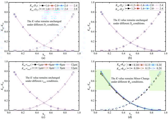
Figure 6.
Effect of the porosity matrix parameters on gas-water phase permeability curve: (a) Fractal dimension for tortuosity of matrix aperture; (b) Fractal dimension for the size distribution of matrix aperture; (c) Maximum porosity matrix radius; (d) Rock matrix porosity.
Across all figures, varying matrix-related descriptors produce minor changes, corroborating that the two-phase curve morphology is not controlled by the matrix within the studied conditions. The hierarchy observed in Figure 4 persists: fracture-network descriptors dominate, while matrix contributions remain secondary. The near-overlap of curves indicates that matrix changes primarily affect storage/transfer but do not control the relative-permeability shape in the considered range. As dual-pore systems approach single-phase conditions, fracture network characteristics—particularly the geometric fractal dimension—dominate permeability responses. In contrast, variations in maximum fracture radius and fracture porosity exert only limited influence, while perturbations in rock matrix parameters yield negligible changes in gas-water relative permeability behavior.
This study emphasizes fracture-network connectivity and tortuosity (four fractal descriptors) together with stress sensitivity, shaping gas-water relative permeability by combining the laws of Poiseuille and Cubic. We did not consider capillary pressure or non-Darcy (inertial) effects, and our study area has difficult sampling and a small number of qualified cores, which limits calibration breadth. These choices do not change our qualitative conclusion that network-scale fractal descriptors dominate the relative-permeability behavior; however, they may limit quantitative accuracy outside the present scope. Future work will incorporate capillarity and non-Darcy corrections, expand validation to other reservoir types (e.g., sandstones, shales), and build an image-constrained database of (Df and Dx) to define lithology-specific applicability windows.
5. Conclusions
This study incorporates the fractal characteristics of the aperture and phase distribution in dual-porosity media, introducing the fractal dimension of fracture surface tortuosity and examining gas-water relative permeability while accounting for stress sensitivity. The gas-water two-phase permeability model for dual medium consists of fracture tortuosity fractal dimension (Dx), fracture fractal dimension (Df), maximum fracture radius (rf0max), and fracture porosity (ϕf); rock matrix tortuosity fractal dimension (DT), rock matrix fractal dimension (Dp), maximum matrix radius (rmax) and matrix porosity (ϕm); as well as gas phase fractal dimensions in fractures and matrices (Df,g, Dp,g), water phase fractal dimensions in fractures and matrices (Df,w, Dp,w) along with water saturation (Sw). Additionally, it includes a parameter representing the fracture width degree (w). The performance of the proposed dual-medium gas-water relative permeability model is evaluated by comparing its predicted results with corresponding experimental data, demonstrating good agreement between the two. Sensitivity analysis indicates that fracture network parameters exert a more pronounced effect on the gas-water relative permeability curve than rock matrix parameters. In particular, the fractal characteristics of fracture tortuosity and fracture geometry strongly influence fluid flow as it approaches the single-phase regime in the dual-porosity medium. This paper still has some limitations: This study does not target capillary-dominated carbonate settings, and applicability in such conditions should be interpreted with caution. The stress response is represented in a linearized form, and the empirical comparison draws on a limited dataset. Future extensions will consider explicit capillary-pressure effects, nonlinear stress dependence, and broader datasets to further test and extend the framework.
The proposed dual-medium fractal model provides explicit relative permeability relationships whose shape and endpoints are governed by physically interpretable fracture descriptors: the geometric fractal dimension of the fracture network, the fractal dimension related to tortuosity, and the fracture porosity. In practical applications, these relationships can be directly utilized in three complementary ways. First, for production trend assessment, endpoint levels and crossover behavior inferred from measured fracture structures immediately provide guidance on phase mobility, waterflood progression, the gas-liquid ratio, and potential for early breakthrough. Second, for scenario screening and planning, exploring the practical ranges of the geometric fractal dimension of the fracture network, the fractal dimension related to tortuosity, and fracture porosity—constrained by core material, imaging logging, and fracture characterization studies—yields envelopes of relative permeability curves covering early, mid-term, and late-stage responses. These envelopes inform decisions regarding well location deployment, completion strategies, and flow control settings. Third, to reduce predictive ambiguity, explicit linkages between fracture descriptors and curve morphology provide a physically grounded constraint: only curve shapes consistent with independently observed fracture roughness, connectivity, and porosity distributions are accepted, narrowing the range of viable production trajectories.
Author Contributions
Conceptualization, L.Q. and Y.Y.; methodology, L.Q., Y.Y. and X.L.; software, L.Q. and Y.Y.; validation, L.Q. and Y.Y.; formal analysis, L.Q. and Y.Y.; data curation, L.Q. and X.L.; writing—original draft preparation, L.Q. and Y.Y.; writing—review and editing, X.L. and Y.S.; visualization, Y.C.; supervision, X.L.; project administration, Y.C.; funding acquisition, Y.C. All authors have read and agreed to the published version of the manuscript.
Funding
This work was supported by the CNPC Innovation Found (2022DQ02-0202), supported by Shaanxi Provincial Natural Science Basic Research Program (2024JC-YBQN-0397) and National Key Research and Development Program of China: Efficient Development Technology for Fractured-Porous Carbonate Gas Reservoirs (2025ZD1406406).
Data Availability Statement
Dataset available on request from the authors.
Conflicts of Interest
The authors declare no conflicts of interest.
Nomenclature
| θ | Fracture plane dip concerning flow direction in the front plane |
| e | Fracture aperture |
| E | Young’s modulus |
| w | Fracture width |
| υ | Poisson’s ratio |
| N | The cumulative number of fractures or porosity matrix |
| Δp | The differential pressure |
| ϕm | Rock matrix porosity |
| ϕf | Fracture network porosity |
| rmin | Minimum porosity matrix radius |
| rmax | Maximum porosity matrix radius |
| rfmin | Minimum fracture radius |
| rfmax | Maximum fracture radius |
| rf0min | Minimum closure fracture radius |
| rf0max | Maximum closure fracture radius |
| σeff | Effective stress on fracture surface |
| L0 | Length of the model |
| Ltf | The tortuous length of fracture |
| Lt | The tortuous length of a capillary |
| DT | Fractal dimension for tortuosity of matrix radius |
| DP | Fractal dimension for the distribution of matrix radius |
| Dx | Fractal dimension for tortuosity of fracture radius after σeff is applied |
| Df | Fractal dimension for the distribution of fracture radius after σeff is applied |
| Df,i | The phase fractal dimension of fracture radius distribution |
| DP,i | The phase fractal dimension of matrix radius distribution |
| Kf | The permeability of fracture network |
| Kt | The equivalent permeability of dual-porosity media |
| Kt,w | Dual medium water phase effective permeability |
| Kt,g | Dual medium gas phase effective permeability |
| Krw | Water phase relative permeability of dual medium |
| Krg | Gas phase relative permeability of dual medium |
| dE | Euclidean dimension |
References
- Xiang, Z.; Zhen, R.; Xu, Y.; Wang, S.; Ao, X.; Chen, Z.; Hu, J. A numerical pressure transient model of fractured well with complex fractures of tight gas reservoirs considering gas-water two phase by EDFM. Geoenergy Sci. Eng. 2023, 231, 212286. [Google Scholar] [CrossRef]
- Lv, M.; Xue, B.; Guo, W.; Li, J.; Guan, B. Novel calculation method to predict gas-water two-phase production for the fractured tight-gas horizontal well. J. Pet. Explor. Prod. Technol. 2024, 14, 255–269. [Google Scholar] [CrossRef]
- Tan, M.; Su, M.; Liu, W.; Song, X.; Wang, S. Digital core construction of fractured carbonate rocks and pore-scale analysis of acoustic properties. J. Pet. Sci. Eng. 2021, 196, 107771. [Google Scholar] [CrossRef]
- Yu, B.; Li, J.; Li, Z.; Zou, M. Permeabilities of unsaturated fractal porous media. Int. J. Multiph. Flow 2003, 29, 1625–1642. [Google Scholar] [CrossRef]
- Song, W.; Yao, J.; Li, Y.; Sun, H.; Wang, D.; Yan, X. Gas-Water Relative Permeabilities Fractal Model in Dual-Wettability Multiscale Shale Porous Media During Injected Water Spontaneous Imbibition and Flow Back Process. Fractals 2020, 28, 2050103. [Google Scholar] [CrossRef]
- Eparu, C.N.; Prundurel, A.P.; Doukeh, R.; Stoica, D.B.; Ghețiu, I.V.; Suditu, S.; Stan, I.G.; Rădulescu, R. Optimizing Underground Natural Gas Storage Capacity through Numerical Modeling and Strategic Well Placement. Processes 2024, 12, 2136. [Google Scholar] [CrossRef]
- Matthäi, S.K.; Mezentsev, A.; Belayneh, M. Finite Element-Node-Centered Finite-Volume Two-Phase-Flow Experiments with Fractured Rock Represented by Unstructured Hybrid-Element Meshes. SPE Reserv. Eval. Eng. 2007, 10, 740–756. [Google Scholar] [CrossRef]
- Zhang, Q.; Wu, X.; Meng, Q.; Wang, Y.; Cai, J. Fractal Models for Gas-Water Transport in Shale Porous Media Considering Wetting Characteristics. Fractals 2020, 28, 2050138. [Google Scholar] [CrossRef]
- Lu, C.; Qin, X.; Yu, L.; Geng, L.; Mao, W.; Bian, H.; Meng, F. The Characteristics of Gas-Water Two-Phase Radial Flow in Clay-Silt Sediment and Effects on Hydrate Production. Geofluids 2021, 2021, 6623802. [Google Scholar] [CrossRef]
- Zeng, Y.; Bian, X.; Wang, L.; Zhang, L. Coupling model of gas-water two-phase productivity calculation for fractured horizontal wells in tight gas reservoirs. Geoenergy Sci. Eng. 2024, 234, 212666. [Google Scholar] [CrossRef]
- Yang, M.; Mousavi, S.M.; Fatehi, H.; Bai, X.-S. Numerical simulation of biomass gasification in fluidized bed gasifiers. Fuel 2023, 337, 127104. [Google Scholar] [CrossRef]
- Wang, K.; Jiang, B.; Ye, K.; Li, H.; Tan, Y. Spontaneous imbibition model for micro-nano-scale pores in shale gas reservoirs considering gas-water interaction. J. Pet. Sci. Eng. 2022, 209, 109893. [Google Scholar] [CrossRef]
- Cai, M.; Elsworth, D.; Su, Y.; Lu, M. A New Fractal Temporal Conductivity Model for Propped Fracture and Its Application in Tight Reservoirs. Fractals 2020, 28, 2050074. [Google Scholar] [CrossRef]
- Lei, G.; Qu, J.; Wu, Q.; Pang, J.; Su, D.; Guan, J.; Lu, C. Theoretical analysis of threshold pressure in tight porous media under stress. Phys. Fluids 2023, 35, 73313. [Google Scholar] [CrossRef]
- Luo, X.; Cheng, Y.; Tan, C. Calculation method of equivalent permeability of dual-porosity media considering fractal characteristics and fracture stress sensitivity. J. Pet. Explor. Prod. Technol. 2023, 13, 1691–1701. [Google Scholar] [CrossRef]
- Wang, L.; Yang, S.; Peng, X.; Deng, H.; Meng, Z.; Qian, K.; Wang, Z.; Lei, H. An improved visual investigation on gas-water flow characteristics and trapped gas formation mechanism of fracture-cavity carbonate gas reservoir. J. Nat. Gas. Sci. Eng. 2018, 49, 213–226. [Google Scholar] [CrossRef]
- Li, C.; Xia, Z.; Wang, P. Seepage characteristics of tight sandstone gas reservoir in main gas production stage. Spec. Oil Gas. Reserv. 2016, 23, 94–96. [Google Scholar] [CrossRef]
- Ali, A.A.; Abdul-Majeed, G.H.; Al-Sarkhi, A. Review of Multiphase Flow Models in the Petroleum Engineering: Classifications, Simulator Types, and Applications. Arab. J. Sci. Eng. 2025, 50, 4413–4456. [Google Scholar] [CrossRef]
- Ren, X.; Li, A.; Memon, A. Experimental Study on Gas-Water Relative Permeability Characteristics of Tight Sandstone Reservoir in Ordos Basin. Geofluids 2022, 2022, 1521837. [Google Scholar] [CrossRef]
- Shen, J.; Qin, Y.; Li, Y.; Wang, G. Experimental investigation into the relative permeability of gas and water in low-rank coal. J. Pet. Sci. Eng. 2019, 175, 303–316. [Google Scholar] [CrossRef]
- Miao, T.; Chen, A.; Xu, Y.; Cheng, S.; Wang, K. A Permeability Model for Water-gas Phase Flow in Fractal Fracture Networks. Fractals 2018, 26, 1850087. [Google Scholar] [CrossRef]
- Wang, X.; Sheng, J.J. Multi-scaled pore network modeling of gas-water flow in shale formations. J. Pet. Sci. Eng. 2019, 177, 899–908. [Google Scholar] [CrossRef]
- Guo, C.; Sun, J.; Liu, H. Transport Model for Gas and Water in Nanopores of Shale Gas Reservoirs. J. Energy Eng. 2021, 147, 4021022. [Google Scholar] [CrossRef]
- Xia, B.; Luo, Y.; Pan, C.; Gong, T.; Hu, H.; Ji, K. Coalbed methane flow characteristics based on fractal geometry and stochastic rough fracture network. Energy Sources Part. A-Recovery Util. Environ. Eff. 2021, 47, 3877–3895. [Google Scholar] [CrossRef]
- Zhang, X.; Ma, F.; Dai, Z.; Wang, J.; Chen, L.; Ling, H.; Soltanian, R. Radionuclide Transport in Multi-scale Fractured Rocks: A Review. J. Hazard. Mater. 2021, 424, 127550. [Google Scholar] [CrossRef] [PubMed]
- Xiao, Q.; Wang, H.; Yang, Y.; Li, Z.; Jiang, B.; Li, J.; Xiang, Z. Triple-Porosity and Dual-Permeability Productivity Prediction Model of CBM Wells Considering Complex Flow Regimes. Front. Earth Sci. 2022, 10, 906276. [Google Scholar] [CrossRef]
- Zhao, M.; Kong, D.; Teng, S.; Shi, J. Combined effects of the roughness, aperture, and fractal features on the equivalent permeability and nonlinear flow behavior of rock fracture networks. Phys. Fluids 2024, 36, 74110. [Google Scholar] [CrossRef]
- Xue, K.; Zhang, Z.; Han, X.; Guang, W. A fractal model for estimating the permeability of tortuous fracture networks with correlated fracture length and aperture. Phys. Fluids 2023, 35, 43615. [Google Scholar] [CrossRef]
- Shi, D.; Li, L.; Guo, Y.; Liu, J.; Tang, J.; Chang, X.; Song, R.; Wu, M. Estimation of rough fracture network permeability using fractal and topology theories. Gas. Sci. Eng. 2023, 116, 205043. [Google Scholar] [CrossRef]
- Kong, D.; Zhao, M.; Teng, S.; Shi, J. Stress-Dependent Fractal Model for Predicting the Relative Permeability of Rocks Based on Equivalent Capillaries. Ind. Eng. Chem. Res. 2023, 62, 22071–22080. [Google Scholar] [CrossRef]
- Ferreira, C.A.S.; Nick, H.M. On the influence of matrix flow in the hydraulic permeability of rough-walled fractures. J. Hydrol. 2024, 645, 132192. [Google Scholar] [CrossRef]
- Meng, S.; Zeng, Y.; Wu, Q. Unraveling the mechanisms of dual-permeability flow in weakly cemented sandstones: An in-depth exploration of matrix-fracture interactions. J. Hydrol. 2025, 661, 133731. [Google Scholar] [CrossRef]
- Dai, P. Experiment and Numerical Simulation of Low Permeability Stress Sensitive Reservoir. Southwest Petroleum University: Chengdu, MA, China, 2006.
- Feng, Y.; Liu, Y.; Lei, G. Study on Stress-Dependent Permeability of Fracture Networks in Fractured Porous Media. Geofluids 2021, 2021, 7433547. [Google Scholar] [CrossRef]
- Chen, Z.; Ewing, R. Mathematical Analysis for Reservoir Models. SIAM J. Math. Anal. 1999, 30, 431–453. [Google Scholar] [CrossRef]
- Liu, R.; Li, B.; Jiang, Y.; Jing, H.; Yu, L. Relationship between equivalent permeability and fractal dimension of dual-porosity media subjected to fluid-rock reaction under triaxial stresses. Fractals 2018, 26, 1850072. [Google Scholar] [CrossRef]
- You, X.; Liu, J.; Jia, C.; Li, J.; Liao, X.; Zheng, A. Production data analysis of shale gas using fractal model and fuzzy theory: Evaluating fracturing heterogeneity. Appl. Energy 2019, 250, 1246–1259. [Google Scholar] [CrossRef]
- Hu, B.; Wang, J.; Ma, Z. A Fractal Discrete Fracture Network Based Model for Gas Production from Fractured Shale Reservoirs. Energies 2020, 13, 1857. [Google Scholar] [CrossRef]
- Liang, X.; Hou, P.; Xue, Y.I.; Yang, X.; Gao, F.; Liu, J. A Fractal Perspective on Fracture Initiation and Propagation of Reservoir Rocks Under Water and Nitrogen Fracturing. Fractals 2021, 29, 2150189. [Google Scholar] [CrossRef]
- Chen, H.; Feng, S. Evaluation and Application of Fractal-Based Hydraulic Constitutive Model for Unsaturated Flow in Heterogeneous Soils. Comput. Geotech. 2023, 159, 105497. [Google Scholar] [CrossRef]
- Jafari, A. Permeability Estimation of Fracture Networks. Ph.D. Thesis, University of Alberta, Edmonton, AB, Canada, 2011. [Google Scholar] [CrossRef]
- Xu, P.; Li, C.; Qiu, S.; Sasmito, A.P. A Fractal Network Model for Fractured Porous Media. Fractals 2016, 24, 1650018. [Google Scholar] [CrossRef]
- Hu, B.; Wang, J.G.; Wu, D.I.; Wang, H. Impacts of Zone Fractal Properties on Shale Gas Productivity of a Multiple Fractured Horizontal Well. Fractals 2018, 27, 1950006. [Google Scholar] [CrossRef]
- Luo, Y.; Sun, Y.; Li, L.; Wang, X.; Qin, C.; Liu, L.; Liu, C.; Wu, D. Image-based pore-network modeling of two-phase flow in hydrate-bearing porous media. Energy 2022, 252, 124044. [Google Scholar] [CrossRef]
- Gu, K.; Ning, Z. Fractal dimension changes of shale pore structure and influence on mechanical properties, relative permeability under different hydration degree. Environ. Earth Sci. 2023, 82, 189. [Google Scholar] [CrossRef]
- Gere, J.M.; Goodno, B.J. Mechanics of Materials; Cengage Learning: Boston, MA, USA, 2012. [Google Scholar]
Disclaimer/Publisher’s Note: The statements, opinions and data contained in all publications are solely those of the individual author(s) and contributor(s) and not of MDPI and/or the editor(s). MDPI and/or the editor(s) disclaim responsibility for any injury to people or property resulting from any ideas, methods, instructions or products referred to in the content. |
© 2025 by the authors. Licensee MDPI, Basel, Switzerland. This article is an open access article distributed under the terms and conditions of the Creative Commons Attribution (CC BY) license (https://creativecommons.org/licenses/by/4.0/).