1. Introduction
Heat transfer is a fundamental phenomenon in numerous practical applications of energy conversion, transfer, and utilization. Heat exchangers, with various design solutions, capacities, working fluids, and functional specificities, have broad applications in industries such as steam power plants, chemical and pharmaceutical processing, food production, transportation power systems, refrigeration units, heating, and air conditioning, as well as in other areas, including non-industrial sectors such as high-efficiency medical equipment. The use of new technologies and materials is aimed at enhancing the efficiency and performance of heat exchangers.
The calculation and design of heat exchange systems are linked to the solution of highly complex problems related to heat transfer and the transmission of high-density and high-intensity heat fluxes. Heat exchange devices often employ elements that increase the heat transfer surface, such as fins, ribs, and lamellae, among others. In most cases, it is necessary to apply optimization approaches to determine the optimal parameters of the finned system in order to achieve the required heat fluxes with fin elements of optimal dimensions and minimal volume. This approach helps minimize material consumption during the production of well-profiled finned heat transfer surfaces while ensuring that devices are compact and efficient.
Beyond the geometric optimization, the fluid flow (for instance, air flow) around the finned system results in complex conditions for heat exchange between the finned surface and its surroundings. Therefore, it is crucial to conduct research that combines analytical and numerical methods, focusing on convective heat transfer mechanisms, to improve the efficiency of heat exchange between different surface types and the environment.
Substantial improvements in energy efficiency across various industrial applications can be achieved through the use of more effective heat transfer surfaces. Sahiti (2015) [
1] demonstrated that the optimization of fin geometry, particularly the length of pin fins, has a significant impact on the thermal performance of heat exchangers. Kraus, Aziz, and Welty (2001) [
2] provide a comprehensive overview of extended surface heat transfer, focusing on the optimization of finned surfaces with diverse geometries such as rectangular, triangular, and trapezoidal profiles. Pardeep et al. (2019) [
3] conducted a comprehensive analysis on the influence of fin extensions in heat transfer systems, demonstrating that extending the surface area substantially improves thermal dissipation. This study further emphasizes the pivotal role of material thermal conductivity, geometric configuration, and ambient conditions in determining overall thermal efficiency. Sobamowo (2017) [
4] conducted an analytical investigation of the dimensionless temperature distribution in rectangular fins as a function of dimensionless length, considering various values of thermo-geometrical parameters and internal heat generation. Toner and Kılıç (1983) [
5] carried out a comparative analysis of the thermal performance of rectangular and triangular fins under both condensation and non-condensation conditions and determined the optimal fin dimensions as a function of the Biot number. Aziz (1994) [
6] presented a detailed optimization analysis aimed at determining the optimal dimensions of straight fins, annular fins, and spines with various geometric profiles. Arslanturk (2005) [
7] conducted a one-dimensional analysis and optimization study of annular fins with uniform thickness, focusing on the determination of their optimal geometric configuration. Lindstedt and Kaj (2004) [
8] analyzed the thermal performance of rectangular, triangular, and trapezoidal fins using both analytical and numerical methods, offering a comparative evaluation of the results. Bunjaku et al. (2023) [
9] proposed a methodology for optimizing the thermal performance of different fin geometries, such as rectangular and triangular profiles, while also incorporating the effects of various fin materials.
Building upon these insights into geometric optimization, several studies have additionally investigated the effects of operating conditions and convective mechanisms on fin performance. Kundu and Das (2002) [
10] investigated the performance and optimization of straight taper fins under conditions of variable convective heat transfer, considering a linear variation of the heat transfer coefficient along the fin surface. Lee et al. (2016) [
11] conducted an experimental investigation on natural convection from vertical cylinders equipped with inclined plate fins, demonstrating that variations in fin inclination angle, number of fins, and base temperature have a significant influence on the thermal resistance and overall cooling performance. Furthermore, Lee et al. (2017) [
12] performed a thermal optimization study on horizontal tubes with tilted rectangular fins, emphasizing the crucial role of fin geometry and orientation in enhancing heat transfer rates and minimizing thermal resistance under free convection conditions. Bunjaku and Filkoski (2023) [
13] performed an optimization of thermal and geometric parameters of cylindrical fins under natural convection conditions, demonstrating that fin performance can be significantly improved through careful selection of dimensions and material properties. Hameed et al. (2020) [
14] investigated various fin geometries under natural convection and confirmed that fin shape strongly governs the thermal performance of heat sinks. Hussein et al. (2022) [
15] examined different fin configurations under natural convection and demonstrated that fin geometry is a decisive parameter, with efficiencies consistently above 90%, thereby confirming the strong influence of geometry on overall thermal performance and optimization. Obaid and Hameed (2023) [
16] conducted an experimental and numerical investigation under mixed convective conditions and reported that novel fin configurations can substantially enhance the thermal performance of heat sinks, further emphasizing the role of fin geometry in improving heat dissipation efficiency.
More recently, attention has turned toward innovative fin geometries, advanced manufacturing techniques, and novel design strategies aimed at further enhancing thermal performance. Kim (2021) [
17] compared various optimized finned annuli with different fin shapes. This study concluded that the finned annuli with variable fin thickness exhibited the best performance compared to the fins of other shapes. A numerical comparison of thermal performances of various design models of rectangular fins having holes has been presented by Meganathan et al. [
18]. The authors reported that the rectangular fin having holes provides high heat transfer. Kirincic et al. (2021) [
19] conducted a numerical analysis of a shell-and-tube thermal energy storage system incorporating longitudinal fins, based on latent heat utilization. Najim et al. (2022) [
20] further compared triangular and rectangular fins in a vertical triple-tube PCM storage system, showing that fin geometry has a decisive impact on natural convection performance. Adhikari et al. (2020) [
21] conducted a numerical and experimental study on a heat sink design for natural convection cooling of LED grow lights and showed that fin geometry significantly affects thermal performance. Unger (2021) [
22] analyzed additively manufactured finned heat exchanger configurations, demonstrating that innovative fin designs can further enhance natural convection efficiency. Krıshnayatra et al. (2022) [
23] conducted a parametric numerical study on finned-tube systems, showing the effects of fin geometry, number, and orientation on natural convection performance. Altun and Ziylan (2019) [
24] showed that sinusoidal wavy fins under natural convection enhance heat transfer compared to rectangular fins. Similarly, Andrew and Oyejide (2018) [
25] reported that triangular fins with perforations provide higher heat dissipation in natural convection.
Building on the insights provided by previous studies, this work develops a mathematical model based on Bessel’s differential equations to optimize ribbed or profiled heat transfer surfaces. Analytical solutions are obtained for key parameters, including fin efficiency, dimensionless temperature, and optimal geometry. The results are compared with CFD simulations for rectangular and triangular fins attached to cylindrical tubes under identical cross-sectional area and volume conditions. The primary objective is to determine the optimal fin configuration that maximizes heat transfer with minimal material usage, thereby providing practical guidelines for the design of efficient and cost-effective heat exchangers.
2. Materials and Methods
The use of finned systems such as finned heat exchangers, finned tubes, or other fin-integrated components is primarily intended to enhance heat transfer performance. These systems are particularly effective in applications involving fluids with significantly different convective heat transfer coefficients on either side of a thermal boundary. In such cases, the disparity in heat transfer rates can be partially offset by increasing the surface area through the use of fins or similar surface extensions. In practical applications, the ratio of non-finned to finned surface area typically ranges from 1:10 to 1:50, or even higher. Overall, the integration of ribbed or finned surfaces across various industrial processes enhances heat exchange effectiveness and system efficiency by maximizing the available surface area, thereby contributing to greater energy efficiency, lower operational costs, and improved system performance.
Depending on the application, fins are designed and manufactured in many shapes and forms. The most commonly used extended surfaces include straight fins with rectangular or trapezoidal profiles, annular fins with rectangular or triangular cross-sections, and pin fins of cylindrical or conical shape.
These geometries are implemented across a wide range of engineering systems, each with specific operational requirements and design constraints. This applies to a wide range of components used in heating, ventilation, and air conditioning (HVAC) systems, as well as in thermal processing units within manufacturing industries. It also includes applications such as air-cooled housings for electric motors, cooling systems for electronic equipment (e.g., data centers and personal computers), specialized heat exchangers, and solar thermal water-heating systems.
To ensure analytical tractability and consistency with classical fin theory, the assumptions and constraints imposed to define and bound the problem are essential for simplifying the governing equations and enhancing the accuracy of solutions related to fin geometry analysis. Contemporary studies on fin configurations are largely grounded in the foundational works of Murray (1938) and Gardner (1945). These simplifications, commonly known as the Murray–Gardner assumptions, are thoroughly discussed in the work of Kraus et al. (2001) [
2]. In the present study, these assumptions are directly applied to the analytical modeling, namely steady-state heat transfer in a homogeneous fin material with constant thermal conductivity, uniform base temperature with perfect thermal contact, constant convective coefficient, and negligible effects of thickness gradients, edge losses, and tip heat transfer. These applied assumptions provide a consistent and simplified framework for evaluating the thermal performance of the fin geometries.
2.1. Rectangular Fin Elements
Basic or primary surfaces and their associated extension elements are collectively referred to as extended surfaces, as opposed to bare surfaces without any attachments. These extension elements may consist of fins, ribs, sheets, lamellae, or other geometric modifications designed to increase the surface area available for heat transfer. A key challenge in the design of efficient heat exchangers lies in the development of methods for heat transfer enhancement, which is critical for achieving optimal device performance. Consequently, the analysis of various fin profiles is essential to identify correlations between geometric parameters and heat transfer intensity.
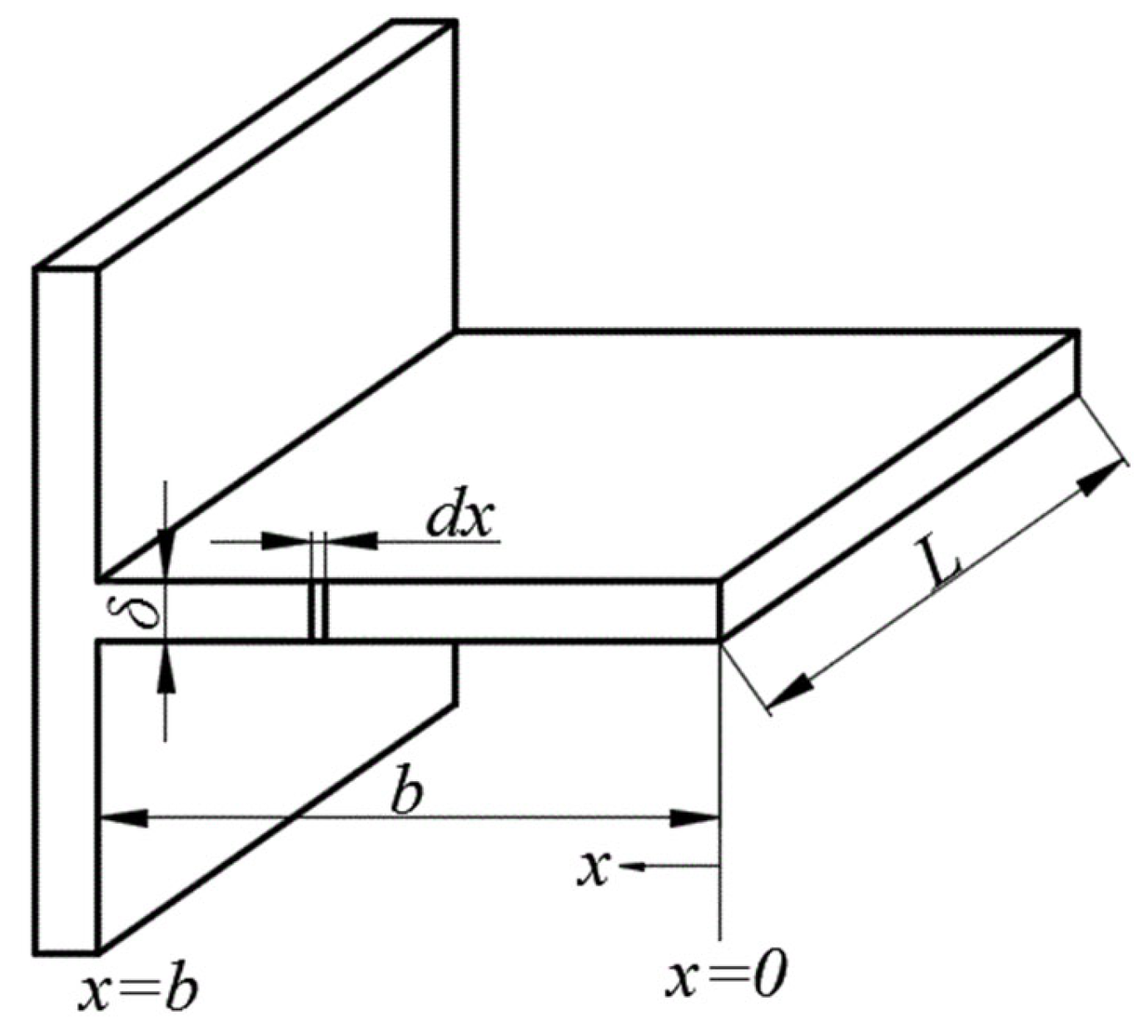
To illustrate these relationships and to establish the fundamental heat transfer behavior of extended surfaces, a typical fin with a rectangular profile is illustrated in
Figure 1. Heat transfer through the fin is governed by the following general form of the differential equation, which characterizes the thermal behavior of extended surfaces:
where
θ = T − Tfluid is the temperature difference between the temperature of the fins’ surface (T) and the temperature of the surrounding air (Tfluid).
is a characteristic parameter.
h is the heat transfer coefficient.
k is the thermal conductivity of the fin material.
Figure 1.
The profile of rectangular fin.
Figure 1.
The profile of rectangular fin.
The boundary conditions applied in this model are given below:
where
θb is the temperature difference at the base of the fin, and
h2 and
θtip correspond to the heat transfer coefficient and the temperature difference at the top of the fin.
By considering the boundary conditions in Equation (2) and receipt
h2 = 0 to simplify the problem (i.e., neglecting the thermal flux at the tip of the fin), the solution to Equation (1), based on the work of Kraus et al. [
2], is obtained in the following form:
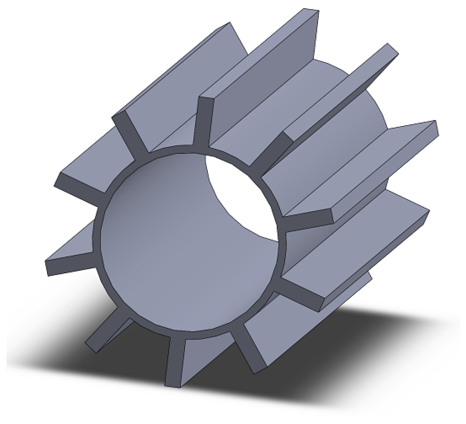
In this configuration, the design features a cylindrical tube equipped with rectangular fins mounted on its outer surface (
Figure 2). The addition of these fins increases the effective surface area of the tube, thereby enhancing the heat transfer capacity between the two working fluids.
The analysis is carried out for the tube with rectangular fins with thickness δ and the fin height b, while the fin’s length will be marked with L. For the adopted analyzed model, the surface of the fin’s transverse cut is taken as a constant value (Sr = δb = const). The model for Sr = const is essential concerning increasing the efficiency of the finned system.
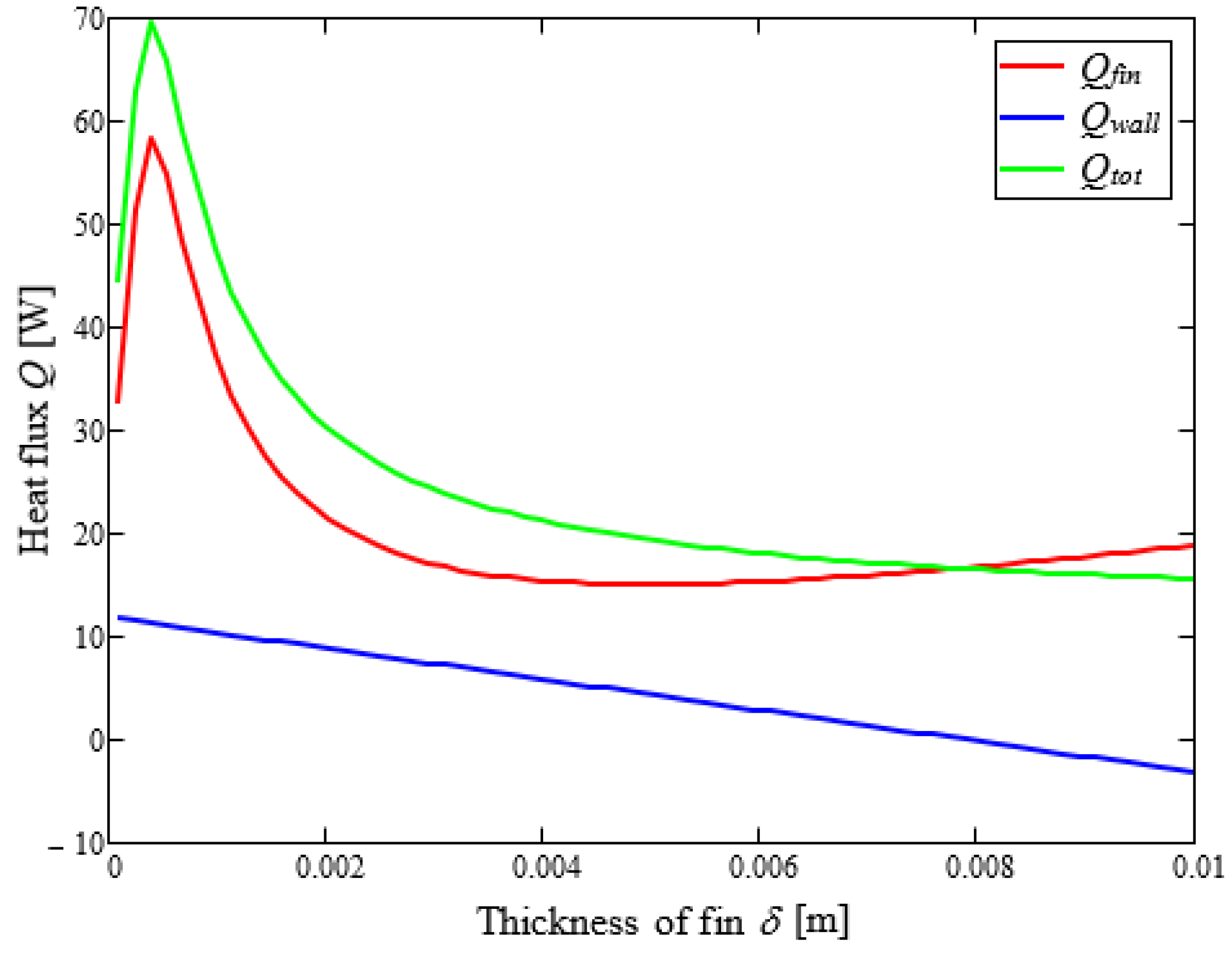
The heat flux from the tube-finned surface for the 10 rectangular fins is given with the expression:
The heat flux from the non-finned surface, which is situated at the side of the finned system, is expressed as:
The overall heat flux is:
2.2. Triangular Fin Elements
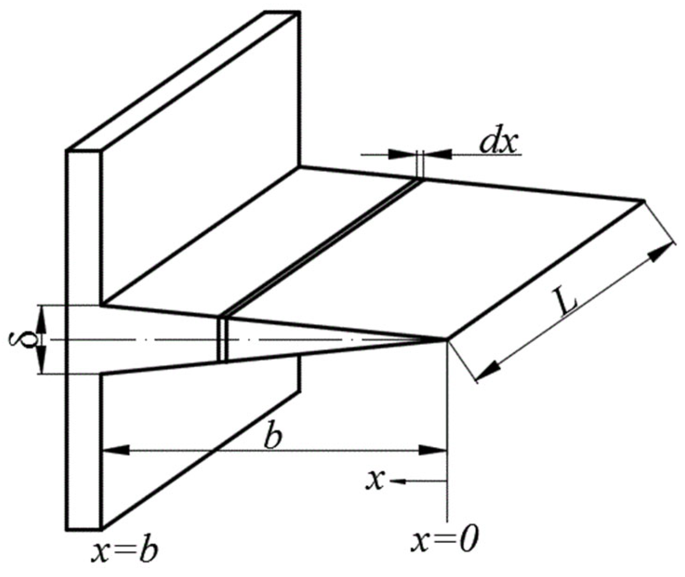
In the case of triangular fins, the analysis involves a variable fin profile, as illustrated in
Figure 3. In this model, the variation of the temperature gradient along the transverse (orthogonal) direction is neglected, and thus a one-dimensional temperature distribution is assumed for the fin.
The following differential equation characterizes the heat transfer process in triangular fins:
where the characteristic fin parameter
m is defined as presented in Kraus et al. [
2], and
b denotes the height of the fin.
The boundary conditions applicable to this model are as follows:
Equation (8) is a modified Bessel differential equation, and its solution, based on the work of Kraus et al. [
2], is given by:
The heat flux through a triangular fin can be expressed as:
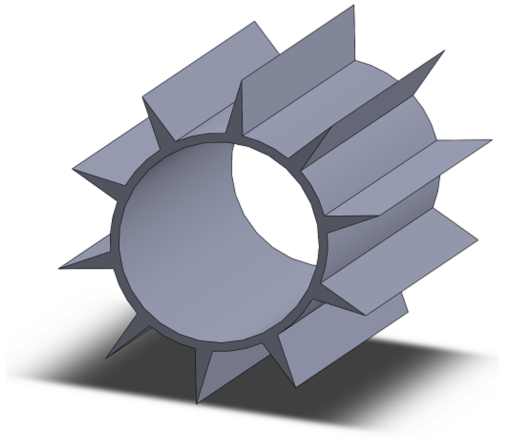
Similar to the case of the rectangular finned tube, the modeling approach for the triangular finned tube—characterized by fin thickness
δ, fin height
b, and fin length
L—is presented below, as shown in
Figure 4.
The heat flux through the fins and the tube wall is given by the following expressions:
The total heat flux is defined by the following relation:
2.3. Numerical Method
2.3.1. Governing Equations
The governing equations consist of the continuity equation, the momentum equations, and the energy equation for the fluid, together with the heat-conduction equation in the solid. They are expressed in Cartesian coordinates (x, y, z). The following equations are solved:
Continuity equation for the steady flow:
2.3.2. Modeling Approach and Assumptions
In the present study, the flow is modeled as laminar, steady, and incompressible, which is justified by the relatively low Reynolds number conditions of the analyzed cases. As a result, no turbulence models or additional transport equations are required, and the governing equations reduce to the standard continuity, momentum, and energy equations presented above. Thermophysical properties are assumed to be constant, radiation and multiphase effects are neglected, and heat transfer from the fin tip is not considered. Gravity effects are included as the driving force for natural convection. These assumptions form the theoretical basis of the CFD model.
These governing equations form the theoretical foundation of the model, and their numerical solution is carried out in ANSYS Fluent 16.2, as described in the following subsection.
2.3.3. Numerical Implementation in ANSYS Fluent
Advanced modeling techniques, such as computational fluid dynamics (CFD), employ numerical simulations to analyze fluid flow and heat transfer phenomena. For several decades, CFD has been extensively used in engineering and scientific research to investigate and predict the behavior of fluids, thermal systems, and their interactions with solid surfaces. In the context of numerical methods, several case studies involving different thermal systems modeled using CFD are presented in [
9,
12]. In particular, ref. [
9] examines rectangular and triangular fins, addressing challenges closely related to those investigated in the present study.
Numerical calculations were performed using ANSYS Fluent 16.2 software, based on the finite volume method with a structured mesh and second-order discretization schemes to ensure accuracy and minimize numerical errors. In addition, the Least Squares Cell Based method was used for gradient evaluation, with second-order schemes for pressure, momentum, and energy to minimize numerical diffusion. The transient, three-dimensional phase-change problem was solved numerically within this framework. For the current computational model, a structured grid was generated, consisting of approximately 6930 to 8500 volume cells and 11,264 to 16,524 nodes for tubes with rectangular fins. For tubes with triangular fins, the mesh comprised 4914 to 8575 volume cells and 8192 to 15,850 nodes. A preliminary mesh sensitivity analysis was conducted using grids of varying densities. The selected mesh was found to be optimal in terms of quality and offered a reasonable compromise between computational cost and accuracy, ensuring solution independence with respect to mesh size.
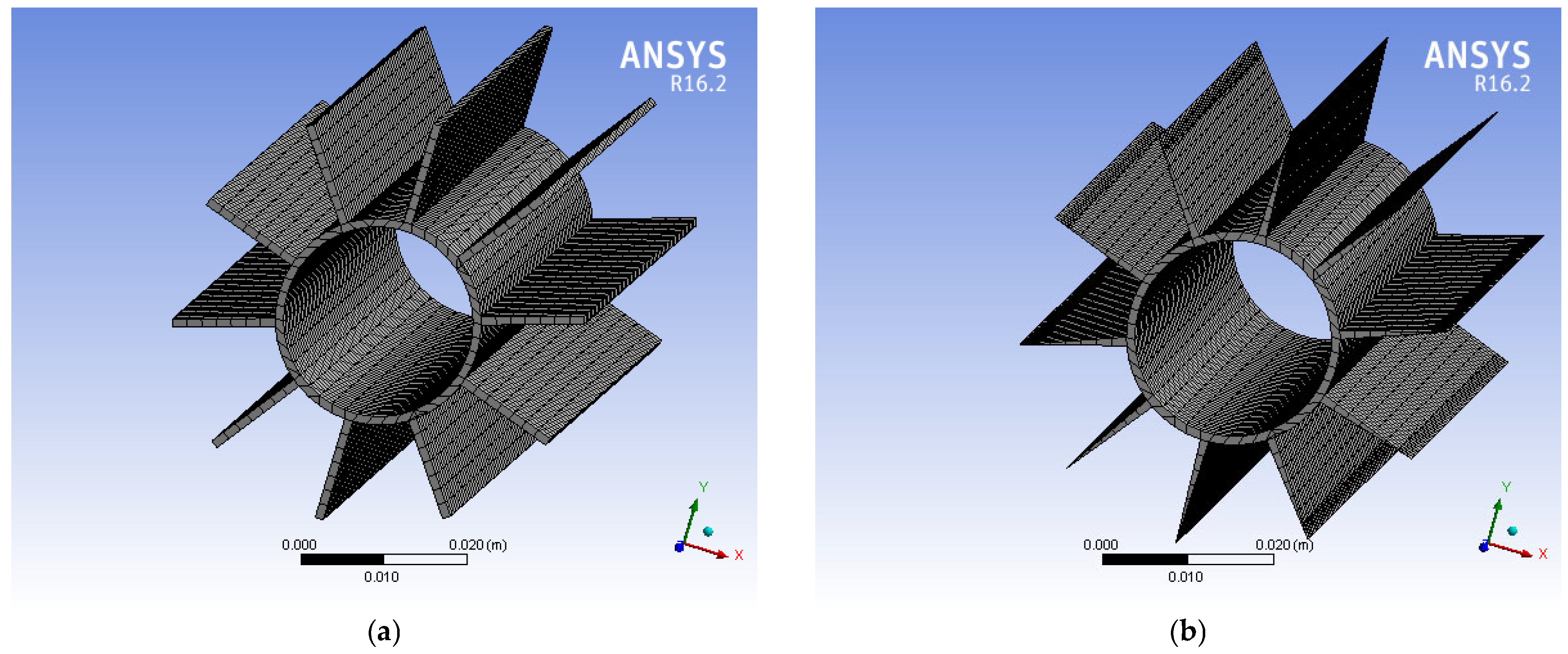
A structured mesh was employed for all cases, with local refinement near the tube–fin interfaces where the highest thermal gradients occur, in order to adequately resolve the flow and temperature fields while keeping the computational effort within reasonable limits, as shown in
Figure 5.
To verify the adequacy of this discretization, a mesh independence study was carried out for both rectangular and triangular fin configurations. The results, summarized in
Table 1, indicate that further mesh refinement produced negligible variations in the temperature distribution. This demonstrates that the adopted mesh resolution provides sufficient accuracy while maintaining computational efficiency.
In the present study, the geometric ranges of the models were defined by varying fin thickness between 0.5 and 4 mm and fin height between 3.13 and 25 mm for both rectangular and triangular fins while keeping the transverse cross-sectional area and total fin volume constant. The computational models were created in ANSYS Fluent 16.2 using a structured grid, and mesh sensitivity analysis was conducted to ensure independence of the solution. The applied boundary conditions included a constant base temperature of T0, a uniform ambient temperature of Tamb, and a constant convective heat transfer coefficient h applied to all fin surfaces.
For the analyzed models, the minimal convergence criterion was set to 10−6 for the continuity and momentum equation and to 10−8 for the energy equation. A mesh sensitivity analysis was conducted to minimize numerical uncertainties, while the applied steady-state assumptions further reduced potential instabilities, ensuring reliable results under the specified conditions.
To validate the computational model, the numerical results for temperature distribution and heat flux were compared with analytically derived data. The operating parameters applied in the numerical simulations are consistent with those used in the physical model. In particular, heat transfer from the fin tip is neglected in both cases.
In the CFD simulations, the outer tube surface was assigned a constant convective heat transfer coefficient, while the base temperature was fixed as uniform. Symmetry boundary conditions were imposed along the axial direction. The simulations were performed under steady-state assumptions using a laminar flow model, which is appropriate for the present study due to the low Reynolds number and the nature of the natural convection problem.
4. Conclusions
This study presented a comparative analysis of heat transfer performance in cylindrical tubes equipped with rectangular and triangular fin profiles. The analysis focused on identifying optimal fin thickness and height by maintaining constant values for both the transverse cross-sectional area and total fin volume. Specifically, for all five rectangular fin models the cross-sectional area and total volume were kept constant, whereas for the five triangular fin models these parameters were also maintained constant but were approximately half of those in the rectangular models, reflecting their geometric characteristics. Both analytical and numerical approaches, by using Computational Fluid Dynamics (CFD), were employed to evaluate thermal behavior under varying geometric configurations.
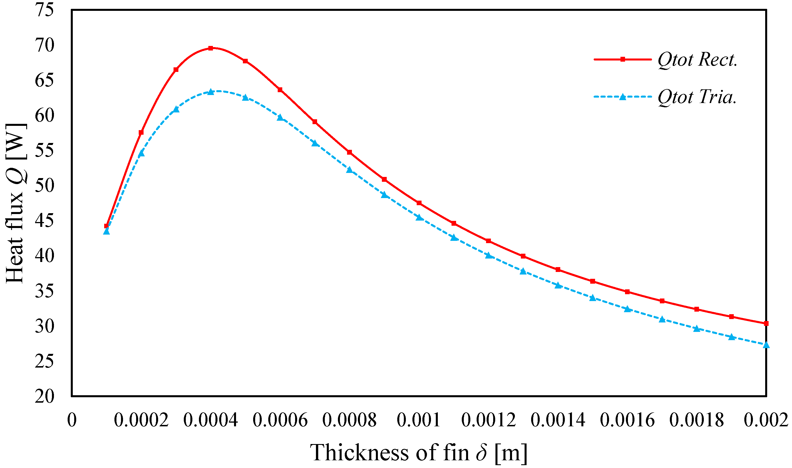
The results indicate that, for a given cross-sectional area and tube dimensions, rectangular fins provide up to 9.75% higher heat flux compared to triangular fins under optimal thickness. However, this improvement in thermal performance comes at the cost of significantly greater material usage, as the volume of rectangular fins was twice that of triangular ones. This highlights a clear trade-off, where higher thermal output is achieved at the expense of material efficiency and cost, suggesting that the practical selection of fin geometries should carefully balance thermal benefits with economic feasibility. These findings confirm that most of the heat transfer occurs near the base of the fin, where convective efficiency is highest, and that this effectiveness decreases along the fin’s extended surface.
This study demonstrates that selecting appropriate fin geometries considering both thermal performance and material volume is crucial for the optimal design of heat exchangers. The proposed methodology provides a practical framework for engineers and designers seeking to enhance heat transfer efficiency while minimizing material costs. It also reinforces the importance of balancing geometric complexity with manufacturing and operational constraints.
In particular, the main contribution of this work lies in providing a systematic comparison between rectangular and triangular fins under identical boundary and volumetric constraints and in demonstrating the trade-off between thermal enhancement and material usage. The combined analytical–numerical methodology proposed here can serve as a reliable framework for similar optimization studies.
While this analysis is based on idealized steady-state conditions and constant material properties, future research should consider transient thermal behavior, temperature-dependent conductivity, and external factors such as fin-tip convection. Moreover, experimental validation is recommended to confirm the accuracy of the numerical and analytical predictions and to further support the practical applicability of the optimized fin configurations in real-world heat exchanger systems.
Future work will also extend the current results by introducing dimensionless performance parameters, such as the Nusselt number, fin efficiency, and the overall heat transfer coefficient, in order to provide a more generalized and comparative evaluation with literature studies.
