Abstract
To address the limitations inherent in traditional simulation control schemes for dual-engine parallel operation systems in diesel engines—such as protracted development cycles, suboptimal interface compatibility, insufficient real-time performance, and inadequate support for dynamic condition simulation in applications like marine power systems—this paper proposes an embedded real-time controller based on model-based design. This methodology facilitates efficient development and high-precision real-time control of parallel operation systems. A multi-domain coupled simulation model integrating diesel power and parallel control algorithms is built in MATLAB/Simulink, with optimized C code auto-generated via Embedded Coder. Hardware centers on STM32F407VE, enabling 4–20 mA speed acquisition, CAN communication, and Ethernet transmission. Experimental results indicate that the architecture shortens development cycles from 8 to 3 weeks, with 895 microseconds of simulation steps meeting 1-millisecond real-time requirements. Vessel tests achieve ±1.8 r/min synchronization error and ±1.2% load distribution error at low cost. It adapts to varied diesel power via modular substitution and supports RS485/CAN-FD. In conclusion, the controller effectively handles real-time simulated diesel engine parallel systems and excels in efficiency, compatibility, and cost, offering a viable technical pathway for modernizing parallel power systems in applications such as marine vessels and power generation.
1. Introduction
Diesel engine parallel power systems are extensively employed in medium- to large-scale marine applications owing to their cost-effectiveness, operational reliability, and broad power range coverage [1,2]. However, such systems incorporate complex subsystems—including the diesel engine, couplings, governors, and synchronous clutches—resulting in a highly sophisticated overall architecture and demanding technical specifications. Currently, simulation training systems for such power configurations are predominantly developed using established simulation platforms, such as Mimics v.25 and Modelsim v.10.7. While these systems are capable of demonstrating fundamental operational logic, they are often hampered by substantial real-time interaction delays and limited hardware interface compatibility. These limitations contribute to elevated development costs, considerable technical hurdles, and prolonged development cycles. In domains such as intelligent vehicles and aerospace, model-based embedded simulation design has established itself as an effective methodology for controller development. The application of this approach to the design and development of diesel engine systems represents a highly promising and efficacious strategy. The PELAB laboratory proposed a model-based methodology integrating OpenModelica and MATLAB for the design of continuous linearized model predictive control systems [3,4,5,6,7,8,9,10,11,12]. Concurrently, the NASA Jet Propulsion Laboratory (JPL) employs Model-Based Systems Engineering (MBSE) approaches and SysML for the modeling and design of aerospace systems and has introduced techniques for model conversion and state analysis [13,14,15,16,17,18,19,20,21,22]. Huang applied an MBSE framework to mitigate issues such as low accuracy, poor reusability, and structural complexity in the design of conventional civil aircraft warning systems [23]. Qin adopted a model-driven design strategy to develop a dynamic target search and cooperative path planning method for unmanned underwater vehicles (UUVs), offering an effective solution for multi-UUV collaborative missions [24]. Furthermore, Wang designed and implemented an integral sliding mode control (SMC) scheme based on a reference model for multi-rotor drone speed controllers, providing a valuable reference for industrial drone applications [25].
Model-based design has demonstrated multidimensional innovation in new energy powertrains, particularly in fuel cell vehicles, offering valuable insights and references for upgrading conventional diesel engine systems. Jian conducted a study involving the development and validation of a powertrain model for fuel cell electric vehicles (FCEVs), employing hardware-in-the-loop (HIL) real-time simulation for validation [26]. Lei proposed a practical implementation strategy for reinforcement learning (RL)-based energy management strategies (EMS) in fuel cell electric vehicles (FCEVs). Their method combined the flexibility of Python v.3.12 for RL algorithms with the high-fidelity modeling capabilities of MATLAB/Simulink v.2022b, creating a robust foundation for translating simulated performance into real-world vehicle applications [27]. Sellali developed a powertrain model for a series hybrid electric tracked vehicle (SHETV). To optimize its energy management, they first designed a reinforcement learning (RL)-based algorithm, which was subsequently advanced to a deep reinforcement learning (DRL) approach [28].
Model-based design has been extensively applied and rigorously advanced across multiple engineering disciplines. This paper employs a model-based embedded simulation methodology to conduct a comprehensive investigation into the hardware and software design challenges associated with embedded simulation controllers for diesel engine parallel power systems. The study aims to offer valuable insights and practical references for subsequent research and applications in related fields. The primary objective of this research is to develop a low-cost, embedded real-time simulation controller architecture for marine applications, designed to overcome the limitations of poor interface compatibility and high latency in current simulation platforms. A further aim is to establish a model-driven software development workflow, which simplifies the creation and iteration of propulsion system simulation models, thereby reducing developmental complexity and shortening the project timeline.
2. Hardware Design of Embedded Simulation Controller for Diesel Engine Parallel Power System
- (1)
- Requirement Analysis and Design Approach
In both the actual control system and the simulation training system for diesel engine parallel power units, the accurate acquisition of key signals—such as vehicle clock signals, start commands, normal stop commands, emergency stop commands, and coupling/uncoupling status—constitutes a critical prerequisite for achieving efficient control and operational safety. The hardware design of the embedded simulation controller must, above all, guarantee the precise, reliable, and real-time acquisition and processing of these critical commands and status signals. This capability forms the foundational basis for enabling high-fidelity simulation and robust system performance.
In practical control and simulation training systems for diesel parallel power units, the accurate acquisition of vehicle clock signals, start commands, normal stop commands, emergency stop commands, and coupling/decoupling signals is a critical prerequisite for achieving efficient control and operational safety. The hardware design of the embedded simulation controller must, first and foremost, ensure the accurate, reliable, and real-time acquisition and processing of these critical commands and status signals, which serves as the foundation for high-fidelity simulation.
Firstly, as direct instructions from the operator that reflect the operational status of the diesel engine, clock signals require acquisition circuits with high precision, high reliability, and low latency to ensure the controller can respond to operational commands accurately and in real time. In addition, the acquisition circuits for start, normal stop, and emergency stop commands must feature high response speed to instantly capture these critical instructions and transmit them promptly to the controller, thereby ensuring the safety and reliability of the diesel engine under various operating conditions. Moreover, the acquisition of coupling/decoupling signals is essential for achieving precise control during the coupling process. The corresponding acquisition circuits must exhibit high noise immunity and stability to guarantee accurate signal retrieval even in complex electromagnetic environments. Furthermore, to establish a closed-loop control system and support advanced monitoring and simulation functions, real-time data—including commands, status information, and parameters—along with the computational results from simulation models, must be transmitted through highly efficient and reliable communication channels. Thus, the design of communication interfaces has become an indispensable extension of the hardware requirements.
Based on the system-level analysis of the core control requirements for the diesel engine parallel power system, the hardware design adheres to the principles of “complete signal chain, real-time processing, unified interfaces, and scalable architecture.” The main controller is structured into four functional layers: the signal acquisition and conditioning layer, the real-time computation and logic control layer, the communication and isolation layer, and the power supply and protection layer. Within this architecture, the diesel engine parallel power system model operates in real time, receiving input signals via the CAN interface from field I/O nodes, while computation results from the model are transmitted to the host computer through the Ethernet interface. Each layer is interconnected via standardized interfaces, satisfying the operational demands of an actual diesel engine control system while maintaining flexible expandability for simulation and training applications. A conceptual diagram of the design architecture is provided in Figure 1.
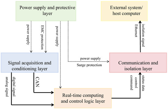
Figure 1.
Design concept flowchart.
- (2)
- MCU Core Circuit
The main control node employs the STM32F407VE microcontroller (STMicroelectronics, Geneva, Switzerland) unit (MCU), which is built around an ARM Cortex-M4 core. This processor integrates high-performance real-time processing capabilities with extensive peripheral support. Operating at a clock frequency of 168 MHz, the core delivers a scalar processing performance of up to 168 DMIPS, leveraging the high code density of the Thumb-2 instruction set and a 3-stage pipeline architecture. Notably, the inclusion of a dedicated hardware single-precision floating-point unit (FPU) substantially accelerates complex mathematical computations. Coupled with specialized digital signal processing (DSP) instruction extensions, the MCU exhibits strong performance in executing algorithms for real-time signal processing and closed-loop control applications.
The innovative Adaptive Real-Time Accelerator (ART Accelerator) technology forms its core performance advantage. This technology achieves zero-wait execution of code stored in internal flash memory through pre-fetch buffering mechanisms and instruction cache optimization, maintaining deterministic real-time response even under high clock frequency conditions. The 512 KB flash memory adopts a dual-bank architecture, supporting secure over-the-air (OTA) firmware updates during application runtime, significantly enhancing system reliability and maintainability.
The memory subsystem is meticulously designed, incorporating 192 KB of SRAM, of which 128 KB is configured as Tightly Coupled Memory (CCM RAM). The CCM is directly connected to the core via a dedicated data bus, enabling high-speed data access that bypasses the system bus matrix. This architecture provides low-latency storage essential for critical data structures and interrupt service routines in real-time applications. Furthermore, the multi-level bus architecture, built upon a Multi-AHB bus matrix, allows simultaneous parallel access by the CPU core, DMA controller, and other bus masters to different memory regions, thereby maximizing overall data throughput efficiency.
The power management unit supports operation across a wide voltage range from 1.8 V to 3.6 V and incorporates a multi-level power efficiency control mechanism, which includes low-power sleep, stop, and standby modes. Coupled with precise clock gating technology implemented in the hardware real-time clock (RCC) module, the system effectively balances performance demands with power consumption. Additionally, an integrated hardware encryption accelerator (AES) enhances data security processing capabilities. The device is offered in an LQFP144 package and is rated for industrial-grade operating temperatures from −40 °C to 85 °C. Supported by ST’s comprehensive software toolchain and hardware abstraction layer (HAL), this MCU provides a robust computational foundation for the development of high-performance real-time embedded systems.
Current embedded simulation controllers are often constrained by limited interface variety and cumbersome adaptation processes. A typical limitation is the inclusion of only one or two digital interfaces on specialized simulation boards, which necessitates additional hardware—such as analog acquisition and CAN-to-RS485 modules—to interface with standard marine signals (e.g., 4–20 mA vehicle clock signals, CAN bus speed controllers). This multi-module architecture introduces signal attenuation and latency. Furthermore, while traditional PLCs support multiple interfaces, they rely on software-based protocol conversion, consuming 30–40% of the core processing resources and resulting in poor synchronization performance.
This paper proposes a hardware architecture based on the STM32F407VE microcontroller(STMicroelectronics, Geneva, Switzerland), leveraging its rich peripheral set and hardware optimizations to deliver native multi-interface support, low adaptation cost, and high synchronization. The design utilizes three integrated 12-bit ADCs supporting 16 analog inputs, enabling direct acquisition of 4–20 mA engine speed and 0–5 V RPM sensor signals without external analog modules, with a signal acquisition error controlled within ±0.5%—four times more precise than conventional adapter-based solutions. Furthermore, the architecture incorporates two CAN controllers and an Ethernet controller, allowing direct connection to marine diesel engine governors and Ethernet monitoring terminals, thereby eliminating the need for additional CAN expansion modules. Additionally, eight high-speed GPIO pins support PWM output for direct control of clutch solenoid valves and status indicators without external driver circuits, significantly simplifying wiring and debugging.
The main controller node is primarily composed of an MCU (microcontroller) circuit, optocoupler-based isolation circuits, a CAN bus interface, RS232 and RS485 communication interfaces, an Ethernet physical layer interface, and a power supply circuit. To enhance computational performance, the node employs the STM32F407VE microcontroller, which is built upon the ARM Cortex-M4 core and incorporates a hardware floating-point unit (FPU), substantially improving processing efficiency for numerical operations. The overall circuit architecture of the main controller node is illustrated in Figure 2.
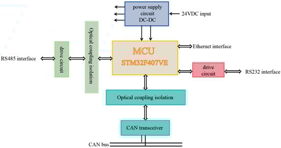
Figure 2.
Main controller node circuit block diagram.
- (3)
- Peripheral Interface Circuit
As a critical component of the embedded simulation controller hardware system, the design rationality of the peripheral interface circuits directly influences the operational efficiency of the entire diesel engine parallel power unit simulation system. In accordance with the functional requirements and application scenarios specific to the embedded simulation controller used in diesel engine parallel power units, this section will provide a systematic exposition of the design methodology for its peripheral interface circuitry.
- (4)
- 4~20 mA Current Input Interface Circuit
The 4~20 mA current input interface circuit constitutes the primary signal acquisition channel for the engine synchronization signal. Its design performance critically influences the accuracy of signal acquisition and the timeliness of system response, thereby directly affecting the speed control precision and operational stability of the diesel engine synchronization system. Due to the essential function of the synchronization signal in the control of parallel diesel power systems, a two-stage signal conditioning architecture is adopted to achieve high-precision and highly reliable current-to-voltage conversion.
The 4~20 mA current signal is first passed through a 200-ohm precision sampling resistor, converting it into a proportional voltage signal ranging from 0.8 V to 4 V. This voltage is then processed by a second-order active low-pass filter, implemented with low-noise operational amplifiers, to suppress noise and enhance signal integrity. The conditioned analog voltage is subsequently digitized by a 12-bit high-resolution analog-to-digital converter (ADC). The schematic of the 4~20 mA current input signal conditioning circuit is presented in Figure 3.
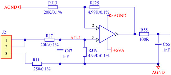
Figure 3.
The 4~20 mA current input circuit schematic diagram.
- (5)
- CAN Interface Circuit.
The main controller node communicates with field I/O nodes through the CAN interface to enable synchronized transmission of control commands and realization of system control functions. Considering the stringent requirements for real-time performance, reliability, and noise immunity in diesel engine parallel operation systems, the CAN interface circuit is designed in compliance with the ISO 11898-2 standard physical layer architecture to facilitate multi-node cooperative control [29].
Since the STM32F407ZE microcontroller incorporates an on-chip CAN controller, only an external CAN transceiver is required. The PCA82C250 CAN bus transceiver from NXP Semiconductors(NXP Semiconductors NV, Eindhoven, The Netherlands) was selected for this purpose. This industrial-grade transceiver supports communication rates of up to 1 Mbps and interfaces directly with the physical bus to transmit and receive differential signals. The PCA82C250 integrates internal current-limiting protection; in the event of a bus short circuit, it restricts the output current to a safe range. It also includes a thermal shutdown feature that disables the output when the junction temperature exceeds 160 °C to prevent damage to the device. Normal operation resumes automatically once the temperature falls below the safety threshold, significantly improving the fault tolerance of the circuit under harsh environmental conditions.
To mitigate electrical interference between the internal system components and the bus, a P121U31 high-speed optocoupler (2Pai Semi, Shanghai, China) is employed between the CAN transceiver and the MCU, providing galvanic isolation for signal transmission. Furthermore, SMBJ6.5CA bidirectional transient voltage suppression (TVS) diodes(STMicroelectronics, Geneva, Switzerland) are connected in parallel between the CAN_H and CAN_L pins of the PCA82C250 and the bus. These diodes offer rapid clamping of transient overvoltages, limiting the voltage to within 6.5 V and thereby protecting the transceiver from potential damage. The circuit schematic of the CAN bus interface for the main controller node is illustrated in Figure 4.
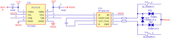
Figure 4.
Main controller CAN bus interface circuit schematic diagram.
- (6)
- Ethernet Interface Circuit
The Ethernet interface circuit functions as the high-speed data channel between the embedded simulation controller of the diesel engine parallel operation power system and the upper-level monitoring system. It undertakes critical tasks, including simulation parameter configuration, real-time data uploading, and reception of remote monitoring commands. Its communication performance directly influences the system’s debugging efficiency and remote controllability.
To fulfill the demands for high-speed and stable data transmission within the diesel engine parallel operation system, this interface employs the HR911103A Ethernet physical layer transceiver (Hanrun Electronics, Shenzhen, China) as its core component. The HR911103A supports 10/100 Mbps auto-negotiation and is compatible with both MII and RMII interface modes. It communicates with the integrated MAC controller in the microcontroller unit (MCU) via the RMII interface. For enhanced signal integrity and protection, an SLVU2.8-4 four-channel low-capacitance TVS diode array is utilized to provide electrostatic discharge (ESD) protection for the Ethernet differential signal lines.
The HR911103A-based Ethernet interface circuit demonstrates stable operation in complex electromagnetic environments, thereby offering reliable hardware support for high-speed data exchange between the main controller and the host computer. This ensures the effective execution of remote monitoring and parameter configuration functions essential to the diesel engine parallel operation system. The corresponding circuit schematic is provided in Figure 5.
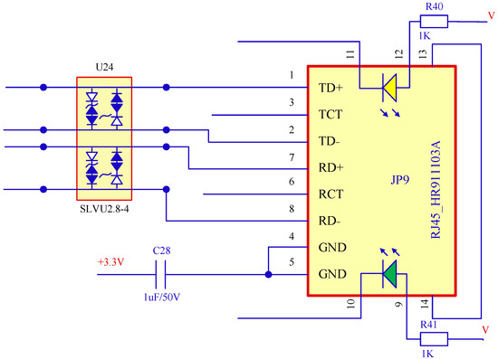
Figure 5.
Ethernet interface circuit schematic diagram.
- (7)
- RS485 Interface Circuit
The main controller node incorporates an RS485 interface to enable interconnection with external RS485-compatible devices while also providing capabilities for data transmission and future system expansion. RS485 communication relies on differential signaling for robust information transfer. This interface must satisfy stringent industrial requirements for communication reliability, noise immunity, and extended transmission distance—particularly in diesel engine environments characterized by strong electromagnetic interference—to ensure stable and error-free data exchange.
The circuit design centers around the TP8485E-SR transceiver, which integrates two independent RS485 transceiver channels and operates in half-duplex mode. Compliant with the IEC 61000-4-2 standard [30], the device is compatible with multiple logic level interfaces and supports a maximum data rate of 20 Mbps, accommodating a wide range of application scenarios.
In the implemented circuit, the RO and DI pins of the TP8485E-SR are connected to the receive and transmit ports of the microcontroller, respectively. The RE and DE control pins are linked through inverters to form transmit/receive control logic that ensures reliable switching between communication states. To enhance signal integrity, 10 Ω pull-up and pull-down resistors are installed on the A and B bus lines to maintain stable logic levels during idle conditions. Additionally, SMBJ6.5CA TVS diodes are placed in parallel between the RS485 interface and the MCU main circuit to provide electrical isolation, suppress noise voltages induced on the bus, and improve the operational stability of the core microcontroller circuitry. The schematic of the RS485 interface circuit is presented in Figure 6.
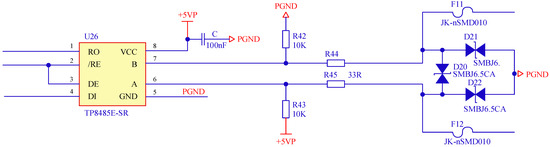
Figure 6.
RS485 interface circuit schematic diagram.
3. Model-Based Embedded Simulation Program Design
- (1)
- Simulation Model
The diesel engine parallel operation model functions as the controlled object for the embedded simulation controller. It is developed using a modular architecture within the MATLAB/Simulink environment. Through the coordinated operation of two independent diesel engine submodels and a dedicated parallel operation controller, the system achieves a high-fidelity dynamic simulation of the diesel engine parallel operation process.
Guided by a modular design philosophy, each individual diesel engine is decomposed into functionally distinct submodules—such as the governor, turbocharger, intercooler, and intake manifold. Mathematical models for these components are derived from thermodynamic and control-theoretic principles, with data exchange facilitated through standardized interfaces.
Furthermore, the parallel operation controller is implemented using Stateflow, enabling advanced logical decision-making capabilities to synchronize and regulate the operational states of the two diesel engines. This integrated design approach yields a comprehensive and functionally complete simulation platform for dual-engine parallel operation.
As the core component responsible for speed regulation, the governor employs a PID control algorithm to dynamically adjust the fuel flow rate. Its input consists of the deviation between the speed command, issued by the parallel operation controller, and the actual rotational speed. The output of the governor corresponds to a fuel flow correction factor. By modulating the effective injection pulse width of the fuel injector, the governor achieves closed-loop speed control. Through theoretical analysis and validation against empirical data acquired from actual marine engines, the mathematical model of the governor is formulated as follows:
where is the proportional coefficient; is the integration constant; and is the speed deviation.
Under steady-state operating conditions (speed range: 250–400 r/min), the fuel flow correction factors generated by the governor model were compared with experimental data obtained from marine diesel engine bench tests. At the core operating speed of 350 r/min, the deviation between the model-predicted correction factor and the measured value was within 1.2%. Across the load range of 25% to 100%, the average deviation between the simulated and measured correction factors remained below 1.3%, confirming the model’s high steady-state accuracy. In transient performance tests involving a 30% step load increase, the deviation in the 90% response time between the simulated fuel flow correction coefficient and the measured data was less than 5%, while the overshoot deviation was controlled within 7%. These results indicate that the model effectively reproduces the actual dynamic response behavior of the governor. The quantitative findings demonstrate that the proposed governor model reliably captures both steady-state regulation characteristics and transient response performance, thereby validating its suitability in parallel vehicle system simulations.
The turbocharger module is developed based on the principles of aerodynamics and thermodynamics. In the compressor stage, the intake boost pressure is determined according to the rotational speed and pressure ratio characteristics. Meanwhile, the turbine stage utilizes exhaust gas energy to drive the rotor assembly. These two stages are mechanically coupled via a rigid shaft, and their dynamic behavior is described by the following equation:
where is the rotational inertia of the rotor; is the speed of the supercharger; is the output torque of the turbine; is the torque consumed by the compressor; and is the torque lost due to friction.
Under steady-state operating conditions (speed range: 250–400 r/min), key parameters from the turbocharger model—including compressor outlet pressure and turbine speed—were compared with experimental data obtained from marine diesel engine bench tests. At the core operating speed of 350 r/min, the deviations between the model predictions and measured values for both parameters were within 2%. Across the 25–100% load range, the average deviation between simulated and measured results remained below 2.5%, confirming the model’s steady-state accuracy. In transient tests involving a 30% step load increase, the model successfully reproduced the turbocharger speed rise process and the dynamic response of compressor pressure, showing strong agreement with experimental measurements. The deviation in regulation time was less than 150 ms, and the overshoot error was within 0.8%, accurately capturing the system’s dynamic behavior. These results demonstrate that the turbocharger model reliably represents both steady-state performance and transient response characteristics, validating its applicability in parallel vehicle system simulations.
The intercooler module is constructed based on heat transfer principles, and the gas temperature at the intercooler outlet is:
The gas pressure at the outlet of the intercooler is:
where is the compressor outlet pressure; is the pressure loss through the intercooler; is the compressor outlet temperature; is the intercooler efficiency; and is the intercooler cooling water outlet temperature.
Under steady-state operating conditions (speed range: 250–450 r/min), key parameters of the intercooler model—including inlet/outlet temperatures and cooling efficiency—were validated against experimental data obtained from marine diesel engine bench tests. At the core speed of 350 r/min, the deviations between the simulated and measured values for all parameters remained below 2%. Across the load range of 25% to 100%, the average deviation did not exceed 2.3%, confirming the model’s accuracy under steady-state conditions. During transient tests involving a 30% step load increase, the model effectively captured the dynamic variation in intercooler outlet temperature, showing close agreement with experimental measurements. The deviation in temperature regulation time was less than 150 ms, and the steady-state temperature error was within 0.6%, demonstrating the model’s capability to reproduce dynamic behavior. These results indicate that the intercooler model accurately represents both steady-state and transient performance, supporting its reliability for integration into parallel operation system simulations.
The intake manifold module is formulated based on the principle of mass conservation. Under transient operating conditions, the rate of change of mass within the intake manifold volume is governed by the difference between the air mass flow rate entering from the compressor and the air mass flow rate exiting into the diesel engine cylinders, as expressed by the following equation:
where is the air mass in the intake manifold container; is the air mass flow rate in the compressor; and is the air flow rate of the diesel engine.
The coordinated control of the parallel operation system is realized via a dedicated parallel operation controller developed in Stateflow. This controller takes as inputs the connection/disconnection status, real-time rotational speed, and load conditions of both diesel engines. Utilizing state-machine logic, it partitions the parallel operation process into distinct phases and triggers transitions between corresponding control strategies. Data exchange between the diesel engine models and the parallel operation controller is facilitated through signal lines. In summary, the overall architecture of the parallel operation system simulation model, implemented in MATLAB/Simulink, is illustrated in Figure 7.
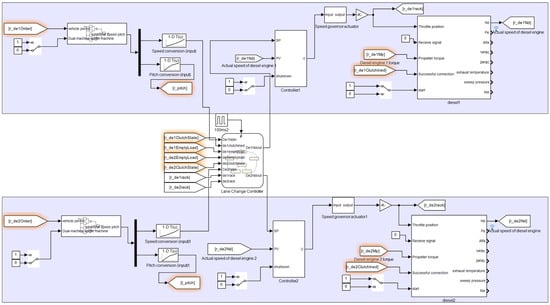
Figure 7.
Lane change system simulation model.
- (2)
- Real-Time Code and Interface Program Design for Models
The conversion of a MATLAB/Simulink-based model of a diesel engine parallel operation system into executable code for the main controller is accomplished using the MATLAB Embedded Coder toolchain, enabling full automation of the translation process from graphical models to embedded code. To generate embedded real-time code tailored to specific hardware, appropriate parameters must first be configured within the MATLAB/Simulink modeling environment. This configuration is performed via the Configuration Parameters window, where critical parameters are defined as follows:
- (a)
- The solver is configured to operate in fixed-step mode, ensuring that the fundamental simulation step size is strictly synchronized with the model execution cycle.
- (b)
- Code generation is configured to use the Embedded Real-Time (ERT) target (ert.tlc), with the target language specified as C, and the toolchain setting defined as “Automatically locate an installed toolchain”.
- (c)
- The hardware implementation interface specifies the parameters of the target processor, with the device vendor designated as ARM Compatible and the device type selected as ARM Cortex-M.
The code generation process primarily consists of the following key steps: The Real-Time Workshop (RTW) engine reads the model.mdl file and performs compilation, producing an intermediate description file (model.rtw) that captures the structure and components of the Simulink model. Subsequently, the Target Language Compiler (TLC) processes the model.rtw file to generate corresponding C source code. Using the specified target compilation tools, each module is compiled and linked. A custom makefile is then created to direct the linker in compiling and linking the generated source code with the main program, library files, and any user-defined modules. Finally, an executable file is produced.
To facilitate the migration of the simulation model to executable code on the main controller, hardware peripheral driver modules must be incorporated into the virtual prototype to construct a hardware abstraction layer. These modules—such as analog output and digital input/output modules—establish a mapping between the model’s signal interfaces and the physical hardware ports. After compilation and downloading of the code, this mapping mechanism associates the virtual ports with the actual physical channels of the target hardware.
To improve system maintainability, the design employs “From” and “Goto” modules from the Simulink library to implement cross-module signal routing and management. The overall process of real-time code generation and deployment to the main controller is depicted in Figure 8.
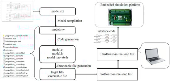
Figure 8.
Real-time code generation and embedding process diagram from model to main controller.
4. Results
Building upon the aforementioned embedded simulation controller, the functional modules of the monitoring program and the human–machine interface (HMI) were developed using the LabVIEW software (LabVIEW 2024 Q1) platform. Real-time data were transmitted to the host computer via the Ethernet communication interface established with the controller.
Initial tests were conducted on the startup and shutdown procedures of the dual-engine system. As illustrated in Figure 9, the changes in engine speed following the initiation and cessation of the main engine under no-load and exhaust-cutoff conditions are presented. The speed range from 0 to 60 rpm corresponds to the high-pressure air-blowing stage, while the range from 60 to 400 rpm represents the ignition stage. The startup process is completed in approximately 20 s, and the shutdown process requires approximately 45 s.
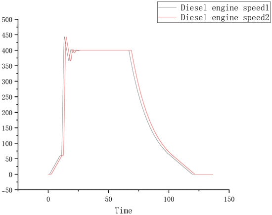
Figure 9.
Host start–stop speed change graph.
Based on this foundation, tests were conducted on the automatic mode connection and disconnection procedures during dual-engine parallel operation, as illustrated in Figure 10. The initial phase spans approximately 0–20 s, during which the system awaits speed stabilization at the target value of 400 rpm. Around the 50-s mark, the first main engine is connected to the exhaust system. Following this connection, the engine speed experiences a transient drop due to the increased load. In response, the governor significantly increases the fuel injection volume to augment the engine’s output torque, prompting a subsequent recovery in speed. By approximately 75 s, the speed of the first engine stabilizes again at 400 rpm.
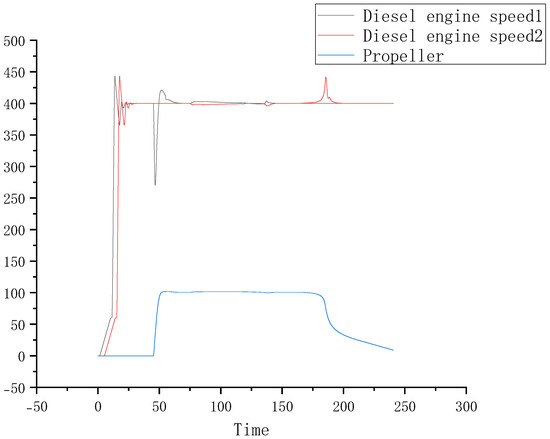
Figure 10.
Automatic mode merging and separation process speed change chart.
At this point, the second main engine is connected, exhibiting speed behavior consistent with that of the first engine. After approximately 125 s, the speed of the second engine also stabilizes at 400 rpm. Once both engines operate in parallel and their speeds are steady, Engine No. 1 begins the decoupling process. The disconnection results in a temporary speed increase due to load removal, after which the governor acts to reduce and stabilize the speed at 400 rpm. Engine No. 1 successfully decouples at around 150 s.
The second engine begins decoupling at approximately 175 s, demonstrating speed dynamics similar to those of the first during disconnection. It successfully decouples at around 200 s, with both engines ultimately stabilizing at the target speed of 400 rpm.
Throughout the automatic connection and disconnection tests, the speeds of both diesel engines remained closely matched with minimal deviation, consistently stabilizing near the set value. These results confirm that the system fully complies with the stringent speed stability requirements essential for actual parallel operation. The findings demonstrate that the controller’s simulation logic for parallel operation is both precise and effective, facilitating smooth transitions during diesel engine synchronization and satisfying all specified simulation control objectives.
Additionally, tests were performed on the manual-mode dual-unit parallel operation and disconnection procedures, as depicted in Figure 11. During manual parallel operation, the variations in rotational speed were consistent with those observed under automatic mode. After successful synchronization of the two units, at approximately 130 s, Unit 1 was unloaded, resulting in a transfer of its load to Unit 2. This load redistribution led to an increase in the rotational speed of Unit 2. The load transfer concluded around 180 s, followed by the disconnection of Unit 1, which subsequently experienced a decrease in speed. By approximately 225 s, the disconnection process was completed, and Unit 1 was shut down. Its speed gradually decreased until it reached 0 rpm at around 275 s, indicating a complete shutdown.
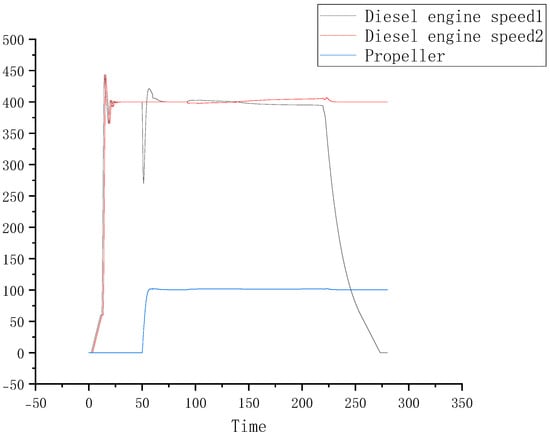
Figure 11.
Manual mode coupling and uncoupling process speed change diagram.
Throughout the manual coupling and decoupling tests, the rotational speed responded as anticipated, with no abnormal fluctuations observed. These results demonstrate that the controller is capable of accurately receiving and executing manual commands and that the simulated speed variations under different instructions are consistent with expected behavior. The system satisfies the stringent speed stability requirements essential for actual operational scenarios, thereby confirming the effective control performance of the controller in manual mode.
5. Conclusions
This paper presents the design and implementation of a model-based embedded simulation controller tailored for diesel engine parallel operation power systems. The proposed controller facilitates model-driven embedded system simulation and demonstrates adaptability to diverse application requirements in parallel power generation unit simulations. A quantitative comparison with existing systems and conventional development approaches confirms its feasibility and effectiveness, particularly in the following two aspects:
- (a)
- Quantitative Improvements in Development Efficiency and Cost. In comparison to traditional manual programming, exemplified by a commercial system requiring ~8000 lines of core C code, the proposed model-driven approach employing Simulink and automatic code generation shortened the core development cycle from 8 weeks to 3 weeks and reduced the average iteration modification time from 48 h to 6 h. Regarding hardware, the STM32F407VE-based controller yields cost reductions of 99.2% and 84% relative to equivalent dSPACE platforms and conventional PLC solutions, respectively.
- (b)
- Quantitative Advantages in Simulation Accuracy and Real-Time Performance. The performance of the proposed system exhibits a marked improvement in the accuracy of parallel dynamic process simulation, significantly reducing errors compared to conventional manually programmed systems.
In conclusion, quantitative comparison results demonstrate that the model-based design method for developing embedded simulation controllers in diesel engine parallel operation power systems can significantly improve development efficiency and reduce costs while ensuring simulation accuracy and real-time performance, with excellent engineering adaptability. Its technical advantages and application value have been clearly verified.
Author Contributions
H.L.’s primary contributions were completing the modeling and drafting the paper. P.S.’s main contributions were the overall scheme design and data analysis. J.W. primarily completed the hardware design. G.C. completed the communication for the embedded development board. All authors have read and agreed to the published version of the manuscript.
Funding
This research received no external funding.
Data Availability Statement
The original contributions presented in this study are included in the article. Further inquiries can be directed to the corresponding author.
Acknowledgments
The authors wish to thank the reviewers for their careful, unbiased, and constructive suggestions, which led to this revised manuscript.
Conflicts of Interest
The authors declare that there are no conflicts of interest.
References
- Zhang, Z.; Lv, J.; Li, W.; Long, J.; Wang, S.; Tan, D.; Yin, Z. Performance and emission evaluation of a marine diesel engine fueled with natural gas ignited by biodiesel-diesel blended fuel. Energy 2022, 256, 124662. [Google Scholar] [CrossRef]
- Savaş, A.; Şener, R.; Uslu, S.; Der, O. Experimental study on performance and emission optimization of MgO nanoparticle-enriched 2nd generation biodiesel: A method for employing nanoparticles to improve cleaner diesel combustion. J. Energy Inst. 2025, 120, 102024. [Google Scholar] [CrossRef]
- Fritzson, P.; Pop, A.; Abdelhak, K.; Ashgar, A.; Bachmann, B.; Braun, W.; Bouskela, D.; Braun, R.; Buffoni, L.; Casella, F. The OpenModelica Integrated Environment for Modeling, Simulation, and Model-Based Development. Model. Identif. Control 2020, 41, 241–295. [Google Scholar] [CrossRef]
- Hueros-Barrios, P.J.; Rodriguez-Sánchez, F.J.; Martín-Sánchez, P.; Tradacete-Ágreda, M.; Santos-Perez, C. Digital Twin Design Framework for Photovoltaic Generation Systems Using FMU and Modelica. In Proceedings of the IEEE 22nd Mediterranean Electrotechnical Conference (MELECON), Porto, Portugal, 25–27 June 2024; pp. 461–466. [Google Scholar] [CrossRef]
- Bassoli, M.; Bianchi, V.; De Munari, I. A Model-Based Design Floating-Point Accumulator. Case of Study: FPGA Implementation of a Support Vector Machine Kernel Function. Sensors 2020, 20, 1362. [Google Scholar] [CrossRef] [PubMed]
- Lee, C.; Koo, Y.; Park, K.; Kim, G. Design of Model-based VCU Software for Driving Performance Optimization of Electric Vehicle. J. Inf. Commun. Converg. Eng. 2023, 21, 351–358. [Google Scholar] [CrossRef]
- Barber, R.; Rosa, D.R.; Flores-Caballero, A.; Garrido, S. Deployment of Model-Based-Design-Adaptive Controllers for Monitoring and Control Mechatronic Devices. Appl. Sci. 2023, 13, 12432. [Google Scholar] [CrossRef]
- Bai, Z.; Zhang, B.; Song, M.; Tian, Z. Rapid Integrated Design Verification of Vertical Take-Off and Landing UAVs Based on Modified Model-Based Systems Engineering. Drones 2024, 8, 755. [Google Scholar] [CrossRef]
- Pathirana, V.; Creasman, S.E.; Chvála, O.; Skutnik, S. Molten salt reactor system dynamics in simulink and modelica, a code to code comparison. Nucl. Eng. Des. 2023, 413, 112484. [Google Scholar] [CrossRef]
- Ebkowski, A.; Koznowski, W. Modeling of an Autonomous Electric Propulsion Barge for Future Inland Waterway Transport. Energies 2023, 16, 8053. [Google Scholar] [CrossRef]
- Park, H.M.; Jung, H.; Oh, T.H.; Oh, S.-K.; Lee, J.M. Stochastic Hybrid Model Predictive Control: Application to Parallel Hybrid Electric Vehicles. IFAC-PapersOnLine 2023, 56, 6672–6677. [Google Scholar] [CrossRef]
- Hao, J.; Ruan, S.; Wang, W. Model Predictive Control Based Energy Management Strategy of Series Hybrid Electric Vehicles Considering Driving Pattern Recognition. Electronics 2023, 12, 1418. [Google Scholar] [CrossRef]
- Lutfi, M.; Valerdi, R. Integration of SysML and Virtual Reality Environment: A Ground Based Telescope System Example. Systems 2023, 11, 189. [Google Scholar] [CrossRef]
- Luccisano, G.; Cordero, S.S.; Gateau, T.; Viola, N. Open-Source Data Formalization through Model-Based Systems Engineering for Concurrent Preliminary Design of CubeSats. Aerospace 2024, 11, 702. [Google Scholar] [CrossRef]
- Ramirez, C.A.; Agrawal, P.; Thompson, A.E. An Approach Integrating Model-Based Systems Engineering, IoT, and Digital Twin for the Design of Electric Unmanned Autonomous Vehicles. Systems 2025, 13, 73. [Google Scholar] [CrossRef]
- Kiran, A.; Zaghari, B.; Kipouros, T.; Dos Reis, R.J.N.D. Application of Model-Based Systems Engineering for the Integration of Electric Engines in Electrified Aircraft. J. Phys. Conf. Ser. 2023, 2526, 012025. [Google Scholar] [CrossRef]
- Chu, C.; Yin, C.; Su, S.; Chen, C. Synchronous Integration Method of System and Simulation Models for Mechatronic Systems Based on SysML. Machines 2022, 10, 864. [Google Scholar] [CrossRef]
- Lyu, W.; Yang, Y.; Miao, J.; Cao, S.; Kong, L. Architecture Preliminary Design and Trade-Off Optimization of Stratospheric Airship Based on MBSE. Aerospace 2024, 11, 582. [Google Scholar] [CrossRef]
- Niu, W.; Jin, C. Model Based Aircraft Thrust Reverse System Design. In Proceedings of the 3rd International Symposium on Aerospace Engineering and Systems (ISAES), Nanjing, China, 22–24 March 2024; pp. 10–13. [Google Scholar] [CrossRef]
- Mudhivarthi, B.R.; Saini, V.; Dodia, A.; Shah, P.; Sekhar, R. Model Based Design in Automotive Open System Architecture. In Proceedings of the 7th International Conference on Intelligent Computing and Control Systems (ICICCS), Madurai, India, 17–19 May 2023; pp. 1211–1216. [Google Scholar] [CrossRef]
- Sun, L.; Gao, F.; L., L.Q.; Lou, B.C. Research on modelling analysis and design method of helicopter operation requirements based on MBSE. J. Phys. Conf. Ser. 2023, 2472, 012042. [Google Scholar] [CrossRef]
- Zhang, J.; Yang, S. Recommendations for the Model-Based Systems Engineering Modeling Process Based on the SysML Model and Domain Knowledge. Appl. Sci. 2024, 14, 4010. [Google Scholar] [CrossRef]
- Huang, Z.; Shang, W.; Wang, Y.; Zhang, A. A Design Method of Civil Aircraft Warning System Based on MBSE. In Proceedings of the International Annual Conference on Complex Systems and Intelligent Science (CSIS-IAC), Guangzhou, China, 20–22 September 2024; pp. 930–935. [Google Scholar] [CrossRef]
- Qin, D.; Dong, H.; Sun, S.; Wen, Z.; Li, J.; Li, T. Model-Driven Cooperative Path Planning for Dynamic Target Searching of Unmanned Unterwater Vehicle Formation. J. Mar. Sci. Eng. 2024, 12, 2094. [Google Scholar] [CrossRef]
- Wang, Q.; Wang, W.; Suzuki, S.; Namiki, A.; Liu, H.; Li, Z. Design and Implementation of UAV Velocity Controller Based on Reference Model Sliding Mode Control. Drones 2023, 7, 130. [Google Scholar] [CrossRef]
- Jian, B.; Wang, H. Hardware-in-the-loop real-time validation of fuel cell electric vehicle power system based on multi-stack fuel cell construction. J. Clean. Prod. 2022, 331, 129807. [Google Scholar] [CrossRef]
- Lei, N.; Zhang, H.; Hu, J.; Hu, Z.; Wang, Z. Sim-to-real design and development of reinforcement learning-based energy management strategies for fuel cell electric vehicles. Appl. Energy 2025, 393, 126030. [Google Scholar] [CrossRef]
- Sellali, M.; Ravey, A.; Betka, A.; Kouzou, A.; Benbouzid, M.; Djerdir, A.; Kennel, R.; Abdelrahem, M. Multi-Objective Optimization-Based Health-Conscious Predictive Energy Management Strategy for Fuel Cell Hybrid Electric Vehicles. Energies 2022, 15, 1318. [Google Scholar] [CrossRef]
- ISO 11898-2:2024; Road Vehicles—Controller Area Network (CAN)—Part 2: High-Speed Physical Medium Attachment (PMA) Sublayer. International Organization for Standardization: Geneva, Switzerland, 2024.
- IEC 61000-4-2:2025; Electromagnetic Compatibility (EMC)—Part 4-2: Testing and Measurement Techniques—Electrostatic Discharge Immunity Test. International Electrotechnical Commission: Geneva, Switzerland, 2025.
Disclaimer/Publisher’s Note: The statements, opinions and data contained in all publications are solely those of the individual author(s) and contributor(s) and not of MDPI and/or the editor(s). MDPI and/or the editor(s) disclaim responsibility for any injury to people or property resulting from any ideas, methods, instructions or products referred to in the content. |
© 2025 by the authors. Licensee MDPI, Basel, Switzerland. This article is an open access article distributed under the terms and conditions of the Creative Commons Attribution (CC BY) license (https://creativecommons.org/licenses/by/4.0/).