Abstract
To address the stability control challenges of narrow coal pillar roadways along goaf-sides affected by thick coal seam secondary mining, this study investigates the 51507 track gateway in Liuyuanzi Coal Mine through theoretical analysis, numerical simulation, and field testing. The research focuses on stress evolution and energy distribution characteristics during secondary mining extraction. Key findings include the following: (1) Under the superimposed influence of goaf-side abutment pressure and secondary mining front abutment pressure, roadway surrounding rock exhibits regional asymmetric characteristics in energy dissipation. (2) Within 10 m ahead of the secondary mining face, the coal pillar experiences intense energy dissipation and plastic zone penetration, leading to bearing structure failure. (3) The energy mechanism reveals that asymmetric dissipative energy distribution drives plastic zone expansion. Accordingly, an integrated control strategy combining differentiated support (bolts/cables + tension-type opposite anchor cables + hydraulic props) with coal pillar grouting modification was developed. Field implementation demonstrated effective control of surrounding rock deformation within 200 mm. This study provides theoretical foundations and technical references for roadway stability control under similar mining conditions.
1. Introduction
According to statistics, thick coal seams with a deposit thickness greater than 3.5 m account for approximately 45% of China’s total recoverable reserves. As coal mining gradually shifts to deeper regions, the use of wide coal pillars for roadway protection in thick coal seams results in significant coal resource loss [1,2]. To improve resource recovery rates, meet auxiliary transportation needs, and address tight production schedules, the double-roadway layout with narrow coal pillar protection technology in thick coal seams has been increasingly adopted. However, this approach leads to retained roadways being affected by secondary mining, making surrounding rock control and goaf isolation under narrow coal pillar conditions more challenging. These issues severely impact mine production safety and hinder safe and efficient coal mining.
To address the stability control challenges of narrow coal pillar roadways, numerous scholars have conducted extensive research and discussions on strata behavior patterns and control technologies [3,4,5,6,7,8]. Zhang Baisheng et al. [9] investigated the stability control of narrow coal pillar roadways in thick coal seams using the roof-cutting pressure relief method, analyzing the selection of technical parameters and summarizing the process. Gu Changwan et al. [10] proposed a bidirectional reinforcement technology using a tension-type opposite anchor cable (swell-lock penetrating cables) for narrow coal pillar roadways, addressing the difficulty of effective reinforcement, and conducted industrial trials. Zhao Hongbao et al. [11] studied the asymmetric failure characteristics of narrow coal pillar roadways under dynamic loading disturbances, obtaining insights into stress, energy, and excavation unloading features of the roadway floor. Chen Zhengzheng et al. [12] analyzed the overlying strata movement and deformation failure patterns of narrow coal pillar roadways, revealing the mechanical mechanism of non-uniform failure, and proposed a differentiated control scheme involving targeted grouting and increased support density in critical areas.
Domestic and international scholars have conducted thorough research on the failure mechanisms and support technologies of retained roadways in double-roadway layouts [13,14,15]. Huang Wanpeng et al. [16] conducted in-depth research on the principles of double-roadway layout with narrow coal pillars and coal pillar reinforcement technology, proposing a high-strength composite support technology combining penetrating cables and concrete-filled steel tube piers. Wu Xiangye et al. [17] explored the spatiotemporal evolution of plastic zones in retained roadways under double-roadway layouts and investigated their spatial failure patterns and control methods. Liu Hongtao et al. [18] analyzed the stress distribution and plastic zone morphology of retained roadways under superimposed mining-induced stress fields, revealing the asymmetric expansion mechanism of surrounding rock under superimposed mining influences. However, systematic research on the evolution mechanism and control of plastic zones in narrow coal pillar roadways under superimposed stress–energy fields during secondary mining remains lacking.
Therefore, based on the engineering background of narrow coal pillar retained roadways adjacent to the goaf in Liuyuanzi Coal Mine, this study analyzes the stress and energy evolution patterns of retained roadways during secondary mining. Combined with the distribution characteristics of plastic zones in the surrounding rock, the formation mechanism of plastic zones is revealed from an energy perspective. A coordinated control scheme and parameters are proposed, and industrial trials are conducted. The aim is to provide valuable research foundations and references for addressing surrounding rock control challenges under such conditions.
2. Engineering Overview and Failure Characteristics of Roadway Surrounding Rock
2.1. Engineering Overview
The No. 5 coal seam in Liuyuanzi Coal Mine is the primary mineable seam, with an average thickness of 6.26 m, a simple structure, and a dip angle of 3–7°, making it a stable near-horizontal thick coal seam. The strike length of the 51507 working face is 935 m, and the inclined length is 170.5 m. The eastern side of the working face borders the fully mechanized top-coal caving goaf of the 51509 working face, which has already been mined out. Both working faces are arranged along the strike direction, employing the long wall retreating mining method with full-seam caving for roof management. The width of the inter-roadway coal pillar is 8 m. The 51507 track gateway has an average burial depth of 455 m, with 0.5 m of bottom coal left during excavation. The designed cross-section is rectangular, with dimensions of width × height = 4600 × 3300 mm. Based on geological data, the mine’s geographical location, the comprehensive coal seam columnar diagram, the comprehensive coal seam histogram, and the layout plan of the working face and roadways are shown in Figure 1.
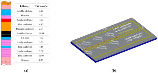
Figure 1.
Mine regional location and working face overview: (a) geographical location; (b) comprehensive columnar section of coal seam.
The coal wall refers to the solid coal mass boundary on the side of the roadway opposite the goaf, serving as the extraction boundary for the 51507 working face during mining. It directly bears the advanced abutment pressure from secondary extraction, with its stability critically influencing roadway convergence deformation. As a key component of lateral load-bearing capacity, it plays a pivotal role in roadway stability.
The coal pillar denotes the reserved coal isolation body between the 51507 track roadway and the 51509 goaf, fulfilling dual functions of roadway protection and goaf isolation. Acting as the core bearing zone during secondary extraction, it simultaneously accommodates both lateral abutment pressure from the goaf and advanced abutment pressure from secondary mining. Its stability fundamentally determines overall roadway safety, constituting the primary focus of surrounding rock control in this study.
The roof comprises a composite system of coal strata and rock layers above the roadway, directly supporting the overlying 420 m loose strata load and pressures induced by overlying rock movements. As the critical zone for preventing roof collapse, its mechanical behavior significantly influences roadway integrity.
The floor refers to the composite structure of coal seams and rock strata at the roadway bottom, subjected to lateral stresses induced by coal wall and pillar abutment pressures. The hydro-mechanical weakening effect (water-induced strength degradation of rock strata) renders the floor prone to heave deformation, constituting a typical zone of experimentally observed asymmetric failure.
Additionally, a three-dimensional geometric schematic of the roadway is presented in Figure 2.
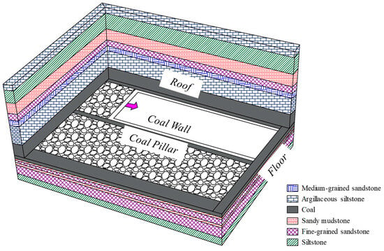
Figure 2.
Three-dimensional geometric schematic of roadway.
2.2. Failure Characteristics of Surrounding Rock in Retained Roadway During Secondary Mining
After the mining of the upper section (51509 working face), the redistribution of surrounding rock stress caused the overlying strata’s gravitational load to transfer toward the periphery of the goaf. During the mining of the 51507 working face, the retained roadway was subjected to superimposed effects from the advanced abutment pressure of the working face and the lateral stress concentration of the goaf, leading to intensified deformation and failure of the surrounding rock. Local roof collapses and rib spalling were observed, as shown in Figure 3.
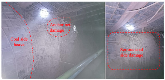
Figure 3.
Photographs of deformation and failure at the gob-side entry retaining (GER) site.
To determine the deformation and failure characteristics of the retained roadway during secondary mining, the cross-point method was employed to monitor the surface displacement of the 51507 track gateway. Monitoring points were arranged every 100 m within the 0–500 m range along the excavation direction of the track gateway, as shown in Figure 1.
Measurement point arrangement method: Four boreholes (designated as a, b, c, d in Figure 4) are installed along the vertical line of the roof–floor and the horizontal line of both sidewalls in the roadway. The boreholes should meet the following specifications: diameter ≥ 28 mm, depth ≥ 400 mm. After wooden stakes matching the borehole dimensions are inserted, curved measurement nails are installed at the ends of the roof and left sidewall wooden stakes, while flat-headed nails are fixed at the ends of the floor and right sidewall wooden stakes. The surface displacement of the surrounding rock is monitored using the relative change observation method, where the initial measurement data serves as the reference baseline. The displacement value is calculated by subtracting each subsequent observation from the first measurement, with an accuracy requirement of ±1 mm.
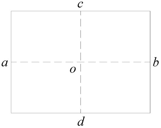
Figure 4.
Example diagram of cross-sectional monitoring point arrangement.
The measurement methods for different points are as follows: The measurement of roof–floor convergence, roof subsidence, and floor heave is conducted by stretching a measuring tape between points a and b, followed by recording the values of c-d and c-o using a steel ruler. The value of c-d represents the distance between the roof and floor, while c-o denotes the vertical distance from the roof to the central point o, and d-o indicates the distance from the floor to the same central point o. The roof–floor convergence, roof subsidence, and floor heave values are calculated for each observation cycle. The measurement of both-sidewall convergence, left-sidewall convergence, and right-sidewall convergence is conducted by stretching a measuring tape between points c and d, followed by recording the values of a-o and a-b using a steel ruler. a-b represents the horizontal distance between both sidewalls, a-o denotes the distance from the left sidewall to the roadway centerline, and o-b is the distance from the right sidewall to the roadway centerline. Both-sidewall convergence, left-sidewall convergence, and right-sidewall convergence are calculated for each observation cycle.
The convergence deformation of the roof, floor, and ribs was recorded every 15 days, with the monitoring results presented in Figure 5.
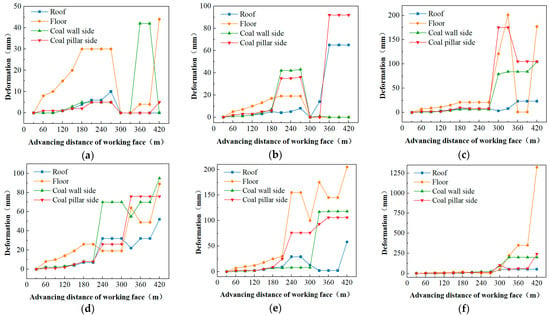
Figure 5.
Surrounding rock deformation amounts at different monitoring positions along the GER: (a) Surrounding rock deformation at 0 m. (b) Surrounding rock deformation at 100 m. (c) Surrounding rock deformation at 200 m. (d) Surrounding rock deformation at 300 m. (e) Surrounding rock deformation at 400 m. (f) Surrounding rock deformation at 500 m.
During the advance of the 51507 working face by 420 m, the monitoring points at 0 m, 100 m, 200 m, and 300 m were located outside the influence range of the secondary-mining-induced stress, being affected only by the lateral stress concentration from the 51509 goaf. As shown in Figure 5a–d, under the influence of lateral stress concentration from the goaf, the convergence deformation of the roof, floor, and ribs in the retained roadway was less than 200 mm, indicating stable and controllable surrounding rock conditions with negligible deformation. However, as shown in Figure 5e, when the working face advanced to 390 m (135 m ahead of the 400 m monitoring point), the influence of secondary mining began to manifest at this location, with a significant increase in surface deformation of the roof and floor. By the time the face advanced to 420 m, the deformation of the roof and floor at this location reached 44 mm and 205 mm, respectively.
As shown in Figure 5f, when the working face advanced to 420 m (15 m ahead of the 500 m monitoring point), the surface displacement of the floor and coal pillar rib at this location increased significantly. The convergence deformation of the roof, floor, coal pillar rib, and coal wall rib reached 51 mm, 324 mm, 200 mm, and 242 mm, respectively. This demonstrated an asymmetric failure pattern characterized by severe floor heave, greater deformation in the coal pillar rib compared to the coal wall rib, and relatively stable roof conditions. The significant contraction of the roadway cross-section severely impacted the safe and efficient production of the working face.
3. Stress–Energy Evolution Laws of Surrounding Rock in Narrow Coal Pillar Roadways During Secondary Mining in Thick Coal Seams
According to the fundamental laws of thermodynamics, energy dissipation leads to the continuous increase in plastic strain in rock until failure, which is the intrinsic attribute of roadway surrounding rock deformation and failure. This process reflects the gradual weakening and eventual loss of internal strength in the surrounding rock. The energy dissipation behavior of rock is closely related to its stress state and lithological properties [19,20]. Therefore, an energy calculation numerical model is established to study the stress–energy evolution laws of surrounding rock during secondary mining in narrow coal pillar roadways within thick coal seams.
3.1. Numerical Model Establishment
To investigate the stress–energy evolution laws of surrounding rock during secondary mining in narrow coal pillar roadways within thick coal seams, a FLAC3D three-dimensional numerical model was developed based on the engineering geological conditions of Liuyuanzi Coal Mine [21,22]. The Mohr–Coulomb constitutive model was adopted, with model dimensions of 530 m × 1000 m × 76 m (x × y × z), as shown in Figure 6. The mesh size of the surrounding rock cells in the 51507 track gateway was refined to 0.5 m. The overlying strata thickness was 420 m, so a vertical load of 10.5 MPa was applied to the top surface to simulate the self-weight of the loose overburden. The sides and bottom of the model were fixed constraints. The lateral pressure coefficient was set to 1.5, and the initial stress gradient was 0.025 MPa. The physical and mechanical parameters of the rock are listed in Table 1.
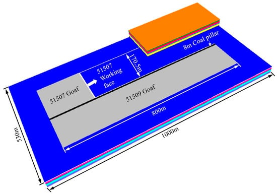
Figure 6.
Three-dimensional numerical model.

Table 1.
Rock mechanics parameters.
Based on the actual mining conditions and advance rate of the 51507 working face, an internal excavation method was employed in the model. A 10 m coal pillar was left along the strike direction of the coal seam, and each mining advance was simulated as 5 m. The double-yield constitutive model was used to simulate the caved zone filling in the fully mechanized top-coal caving face. Specifically, for every 5 m of face advance, 5 m of goaf was backfilled, and the model was solved to equilibrium. This “excavate-fill” simulation approach aimed to achieve realistic simulation results.
Following the excavation of the working face, the overlying roof strata above the goaf collapse and fill the goaf. The collapsed rock mass zone is termed the caving zone.
The height of the caving zone is influenced by factors such as roof rock properties and mining height and can be calculated using the following formula:
where hc is the caving zone height (m); hm is the mining height of coal seam (m); c1 and c2 are correction coefficients, with their parameter values provided in Table 2.

Table 2.
Calculation coefficient of average height of caving zone.
The No. 5 coal seam in this mine has an average mining height of 6.26 m, with the immediate roof composed of silty mudstone exhibiting an average uniaxial compressive strength ranging from 20 to 40 MPa. By selecting appropriate parameters from Table 1 for calculation, the caving zone height is determined to be 12.93 m.
After the excavation of the working face, the overlying strata progressively collapse, and the goaf rock mass is gradually compacted, during which the mechanical properties of the rock mass exhibit a dynamic evolution process. The Salamon constitutive model is employed to characterize the stress–strain relationship of the goaf rock mass and has been widely applied in engineering practice [23].
where σ is the vertical stress acting on the goaf rock mass (MPa); εg is the strain induced by vertical stress in the goaf rock mass; E0 is the initial modulus of the goaf rock mass (GPa).
The maximum strain of the goaf rock mass under vertical stress can be calculated by Equation (3).
where bg is the bulking factor of the goaf rock mass; εgmax is the maximum strain of the goaf rock mass.
where σc is the uniaxial compressive strength of the caved rock mass (MPa).
The average uniaxial compressive strength of roof argillaceous siltstone, determined through laboratory testing, is 36.8 MPa. Substituting this value into the aforementioned equation yields a bulking factor (bg) of 1.484, a maximum strain (εgmax) of 0.326, and an initial modulus (E0) of 21.29 GPa for the goaf rock mass.
The parameters of the double-yield model for the caving zone are obtained by comparing the theoretical stress–strain relationship of a representative unit within the goaf with numerical simulation results from uniaxial compression tests, as presented in Table 3.

Table 3.
Parameters of the double-yield model.
For energy analysis of secondary mining in thick coal seam roadways with narrow coal pillars, it is necessary to establish a numerical energy model for calculation [24,25]. Assuming no heat exchange occurs during the deformation process of rock mass units under external forces, the calculation of dissipated energy satisfies the following relationship based on the first law of thermodynamics:
where Ud is the dissipated energy of the rock mass unit, U is the total energy generated by external work, and Ue is the releasable elastic strain energy of the rock mass unit. U can be expressed as
where σ1, σ2, and σ3 are the maximum, intermediate, and minimum principal stresses of the rock mass unit, respectively, and ε1, ε2, and ε3 are the total strains in the three principal stress directions of the rock mass unit.
Ue can be expressed as
where E is the elastic modulus of the rock mass and µ is Poisson’s ratio.
The above calculation method for rock mass energy dissipation was implemented in the FLAC3D model using FISH language to perform energy computations.
*Pb—in situ rock breakdown pressure; Pr—rupture surface reopening pressure; Ss—rupture surface closing pressure; Sh—horizontal minimum principal stress; SH—horizontal maximum principal stress; Sv—vertical principal stress. The vertical stress Sv is calculated by taking the bulk weight of the overlying rock as 2.5 g/cm3
3.2. Evolution Laws of Abutment Pressure in Surrounding Rock During Secondary Mining
During secondary mining, the stress environment of the retained roadway surrounding rock changes under the combined influence of the lateral abutment pressure from the goaf and the advance abutment pressure from secondary mining. The evolution of vertical stress distribution in the coal seam during the mining of the 51507 working face was simulated, with the 3D view shown in Figure 7.
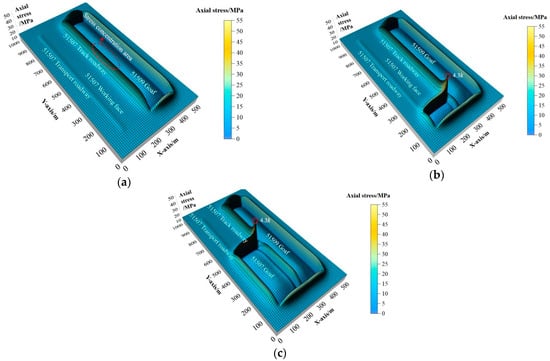
Figure 7.
Three-dimensional distribution maps of vertical stress in the surrounding rock under different advancing distances during secondary mining: (a) secondary mining at 0 m; (b) secondary mining at 100 m; (c) secondary mining at 400 m.
As shown in Figure 7a, after the completion of mining in the 51509 working face, the central part of the goaf was compacted, and the stress recovered to approximately 12.2 MPa, close to the in situ stress. A stress concentration zone formed around the goaf, with the peak vertical stress reaching 30.2 MPa (stress concentration factor of 2.48). The vertical stress environment of the surrounding rock in the retained roadway was about 24.5 MPa (stress concentration factor of 2.01). Figure 7b,c show that as the secondary mining advance distance increased, the peak vertical stress on the coal pillar side reached 43 MPa under the superimposed effects of lateral stress concentration from the goaf and advance stress concentration from the working face. The peak stress location remained approximately 10 m ahead of the working face, with a stress concentration factor of 3.52. The stress environment of the retained roadway surrounding rock deteriorated, and the affected range of mining-induced disturbances extended about 70 m.
3.3. Evolution Characteristics of Dissipated Energy Distribution in Retained Roadway Surrounding Rock During Secondary Mining
3.3.1. Evolution Laws of Dissipated Energy Distribution in Roof, Floor, and Ribs of Retained Roadway
To clarify the range and degree of superimposed stress disturbances on the retained roadway during secondary mining, a monitoring section was arranged along the axial center of the roadway (400 m from the stopping line), as shown in Figure 8. The dissipated energy changes in the roof, floor, and ribs of the retained roadway were extracted when the secondary mining face was 100 m, 70 m, 50 m, 30 m, 20 m, 10 m, and 5 m away from the monitoring section. The resulting curves are presented in Figure 9.
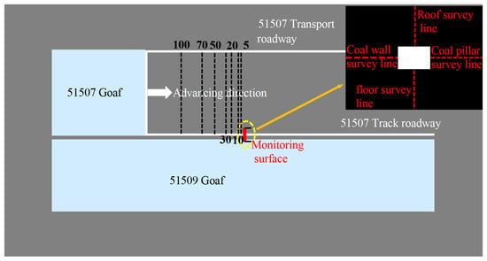
Figure 8.
Schematic diagrams of monitoring surfaces and monitoring line layouts for the GER surrounding rock under different advancing distances during secondary mining.
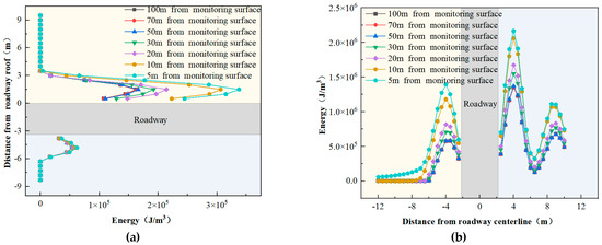
Figure 9.
Distribution curves of dissipated energy in the roof and floor of the GER: (a) distribution curves of dissipated energy in the roof and floor of the GER; (b) distribution curves of dissipated energy in the two sides of the GER.
Overall, the dissipated energy distribution in the retained roadway surrounding rock gradually increased as the secondary mining face advanced. Figure 9a shows that the dissipated energy in the roof and floor exhibited a single-peak distribution, with peak positions located 1.5 m from the roof and floor surfaces. The dissipated energy in the roof increased significantly, with a sharp rise observed when the face was 20 m from the monitoring section. At 5 m from the monitoring section, the peak dissipated energy in the roof reached 3.4 × 10⁵ J/m3. Beyond 3.5 m above the roof surface, almost no energy dissipation occurred. For the floor, the energy dissipation was stable and relatively small, with a peak value of 6.2 × 10⁴ J/m3, when the face was 5 m from the monitoring section. Below 3 m from the floor surface, negligible energy dissipation was observed.
Figure 9b indicates that the dissipated energy in the coal pillar rib was significantly higher than that in the solid coal rib. The coal pillar rib exhibited a double-peak distribution, with peaks located 2 m and 6.5 m from the rib surface. When the face was 5 m from the monitoring section, the peak values reached 2.2 × 10⁶ J/m3 and 1.1 × 10⁶ J/m3, respectively. A trough was observed 4.5 m from the rib surface, with a dissipated energy value of 3.2 × 10⁵ J/m3. This phenomenon occurred because the coal pillar’s internal strength was significantly reduced under the superimposed effects of lateral abutment pressure from the goaf and advance abutment pressure from the working face, leading to greater energy dissipation on both sides of the pillar (adjacent to the goaf) than in the middle. The solid coal rib exhibited a single-peak distribution, with the peak located 2 m from the rib surface. The dissipated energy increased sharply when the face was 20 m from the monitoring section, reaching 1.4 × 10⁶ J/m3 at 5 m from the monitoring section. Beyond 5.5 m from the solid coal rib, the energy dissipation remained stable and relatively low.
3.3.2. Dissipated Energy Distribution in Retained Roadway Surrounding Rock When the Working Face Is 10 m from the Monitoring Section
To investigate the dissipated energy distribution characteristics in different regions of the retained roadway surrounding rock under secondary mining disturbances, monitoring lines were arranged at 1 m intervals from the roof and floor surfaces and at 1 m, 2 m, 4 m, and 6 m from the rib surfaces on the monitoring section (Figure 10). The dissipated energy distribution curves when the working face was 10 m from the monitoring section are shown in Figure 11.
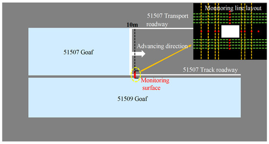
Figure 10.
Schematic diagram of monitoring line layouts for the GER surrounding rock when secondary mining reaches 10 m from the monitoring surface.
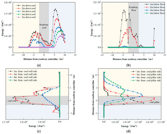
Figure 11.
Evolution curves of dissipated energy distribution at different depths in the GER surrounding rock when secondary mining reaches 10 m from the monitoring surface. (a) Distribution curves of dissipated energy at different depths above the roof; (b) distribution curves of dissipated energy at different depths below the floor; (c) distribution curves of dissipated energy at different depths from the surface of the coal wall side; (d) distribution curves of dissipated energy at different depths from the surface of the coal pillar side.
Figure 11 reveals that when the secondary mining face was 10 m from the monitoring section, the dissipated energy in the retained roadway surrounding rock generally increased with proximity to the roadway surface. Figure 11a shows that the dissipated energy above the roof exhibited a double-peak distribution, with higher values on the coal pillar rib side than on the solid coal rib side. The dissipated energy directly above the roof was stable and relatively low, with a trough near the roof corner of the coal pillar rib. The highest energy dissipation occurred 1 m from the roof surface, with peaks of 7.1 × 10⁵ J/m3 at 2 m on the solid coal rib side and 1.7 × 10⁶ J/m3 at 3.5 m on the coal pillar rib side. Figure 11b indicates that the dissipated energy below the floor followed a single-peak distribution, with the peak located on the solid coal rib side. The energy dissipation decreased from the solid coal rib corner toward the coal pillar rib corner, with minimal mining-induced effects on the coal pillar side. The peak dissipated energy 1 m below the floor was 7.1 × 10⁵ J/m3 at 2.5 m on the solid coal rib side, while negligible dissipation occurred beyond 3 m below the floor. Figure 11c,d show that the dissipated energy in both ribs exhibited single-peak distributions, with higher values in the coal pillar rib than in the solid coal rib. The peaks were generally located near the roof–floor centerline of the ribs. The peak dissipated energy was 1.3 × 10⁶ J/m3 at 1 m from the solid coal rib and 2.2 × 10⁶ J/m3 at 2 m from the coal pillar rib. The energy dissipation was greater near the roof sides than near the floor sides.
In summary, under the superimposed effects of lateral abutment pressure from the goaf and advance abutment pressure from secondary mining, the intense energy dissipation range in the retained roadway surrounding rock extended approximately 10 m ahead of the working face. The closer to the roadway surface, the more severe the energy dissipation. The dissipated energy distribution varied across different spatial regions of the retained roadway, exhibiting an asymmetric pattern: coal pillar rib > roof (coal pillar rib side) > solid coal rib > roof (solid coal rib side) > roof > floor > floor (solid coal rib side) > floor (coal pillar rib side).
4. Energy–Plastic Zone Evolution Laws of Surrounding Rock in Narrow Coal Pillar Roadways During Secondary Mining of Thick Coal Seams
4.1. Distribution Characteristics of Plastic Zones in Retained Roadway Surrounding Rock During Secondary Mining
Under external loading, rocks undergo deformation accompanied by energy dissipation and partial release of stored elastic deformation energy [26]. To investigate the failure process of surrounding rock in narrow coal pillar roadways during secondary mining, the distribution characteristics of elastic deformation energy and plastic zones in the monitoring section were analyzed when the working face advanced to 70 m, 50 m, 30 m, 20 m, 10 m, and 5 m from the monitoring section, as shown in Figure 12.
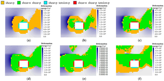
Figure 12.
Distributions of elastic deformation energy and plastic zones in the GER surrounding rock under different advancing distances during secondary mining: (a) 70 m; (b) 50 m; (c) 30 m; (d) 20 m; (e) 10 m; (f) 5 m.
As illustrated in Figure 12, during the secondary mining process toward the monitoring section, elastic deformation energy accumulated at the boundary and deeper regions of the plastic zone in the solid coal rib, with its peak value gradually increasing. When the working face approached 10 m from the monitoring section, the peak elastic deformation energy increased to 5.9 × 10⁵ J/m3. The surrounding rock at the roadway head ahead of the working face completely yielded plastically, resulting in a significant reduction in elastic deformation energy distribution. During the advance from 70 m to 50 m from the monitoring section, the distribution of plastic zones in the roadway surrounding rock remained nearly unchanged. The plastic zone depths were 3.5 m in the roof, 4 m in the solid coal rib, and 2.5 m in the floor. The coal pillar exhibited complete plastic yielding, with notable expansion of the plastic zone at the roof corner of the solid coal rib, showing an overall asymmetric distribution pattern. As mining progressed to 30–20 m from the monitoring section, the plastic zone depth in the solid coal rib expanded to 4.5 m, while the roof and floor plastic zones remained unchanged in depth but significantly increased in range. The plastic zone at the roof corner of the coal pillar rib expanded markedly. By 20 m from the monitoring section, the plastic zones in the roof and ribs of the roadway became interconnected. During the final stage (10–5 m from the monitoring section), the load-bearing structure of the roadway surrounding rock failed. A 3.5 m thick coal mass above the roof yielded plastically, losing its load-bearing capacity.
4.2. Correlation Between Energy and Plastic Zones in Retained Roadway Surrounding Rock During Secondary Mining
To elucidate the formation mechanism of plastic zones in surrounding rock from an energy perspective, the dissipated energy distribution contours and plastic zone boundaries at different distances from the monitoring section were extracted, as shown in Figure 13.
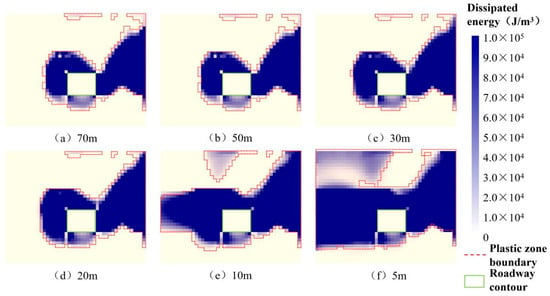
Figure 13.
Nephograms of dissipated energy distribution and outlines of plastic zones in the GER surrounding rock under different advancing distances during secondary mining.
Figure 13 demonstrates that the distribution of plastic zones closely corresponds to the dissipated energy distribution. As secondary mining progressed, the dissipated energy in the monitoring section expanded gradually, with higher energy dissipation observed in the roof and ribs compared to the floor.
During the 70–50 m advance stage, the dissipated energy distribution in the retained roadway surrounding rock remained largely unchanged, while severe energy dissipation occurred inside the coal pillar.
From 30 m to 20 m, the dissipated energy expanded at the roof corner of the coal pillar rib and the floor corner of the solid coal rib, with minimal changes elsewhere.
In the 10–5 m stage, the dissipated energy distribution expanded drastically, with significantly increased energy dissipation in the deeper coal mass of the solid coal rib and its immediate roof strata.
The intense increase in energy dissipation and plastic zone expansion during secondary mining of thick coal seam narrow coal pillar roadways primarily occurred within approximately 10 m ahead of the working face. Severe energy dissipation in the narrow coal pillar led to the breakdown of its internal load-bearing structure, led to the interconnection of plastic zones in the roof, floor, and ribs, and ultimately threatened the stability of the roadway surrounding rock. The dissipated energy distribution suggests that stability control should focus on ensuring the stability of the narrow coal pillar while implementing targeted support for the ribs and their roof corners.
Based on the above analysis, under the superimposed influence of advance abutment pressure and goaf-side abutment pressure during secondary mining, elastic deformation energy accumulates in the deeper stable rock mass of the retained roadway surrounding rock. The asymmetric distribution of dissipated energy in magnitude and orientation induces asymmetric expansion of plastic zones, leading to asymmetric deformation. This reveals the energy-based mechanism behind the asymmetric failure and deformation of surrounding rock in narrow coal pillar roadways during secondary mining.
5. Stability Control of Surrounding Rock in Narrow Coal Pillar Roadway Under Secondary Mining
5.1. Control Concept for Surrounding Rock Stability During Secondary Mining
During the development of the 51507 track haulage roadway, the stability of the roadway was significantly affected by both the primary mining of panel 51509 and subsequent secondary mining of panel 51507 due to the narrow 8 m protective coal pillar. The surrounding rock exists in an asymmetric stress environment. Based on the asymmetric deformation and failure characteristics observed in the 51507 track haulage roadway, targeted reinforcement measures were implemented in energy concentration zones to enhance the support system’s adaptability to asymmetric deformation, requiring differentiated support technology for roadway stability control. The technical approach is manifested in the following aspects:
- (1)
- After roadway excavation, unloading-induced tensile stresses initiate, propagate, and interconnect fractures within the surrounding rock. The asymmetric stress environment formed by mining activities further activates fracture networks in weak zones of the surrounding rock, ultimately triggering asymmetric deformation and failure [27]. Highly prestressed bolts and cables were arranged asymmetrically in different areas to form a differentiated support system through active reinforcement. Strengthened support in energy concentration zones enhances the load-bearing capacity of surrounding rock while effectively reducing mining impacts on the floor.
- (2)
- The numerical simulation results show that the coal pillar in the secondary mining face exhibits fully plastic yield ahead of 70 m. Based on this, the scheme adopts an 8000 mm tension-type opposite anchor cable to strengthen the coal pillar. The field measurement found that support alone could not restore the bearing capacity, so the coal pillar grouting method was used to fill the cracks to improve the strength of the coal pillar, and the “grouting + support” integrated system was constructed in cooperation with the support [28].
- (3)
- The energy dissipation and plastic zone increase sharply when the second mining face is 10 m ahead, and the depth of plastic zone of the roof and coal wall is 3.5 m and 4.5 m, respectively; according to this, hydraulic props are set 20 m ahead to control roof instability of roadway, and lengths of bolts/cables match the depth of plastic zone to ensure that they are anchored to a stable rock layer. Dissipative energy has asymmetric distribution characteristics; according to the asymmetric distribution of dissipated energy, the two sides of the roof are designed to be inclined by 20°, and the upper two sides are designed to be inclined by 15°; plastic zones at the top corner where penetration is easy are reinforced, and floor hardening measures are designed to isolate water damage, suppress floor heave, and balance asymmetric deformation.
- (4)
- The performance of support components and system hierarchy were upgraded to improve the overall strength of the surrounding rock bearing system. Steel straps and bar ladders connect bolts and cables, while tightly meshed metal netting integrates individual support elements into a coordinated bearing system through point–line–surface connection.
In summary, a coordinated control scheme combining differentiated support (bolts/cables + tension-type opposite anchor cable + hydraulic props) with material modification (pillar grouting + floor hardening) was proposed for narrow pillar roadways under secondary mining. This establishes an integrated roof–pillar–floor bearing system that enhances rock mass strength within the structural range and fully utilizes the load-bearing advantages of the combined surrounding rock–support structure, ensuring successful operation of the 51507 track haulage roadway.
5.2. Stability Control Parameters for Surrounding Rock of Retained Roadway During Secondary Mining
This study employs the suspension theory to design bolt parameters.
- (1)
- Bolt length:where L is the total length of the bolt (m); L1 is the exposed length of the bolt (typically 0.15 m); L2 is the effective length of the bolt (m), determined by the Prandtl natural equilibrium arch theory, where the Prandtl pressure arch height equals L2; L3 is the anchored segment length of the bolt (typically 0.3–0.4 m).
When f > 3,
When f ≤ 3,
Here,
where B is the span of the roadway (m); f is the Prandtl rock strength coefficient; H is the excavation height of the roadway (m); φ is the internal friction angle of the rock (°); R is the ultimate uniaxial compressive strength of the rock (MPa).
The average thickness of the No. 5 coal seam in Liuyuanzi Coal Mine is 6.26 m, the 51507 track roadway is excavated with 0.5 m of floor coal left intact, and the roadway height is 3.3 m.
The calculated total length of the bolt shall be greater than 2.26 m.
- (2)
- Bolt diameter:
Bolt diameter is determined based on the principle of equal strength between the bolt’s bearing capacity and anchorage force:
where d is bolt diameter (mm); Q is anchorage force (kN); σt is the tensile strength of the bolt (MPa).
Based on field construction experience, the anchorage force of the bolt is set at 70 kN, and the tensile strength of the bolt is 335 MPa. The required bolt diameter is calculated as follows:
Considering the specifications and safety requirements, the bolt diameter should exceed 18 mm to meet the design standards.
- (3)
- Bolt spacing and row spacing:
The bolt spacing (a) and row spacing (b) can be determined based on the suspended load per bolt. Under the condition of incorporating an appropriate safety factor,
where a is bolt spacing and row spacing (m); Q is the anchorage force of the bolt (kN); K is the safety factor for bolts (typically 1.5–1.8); γ is the average unit weight of the anchored rock mass (kN/m3); σ is the tensile strength of the bolt (MPa).
Substituting the parameters Q = 70 kN, safety factor K = 1.8, and average unit weight of anchored rock mass γ = 14.5 kN/m3, the calculation yields:
a = 1.03 m
Consequently, the bolt spacing and row spacing in coal mine roadways should be designed to be less than 1.03 m.
In the selection of prestressed anchor cables, cable length must exceed the maximum plastic zone failure depth of the surrounding rock.
In conclusion, the support parameters are determined as follows:
Bolts: Φ22 × 2400 mm left-hand threaded steel bolts without longitudinal ribs were selected. Seven bolts were installed in the roof with a spacing of 700 × 800 mm, and four bolts were installed on each rib with a spacing of 900 × 800 mm. The roof bolts near the ribs were inclined 20° toward the respective side, while the upper bolts on the ribs were inclined 15° upward, and the lower bolts were inclined 30° downward to ensure the stability of the surrounding rock at the roof–floor corners of the roadway.
Anchor cables: For the roof, Φ21.8 mm × 6300 mm steel strands were used, with four cables arranged at a spacing of 1200 × 1600 mm. For the coal wall rib, Φ21.8 mm × 5300 mm steel strands were employed, while the coal pillar rib used Φ21.8 mm × 8000 mm swell-lock penetrating anchor cables. Three cables were installed on each rib at a spacing of 1200 × 1600 mm.
Bolt plates: High-strength dish-shaped plates measuring 150 × 150 × 10 mm were used. The roof bolts were connected with T-shaped steel straps (model T140-4300/10, 4300 mm long), while the rib bolts were connected with ladder beams made of Φ12 mm rebar. The ladder beams had an external width of 80 mm, with two transverse bars welded in the middle of each set. Four sets were installed per frame, with a spacing of 900 mm between sets and 100 mm between transverse bars. The penetrating anchor cables on the coal pillar rib were connected with 14b# channel steel, 2600 mm long.
Temporary support: A single row of DW28 hydraulic props was installed within 20 m ahead of the working face, 0.5 m from the coal pillar rib, with a spacing of 1600 mm to ensure the stability of the surrounding rock at the roadway head during secondary mining. The support cross-section is shown in Figure 14.
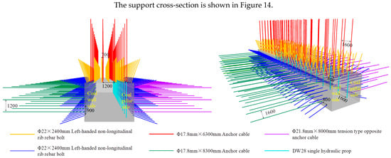
Figure 14.
Roadway support scheme and parameters.
Grouting: Ordinary Portland cement (grade 42.5 or higher) was used for grouting, with a water–cement ratio of 0.5:1 (by mass). Grouting holes were uniformly arranged in the middle of the coal pillar rib and 1 m below the roof, with a spacing of 4 m. The holes in the middle of the coal pillar rib were drilled perpendicular to the rib, while those 1 m below the roof were drilled at a 45° upward angle. The hole diameter was 50 mm, with a depth of 4 m. The grout diffusion range was designed to exceed 8 m, with the packer set 1.5 m from the hole bottom. Each hole was planned to inject 1 ton of grout, though the actual amount could be adjusted based on the consolidation effect. The final grouting pressure was controlled at approximately 7 MPa. If the pressure did not increase for an extended period, intermittent grouting was adopted, with intervals not exceeding 1 min, to achieve the desired modification effect on the narrow coal pillar.
5.3. Field Validation
The proposed collaborative control scheme—differentiated support (bolts and cables + swell-lock penetrating anchor cables + hydraulic props) combined with modification (coal pillar grouting + floor surface hardening)—was tested in the 51507 track gateway over a 100 m section. Monitoring and analysis of the surrounding rock deformation revealed that, after being affected by secondary mining, the deformation of the roof, floor, and ribs in the test section was less than 200 mm, as shown in Figure 15. Compared to previous conditions, the roadway deformation was significantly reduced, demonstrating effective surrounding rock control.
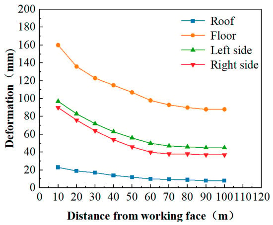
Figure 15.
Deformation amounts of the surrounding rock in the track gateway of the test section.
6. Results
- (1)
- Under the superimposed influence of goaf-side abutment pressure and secondary-mining-induced advance abutment pressure, the energy dissipation distribution in different zones of the retained roadway surrounding rock exhibits significant heterogeneity. The energy dissipation intensity decreases progressively with increasing distance from the roadway surface, demonstrating an asymmetric distribution pattern as follows: coal pillar rib > roof (coal pillar side) > solid coal rib > roof (solid coal side) > roof center > floor > floor (solid coal side) > floor (coal pillar side).
- (2)
- During secondary mining, the intense increase in energy dissipation and plastic zone expansion in thick coal seam narrow coal pillar roadways primarily occurs within approximately 10 m ahead of the working face. Severe energy dissipation in the narrow coal pillar leads to the interconnection of plastic zones in the roof, floor, and ribs, resulting in the failure of the load-bearing structure. The key to maintaining roadway stability lies in ensuring the stability of the narrow coal pillar while implementing targeted support for the ribs and their roof corners.
- (3)
- Based on the correlation between energy distribution and plastic zone evolution in narrow coal pillar roadways during secondary mining, the energy-driven mechanism of asymmetric failure is revealed: elastic strain energy accumulates in the stable rock mass at the plastic zone boundary, while the spatial distribution of dissipated energy shows high consistency with the plastic failure range. The asymmetric magnitude and orientation of energy dissipation induce asymmetric plastic zone propagation, ultimately leading to asymmetric deformation.
- (4)
- A synergistic control strategy combining differentiated support (bolts/cables + tension-type opposite anchor cables + hydraulic props) and material modification (pillar grouting + floor hardening) was proposed for narrow coal pillar roadways affected by secondary mining. This approach enhances the load-bearing capacity of narrow coal pillars. Industrial trials demonstrated effective control performance, with all roadway convergence measurements remaining below 200 mm.
Author Contributions
Conceptualization, K.L.; Methodology, K.L., Z.D., and J.F.; Software, K.L.; Validation, Z.D.; Formal Analysis, Z.D.; Investigation, J.F.; Resources, J.F.; Data Curation, M.J., A.M., and Z.J.; Writing—Original Draft, M.J. and Z.J.; Writing—Review and Editing, X.W. and Z.J.; Visualization, X.W.; Supervision, X.W. and A.M.; Project Administration, Z.D. and A.M.; Funding Acquisition, K.L. All authors have read and agreed to the published version of the manuscript.
Funding
This research was funded by the National Natural Science Foundation of China, the Science and Technology Innovation Fund of TianDi Science and Technology Co., Ltd., and the Science and Technology Development Fund of China Coal Research Institute, grant number 52474230, 2023-TD-ZD001-004, 2024JC-06.
Data Availability Statement
The original contributions presented in the study are included in the article; further inquiries can be directed to the corresponding author.
Conflicts of Interest
Authors Kun Lv, Zhigang Deng, Mingqi Jia, and Aoran Ma were employed by the company China Coal Research Institute. The remaining authors declare that the research was conducted in the absence of any commercial or financial relationships that could be construed as a potential conflict of interest.
References
- Wang, J.C.; Zhong, S.H. The present status and the key issues to be resolved of thick seam mining technique in China. J. Coll. Resour. Saf. Eng. 2008, 11, 829–834. [Google Scholar]
- Meng, H.D.; Tian, R.; Xu, Y.J. Study on reasonable width of narrow coal pillar for gob-side entry driving toward mining. Coal Eng. 2017, 49, 36–39. [Google Scholar]
- Meng, Q.R.; Wang, H.X.; Wang, P.F.; Chen, K.H.; Zhang, J.L.; Dong, E.Y.; Gao, X.; Hou, W. Gate road protection mechanism and surrounding rock control for gob-side entry with slender pillar in deep and inclined extra-thick coal seam. Coal Sci. Technol. 2024, 52, 38–52. [Google Scholar] [CrossRef]
- Yue, S.S.; Xie, S.R.; Chen, D.D.; Gao, M.M.; Zhang, Q.L.; Zhang, T. Research on surrounding rocks control of narrow pillar with high-intensity fully-mechanized top coal caving mining in 15 m ultra-thick coal seam. J. Min. Saf. Eng. 2017, 34, 905–913. [Google Scholar] [CrossRef]
- Jiang, W.; Ju, W.J.; Wang, Z.L.; Zhang, Z. Study on loading and deformation mechanism of gob-side roadway with thick and hard basic roofin fully mechanized top coal caving workface. J. Min. Saf. Eng. 2020, 37, 319–326. [Google Scholar] [CrossRef]
- Xu, Q.Y.; Huang, Q.G.; Hang, G.C. Fracture and instability mechanism and control technology of a narrow coal pillar in an entry in fully mechanized caving mining under intense effect mining. J. Min. Saf. Eng. 2019, 36, 941–948. [Google Scholar] [CrossRef]
- Ma, Q.; Liu, X.; Tan, Y.; Wang, Y.; Wang, R.; Wang, E.; Liu, X.; Zhao, Z.; Ren, D.; Xie, W.; et al. Monitoring and evaluation of disaster risk caused by linkage failure and instability of residual coal pillar and rock strata in multi-coal seam mining. Geohazard Mech. 2023, 1, 297–307. [Google Scholar] [CrossRef]
- Han, J.; Jia, D.; Hui, Q.; Cui, L.; Zhu, Z.; Cao, C. Unloading-slippage mechanism of coal bump in gate road of longwall. Geohazard Mech. 2023, 1, 208–217. [Google Scholar] [CrossRef]
- Zhang, B.S.; Wang, P.F.; Cui, S.Q.; Fan, M.Z.; Qiu, Y.M. Mechanism and surrounding rock control of roadway driving along gob in shallow-buried large mining height and small coal pillars by roof cutting. J. China Coal Soc. 2021, 46, 2254–2267. [Google Scholar] [CrossRef]
- Gu, C.W.; Wang, B.; Wang, J.; Lu, C.L. Research on bidirectional-reinforcement mechanism of narrow coal pillar of gob-side entry driving based on inflatable lock-type anchor. Coal Sci. Technol. 2022, 50, 106–116. [Google Scholar] [CrossRef]
- Zhao, H.B.; Liu, Y.H.; Liu, S.Q.; Zhang, J.H.; Wu, T. Instability mechanism of narrow coal pillar roadway floor considering dynamic load disturbance. Coal Sci. Technol. 2022, 50, 56–64. [Google Scholar] [CrossRef]
- Chen, Z.B.; Li, Y.L.; Yang, R.S.; Zhu, Y.; Lin, H.; Xiao, C.L. Non-uniform deformation mechanism and support technology of narrow coal pillar roadway. J. China Coal Soc. 2018, 43, 1847–1857. [Google Scholar] [CrossRef]
- Yang, K.; Gou, P.F. Differential control of surrounding rocks in high-intensity mining with double roadways. J. Min. Saf. Eng. 2021, 38, 76–83. [Google Scholar] [CrossRef]
- He, X.Y.; Ning, Z.X. Damage mechanism and control technology of mining roadway with large cross section and double roadway layout in deep mine. Saf. Coal Mines 2019, 50, 88–92. [Google Scholar] [CrossRef]
- Wang, C.L.; Yang, Y.L.; Liu, Y.L. Asymmetric deformation mechanism of soft rock roadway under repeated mining and the control technology. Coal Eng. 2023, 55, 45–51. [Google Scholar]
- Huang, W.P.; Zhao, T.Y.; Jiang, D.H.; Guo, X.S.; Zheng, Y.S.; Wang, X.W. Arrangement of double entry driving with a narrow coal pillar in the middle and stability control technology of surrounding rock. Chin. J. Rock Mech. Eng. 2023, 42, 617–629. [Google Scholar] [CrossRef]
- Wu, X.Y.; Liu, H.T.; Li, J.W.; Guo, X.F.; Lv, K.; Wang, J.Y. Space-time Evolutionary Regularity of Plastic Zone and Stability Control in Repetitive Mining Roadway. J. China Coal Soc. 2020, 45, 3389–3400. [Google Scholar] [CrossRef]
- Liu, H.T.; Han, Z.J.; Han, Z.; Huo, T.H.; Luo, M.; Luo, Z.L.; Peng, J.C.; Zhang, H.K. Mechanism of non-uniform expansion and stability control in surrounding rock failure zone due to superimposed mining. J. Min. Saf. Eng. 2024, 41, 522–532. [Google Scholar] [CrossRef]
- Chen, D.C.; Wang, X.Y.; Bai, J.B.; Li, M.L.; Lu, J.F.; Zhang, F.T.; Sun, S.Q.; Zhao, X.Q.; Yu, Y. The full cycle evolution law of energy-stress in the surrounding rock of the gob-side entry driving for adjacent advancing working face. Coal Sci. Technol. 2025, 53, 162–175. [Google Scholar]
- Liu, H.T.; Han, Z.; Chen, Z.H.; Han, Z.J.; Liu, Q.Y.; Zhang, H.K.; Zhang, D.D.; Liu, J.L. Research on energy evolution law and control method of deformation of high stress roadway surrounding rock. J. China Coal Soc. 2024, 49, 565–578. [Google Scholar] [CrossRef]
- Xie, S.; Wu, Y.; Chen, D.; Liu, R.; Han, X.; Ye, Q. Failure analysis and control technology of intersections of large-scale variable cross-section roadways in deep soft rock. Int. J. Coal Sci. Technol. 2022, 9, 19. [Google Scholar] [CrossRef]
- Wang, Z.; He, M.; Wang, Y.; Li, H. Dynamic process of rock avalanche and dynamic interaction between rock avalanche and hazard-bearing bodies. Arab. J. Geosci. 2021, 14, 2142. [Google Scholar] [CrossRef]
- Jiang, L.; Wu, Q.; Li, X.; Ding, N. Numerical simulation on coupling method between mining-induced stress and goaf compression. J. China Coal Soc. 2017, 42, 1951–1959. [Google Scholar] [CrossRef]
- Wang, M.; Song, Z.F.; Zheng, D.J.; Shen, W.L.; Gou, P.F.; Wei, S.J. Development and application of rock energy dissipation model in FLAC3D. J. China Coal Soc. 2021, 46, 2565–2573. [Google Scholar] [CrossRef]
- Meng, Q.B.; Xiu, X.K.; Song, Z.M.; Song, Y.; Cheng, Z.M.; Wang, C. The energy dissipation characteristics of surrounding rock during roadway excavation. J. Min. Saf. Eng. 2024, 41, 142–150. [Google Scholar] [CrossRef]
- Ding, K.; Gu, Q.H.; Wang, L.G.; Guo, J.X. Study on the Coal Rib Burst Mechanism in Deep Roadway and Energy Release. J. China Coal Soc. 2024, 49, 3759–3780. [Google Scholar] [CrossRef]
- Zhu, Y.; Yang, K.; Li, Y.L.; Li, W.Y.; Sun, H. Stability analysis and control strategy of layered floor of mining roadway under different coal pillar size. J. Min. Saf. Eng. 2023, 40, 467–479. [Google Scholar] [CrossRef]
- Fan, Z.Y.; Li, Y.L.; Sun, H.; Chen, X.L.; Huang, H.P. Characteristics and control measures of unsymmetric deformation of roadways within weakly-cemented soft rock. J. Min. Strat. Control Eng. 2022, 4, 44–53. [Google Scholar] [CrossRef]
Disclaimer/Publisher’s Note: The statements, opinions and data contained in all publications are solely those of the individual author(s) and contributor(s) and not of MDPI and/or the editor(s). MDPI and/or the editor(s) disclaim responsibility for any injury to people or property resulting from any ideas, methods, instructions or products referred to in the content. |
© 2025 by the authors. Licensee MDPI, Basel, Switzerland. This article is an open access article distributed under the terms and conditions of the Creative Commons Attribution (CC BY) license (https://creativecommons.org/licenses/by/4.0/).