Article

Design and Evaluation of Drilling Fluid Systems for Wellbore Stabilization During Drilling in Deep Coalbed Gas Reservoirs in the Ordos Basin

Oil Production Technology Research Institute of Yumen Oilfield Branch of China National Petroleum Corporation, Jiuquan 735000, China
*
Author to whom correspondence should be addressed.
Processes 2025, 13(10), 3150; https://doi.org/10.3390/pr13103150
Submission received: 14 August 2025 / Revised: 22 September 2025 / Accepted: 29 September 2025 / Published: 1 October 2025

Abstract

To overcome wellbore instability problems in deep coalbed gas reservoirs in the Ordos Basin, drilling fluid additives were evaluated and a drilling fluid system was designed. According to the SEM and CT analysis results, there were not only face and butt cleats in the coal rock but also bedding and layered fractures. Potassium chloride (KCl) and Potassium formate (HCOOK) drilling fluid systems were formulated. The recovery rate of shale and coal rock cuttings reached 99%, and the linear swelling rates for coal rock in both types of drilling fluid were less than 0.18%. Measured with a servo-controlled compression frame at a loading rate of 1 mm/min, the uniaxial compression strength of coal rock was 11.74 MPa, and it was 9.13 MPa and 10.35 MPa after immersion in KCl and HCOOK drilling fluid, respectively. This indicates that both systems have good inhibition properties. The invasion depth in packed sand was 15.5 mm for KCl drilling fluid and 8 mm for HCOOK drilling fluid, demonstrating good sealing performance by the systems. Compared to KCl drilling fluid, the HCOOK system exhibited better inhibition and sealing performance. After the removal of the 10 mm deep invasion section of drilling fluid, the permeability of the coal rock recovered by more than 90%, and the drilling fluid caused minimum damage to the reservoir. The optimized drilling fluid exhibits excellent sealing and inhibition capabilities, making it highly effective in addressing wellbore stability challenges in carbonaceous mudstone formations at 4000 m in depth in the deep coalbed methane reservoirs of the Ordos Basin.

1. Introduction

Coalbed hydrocarbon gases represent one of the most significant unconventional energy resources [1,2]. Since the 1990s, coal seams at shallow depths have been the main target zone for natural gas exploration and exploitation. With the substantial rise in energy demands all over the world, coal strata deeper than 1500 m have attracted more and more attention [3,4]. Deep coal seams exhibit a high gas content, typically ranging from 10 m3/t to 33 m3/t [5,6,7]. To enhance the development of coalbed natural gases, drilling directional and horizontal wells has become a common approach. However, extensive cleats or fractures in coalbeds can result in them exhibiting brittle and mechanically weak properties. These wells tend to demonstrate wellbore instability problems during drilling operations [8,9]. To tackle these problems, wellbore-stabilized drilling fluid has emerged as an effective and economical approach [10,11,12].
Oil-based drilling fluid can be applied due to its excellent ability to reduce swelling and dispersion in shale. However, serious environmental concerns and high operational costs represent major obstacles in its application [13]. Instead, the drilling industry tends to use water-based drilling fluid with chemical inhibitors to stop shale hydration swelling and maintain wellbore stability, as shown in Figure 1. Over the decades, various categories of inhibitors have been developed, synthesized, and applied in oil fields [10,14,15]. Simple salts such as KCl or HCOOK are widely used as inhibitors. Potassium ions (K+) can enter the interlayer spaces between individual montmorillonite clay crystals, making it difficult for water to penetrate into the interlayer spaces and resulting in a weak expansion capacity [16,17], as shown in Figure 1. The most common potassium-based drilling mud is potassium chloride. Potassium drilling mud generates hydrostatic pressure to prevent borehole collapse, interacts with clay minerals to minimize swelling, withstands high temperatures, and has a favorable environmental impact, thereby leading to more efficient drilling operations. Overall, the use of potassium drilling mud significantly contributes to efficient and safe drilling operations [18]. Potassium formate reagents can be used to adjust the properties of technical fluids, with the following functions, among others: inhibiting unstable clay rocks and improving borehole stability; enhancing the thermal stability of polymers, as well as technical fluids, under high temperatures; increasing the density of technical fluids and reducing solid content; reducing the negative environmental impact compared to commonly used chlorides in technical fluids (KCl, NaCl, CaCl2); and improving the lubricating properties of technical fluids, making them suitable for wells with large inclination angles [19]. Polymers such as polyacrylamide (PAM) and partially hydrolyzed polyacrylamide (PHPA) are also superior inhibitors and can form a protective film over the surface of clay particles, thus reducing water absorption and shale swelling. In addition, shale cutting particles can be encapsulated by the long polymer chains so that the cuttings remain at a low dispersion after strong grinding during mud circulation [10,14,15]. Building on our improved understanding of crystalline swelling in shale, low-molecular-weight polymetric shale inhibitors were developed. Polymeric alcohol acts by adhering to the surface of clay crystal layers to reduce water adsorption [20,21,22]. Cloud points enable the polymeric alcohol particles to block microscale pores and fractures, meaning that water penetration can be reduced [20]. Another new type of amine-terminated polyether shale inhibitor has been developed and used to formulate a high-performance water-based drilling fluid [23,24,25,26,27,28]. This amine-terminated polyether inhibitor has demonstrated better shale inhibition than traditional inhibitors. The reduction in water adsorption by clay minerals caused by the amine-terminated polyether inhibitor helps to improve the wellbore stability of drilling fluid. Moreover, when the amine-terminated polyether inhibitor is used together with KCl, the synergistic function of both inhibitors can control both crystalline swelling and osmotic swelling in shale [23].
The Ordos Basin is a large sedimentary basin characterized by multi-cycle evolution and diverse sedimentary types. In the Benxi Formation of the Ordos Basin, the predominant rock types consist of coal seams, gray-black mudstone, and carbonaceous mudstone, with dark gray sandstone and ferruginous–aluminous mudstone occurring at the base. The coalbed generally has the characteristics of low strength and poor wellbore stability. The coalbed well section is prone to collapse, and there is a high risk of drilling pipes and casing tubing sticking. To minimize drilling problems in this section, high-performance, wellbore-stabilized drilling fluid systems were formulated and evaluated. For a comparative study, two types of drilling fluid, KCl and HCOOK polymer drilling fluid, were evaluated.

2. Materials and Methods

2.1. Materials

Coal rock and shale samples were collected from the Benxi Formation; the composition of the rock is given in Table 1. Shale was composed of 53.15% quartz and 35% clay minerals, and the remainder comprised other types of minerals. Of the clay minerals, kaolinite was the most common, and shale contained 6.3% illite and 4.2% illite/montmorillonite interbedded mineral. Coal rock contained 70% coal, 17.89% quartz, and 6.16% kaolinite. Drilling fluid additives were provided by the oil field.

2.2. Methods

2.2.1. Structural Characterization

Scanning electron microscopy (SEM) enables the observation of pore-throat characteristics, mineral types, and distribution patterns in clay minerals on a finer scale. This experiment was conducted in accordance with the Chinese petroleum industry standard SY/T 5162-2014 “Analytical Method of Rock Samples by Scanning Electron Microscope” [29]. The instrument used was the Nova Nano SEM 450 (Thermo Fisher Scientific Inc., Waltham, MA, USA).
During the experiment, the Mitaka Nano Voxel 5000 series micro-CT scanner (Tianjin Sanying Precision Instrument Co., Ltd., Tianjin, China) was employed as a state-of-the-art imaging tool, enabling the non-destructive high-resolution 3D visualization of samples. The sample was secured on a metal fixture mounted onto a rotational stage via a ball-and-socket joint. Through irradiation from a micro-focus X-ray source (Tianjin Sanying Precision Instrument Co., Ltd., Tianjin, China), X-rays penetrated the sample to capture density information, which was then projected onto a detector (Tianjin Sanying Precision Instrument Co., Ltd., Tianjin, China). The photosensitive components of the detector converted this information into visual data. Image acquisition from multiple angles was reconstructed using software (Avizo 2019.1) to generate a composite 3D image. The scanner maintained high pixel resolution and provided accurate quantitative analysis. Pixel resolution reflects the physical size represented by a single pixel in the CT image, while spatial resolution denotes the scanner’s ability to distinguish finely separable geometric details in the image [30].

2.2.2. Drilling Fluid Performance Evaluation

The test methods included in this study were chosen according to API standards (API RP13B-1) [31].
(1)
Rheology of drilling fluid
Rotational viscometers are used to determine flow characteristics. Figure S1 shows the 6-Speed (3 rpm, 6 rpm, 100 rpm, 200 rpm, 300 rpm, and 600 rpm) rotational viscometer used in this study. Drilling fluid was poured into the cup. We controlled the rotation of the outer sleeve of the 6-Speed and recorded the value of the dial. The Bingham Plastic model is commonly used to characterize drilling fluid rheology. The plastic viscosity (PV) and yield point (YP) values are determined according to the Bingham Plastic model using the formulas in Equations (1) and (2):
Apparent Viscosity (AV) = Φ600/2
Plastic Viscosity (PV) = Φ600 − Φ300
(2)
Drilling fluid filtration property
Fluid loss, also known as API filter loss, was measured with the device shown in Figure S2. Firstly, drilling fluid was poured into the slurry cup, and the top cover, along with filter paper, was fixed via pressing with a screw rod. We then connected the cup to the gas source and applied a pressure of 100 psi to the mud. The amount of mud that had passed through the filter paper after 30 min at room temperature was recorded. A high-temperature, high-pressure filter loss test device, shown in Figure S3, was used to measure the volume of drilling fluid filtration loss through filter paper after 30 min at a differential pressure of 3.5 MPa and a temperature of 120 °C. The test procedures were the same as those of API for filter loss, and the mud was deposited in the slurry cup, which was placed in a heating component and connected to the air source. When the temperature reached the setting value, 3.5 MPa gas pressure was applied to the mud, and the filtration after 30 min was recorded.
(3)
Drilling fluid lubricity
To characterize the friction between the drilling pipe and casing tubing, the friction coefficient of the drilling fluid between two metal surfaces was measured with the device shown in Figure S3. The friction coefficient μ was defined as follows:
μ = F/W
F is the friction force, while W is the load perpendicular to the contact surface.
To characterize the friction between the drilling pipe and the wellbore with the mud cake, the friction coefficient between the metal block surface and the mud cake was tested with the device shown in Figure S4. Under the tilted workbench, the slide block placed on the mud cake exerted a downward force to play the role of gravity, meaning that it would begin to slide after overcoming the sticking force. The friction coefficient μ can be calculated according to Equation (3).
(4)
Inhibition capability
Hot rolling recovery and linear swelling tests were conducted to characterize the inhibition performance of drilling fluid. Coal or shale rock samples were broken down to cuttings of 2–6 mm in size. Cuttings of 50 g in weight were placed in a hot rolling tank (shown in Figure S3) filled with drilling fluid. After hot rolling at 80 °C for 16 h, cuttings were recovered with a 40-mesh sieve. The recovery rate could be calculated by dividing the weight of recovered cuttings by 50 g.
The ZNP-1 device (shown in Figure S4) was used to measure the linear swelling rate. Artificial cores were prepared via the compression of shale or coal powders with a size less than 0.154 mm in a cylinder mold for 15 min under 20 MPa. The synthetic cores were placed in the device and, after immersion in drilling fluid, time-dependent swelling displacements were recorded. Then, the linear swelling rate could be calculated by dividing the swelling displacement increments by the initial thickness of the core samples.
(5)
Sand packing filtration loss test
The instrument used for this test, shown in Figure S5, was a non-permeable filtration loss tester with a pressure difference of 100 psi. We deposited the sand in the transparent cylindrical body in the bottom part of the instrument and then poured drilling fluid into the cylindrical body in the upper part. We connected the air source and adjusted the pressure on the drilling fluid to 100 psi. We observed the penetration of drilling fluid through the cup and measured the filtration loss after 30 min.
(6)
Uniaxial compression strength test
The uniaxial compression strength of the rock was measured before and after immersion in drilling fluid using the servo hydraulic test system (HMTC-1) in the Laboratory of Rock Mechanics (Changzhou University, Changzhou China). The loading rate in the experiment was 0.1 mm/min.
(7)
Reservoir damage test
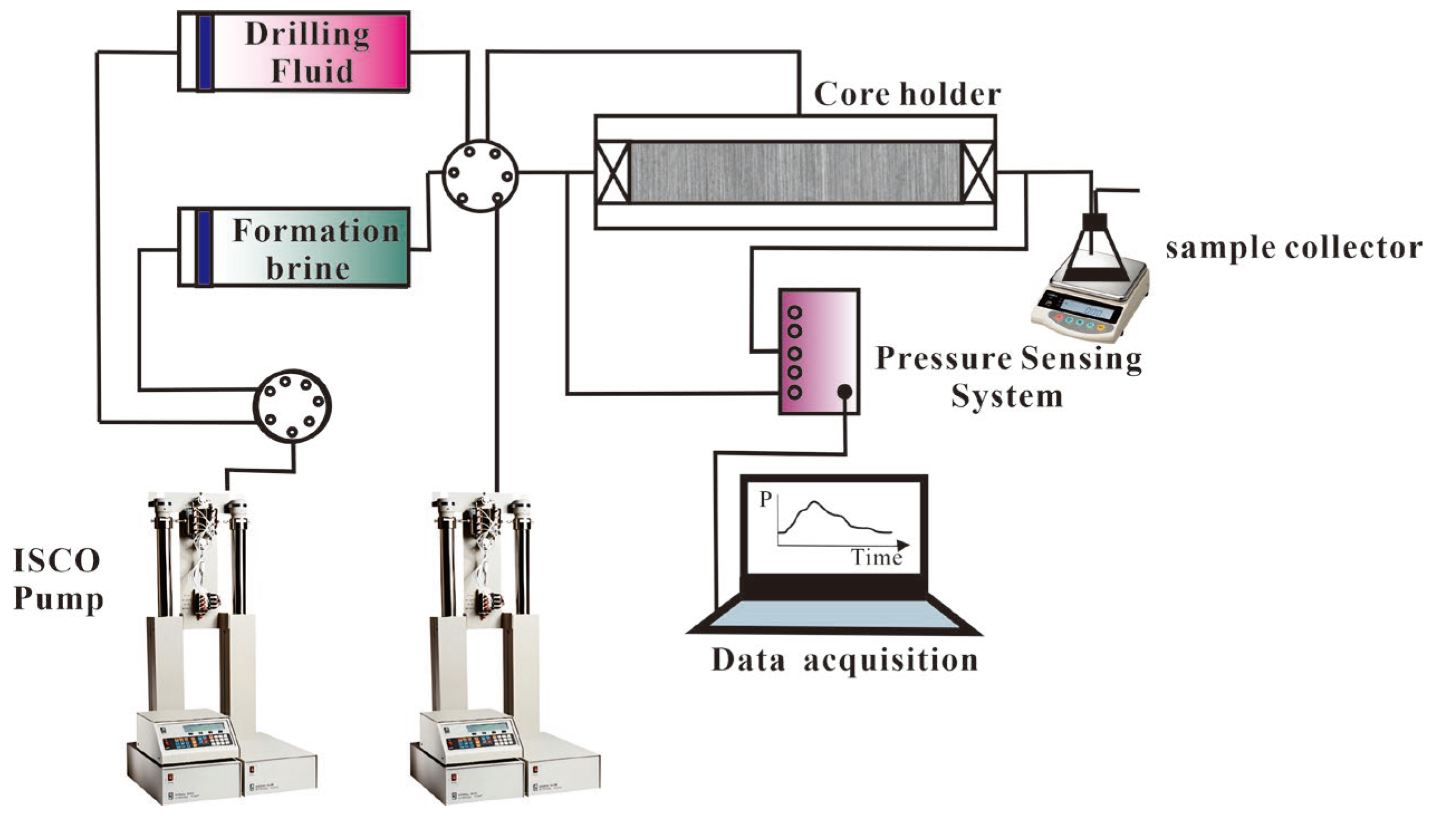
Permeability is an important factor affecting coalbed natural gas production, and the permeability before and after drilling fluid invasion was measured to evaluate the damage to the coalbed gas reservoir. The core was placed in a core holder with a confining pressure of 2.0 MPa applied. Formation brine was injected through an ISCO pump at the top end of the core at a flow rate of 2 mL/min. The data acquisition system was monitored until the pressure stabilized, at which point the pressure difference across the core was recorded. The mass of fluid discharged from the bottom end of the core over a specified period was measured to determine the flow rate through the core. The permeability (K0) was calculated using Darcy’s law. Subsequently, the formation brine at the top end was replaced with the drilling fluid to be tested. A flow pressure of 0.5 MPa was applied for 2 h to conduct dynamic contamination. After contamination, the core was dried, and the permeability after exposure to the drilling fluid (K1) was measured using the formation brine. The permeability displacement procedure is shown in Figure 2.
k = Q μ L A Δ p
In this formula, k represents the rock liquid permeability, 10−3 µm2; Q denotes the volume of fluid passing through the rock sample per unit time, cm3/s; μ is the fluid viscosity, mPa·s; L indicates the length of the rock sample, cm; A refers to the cross-sectional area of the rock sample, cm2; and Δp represents the pressure difference across the rock sample, MPa.

3. Results and Discussion

3.1. Structural Characterization

3.1.1. Shale Sample Surface Morphology

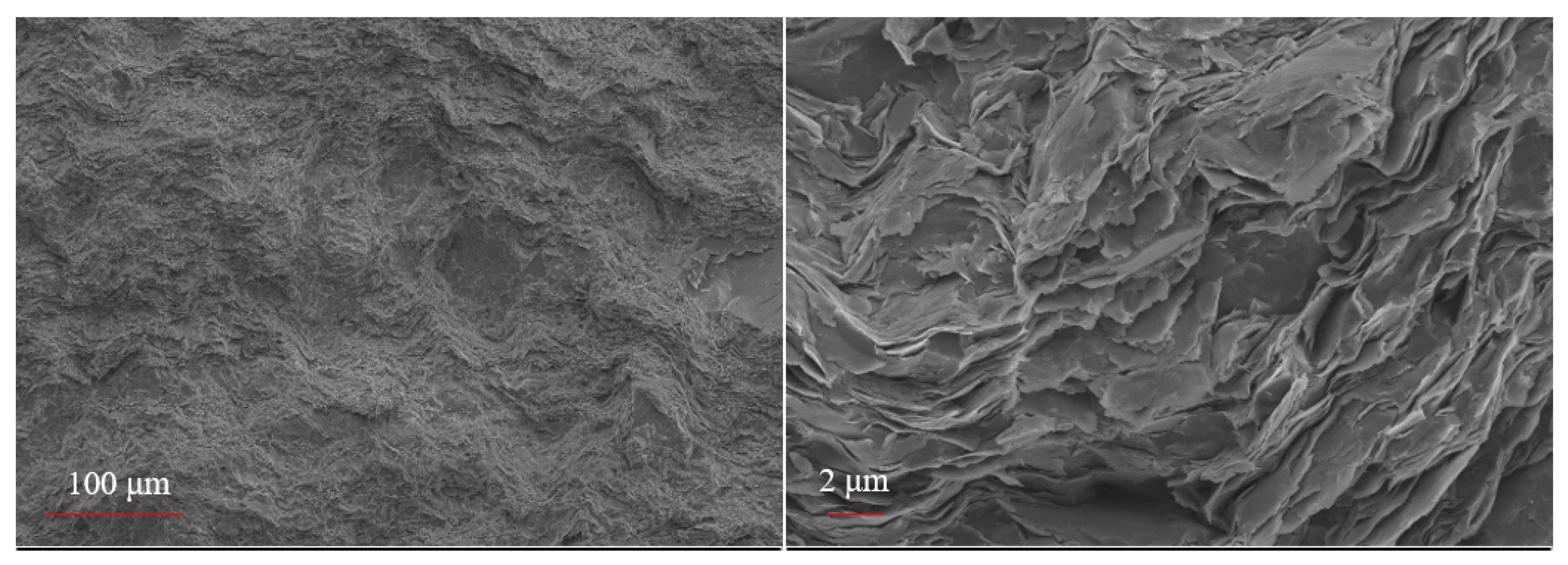
As shown in Figure 3, no obvious bedding planes or microcracks can be observed in the shale. The layered structures of minerals such as kaolinite, illite, and illite/montmorillonite interbedded mineral can be observed.

3.1.2. Coal Rock Sample Surface and Cross-Sectional Morphology

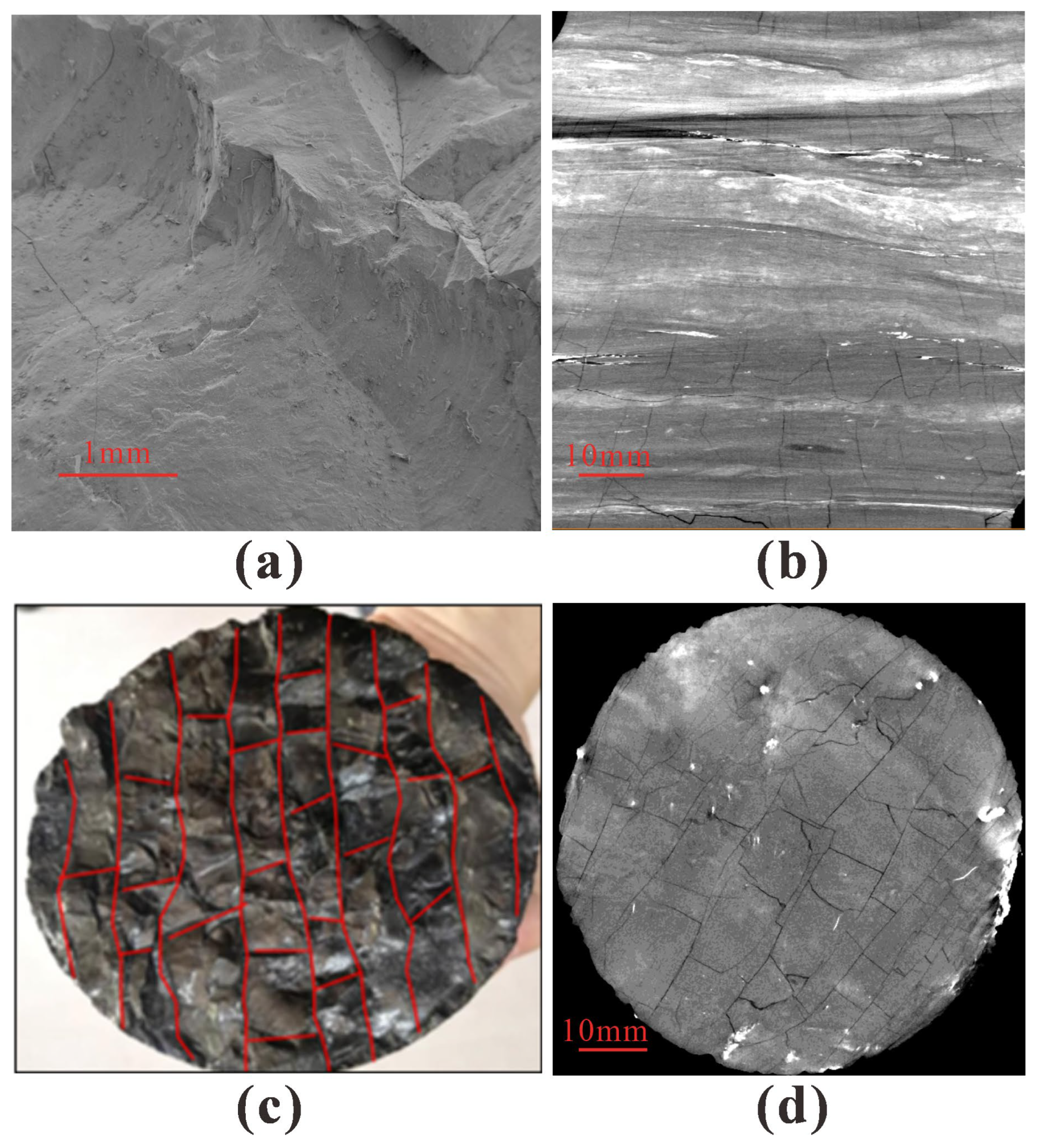
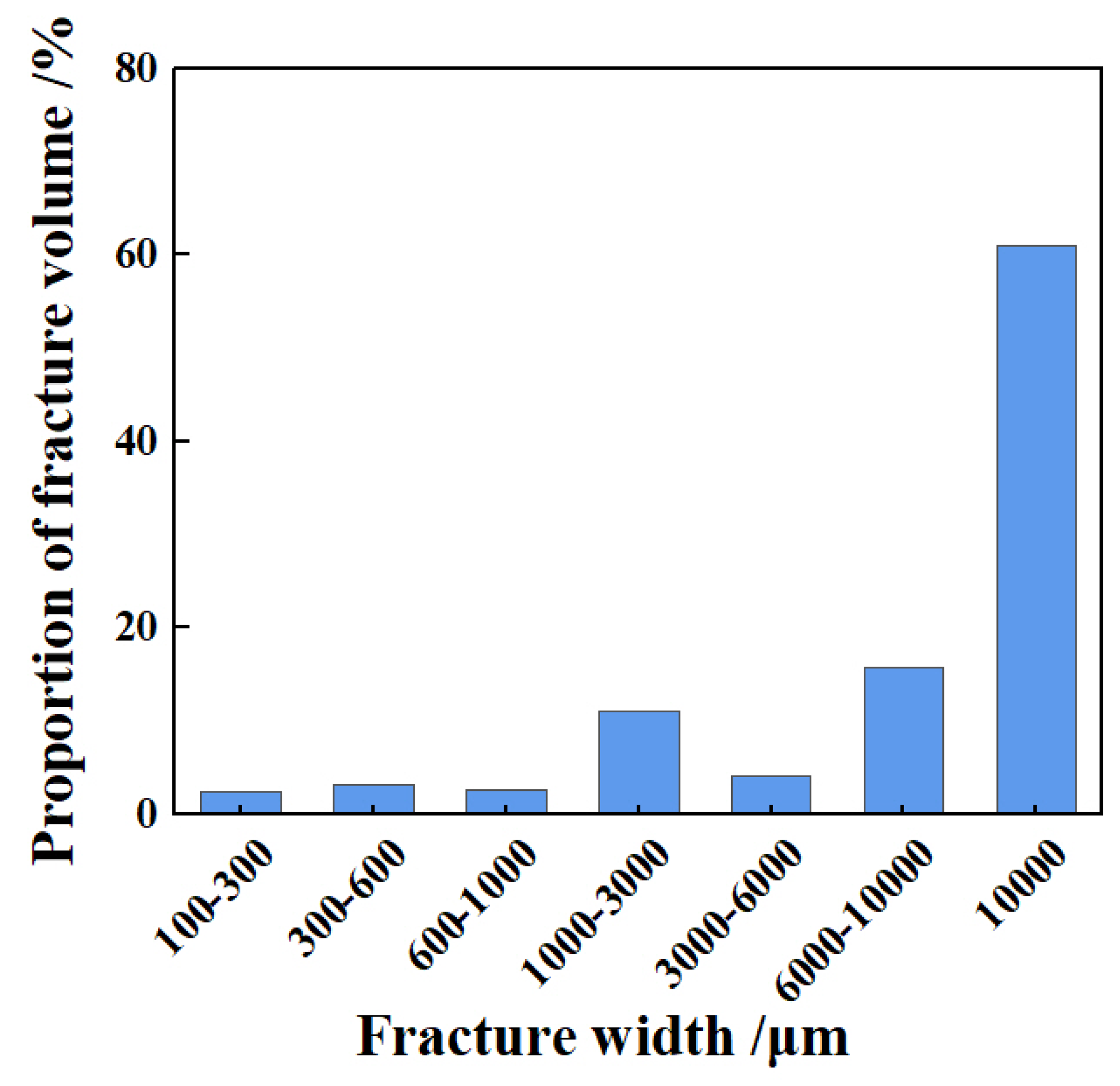
As shown in Figure 4a,c,d, at the xy cross-sections, both face and butt cleats were highly developed, and secondary cleats intersected the main parallel cleats. This network pattern can induce good connectivity and poor mechanical properties in coal rock. At the xz cross-sections (Figure 4b), obvious bedding and layered fractures can be observed. According to Figure 5, the fracture width ranged from 100 μm to 100,000 μm. Cleavage contributed to the smaller fractures, while major fractures mainly existed between beddings.

3.2. Evaluation and Selection of Drilling Fluid Agents

3.2.1. Inhibition and Coating Agents

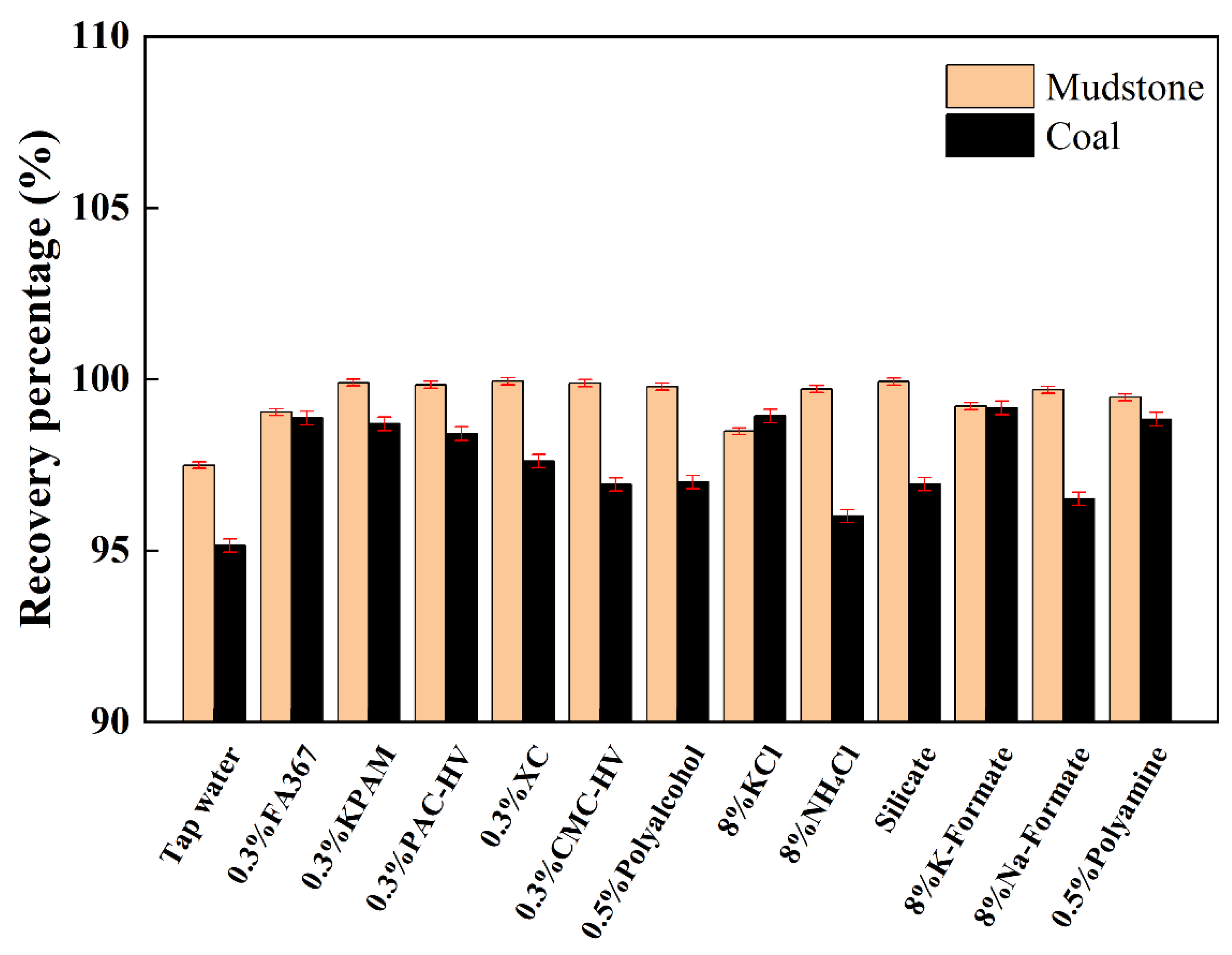
To enable the successful drilling of shale or coal methane sections that cause serious wellbore stability problems, the ionic inhibition agent, low-molecular-weight polymer inhibition agent, and high-molecular-weight polymer coating agents were selected and evaluated. As shown in Figure 6, among the ionic inhibition agents, KCl and HCOOK exhibited the highest recovery rates for both shale and coal rock cuttings. PA was more effective as a low-molecular-weight polymer inhibition agent than polyalcohol. KPAM maintained a high recovery rate through its polymer chains coating the cutting surface. According to Zhang et al., PA has a synergistic effect with KCl; K+ can exchange cations with clay minerals, while PA can be adsorbed into the surface of clay minerals. As a result, both osmotic hydration swelling and surface hydration are inhibited. To create a drilling fluid with better inhibition performance, KCl and PA can be used together to formulate drilling fluid systems [26,27].

3.2.2. Filtration Reducer

To reduce drilling fluid filtration from the wellbore to the coal formation, as shown in Figure 1, a filtration reducer and sealing agents were selected. Two base mud systems were formulated as base mud 1a and 1b (Table 2). KCl and PA were used as inhibition agents in 1a, and HCOOK was the inhibition agent in 1b. The filtration reducers were added into the base mud via high-speed agitation. Fluid loss experiments were conducted before and after hydrothermal aging at 120 °C for 16 h, and the filtration fluid volume is shown in Figure 7. In the KCl mud system, KPAM, M-SMC, NPAM, and SPNH were optimal, while in the HCOOK system, KPAM, PAC-LV, SPNH, and NPAN showed superior results.

3.2.3. Sealing Agent

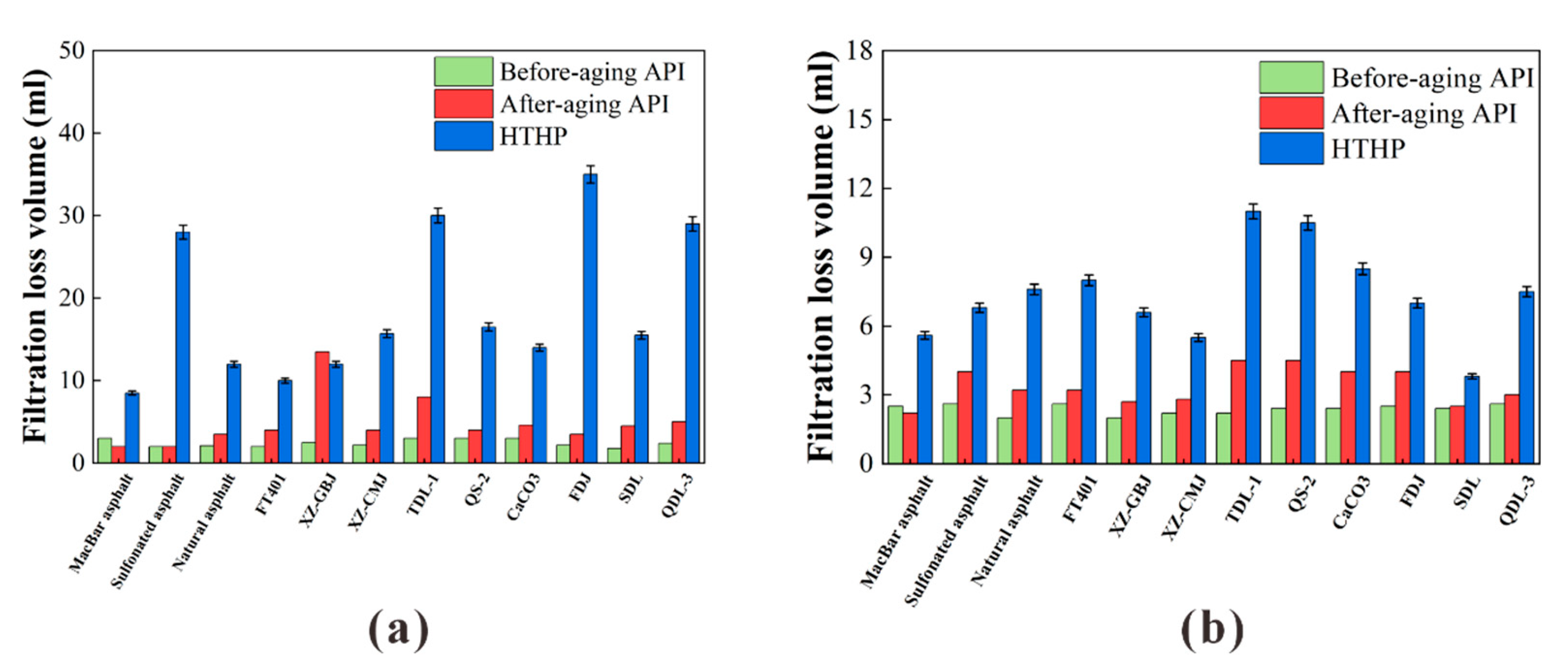
Through the addition of the optimal filtration reducer into base mud 1a and 1b, base mud 2a and 2b (Table 2) were designed. After the addition of various categories of sealing agent, the base mud was placed in a hot rolling tank and hydrothermally aged at 120 °C for 16 h. The API filtration loss and HTHP filtration loss were measured. As can be observed in Figure 8, in the KCl mud system, among asphalt samples, the MKB and FT401 types led to less filtration loss, and XZ-GBJ and CaCO3 were optimal sealing particles. In the HCOOK system, MKB asphalt and sulfonated asphalt exhibited better performance, and XZ-CMJ and SDL were the most effective sealing particles [30,31].

3.2.4. Lubrication Agent

With the optimal seal agents, base mud 3a and 3b (Table 2) were designed. After the lubrication agent was added, the friction coefficients between the two metal surfaces immersed in drilling fluid and between the metal surface of the metal block and the mud cake were measured, respectively. As shown in Figure 9, PGCS-1 was the best lubricant for both mud systems. The graphite type of lubricant could function better than white oil in the KCl system, while in the HCOOK system, similar friction coefficients were observed for the two lubricants.

3.2.5. Optimization of Drilling Fluid System

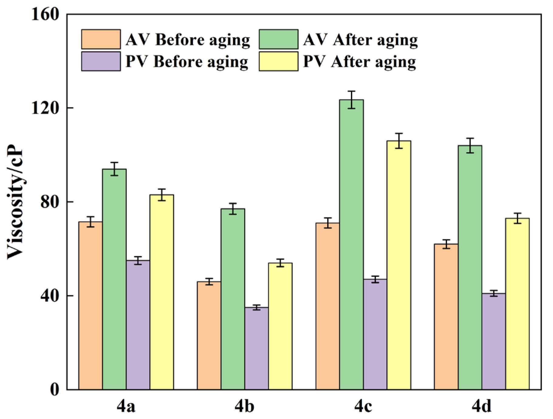
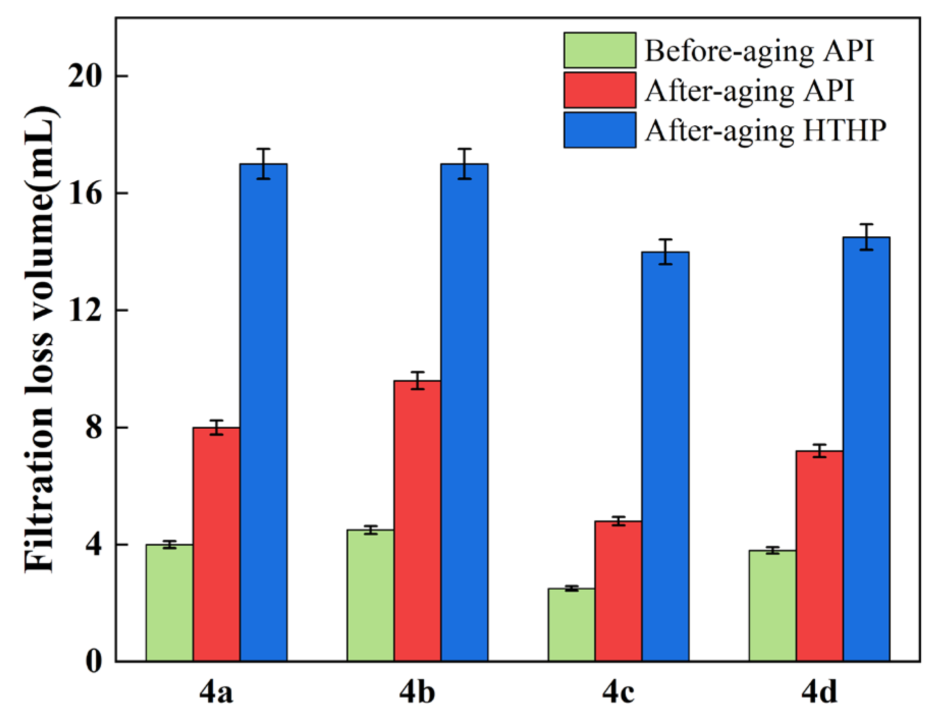
With the optimal lubrication agent, the KCl and HCOOK drilling systems were designed as 4a, 4b, 4c, and 4d. The apparent viscosity (AV), plastic viscosity (PV), and filtration loss volume of the four formulations were tested before and after aging. As shown in Figure 10, formulations 4a and 4c were KCl drilling systems. Before aging, 4a exhibited the highest AV value, while after aging, 4c showed the highest AV value, with an increase of 73.9%. Before aging, 4a had the highest PV value, and after aging, the PV values of 4a and 4c were 83 cP and 106 cP, respectively. Formulations 4b and 4d were HCOOK drilling systems. Both before and after aging, 4d demonstrated the highest AV and PV values among them. Figure 11 presents the filtration loss volumes of the drilling fluid systems. For the KCl drilling systems, formulation 4c showed the lowest API filtration loss both before and after aging, with values of 2.5 mL and 4.8 mL, respectively. Its high-temperature, high-pressure (HTHP) filtration volume after aging was 14 mL. Among the HCOOK drilling systems, formulation 4d exhibited the lowest API filtration loss both before and after aging, with values of 2.5 mL and 4.8 mL, respectively. Its HTHP filtration volume after aging was 14.5 mL. Therefore, formulations 4c and 4d were selected as the optimized systems for the KCl and HCOOK drilling systems, respectively, in this study.

3.3. Evaluation of Optimized Drilling Fluid System

3.3.1. Drilling Fluid Contamination Test

After the addition of 10% or 15% KCl, a lower API filtration volume was observed for KCl drilling fluid, and a slight decrease in AV and PV occurred (Figure 12a1). With the addition of 5% or 10% soil, the API filtration volume decreased, while the AV and PV slightly increased [30]. With HCOOK drilling fluid, an increase in API filtration volume was observed, while the AV and PV decreased, after adding 10% or 15% KCl. With 5% soil, the AV, PV and API filtration volume all increased. When the soil content was 10%, the AV increased sharply, and after aging, it eventually exceeded the maximum range of the viscometer (300 cp). This shows that KCl drilling fluid can demonstrate good rheology and filtration performance with 15% KCl or 10% soil contamination, while HCOOK drilling fluid can remain stable with the addition of 15% KCl or 5% soil.

3.3.2. Sand Packing Filtration Test

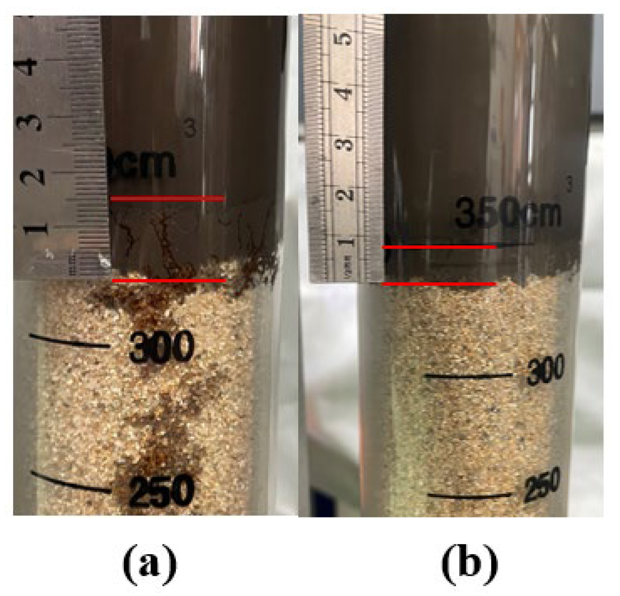
As shown in Figure 13, the invasion of drilling fluid into packed sand can be observed. The invasion depth in the KCl polymer system was 15.5 mm, while the depth in the HCOOK polymer system was 8.0 mm, indicating that both systems can effectively block pore spaces in the packed sand and that the HCOOK polymer system achieves a superior sealing performance.

3.3.3. Inhibition Performance Test

As shown in Figure 14a, the linear swelling rate of the coal sample was 0.30%, and in KCl and HCOOK drilling fluid, this rate decreased to 0.18% and 0.14%, respectively. The recovery rate of coal rock cuttings was 95.14% in water and reached 99.30% in both drilling fluid systems (Figure 14b) [32,33]. Hence, both systems showed good performance in inhibiting swelling and dispersion in coal rock samples. As observed in Figure 14c, the uniaxial compression strength was 59.85 MPa for shale core and 11.74 MPa for coal rock. After immersion in KCl drilling fluid, the shale core strength was reduced to 52.89 MPa and the coal rock strength was 9.13 MPa. On the other hand, in HCOOK drilling fluid, a similar strength reduction was observed for the shale core, while the coal rock strength was 10.35 MPa, indicating that HCOOK drilling fluid is more able to reduce strength damage [34,35].

3.3.4. Reservoir Damage Evaluation

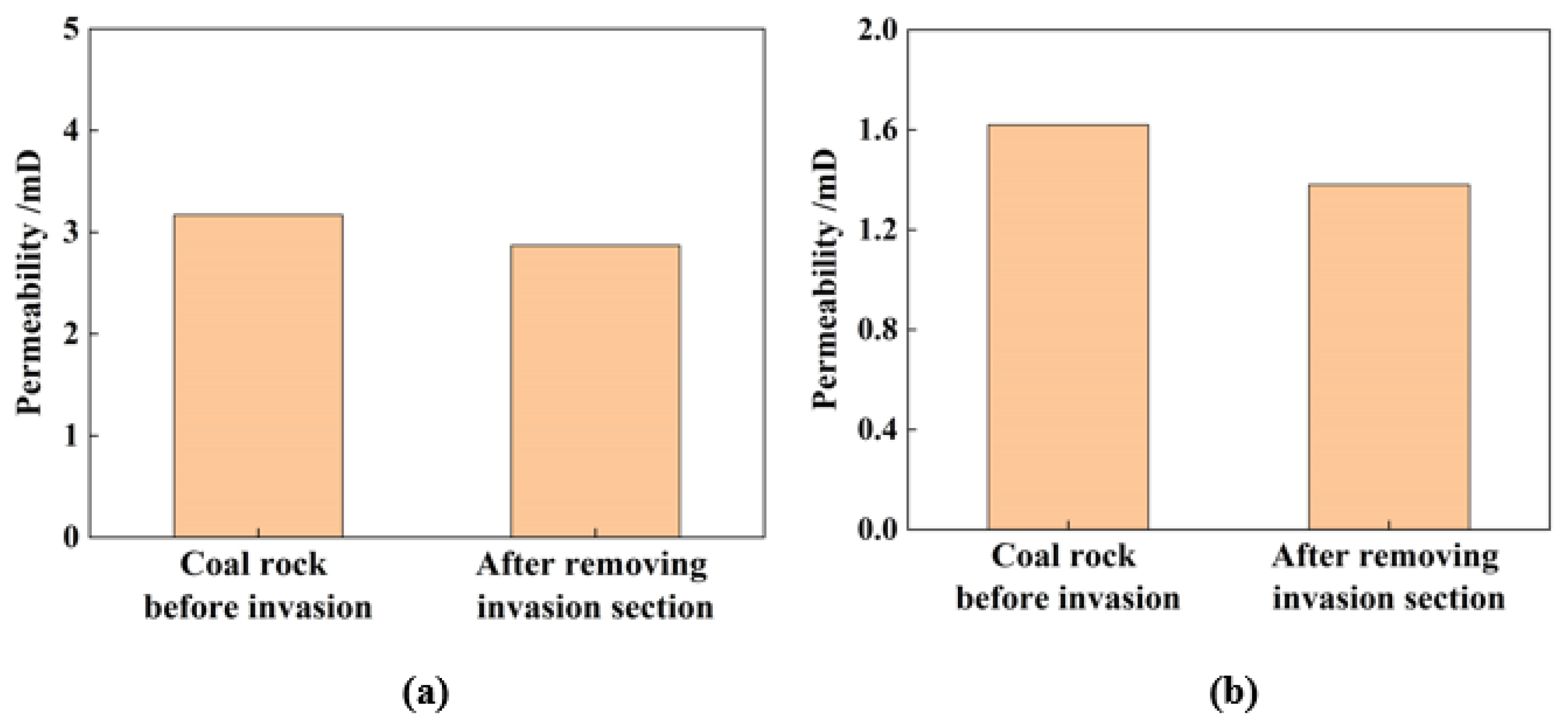
The permeability of coal rock was measured first, and then drilling fluid was injected into the rock core surface at a pressure differential of 1 MPa for 24 h. Then, after removing 10 mm of the invasion section at the drilling fluid injection end, the coal rock permeability was measured again, and the results are shown in Figure 15. Before the invasion, the core permeability was 3.17 mD, and after the invasion and removal of the injection section, the permeability was 2.87 for KCl drilling fluid, showing a recovery of 90.5%. The core permeability was 1.62 mD, and it recovered by 90.0% to 1.38 mD with HCOOK drilling fluid. These results indicate that neither drilling fluid system would cause significant damage to the reservoir’s permeability [36,37].
Compared to existing drilling fluid technologies, the optimized drilling fluid system enables an enhanced rate of penetration, significantly reduces the time required to address bit balling and reaming operations, and lowers waste generation per unit hole volume [38,39]. These improvements can lead to substantial savings in both drilling and waste disposal costs. Potassium formate has high solubility and can be prepared in the form of high-density solutions [40,41]. As a result, the total weight per transport load is greater, leading to higher transportation costs [42,43]. However, for high-risk wells, deepwater wells, and environmentally sensitive areas, choosing a potassium formate-based drilling fluid is often a more economical option in terms of the overall cost [44,45].

4. Conclusions

To help maintain the wellbore stability of deep coalbed natural gas reservoirs in the Ordos Basin, the optimal drilling agents were selected and drilling fluid systems were designed. The following conclusions can be drawn:
(1)
Shale is mainly composed of quartz, kaolinite, illite, and illite/montmorillonite interbedded mineral, and coal rock contained coal, quartz, and kaolinite. No obvious bedding or microcracks were observed in the shale, and a layered structure of minerals could be observed. The fracture width in coal rock ranged from 100 μm to 100,000 μm. Cleavage contributed to the smaller fractures, while major fractures mainly existed between beddings.
(2)
With the optimal drilling agents, KCl and HCOOK polymer drilling fluid systems were designed. The two systems show good inhibition performance, with the recovery rate of shale cuttings reaching more than 99.0%, while the linear swelling rate can be controlled at less than 0.18%. Both systems demonstrate superior sealing performance, and the invasion depth was less than 15.5 mm during the packed sand filtration loss test. Coal rock permeability was recovered by more than 90.0% after the removal of 10 mm of the invasion section, indicating that the drilling fluid does not cause significant damage and can protect deep coalbed gas reservoirs.
(3)
Compared to the KCl system, the HCOOK drilling fluid system shows better inhibition and sealing capacity. The uniaxial compression strength reduced from 11.74 MPa to 10.35 MPa after immersion in HCOOK drilling fluid, whereas it decreased to 9.13 MPa in KCl drilling fluid. The invasion depth in packed sand was only 8.0 mm for HCOOK drilling fluid, whereas it was 15.5 mm for KCl drilling fluid. As a result, the HCOOK drilling fluid system is more suitable for addressing wellbore collapse problems in deep coalbed gas reservoirs in the Ordos Basin. In future studies, the proposed formulation will be applied in field operations, and the results will be compared with laboratory data to improve the entire drilling fluid system, thereby enabling the resolution of practical drilling engineering problems.

Supplementary Materials

The following supporting information can be downloaded at: https://www.mdpi.com/article/10.3390/pr13103150/s1, Figure S1: The rotational viscometer with 6-Speed; Figure S2: API filtration test device; Figure S3: High temperature high pressure filter loss test device; Figure S4: ZNP-1 device; Figure S5: Non-permeable filtration loss tester with a pressure difference of 100psi; Figure S6: Hot rolling device; Figure S7: Friction Coefficient Tester; Figure S8: Lubrication test device.

Author Contributions

Methodology, G.C.; Validation, C.Z. and J.Z.; Investigation, Z.L., L.B. and P.Z.; Resources, H.M.; Data curation, D.C.; Writing—original draft, X.Z. (Xin Zhou); Writing—review and editing, X.Z. (Xinchen Zhang). All authors have read and agreed to the published version of the manuscript.

Funding

This work was financially supported by China Petroleum Yumen Oilfield Branch Science and Technology Project “Key Technology Research and Field Testing in New Exploration Fields of Yumen Exploration Area”—Project 1 “Research on Drilling and Completion Technology of Horizontal Wells in Ningqing Deep Coal Rock Gas Block” (YM2025-006-01).

Data Availability Statement

The original contributions proposed in this study are included in the article and Supplementary Materials. If you have further questions, please contact the corresponding author.

Conflicts of Interest

All authors were employed by the Oil Production Technology Research Institute of Yumen Oilfield Branch of China National Petroleum Corporation. The Oil Production Technology Research Institute of Yumen Oilfield Branch of China National Petroleum Corporation had no role in the design of the study; in the collection, analyses, or interpretation of data; in the writing of the manuscript, or in the decision to publish the results.

References

  1. Rightmire, C.T.; Eddy, G.E.; Kirr, J.N. Coalbed Methane Resources of the United States; American Association of Petroleum Geologists: Tulsa, OK, USA, 1984. [Google Scholar]
  2. Bao, Y.; Wei, C.; Neupane, B. Generation and accumulation characteristics of mixed coalbed methane controlled by tectonic evolution in Liulin CBM field, eastern Ordos Basin, China. J. Nat. Gas Sci. Eng. 2016, 28, 262–270. [Google Scholar] [CrossRef]
  3. Qin, Y.S.; Yang, S.Z. Accumulation effects and coupling relationship of deep coalbed methane. Acta Pet. Sin. 2012, 33, 48. [Google Scholar]
  4. Qin, Y.; Shen, J. On the fundamental issues of deep coalbed methane geology. Acta Pet. Sin. 2016, 37, 125. [Google Scholar]
  5. Niu, X.; Fan, L.; Yan, X.; Zhou, G.; Zhang, H.; Jing, X.; Zhang, M. Enrichment conditions and resource potential of coal-rock gas in Ordos Basin, NW China. Pet. Explor. Dev. 2024, 51, 1122–1137. [Google Scholar] [CrossRef]
  6. Li, J.; Cao, H.; Li, X.; Liu, H. Characteristics of coalbed methane resource and the development strategies. Nat. Gas Ind. 2009, 29, 9–13. [Google Scholar]
  7. Song, Y.L.; Qin, S. Geochemical characteristics and genesis of coalbed methane in China. Acta Pet. Sin. 2012, 33 (Suppl. S1), 99. [Google Scholar]
  8. Zhao, H.; Chen, M.; Li, Y.; Zhang, W. Discrete element model for coal wellbore stability. Int. J. Rock Mech. Min. 2012, 54, 43–46. [Google Scholar] [CrossRef]
  9. Gentzis, T.; Deisman, N.; Chalaturnyk, R.J. Effect of drilling fluids on coal permeability: Impact on horizontal wellbore stability. Int. J. Coal Geol. 2009, 78, 177–191. [Google Scholar] [CrossRef]
  10. Li, Q.; Zhu, D.-Y.; Zhuang, G.-Z.; Li, X.-L. Advanced development of chemical inhibitors in water-based drilling fluids to improve shale stability: A review. Pet. Sci. 2025, 22, 1977–1996. [Google Scholar] [CrossRef]
  11. de Carvalho Balaban, R.; Vidal, E.L.F.; Borges, M.R. Design of experiments to evaluate clay swelling inhibition by different combinations of organic compounds and inorganic salts for application in water base drilling fluids. Appl. Clay Sci. 2015, 105, 124–130. [Google Scholar] [CrossRef]
  12. Chen, S.; Shi, Y.; Yang, X.; Xie, K.; Cai, J. Design and evaluation of a surfactant–mixed metal hydroxide-based drilling fluid for maintaining wellbore stability in coal measure strata. Energies 2019, 12, 1862. [Google Scholar] [CrossRef]
  13. Patel, A.; Stamatakis, E.; Young, S.; Friedheim, J. Advances in inhibitive water-based drilling fluids–can they replace oil-based muds? In SPE International Conference on Oilfield Chemistry; SPE: Houston, TX, USA, 2007; p. SPE–106476-MS. [Google Scholar]
  14. Muhammed, N.S.; Olayiwola, T.; Elkatatny, S. A review on clay chemistry, characterization and shale inhibitors for water-based drilling fluids. J. Pet. Sci. Eng. 2021, 206, 109043. [Google Scholar] [CrossRef]
  15. Abbas, M.A.; Zamir, A.; Elraies, K.A.; Mahmood, S.M.; Rasool, M.H. A critical parametric review of polymers as shale inhibitors in water-based drilling fluids. J. Pet. Sci. Eng. 2021, 204, 108745. [Google Scholar] [CrossRef]
  16. Li, Q.; Li, Q.; Wu, J.; He, K.; Xia, Y.; Liu, J.; Cheng, Y. Wellhead Stability During Development Process of Hydrate Reservoir in the Northern South China Sea: Sensitivity Analysis. Processes 2025, 13, 1630. [Google Scholar] [CrossRef]
  17. Zhang, S.; He, Y.; Chen, Z.; Sheng, J.J.; Fu, L. Application of polyether amine, poly alcohol or KCl to maintain the stability of shales containing Na-smectite and Ca-smectite. Clay Miner. 2018, 53, 29–39. [Google Scholar] [CrossRef]
  18. Fadhil, E.Y.; Hadi, F. Enhancing drilling mud efficiency and environmental safety with biodegradable materials. Iraqi J. Chem. Pet. Eng. 2024, 25, 73–79. [Google Scholar] [CrossRef]
  19. Bohoslavets, V.; Kolisnyk, V.; Hrymanyuk, V.; Voloshyn, Y. Research of the Properties of Potassium Format for the Preparation of Drilling Fluid. In Proceedings of the 16th International Conference Monitoring of Geological Processes and Ecological Condition of the Environment, Kyiv, Ukraine, 15–18 November 2022; European Association of Geoscientists & Engineers: Bunnik, The Netherlands, 2022; Volume 2022, pp. 1–5. [Google Scholar]
  20. Villabona-Estupiñan, S.; de Abreu, C.F.; Nascimento, R.S.V. Mechanism of shales stabilization by hydrophobized poly (ethylene glycol)/K+ in water-base drilling fluids. Pet. Explor. DEV+ 2021, 48, 721–731. [Google Scholar] [CrossRef]
  21. Xu, J.-G.; Luo, T.; Wang, J.; Zhu, S.; Azadbakht, S.; Lyu, X.; Li, M.; Wang, L. Investigation of alcohol-based deep eutectic solvents for inhibiting hydration in shale formations. J. Mol. Liq. 2023, 392, 123551. [Google Scholar] [CrossRef]
  22. Zhang, S.; Qiu, Z.; Huang, W.; Cao, J.; Luo, X. Characterization of a novel aluminum-based shale stabilizer. J. Pet. Sci. Eng. 2013, 103, 36–40. [Google Scholar] [CrossRef]
  23. Zhang, S.; Sheng, J.J.; Qiu, Z. Maintaining shale stability using polyether amine while preventing polyether amine intercalation. Appl. Clay Sci. 2016, 132, 635–640. [Google Scholar] [CrossRef]
  24. Zhang, S.; Qiu, Z.; Huang, W. Water-adsorption properties of Xiazijie montmorillonite intercalated with polyamine. Clay Miner. 2015, 50, 537–548. [Google Scholar] [CrossRef]
  25. Zhang, S.; Sheng, J.J. Effect of water imbibition on hydration induced fracture and permeability of shale cores. Gas Sci. Eng. 2017, 45, 726–737. [Google Scholar] [CrossRef]
  26. Bai, X.; Wang, H.; Luo, Y.; Zheng, X.; Zhang, X.; Zhou, S.; Pu, X. The structure and application of amine-terminated hyperbranched polymer shale inhibitor for water-based drilling fluid. J. Appl. Polym. Sci. 2017, 134, 45466. [Google Scholar] [CrossRef]
  27. Patel, A.D. Design and development of quaternary amine compounds: Shale inhibition with improved environmental profile. In Proceedings of the SPE International Conference on Oilfield Chemistry, The Woodlands, TX, USA, 20–22 April 2009; SPE: Houston, TX, USA, 2009; p. SPE-121737-MS. [Google Scholar]
  28. Zhong, H.; Qiu, Z.; Huang, W.; Cao, J. Shale inhibitive properties of polyether diamine in water-based drilling fluid. J Pet. Sci. Eng. 2011, 78, 510–515. [Google Scholar] [CrossRef]
  29. SY/T 5162-2014; Analytical Method of Rock Sample by Scanning Electron Microscope. Petroleum Industry Press: Beijing, China, 2014.
  30. Lin, C.; Jia, X.; Chen, X.; Liu, W.; Mao, J.; Yang, X.; Zhang, Y.; He, J. Failure and fractal characteristics of anisotropic oil shale using real-time CT technology. Powder Technol. 2025, 466, 121522. [Google Scholar] [CrossRef]
  31. API Recommendation 13B-1/ISO 10414-1:2009; Recommended Practice for Field Testing Water-Based Drilling Fluids. ISO: Geneva, Switzerland, 2009.
  32. Downs, J. Formate brines: Novel drilling and completion fluids for demanding environments. In Proceedings of the SPE International Conference on Oilfield Chemistry, New Orleans, LA, USA, 2–5 March 1993; SPE: Houston, TX, USA, 1993; p. SPE-25177-MS. [Google Scholar]
  33. Gallino, G.; Guarneri, A.; Maglione, R.; Nunzi, P.; Xiao, L. New formulations of potassium acetate and potassium formate polymer muds greatly improved drilling and waste disposal operations in South Italy. In Proceedings of the SPE Oklahoma City Oil and Gas Symposium/Production and Operations Symposium, Oklahoma City, OK, USA, 9–11 March 1997; SPE: Houston, TX, USA, 1997; p. SPE-37471-MS. [Google Scholar]
  34. Liu, Y.F.; Zhou, L.; Wan, X.C.; Tang, Y.F.; Liu, Q.; Li, W.; Liao, J.B. Synthesis and characterization of a temperature sensitive microcapsule gelling agent for high-temperature acid release. ACS Omega 2024, 9, 20849–20858. [Google Scholar] [CrossRef] [PubMed]
  35. Li, Q.; Li, Q.; Han, Y. A numerical investigation on kick control with the displacement kill method during a well test in a deep-water gas reservoir: A case study. Processes 2024, 12, 2090. [Google Scholar] [CrossRef]
  36. Li, Q.; Li, Q.; Cao, H.; Wu, J.; Wang, F.; Wang, Y. The Fracture Propagation Behaviour of CO2 Fracturing Fluid in Unconventional Low Permeability Reservoirs: Factor Analysis and Mechanism Revelation. Processes 2025, 13, 159. [Google Scholar] [CrossRef]
  37. Zhang, C.P.; Ranjith, P.G.; Perera, M.S.A.; Li, X.; Zhao, J. Simulation of flow behaviour through fractured unconventional gas reservoirs considering the formation damage caused by water-based fracturing fluids. J. Nat. Gas Sci. Eng. 2018, 57, 100–121. [Google Scholar] [CrossRef]
  38. Li, Q. Reservoir Science: A Multi-Coupling Communication Platform to Promote Energy Transformation, Climate Change and Environmental Protection. Reserv. Sci. 2025, 1, 1–2. [Google Scholar]
  39. Zhao, J.; Wu, T.; Pu, W.; Daijun, D.; Chen, Q.; Chen, B.; Li, J.; Huang, Y. Application status and research progress of CO2 fracturing fluid in petroleum engineering: A brief review. Petroleum 2024, 10, 1–10. [Google Scholar] [CrossRef]
  40. Li, Q.; Li, Q.; Wang, F.; Wu, J.; Wang, Y.; Jin, J. Effects of Geological and Fluid Characteristics on the Injection Filtration of Hydraulic Fracturing Fluid in the Wellbores of Shale Reservoirs: Numerical Analysis and Mechanism Determination. Processes 2025, 13, 1747. [Google Scholar] [CrossRef]
  41. Ao, F.; Li, Q.C.; Li, Q.; Wu, J.J.; Wang, F.L.; Yan, C.L. Numerical Simulation Investigation of Fracture Propagation Behavior Patterns and Sensitivity Factors of Oil Shale Reservoirs in the Xunyi Region Considering the Influence of Natural Fracture. Geofluids 2025, 1, 2762142. [Google Scholar] [CrossRef]
  42. Wang, F.; Kobina, F. The influence of geological factors and transmission fluids on the exploitation of reservoir geothermal resources: Factor discussion and mechanism analysis. Reserv. Sci. 2025, 1. [Google Scholar]
  43. Huang, M.; Wu, L.; Ning, F.; Wang, J.; Dou, X.; Zhang, L.; Liu, T.; Jiang, G. Research progress in natural gas hydrate reservoir stimulation. Nat. Gas Ind. B 2023, 10, 114–129. [Google Scholar] [CrossRef]
  44. Li, Q.; Li, Q.; Wu, J.; Li, X.; Li, H.; Cheng, Y. Wellhead stability during development process of hydrate reservoir in the Northern South China Sea: Evolution and mechanism. Processes 2024, 13, 40. [Google Scholar] [CrossRef]
  45. Xiong, C.; Shi, Y.; Zhou, F.; Liu, X.; Yang, X.; Yang, X. High efficiency reservoir stimulation based on temporary plugging and diverting for deep reservoirs. Pet. Explor. Dev. 2018, 45, 948–954. [Google Scholar] [CrossRef]
Figure 1. Schematic diagram of the role of drilling fluid in the drilling process.
Processes 13 03150 g001
Figure 2. Core flooding experiment procedure.
Processes 13 03150 g002
Figure 3. SEM images of shale samples.
Processes 13 03150 g003
Figure 4. Morphological characterization of coal. (a) SEM image of coal rock; (b) CT image of coal rock xz cross-section; (c) image of coal rock xy cross-section; (d) CT image of coal rock xy cross-section.
Processes 13 03150 g004
Figure 5. CT analysis of coal rock pore size distribution.
Processes 13 03150 g005
Figure 6. Recovery rate of shale and coal rock cuttings in various solutions.
Processes 13 03150 g006
Figure 7. API filtration volume of (a) KCl base mud with various filtrate reducers; (b) HCOOK base mud with various filtrate reducers.
Processes 13 03150 g007
Figure 8. API and HTHP filtration loss volume of (a) KCl base mud with various sealing agents; (b) HCOOK base mud with various sealing agents.
Processes 13 03150 g008
Figure 9. Friction coefficients of (a-1,a-2) KCl base mud with various lubricants; (b-1,b-2) HCOOK base mud with various lubricants.
Processes 13 03150 g009
Figure 10. The drilling fluid systems’ rheological properties.
Processes 13 03150 g010
Figure 11. The drilling fluid systems’ filtration loss volume.
Processes 13 03150 g011
Figure 12. API filtration loss volume of (a1,a2) KCl drilling fluid with addition of more KCl or soil; (b1,b2) HCOOK drilling fluid with addition of more KCl or soil.
Processes 13 03150 g012
Figure 13. Visual sand packing plugging experiment with (a) KCl and (b) HCOOK drilling fluid.
Processes 13 03150 g013
Figure 14. The influence of drilling fluids to the property of coal rock. (a) Linear swelling rate of coal sample; (b) coal rock cutting recovery rate; (c) uniaxial compression strength before and after immersion in drilling fluid.
Processes 13 03150 g014
Figure 15. Permeability of coal rock before invasion and after removing 10 mm of the invasion section in (a) KCl and (b) HCOOK drilling fluid.
Processes 13 03150 g015
Table 1. Rock mineral composition/%.
Shale Mineral Composition
QuartzPotassium FeldsparSideriteIron pyriteKaoliniteChlorite IlliteIllite/Montmorillonite Interbedded Mineral
53.151.448.961.4321.72.826.34.2
Coal Rock Mineral Composition
QuartzCalciteAnataseAmmonium MicaKaoliniteCoal
17.890.210.525.226.1670
Table 2. Base mud systems for evaluation and selection of drilling fluid additives.
Base MudComposition of Base Mud Systems
1a4% bentonite slurry + 7% KCl + 0.5% PA
1b4% bentonite slurry + 15% HCOOK
2a4% bentonite slurry + 0.1% KPAM + 1%NPAN + 3% M-SMC + 7% KCl + 0.5% PA
2b4% bentonite slurry + 0.1% KPAM + 1% SPNH + 3% M-SMC + 15% HCOOK
3a4% bentonite slurry + 0.1% KPAM + 1% NPAN + 3% M-SMC + 3% Asphalt MK + 2% XZ-GBJ + 7% KCl + 0.5% PA
3b4% bentonite slurry + 0.1% KPAM + 1% SPNH + 3% M-SMC + 3% Asphalt MK + 15% HCOOK.
4a4% bentonite slurry + 0.1% KPAM + 1%NPAN + 3% M-SMC + 3% Asphalt MK+ 2%XZ-GBJ + 7%KCl + 0.5% PA+ 2% PGCS-1.
4b4% bentonite slurry + 0.1% KPAM + 1% SPNH + 3% M-SMC+ 3% Asphalt MK + 15% HCOOK+ 2% PGCS-1
4c4% bentonite slurry + 0.1% KPAM + 1% PAC-LV + 4% SPNH + 4% FT-401 + 7% KCl + 0.5% PA+ 2% PGCS-1
4d4% bentonite slurry + 0.1% KPAM + 1% PAC-LV + 4% SPNH + 2% XZ-CMJ + 15% HCOOK+ 2% PGCS-1
Disclaimer/Publisher’s Note: The statements, opinions and data contained in all publications are solely those of the individual author(s) and contributor(s) and not of MDPI and/or the editor(s). MDPI and/or the editor(s) disclaim responsibility for any injury to people or property resulting from any ideas, methods, instructions or products referred to in the content.