Article

Finite Element Simulation of Injection Mold Design Integrating Different Structures of Conformal Cooling Channels

1
Department of Mechanical Engineering, Tongling Polytechnic, Tongling 244001, China
2
College of Materials Science and Engineering, Jiangsu University, Zhenjiang 212013, China
3
Jingjiang College, Jiangsu University, Zhenjiang 212028, China
*
Author to whom correspondence should be addressed.
Processes 2025, 13(1), 234; https://doi.org/10.3390/pr13010234
Submission received: 11 December 2024 / Revised: 8 January 2025 / Accepted: 8 January 2025 / Published: 15 January 2025
(This article belongs to the Special Issue Modeling and Simulation in Polymer Reaction Engineering)

Abstract

:
Injection molding (IM) is a process in which completely melted plastic material is injected into the mold cavity under high pressure at a specific temperature, and the molded product is obtained after pressure holding, cooling, and demolding. During the mold cooling process, the conformal cooling channel system can improve the uniformity of mold temperature, reduce warping deformation, and significantly improve product accuracy. However, the cost consumption of conformal cooling channels for the cavity and core of injection molds is significant, which is a distinct disadvantage. This paper proposes an innovative conformal cooling channel. Compared with conventional cooling channels, the warpage of plastic parts has been reduced by 0.3401 mm. Moreover, the cooling time difference between C2 and C4 is relatively small, about 7.9 s. Among them, C4 takes the shortest time, C1 takes the longest, and C4 is 4.371 s shorter than C1. Compared with C1, the cooling efficiency of C4 has increased by 35.48%. In addition, from a commercial value perspective, many mold manufacturing companies’ real production applications are better suited for using conformal cooling channels alone on the injection mold core. This paper establishes injection molding models under different working conditions, simulates the cooling of dynamic mold temperature molds, and analyzes the effects of fluid media and various fluid rates on mold temperature changes. The results indicate that the cooling effect of cooling water is significantly better than that of cooling oil at the same fluid rate. When the fluid rate increases from 0.75 L/min to 6 L/min, the effect of cooling oil on the temperature change in the mold is significantly higher than that of cooling water. The influence of mold temperature on the cooling medium’s fluid rate tends to stabilize once the cooling medium’s flow rate reaches a specific value.

1. Introduction

The distribution of time during the injection molding process is essential. Generally, the mold opening time is 15%, the filling and injection time is 5%, the holding time is 10%, and the cooling time is 70%, as illustrated in Figure 1 [1,2,3]. The temperature of the molten material injected during the molding of plastic objects ranges from 200 to 300 °C. To remove the plastic component from the mold, it must cool to a temperature of 60 and 80 °C, which takes up most of the molding cooling cycle [4]. Excessive cooling time and uneven cooling will lead to deformation and warpage deformation. The cooling effect of the injection mold has an important impact on the quality and productivity of the product. Reducing the amount of time that things cool down will improve production efficiency. For the cooling temperature to be optimal, the mold’s temperature is distributed evenly. In addition, differences in the composition of injection molded parts and the separation between channels and mold may result in the uneven shrinkage of plastic parts. To prevent problems such as warping, shrinkage markings, and uneven shrinkage, conformal cooling channels can maintain a consistent mold cavity temperature and reduce cooling times [5].
The vast majority of heat in injection molded parts is transferred through a cooling medium for heat transfer. Generally, the conventional injection mold uses a series of straight-drilling channel compositions, as illustrated in Figure 2a. Conventional injection molds mostly use straight-drilling cooling channels to reduce the warping of injection molded parts and maintain a uniform cooling distance between the cooling channel and the surface of the mold as much as possible. For geometrically complex plastic parts, conventional straight-drilling cooling channels are constrained by the contour of the mold cavity, making it impossible to uniformly cool the plastic parts, which often increases the amount of warping deformation of the plastic parts [6,7]. As a result, conventional straight-drilling channel molds in plastic processing may not produce products that meet the expected quality standards.
As technological advancements continue to drive the production and injection molded parts become more complex, the limitations of conventional straight-drilling channels in meeting the demands for high-quality plastic parts have become apparent. Many academics have responded to this by proposing a new cooling channel called the conforming cooling channel (CCC) [8,9,10,11,12]. The conformal cooling channel refers to a cooling channel whose contour changes with the shape of the plastic cavity, as illustrated in Figure 2b. Compared with conventional cooling channels, conformal cooling channels are no longer linear in the injection molding process and can effectively solve the problem of unequal distance between conventional channels and the surface of the mold cavity [9,13,14], making the product cool more evenly and efficiently, maximizing heat transfer in injection molding [15,16,17], and significantly improving product quality [8,18,19]. Conventional and conformal cooling channels have been the subject of extensive investigation. For example, Chil Chyuan Kuo and Yu Xin Xu’s [20] research demonstrated that conformal cooling channels may significantly reduce cooling times, improving injection molding accuracy and production speed over standard cooling channels. Subsequently, Chil Chyuan Kuo [21] proposed a formula for liquid silicone rubber using 52.6 wt.% aluminum powder, 5.3 wt.% graphite powder, and 42.1 wt.%. Thus, a silicone rubber mold with good cooling efficiency was manufactured. The cooling performance of the conformal cooling channel injection mold was significantly improved by adding mixed fillers. Mercado-Colmenero et al. [22] proposed a new design of conformal cooling channels, showing that conformal cooling channels can provide more uniform heat dissipation, minor volume shrinkage, and shorter cooling time than conventional cooling channels. Kitayama et al. [23] demonstrated that using molds with conformal cooling systems during injection molding can significantly improve cooling performance and reduce warping deformation.
Common quality defects in injection molding include shrinkage marks, volume shrinkage rate, and warping deformation [20,24,25,26], which directly affect the overall quality and appearance of the plastic parts. Excellent injection molding tooling technology is conducive to improving product competitiveness in the market. Conformal cooling channel research and design have gained attention to improve plastic part quality and reduce cooling times [5,27,28,29,30]. However, when material properties and the geometric shape of injection molds change, design parameters must be re-determined through many experiments, which not only requires a large amount of work and severe material waste but also has low efficiency and high manufacturing costs. The robust design and optimization functions of computer-aided engineering (CAE) simulation software can compensate for design deficiencies, material waste, and other problems [31], thereby reducing costs and improving production efficiency. The orthogonal design experiment [32,33] method can further optimize the quality of plastic parts based on the optimized injection tooling plan [34,35]. By adjusting the combination of optimized process parameters, the conformal cooling system lowers average temperature by 0.46% and plastic warping by 12.2% when compared to conventional cooling systems according to Huang et al. [36] using computer-aided engineering (CAE) simulation and Taguchi robust design. Au and Yu [37] conducted an analysis using finite element software, which showed that conformal cooling systems can optimize mold cooling, pressure drop performance, and heat distribution. Brooks and Brigden [14] proposed a design of a conformal cooling layer with a self-supporting grid, and the results showed that using a conformal cooling channel can significantly shorten the cooling time. Luh [38] proposed the hive-shaped CCC, and the results showed that the novel conformal cooling channel shortened the cooling cycle and improved the quality of the parts. Wang et al. [39] proposed a method of the spiral conformal cooling circuit, and the simulation results showed that using appropriate geometric cross-sections and layout design in conformal cooling channels may effectively reduce cooling time, control temperature, and the uniformity of volume shrinkage. Kurtulus et al. [40] demonstrated through experiments that in conformal cooling molds, the surface temperature uniformity of the mold is improved, and the cycle time is shortened by 28%. The results of Yan et al.’s [41] proposed variable cross-section conformal cooling channel demonstrated that D/d = 1.4 may significantly increase cooling uniformity by achieving the best heat transfer effect. Jahan et al. [42] used simulation software combined with experimental design to study the influence of critical design parameters of the conformal cooling circuit on the thermal performance of the mold and thus obtained the optimal optimized design parameters of the conformal cooling circuit. Choi et al. [43] proposed an automated optimization design method for conformal cooling channels. This work suggested that injection molding defects, such as warping and residual stress, can be improved through optimization methods to enhance the uniformity of mold temperature and reduce volume shrinkage.
One of the biggest challenges facing current operations is improving the consistency and effectiveness of cooling channels in injection molds while reducing warping distortion induced by the unequal shrinkage of plastic parts [21]. Mold production quality has been improved by adjusting injection molding process parameters such as melt temperature, mold temperature, injection time, and holding time [23,36,44]. In injection molding, the cooling stage is crucial because it affects the molded parts’ cycle time and warping deformation. Consequently, designing a well-organized conformal cooling channel for injection molds is crucial. Wang et al. [28] developed a circuit generation algorithm for CCC and conducted simulations to verify the advantages of the cooling circuit generated by the algorithm. Li et al. [45] proposed the application of the topology optimization method to develop a CCC system, and the results showed that this CCC method can improve the efficiency and uniformity of the cooling process. Kuo et al. [46] proposed an injection mold for CCC conforming to the mold cavity to shorten it and established a predictive formula between cooling time and distance. Xu [47] proposed a design method for CCC, and the experimental results have shown that compared with conventional cooling channels, CCC has simultaneously improved productivity and part quality. Dimla et al. [48] designed the core and cavity molds required for CCC injection molded parts through finite element and heat transfer analysis. Park and Pham [49] showed a method for developing CCC, which uniformly cools the mold surface with the minimum cooling time. Mercado-Colmenero et al. [50] proposed applying expert optimization algorithms to CCC with lattice structures. Multiple literature reviews have been conducted on CCC, pointing out that CCC ensures mold temperature uniformity and improves cooling efficiency [2,6,8,9,13,25,51,52]. Nevertheless, the warping problem caused by residual stress in plastic components and the inability to maintain consistent water flow temperature on various channel layers pose difficulties for conventional cooling channel technology.
Based on the above results, the primary objective of this paper is to optimize the geometric structure of the conformal cooling channel, evaluate its impact on the heat transfer performance of the injection mold studied, analyze the influence of process parameters on the cooling and warping of injection molded parts, and study the influence of the cavity and core on the temperature field uniformity of the plastic part surface at different temperatures. Numerical simulation studies were conducted using several different configurations of the cavities and cores of conformal cooling channels to achieve this goal. Finally, the effects of cooling efficiency, cooling uniformity, and plastic warping on plastic parts were investigated by changing the cooling medium and flow rate.

2. Materials and Methods

This section provides an outline of the experiment’s methodology, including plastic parts, injection molding systems, cooling systems, and simulations. The flowchart for the specific experimental procedure is shown in Figure 3.

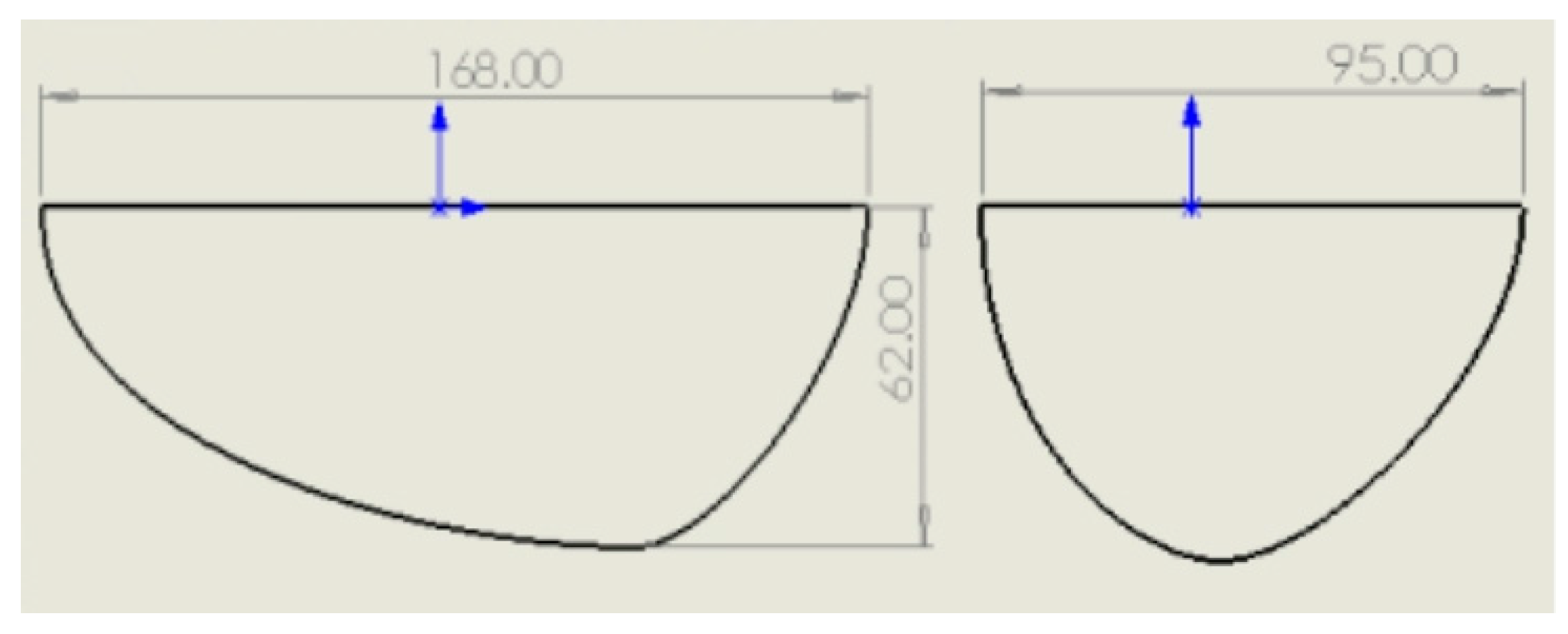
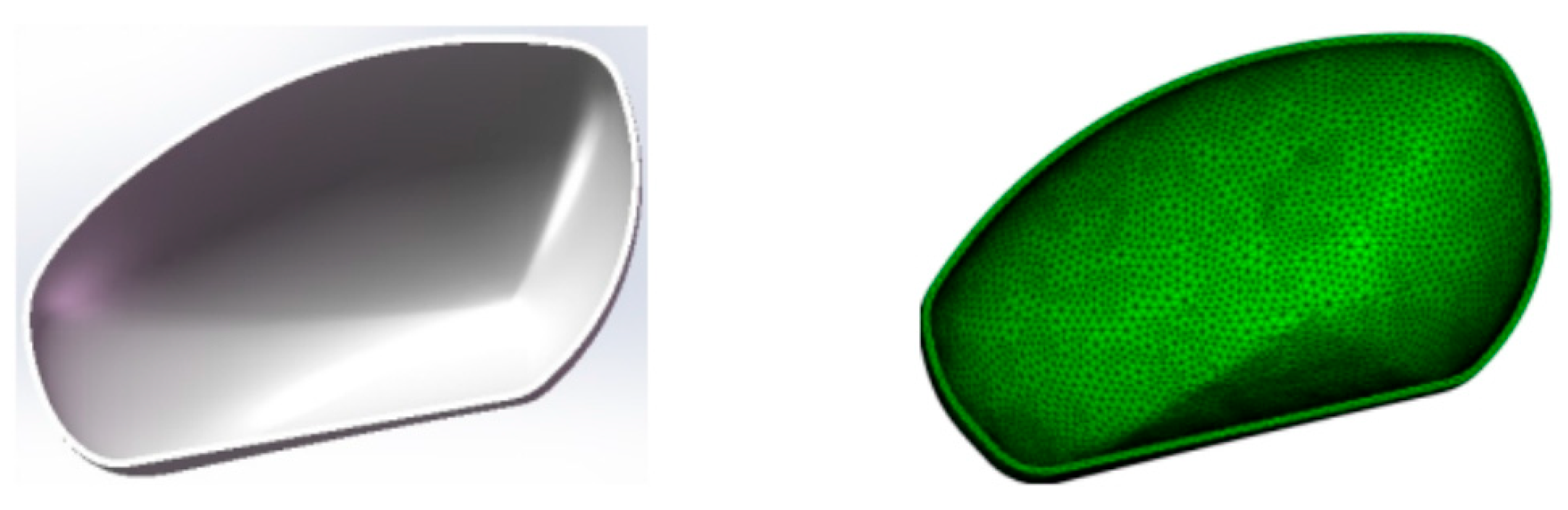
2.1. Establishment and Analysis of Plastic Part Models

The product was a rearview mirror shell with the dimensions and shape displayed in Figure 4 using the Solidworks software to construct a plastic model. The dimensions of the part were 168 mm (L) × 95 mm (W) × 62 mm (H), with an average wall thickness of 2 mm. The rearview mirror shell was a vehicle exterior component that required a smooth surface, minimal warping deformation, and high requirements for the injection molding process and cooling system.
The model of the rearview mirror shell was imported into the Moldflow software to generate a double-layer mesh. The total number of grid elements in the plastic parts was 60,564, and the total number of grid elements in the molds was 2,630,383. Figure 5 displays the models of the plastic portion and the mesh-generated plastic part. Model simulation and grid analysis of plastic parts were performed with the Moldflow software. Table 1 displays the material’s characteristics, a blend of polycarbonate (PC) and acrylonitrile butadiene styrene copolymer (ABS). The material’s thermal conductivity and specific heat properties are shown in Figure 6a,b, respectively. The coolant medium used was pure water. The coolant and ambient temperatures were set at 25 °C. The process settings used for simulation experiments are listed in Table 2. The material manufacturer is Kingfa Sci & Tech Co., Ltd. (Guangzhou, China), and the material brand is JH960-6900.

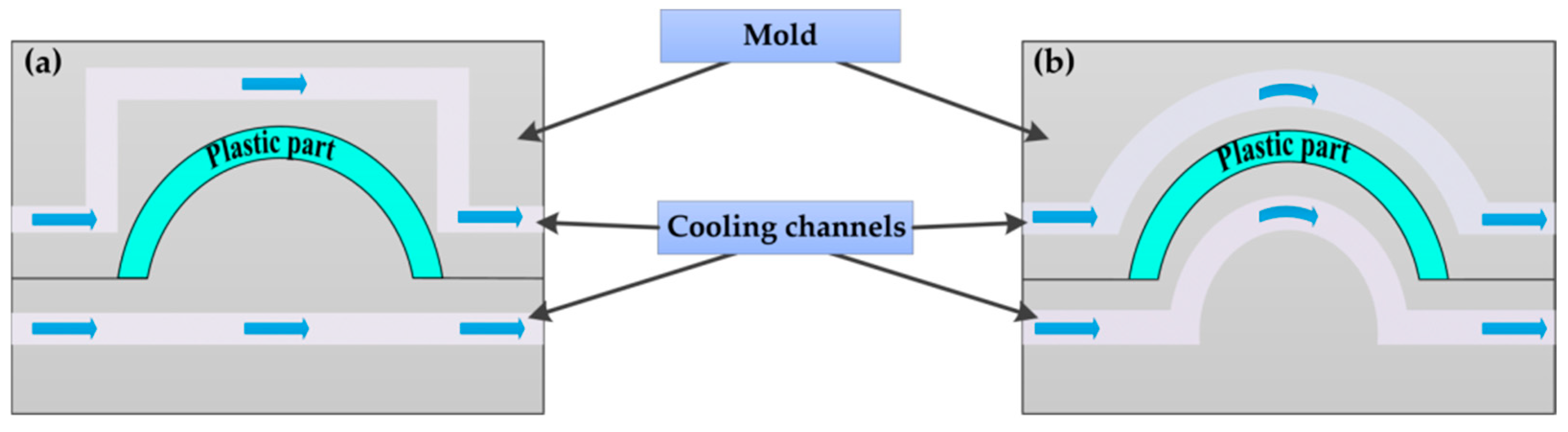
2.2. Design Scheme of Cooling Channels

If the cooling temperature of the formed channels is consistent during the injection cooling molding process, warping is less likely to occur in deformation. On the contrary, if the temperature distribution of the mold is highly uneven, plastic components will be prone to warping and deformation due to the thermal stress caused by temperature differences. Therefore, the design of channel systems is particularly crucial.

2.2.1. Cooling Scheme for the Cavity

As shown in Figure 7a, scheme A was an elliptical-shaped cavity cooling channel, which adopts an elliptical ring shape. The distance between the cooling channel and the surface of the plastic part was 15 mm. As shown in Figure 7b, scheme B was a spiral-shaped cooling channel, which spiraled around the outer surface of the plastic part and was 15 mm away from the surface of the plastic part. The distance between channels was 15 mm.

2.2.2. Cooling Scheme for the Core

As shown in Figure 7c, scheme C was a spiral-shaped cooling channel that spiraled around the inner surface of the plastic part and was 15 mm away from the surface of the plastic part. The distance between channels was 15 mm. As shown in Figure 7d, scheme D was an elliptical-shaped core cooling channel, which adopted an elliptical ring shape. The distance between the cooling channel and the surface of the plastic part was 15 mm.
The conformal cooling channel used a lot of curved tubes to match the surface of plastic objects better. Consequently, the cross-section of the conformal cooling channel was chosen to be circular. The advantage is that it can reduce flow loss and is not easy to accumulate in the channel during medium flow. Once the coolant accumulates in the channel, on the one hand, it will reduce the flow rate of the coolant, and on the other hand, it is easy to cause heat not to be quickly carried away, resulting in the poor cooling effect of the plastic parts. The diameter of the cooling channel for both the cavity and core was selected as 10 mm. Table 3 shows five different cooling circuit schemes, including conventional cooling channels (Figure 8) and conformal cooling channels.

3. Results

3.1. Hotspot Analysis

When considering the entire production cycle of injection molds, it is important to note that most of the heat introduced by the high-temperature melt is initially transferred to the mold in direct contact with it. This heat is then conveyed to the coolant, the external environment, or the worktable of the injection-molded component through various transfer methods, effectively facilitating the cooling of the product. The duration of the cooling process is primarily determined by the thermal properties of the plastic, the thickness of the components, and the specific process conditions in place.
Following the application of conventional cooling channels, the plastic product’s hot spots and critical positions were determined by the Moldflow simulation analysis method, as shown in Figure 9. A hotspot region, represented by the red area, results in uneven temperature distribution in plastic items, which produces uneven shrinkage and residual stress-induced warping deformation. Therefore, this location node (T40856) was discovered during the Moldflow mesh partitioning based on these problematic areas, as shown in Figure 10.
The simulated temperature curve of the location node (T40856) that corresponds to the hotspot area seen in Figure 10 over time is displayed in Figure 11. The process settings used for the simulation experiments are outlined in Table 2. Based on the graph, it is evident that the conventional cooling channel system (C1) shows significantly higher temperatures at specific locations during the cooling period as time progresses. In contrast, the conformal cooling system in C2 demonstrates lower temperatures at the relevant node compared to other cooling system configurations. Specifically, at 30 s of cooling, there is a temperature variance of 2.09 °C between C2 and C4. This disparity is attributed to the conformal cooling system in C4 achieving a more consistently uniform cooling temperature throughout the cooling process. The temperature curve depicted in Figure 12 illustrates the comprehensive cooling process for the entire plastic product within a single cycle at the position node. The curve exhibits an upward trend during the filling and injection stages, followed by a decline during the pressure-holding and cooling stages. It is evident from the graph that C2 and C4, situated at the position node, exhibit lower temperatures than C1. C2 and C4 demonstrate a temperature variance of 1.13 °C at a 30 s cooling period. Consequently, the temperature of the follower cooling channel system in C4 mode can be uniformly distributed, which can improve the warpage caused by thermal displacement.

3.2. Comparison of Different Cooling Channel System Designs

C1, C3, and C5 all have relatively lengthy cooling times, as shown in Figure 13a,c,e. The primary cause of this is that heat builds up inside the plastic component, and the cooling channel does not cover it, making it unable to dissipate heat swiftly. The cooling times for C2 and C4 differ by only a small amount, around 7.9 s, as seen in Figure 13b,d. The combination that takes the least time is C4, which is 4.371 s faster than C1, which takes the longest. Compared with C1, the cooling efficiency of C4 has increased by 35.48%, mainly due to the different distances between each component inside the plastic product core, the cooling circuit, and the deeper plastic product core. Additionally, due to the limitation of the drilling technique, the conventional cooling channel in C1 cannot accommodate the plastic part and effectively cool it, resulting in a more extended heat dissipation period. Compared to C2, C4 has reduced the cooling time by 0.024 s. This improvement is because in C4, schemes B and C cover almost all areas of the plastic and are closely attached to the surface of the plastic part, unlike in C2. The cooling path has a higher heat exchange efficiency than the plastic part, resulting in a further improved cooling effect.
The amount of warping deformation is smaller in C2 and C4 but more significant in C3 and C5, indicating that using a spiral cooling channel at one end of the cavity and core and an elliptical, circular cooling channel at the other end will result in significant warping deformation due to uneven cooling. It suggests that the heat exchange between the spiral cooling channel and the plastic part is much stronger than that of the elliptical cooling channel. It is worth noting that changing only the cooling channel of the core can significantly reduce the total warping deformation while changing the cavity channel has almost no significant effect on the total warping deformation. From a commercial value perspective, applying conformal cooling channels on the core of injection molds seems more suitable for most manufacturing applications.
As shown in Figure 13, the analysis was conducted using the temperature difference between the cavities. The lowest temperature difference between the cavities of the five combinations is 5.61 °C. Some combinations had higher temperatures, indicating that after the cooling time, some parts of the mold had already cooled down, and some heat still accumulated at the top of the deep cavity, resulting in higher temperatures. The maximum temperature difference between the cavities of C2 and C4 is not significant. The maximum temperature of the cavities of C4 is 32.43 °C. The temperature difference between C3 and C5’s cavities is not significant. C4 has the lowest temperature among the five combinations, which is 78.15% lower than the temperature difference between the cavities in C1, indicating that C4 has a uniform temperature distribution and can significantly reduce warping deformation caused by uneven cooling.

3.3. Orthogonal Experimental Design Analysis of Process Parameters

The injection molding process parameters were identified using the Moldflow software analysis to investigate the impact of process factors on warping. The preliminary analysis of the original injection molding process parameters showed that the total warping deformation of the plastic part was 0.6068 mm, with a large amount of warping deformation. As an external component, plastic parts have high requirements for warping deformation, and a further reduction in warping deformation is needed to meet the molding requirements. Therefore, it is necessary to optimize the combination of process parameters further to find the optimal injection molding process parameters to improve the product qualification rate of plastic parts.
In general, the uneven contraction of the plastic part will lead to uneven internal stress inside the plastic part. If the internal stress exceeds the strength limit of the material, it will cause the plastic part to produce warpage deformation. The excessive warpage deformation will lead to product demolding difficulties, excessive dimensional deviation, low molding quality, and other defects. It is challenging to meet the molding requirements regarding quality and shape. The plastic part design considers wall thickness, material, cooling systems, and injection molding parameters to minimize warping during the process. The product wall thickness, material, cooling system, and other aspects have been determined without change. This study used an orthogonal test for the optimization of injection molding process parameters, and analyzed the mold temperature, injection time, holding time, and holding pressure of five factors on the total warpage deformation of plastic parts, and the total warpage deformation as a quality indicator, through a range analysis to calculate the optimal combination, and design four levels of a five factor orthogonal table. The design of the 4-level 5-factor orthogonal table is listed in Table 4.
The results of the orthogonal experiment and the total amount of warping deformation are listed in Table 5. Under the total amount of warping deformation, the order of the range of the five factors of melt temperature, mold temperature, holding time, and holding pressure from small to large is R (holding time), R (mold temperature), R (injection time), R (melt temperature), and R (holding pressure). Among them, the range of injection time at each level is small, and the range of melt temperature and holding pressure is more extensive than the other three factors. The range of holding pressure at each level is the largest among the five factors, indicating that holding pressure has the most significant impact on the total amount of warping deformation of the plastic parts among the five factors. The total amount of warping deformation is shown in Figure 14a, and the injection molding condition A1B4C4D4E4 has the lowest total amount of warping deformation, where A1 is the mold temperature (60 °C), B4 is the melt temperature (240 °C), C4 is the injection time (3.0 s), D4 is the holding pressure (100 MPa), and E4 is the holding time (18 s). The total warpage deformation of the molded part is 0.3101 mm, which is 48.9 % less than the total warpage deformation of the optimized process parameters compared with the total warpage deformation of the original process parameters. As shown in Figure 14b, the optimized cooling temperature time is shortened, and the molding quality is improved significantly, which proves that the products produced by the optimized injection molding process parameters are better in terms of warpage deformation and molding quality after the optimization of process parameters by orthogonal test. Figure 14c,d show the cavity temperatures of the original and optimized groups.

3.4. Analysis of Experimental Design for Coolant Temperature

In the injection molding process, the plastic melt fills the mold cavity after the injection stage and begins to maintain pressure and cooling. During this period, the melt is subjected to pressure to compact further while the coolant undergoes heat exchange until the plastic component reaches its maximum temperature. Due to the uneven cooling and shrinkage of each component, the warping and deformation of the plastic parts are mainly caused by the heat accumulation at the top. The cooling channel cannot quickly dissipate the accumulated heat, resulting in a significant temperature difference between the top and bottom of the plastic part after reaching the top-out temperature. This study suggests that without changing the distribution of cooling channels, using different coolant temperatures in the cavity and core cooling channels may improve the uneven heat dissipation at the top and bottom of the plastic part, thereby improving the warping deformation without changing the coolant distribution. Temperature distribution is usually uncertain, and improper temperature settings may lead to inaccurate models. Therefore, the experiment aims to analyze the effect of different coolant temperatures in the cavity and core cooling channels on the warpage deformation of plastic parts. Table 6 shows eight types of cavity and core combinations with different coolant temperatures to analyze whether there are differences in the warping deformation of plastic parts under different coolant temperatures of the core and cavity.
Different coolant temperatures for the group core and cavity were simulated and analyzed using the Moldflow software. Figure 15 shows the numerical simulation results of the cavity and core with different coolant temperatures. When the cavity coolant temperature is 25 °C, and the core coolant temperature is 23 °C, 24 °C, 25 °C, and 26 °C, the total warpage deformation of the plastic part decreases with the increase in the core coolant temperature, which may be because the spiral cooling channel can cover most of the plastic part and has an excellent cooling effect. To ensure uniform cooling temperature between the cavity and core, the spiral cooling channel adopts a higher coolant temperature to maintain consistent cooling, indicating that the spiral cooling channel has a better cooling effect on plastic parts. When the core coolant temperature is 25 °C, and the cavity coolant temperatures are 23 °C, 24 °C, 25 °C, and 26 °C, respectively, the total amount of the warping and deformation of the plastic parts with the increase in the temperature of the cavity coolant rise.

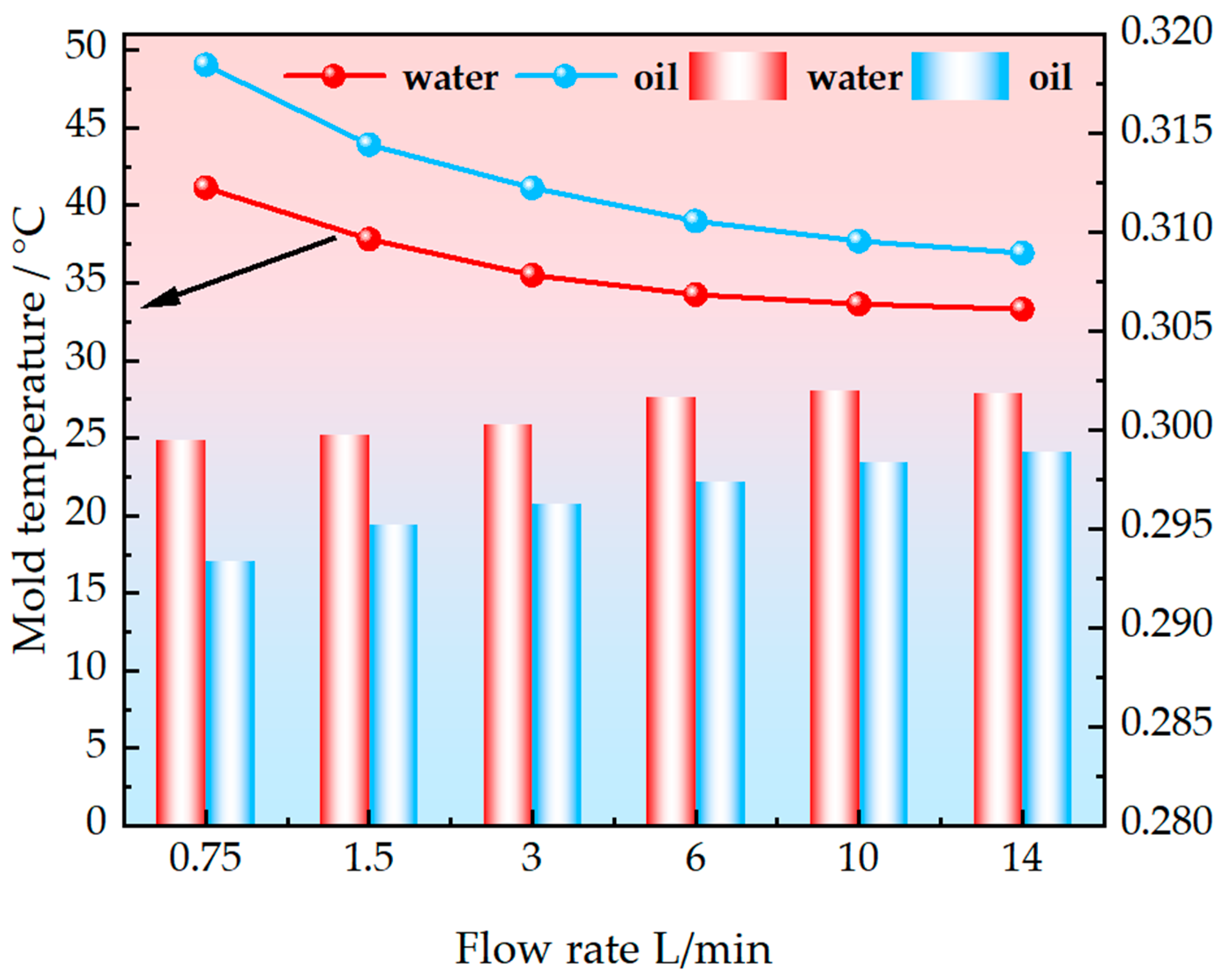
3.5. Analysis of the Influence of Different Cooling Medium and Flow Rates on Mold Temperature

Table 7 shows the different cooling media and flow rates required for injection mold simulation. This test simulated changing the plastic part’s mold temperature in a single-parameter experiment designed for the cooling phase of the injection molding cycle. We mainly explored the cooling fluid type and flow rate changes in the mold cavity wall temperature and warpage for different parameter settings each time by only changing a process parameter to observe the parameter’s effects on the mold wall temperature and warpage impact of the difference. The thermal and physical properties of the cooling medium are listed in Table 8.
Figure 16 shows the thermal response temperature and the amount of warpage change in different cooling media for mold temperature change at different flow rates. From the mold temperature distribution in the figure, it can be found that the cooling effect of cooling water is significantly better than that of cooling oil at the same flow rate, but the amount of warpage of the plastic parts using cooling oil is slightly better than that of cooling water. The cooling oil has a better effect than the cooling water in the low flow rate interval. When the flow rate is increased from 0.75 L/min to 6 L/min, the cooling oil has a significantly better effect on the mold temperature change than the cooling water, which may be due to the more uniform cooling effect of the cooling oil at this stage. When the cooling oil flow rate is low, the flow velocity of the oil slows down relative to the cooling water, which prolongs the residence time of the oil in the cooler, thereby more fully absorbing heat and achieving a more uniform cooling effect. In addition, low flow can also reduce the resistance of the oil circuit, lower the fluctuation in oil temperature, and further ensure the uniformity of the cooling effect. Mold temperature was less sensitive to the cooling medium flow rate if the cooling oil flow rate was increased to over 6 L/min. Instead, the mold temperature tends to stabilize. When the cooling medium is cooling water, it can be seen that the amount of warpage increases as the flow rate increases. When the cooling medium is cooling oil, it can be seen that the amount of warpage increases with the increase in flow rate. Therefore, the above conclusions can be used as a reference for producing process parameters to select and improve the quality of plastic parts.

4. Conclusions

Warping, shrinkage marks, and uneven shrinkage are common problems in injection molding. By using injection molds with conformal cooling channels (CCCs), the uniformity of mold temperature and the reduction in warping deformation can be improved, significantly improving the accuracy of products. This paper investigates the design optimization of the shape following the cooling system during the injection molding process for cooling time, cooling uniformity, and warpage rate. Based on the results obtained from this study, the following conclusions can be drawn:
  • This study conducts numerical simulation studies using several different configurations of cavities and cores with conformal cooling channels. The findings can provide a reference for designing cooling components and practical mold production applications in mold manufacturing enterprises.
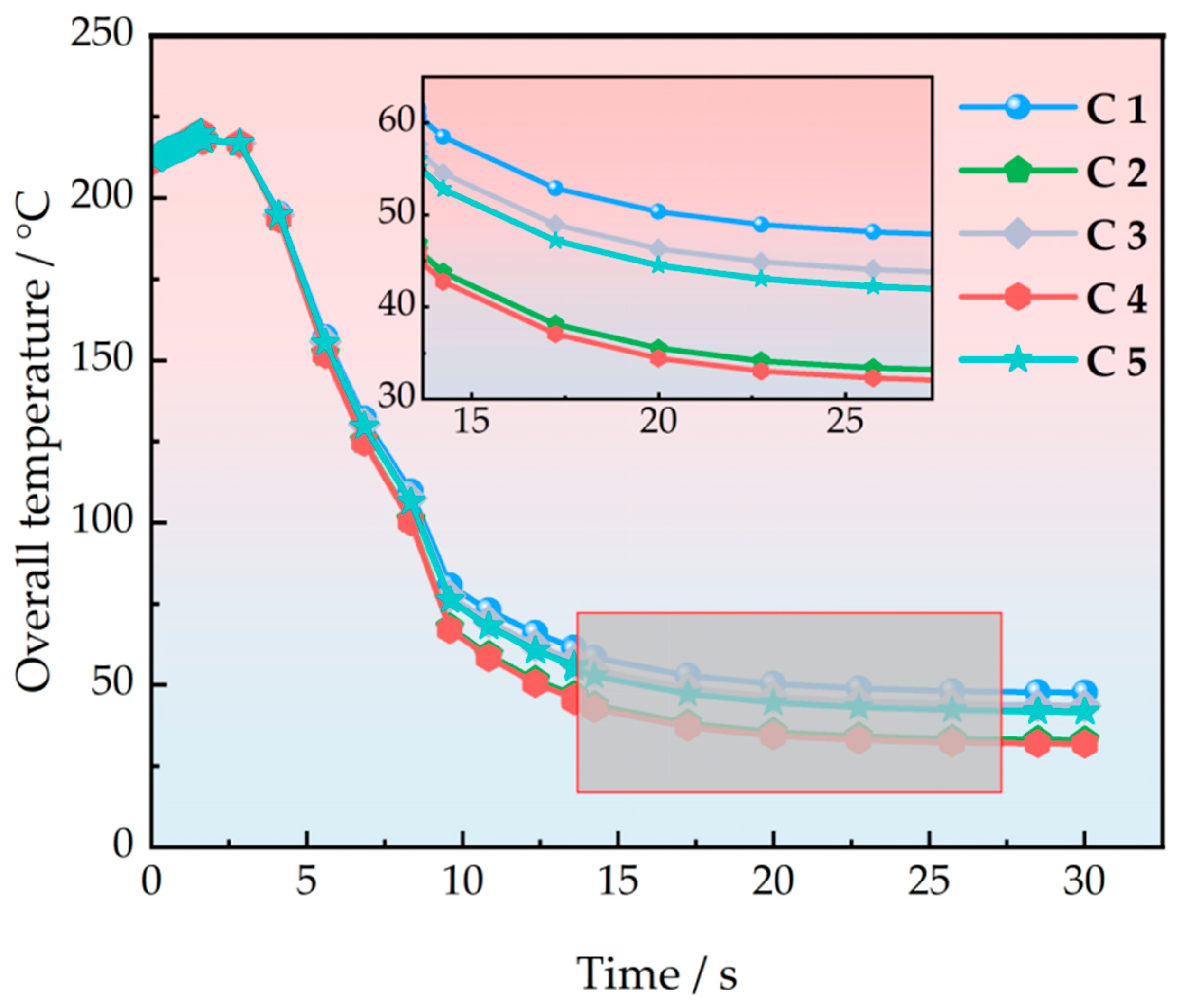
  • The cooling time difference between C2 and C4 is relatively small, around 7.9 s. Among them, C4 takes the shortest time, C1 takes the longest, and C4 is 4.371 s shorter than C1. Compared to C1, C4 has improved cooling efficiency by 35.48 %.
  • It is worth noting that when the cooling water channel of the injection mold core changes with the shape, the total warping deformation can be significantly reduced, while only changing the cavity water channel has almost no significant effect on the total warping deformation.
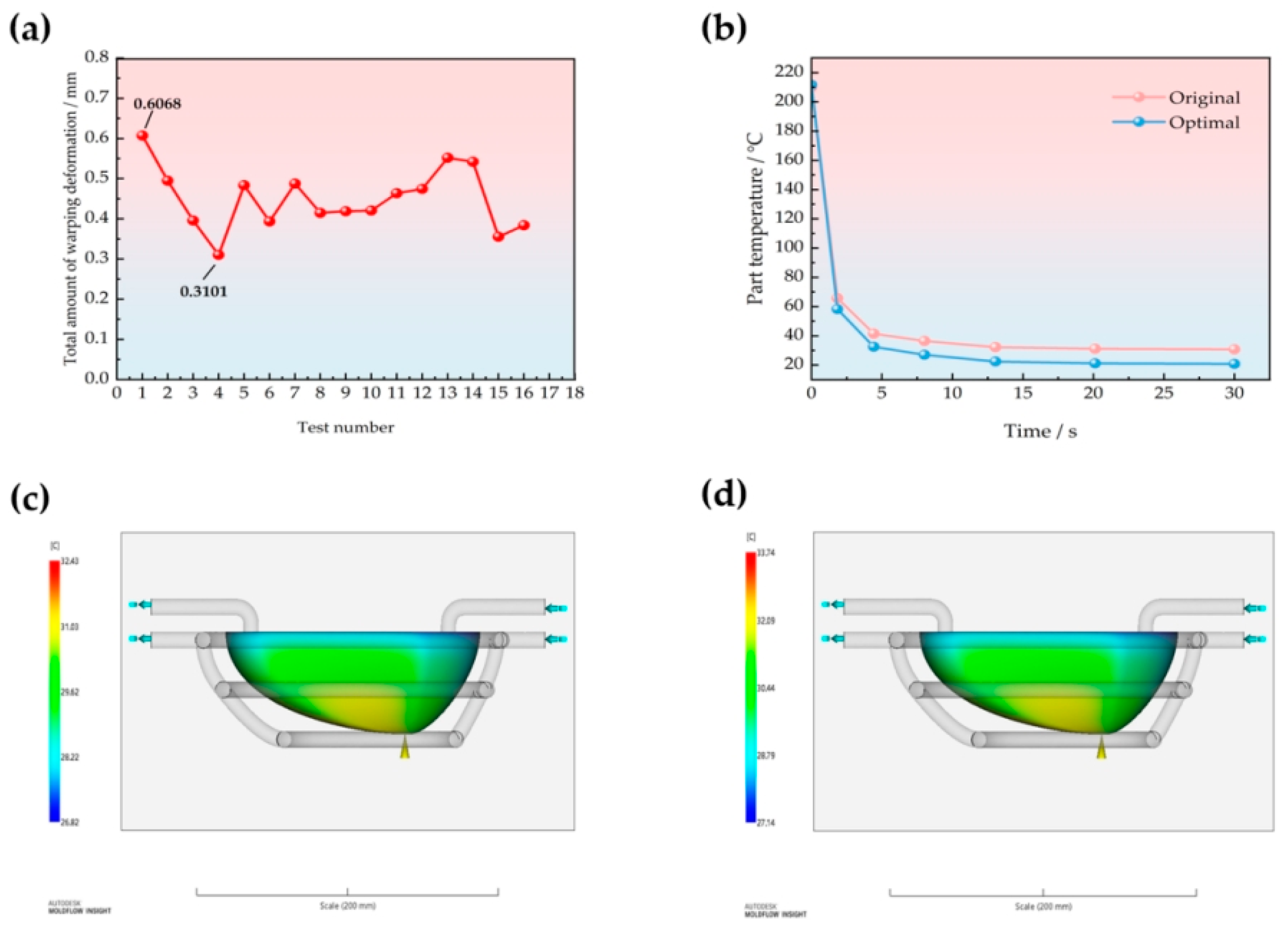
  • The total amount of warping deformation is the lowest when the injection molding process parameters are A1B4C4D4E4 where A1 is the mold temperature (60 °C), B4 is the melt temperature (240 °C), C4 is the injection time (3.0 s), D4 is the holding pressure (100 MPa), and E4 is the holding time (18 s).
  • When the temperature of the cavity coolant is 25 °C, and the temperature of the core coolant is 23 °C, 24 °C, 25 °C, and 26 °C, respectively, the total amount of warping deformation of the plastic part decreases with the increase in the core coolant temperature. When the temperature of the core coolant is 25 °C, and the temperature of the cavity coolant is 23 °C, 24 °C, 25 °C, and 26 °C, the total amount of warping deformation of the plastic part increases with the increase in the cavity coolant temperature.
  • Under other constant process conditions, there are significant differences in the influence of different cooling media and fluid flow rates on mold temperature, with cooling water having a significantly better effect than cooling oil. Increasing the cooling fluid flow rate can bring about a faster mold temperature drop when the fluid flow rate is low. When the flow rate exceeds a specific value, the cooling effect of the mold cavity wall temperature is not significant with the increase in fluid flow rate.

Author Contributions

Conceptualization, M.Z. and Z.T.; methodology, M.Z. and Z.T.; software, M.Z. and Z.T.; validation, M.Z. and Z.T.; formal analysis, M.Z. and Z.T.; investigation, M.Z. and Z.T.; resources, M.Z. and Z.T.; data curation, M.Z. and Z.T.; writing—original draft preparation, Z.T.; writing—review M.Z. and Z.T.; visualization, M.Z. and Z.T.; supervision, Z.T.; project administration, M.Z.; funding acquisition, M.Z. and Z.T. All authors have read and agreed to the published version of the manuscript.

Funding

This research was funded by the 2023 Anhui Province Youth Teacher Training Action Project, grant number JNFX2023134, and the Key Natural Science Research Project of Anhui Province, grant number 2024AH051862.

Data Availability Statement

The datasets used and/or analyzed during the current study are available from the corresponding author upon reasonable request.

Acknowledgments

Authors acknowledge the support of the Anhui Provincial Ministry of Education, Tongling Polytechnic, and Jiangsu University.

Conflicts of Interest

The authors declare no conflicts of interest.

References

  1. Wang, Y.; Lee, C. Design and Optimization of Conformal Cooling Channels for Increasing Cooling Efficiency in Injection Molding. Appl. Sci. 2023, 13, 7437. [Google Scholar] [CrossRef]
  2. Silva, H.M.; Noversa, J.T.; Fernandes, L.; Rodrigues, H.L. Design, simulation and optimization of conformal cooling channels in injection molds: A review. Int. J. Adv. Manuf. Technol. 2022, 120, 4291–4305. [Google Scholar] [CrossRef]
  3. Shinde, M.S.; Ashtanker, K.M. Additive manufacturing-assisted conformal cooling channels in mold manufacturing processes. Adv. Mech. Eng. 2017, 9, 1–14. [Google Scholar] [CrossRef]
  4. Wang, J.; Xuan, J.; Ni, Y.Y. Automatic design of conformal cooling channels of injection mold based on lotus root model. Int. J. Adv. Manuf. Technol. 2023, 125, 1879–1892. [Google Scholar] [CrossRef]
  5. Park, H.S.; Dang, X.P. Optimization of conformal cooling channels with array of baffles for plastic injection mold. Int. J. Precis. Eng. Manuf. 2010, 11, 879–890. [Google Scholar] [CrossRef]
  6. Gotlih, J.; Karner, T.; Belšak, R.; Ficko, M.; Berus, L.; Brajlih, T.; Pal, S. Design and manufacturing of conformal cooling channels for injection molding: A review. Int. J. Adv. Manuf. Technol. 2023, 687, 156–169. [Google Scholar] [CrossRef]
  7. Shinde, M.S.; Ashtanker, K.M.; Kuthe, A.M.; Dahake, S.W.; Mawale, M.B. Direct rapid manufacturing of molds with conformal cooling channels. Rapid Prototyp. J. 2018, 24, 1347–1364. [Google Scholar] [CrossRef]
  8. Wei, Z.; Wu, J.; Shi, N.; Li, L. Review of conformal cooling system design and additive manufacturing for injection molds. Math. Biosci. Eng. 2020, 17, 5414–5431. [Google Scholar] [CrossRef]
  9. Arman, S.; Lazoglu, I. A comprehensive review of injection mold cooling by using conformal cooling channels and thermally enhanced molds. Int. J. Adv. Manuf. Technol. 2023, 127, 2035–2106. [Google Scholar] [CrossRef]
  10. Zheng, Z.; Zhang, H.O.; Wang, G.L.; Qian, Y.P. Finite Element Analysis on the Injection Molding and Productivity of Conformal Cooling Channel. J. Shanghai Jiaotong Univ. 2021, 16, 231–235. [Google Scholar] [CrossRef]
  11. Kuo, C.C.; Qiu, S.X.; Lee, G.Y.; Zhou, J.; He, H.-Q. Characterizations of polymer injection molding tools with conformal cooling channels fabricated by direct and indirect rapid tooling technologies. Int. J. Adv. Manuf. Technol. 2021, 117, 343–360. [Google Scholar] [CrossRef]
  12. Chung, C.Y. Integrated Optimum Layout of Conformal Cooling Channels and Optimal Injection Molding Process Parameters for Optical Lenses. Appl. Sci. 2019, 9, 4341. [Google Scholar] [CrossRef]
  13. Feng, S.C.; Kamat, A.M.; Pei, Y.T. Design and fabrication of conformal cooling channels in molds: Review and progress updates. Int. J. Heat Mass Transf. 2021, 171, 121082. [Google Scholar] [CrossRef]
  14. Brooks, H.; Brigden, K. Design of conformal cooling layers with self-supporting lattices for additively manufactured tooling. Addit. Manuf. 2016, 11, 16–22. [Google Scholar] [CrossRef]
  15. Rocha, S.B.; Zhilsova, T.; Neto, V.; Oliveira, M.S.A. Optimization to assist design and analysis of temperature control strategies for injection molding-a review. Materials 2022, 15, 4048. [Google Scholar] [CrossRef] [PubMed]
  16. Torres-Albe, A.; Mercado-Colmenero, J.M.; Diaz-Perete, D.; Martin-Doñate, C. A new conformal cooling design procedure for injection molding based on temperature clusters and multidimensional discrete models. Polymers 2020, 12, 154. [Google Scholar] [CrossRef]
  17. Saifullah, A.B.M.; Masood, S.H.; Sbarski, I. Thermal-structural analysis of bi-metallic conformal cooling for injection moulds. Int. J. Adv. Manuf. Technol. 2012, 62, 123–133. [Google Scholar] [CrossRef]
  18. Rahim, S.Z.A.; Sharif, S.; Zain, A.M.; Nasir, S.M.; Saad, R.M. Improving the quality and productivity of molded parts with a new design of conformal cooling channels for the injection molding process. Adv. Polym. Technol. 2016, 35, 1–10. [Google Scholar] [CrossRef]
  19. Vojnová, E. The benefits of a conforming cooling systems the molds in injection moulding process. Procedia Eng. 2016, 149, 535–543. [Google Scholar] [CrossRef]
  20. Kuo, C.C.; Xu, Y.X. A simple method of improving warpage and cooling time of injection molded parts simultaneously. Int. J. Adv. Manuf. Technol. 2022, 122, 619–637. [Google Scholar] [CrossRef]
  21. Kuo, C.-C.; Chen, W.-H. Improving Cooling Performance of Injection Molding Tool with Conformal Cooling Channel by Adding Hybrid Fillers. Polymers 2021, 13, 1224. [Google Scholar] [CrossRef] [PubMed]
  22. Mercado-Colmenero, J.M.; Torres-Alba, A.; Catalan-Requena, J.; Martin-Doñate, C. A new conformal cooling system for plastic collimators based on the use of complex geometries and optimization of temperature profiles. Polymers 2021, 13, 2744. [Google Scholar] [CrossRef] [PubMed]
  23. Kitayama, S.; Miyakawa, H.; Takano, M.; Aiba, S. Multi-objective optimization of injection molding process parameters for short cycle time and warpage reduction using conformal cooling channel. Int. J. Adv. Manuf. Technol. 2017, 88, 1735–1744. [Google Scholar] [CrossRef]
  24. Wang, X.Y.; Li, Z.; Gu, J.F.; Ruan, S.; Shen, C.; Wang, X. Reducing service stress of the injection-molded polycarbonate window by optimizing mold construction and product structure. Int. J. Adv. Manuf. Technol. 2016, 86, 1691–1704. [Google Scholar] [CrossRef]
  25. Kitayama, S. Process parameters optimization in plastic injection molding using metamodel-based optimization: A comprehensive review. Int. J. Adv. Manuf. Technol. 2022, 121, 7117–7145. [Google Scholar] [CrossRef]
  26. Yasin, S.B.M.; Mohd, N.F.; Mahmud, J.; Whashilah, N.S.; Razak, Z. A reduction of protector cover warpage via topology optimization. Int. J. Adv. Manuf. Technol. 2018, 98, 2531–2537. [Google Scholar] [CrossRef]
  27. Au, K.M.; Yu, K.M. Modeling of multi-connected porous passageway for mould cooling. Comput.-Aided Des. 2011, 43, 989–1000. [Google Scholar] [CrossRef]
  28. Wang, Y.; Yu, K.M.; Wang, C.C.L.; Zhang, Y. Automatic design of conformal cooling circuits for rapid tooling. Comput.-Aided Des. 2011, 43, 1001–1010. [Google Scholar] [CrossRef]
  29. Kuo, C.C.; Qiu, S.X.; Yang, X.Y. A low-cost and highly efficient method of reducing coolant leakage for direct metal printed injection mold with cooling channels using optimum heat treatment process procedures. Int. J. Adv. Manuf. Technol. 2021, 115, 2553–2570. [Google Scholar] [CrossRef]
  30. Eiamsa-Ard, K.; Wannissorn, K. Conformal bubbler cooling for molds by metal deposition process. Comput.-Aided Des. 2015, 69, 126–133. [Google Scholar] [CrossRef]
  31. Dang, X.P.; Park, H.S. Design of U-shape milled groove conformal cooling channels for plastic injection mold. Int. J. Precis. Eng. Manuf. 2011, 12, 73–84. [Google Scholar] [CrossRef]
  32. Nagahanumaiah; Ravi, B. Effects of injection molding parameters on shrinkage and weight of plastic part produced by DMLS mold. Rapid Prototyp. J. 2009, 15, 179–186. [Google Scholar] [CrossRef]
  33. Venkatesh, G.; Kumar, Y.R. Thermal Analysis for Conformal Cooling Channel. Mater. Today Proc. 2017, 4, 2592–2598. [Google Scholar] [CrossRef]
  34. Abbes, B.; Abbes, F.; Abdessalam, H.; Upganlawar, A. Finite element cooling simulations of conformal cooling hybrid injection molding tools manufactured by selective laser melting. Int. J. Adv. Manuf. Technol. 2019, 103, 2515–2522. [Google Scholar] [CrossRef]
  35. He, B.; Ying, L.; Li, X.D.; Hu, P. Optimal design of longitudinal conformal cooling channels in hot stamping tools. Appl. Therm. Eng. 2016, 106, 1176–1189. [Google Scholar] [CrossRef]
  36. Huang, W.T.; Tsai, C.L.; Ho, W.H.; Chou, J. Application of Intelligent Modeling Method to Optimize the Multiple Quality Characteristics of the Injection Molding Process of Automobile Lock Parts. Polymers 2021, 13, 2515. [Google Scholar] [CrossRef]
  37. Au, K.M.; Yu, K.M. A scaffolding architecture for conformal cooling design in rapid plastic injection moulding. Int. J. Adv. Manuf. Technol. 2007, 34, 516. [Google Scholar] [CrossRef]
  38. Luh, Y.P.; Wang, H.L.; Iao, H.W. Effect of the layout design of hive-shaped conformal cooling channels on the deflection of family molds. Int. J. Adv. Manuf. Technol. 2023, 128, 1179–1198. [Google Scholar] [CrossRef]
  39. Wang, Y.; Yu, K.M.; Wang, C.C.L. Spiral and conformal cooling in plastic injection molding. Comput.-Aided Des. 2015, 63, 1–11. [Google Scholar] [CrossRef]
  40. Kurtulud, K.; Bolatturk, A.; Coskun, A.; Gürel, B. An experimental investigation of the cooling and heating performance of a gravity die casting mold with conformal cooling channels. Appl. Therm. Eng. 2021, 194, 117105. [Google Scholar] [CrossRef]
  41. Yan, Z.; Qian, Y.; Huang, W.; Zhou, X.; Gong, X. Research on heat transfer enhancement of variable cross sectional conformal cooling of injection mold based on fluent. J. Mech. Eng. Res. 2018, 10, 7–20. [Google Scholar] [CrossRef]
  42. Jahan, S.A.; Wu, T.; Zhang, Y.; El-Mounayri, H.; Tovar, A.; Zhang, J.; Acheson, D.; Nalim, R.; Guo, X.; Lee, W.H. Implementation of Conformal Cooling & Topology Optimization in 3D Printed Stainless Steel Porous Structure Injection Molds. Procedia Manuf. 2016, 5, 901–915. [Google Scholar] [CrossRef]
  43. Choi, J.H.; Kim, J.S.; Han, E.S.; Park, H.P.; Rhee, B.O. Study on an optimized configuration of conformal cooling channel by branching law. In Proceedings of the ASME 2014 12th Biennial Conference on Engineering Systems Design and Analysis, Copenhagen, Denmark, 25–27 July 2014; Volume 1. [Google Scholar] [CrossRef]
  44. Kurtaran, H.; Erzurumlu, T. Efficient warpage optimization of thin shell plastic parts using response surface methodology and genetic algorithm. Int. J. Adv. Manuf. Technol. 2006, 27, 468–472. [Google Scholar] [CrossRef]
  45. Li, Z.; Wang, X.; Gu, J.; Ruan, S.; Shen, C.; Lyu, Y.; Zhao, Y. Topology optimization for the design of conformal cooling system in thin-wall injection molding based on BEM. Int. J. Adv. Manuf. Technol. 2018, 94, 1041–1059. [Google Scholar] [CrossRef]
  46. Kuo, C.C.; Jiang, Z.F.; Lee, J.H. Effects of cooling time of molded parts on rapid injection molds with different layouts and surface roughness of conformal cooling channels. Int. J. Adv. Manuf. Technol. 2019, 103, 2169–2182. [Google Scholar] [CrossRef]
  47. Xu, X.; Sachs, E.; Allen, S. The design of conformal cooling channels in injection molding tooling. Polym. Eng. Sci. 2001, 41, 1265–1279. [Google Scholar] [CrossRef]
  48. Dimla, D.E.; Camilotto, M.; Miani, F. Design and optimisation of conformal cooling channels in injection moulding tools. J. Mater. Process Technol. 2005, 164–165, 1294–1300. [Google Scholar] [CrossRef]
  49. Park, H.S.; Pham, N.H. Design of conformal cooling channels for an automotive part. Int. J. Automot. Technol. 2009, 10, 87–93. [Google Scholar] [CrossRef]
  50. Mercado-Colmenero, J.M.; Martin-Donate, C.; Rodriguez-Santiago, M.; Moral-Pulido, F.; Rubio-Paramio, M.A. A new conformal cooling lattice design procedure for injection molding applications based on expert algorithms. Int. J. Adv. Manuf. Technol. 2019, 102, 1719–1746. [Google Scholar] [CrossRef]
  51. Shayfull, Z.; Sharif, S.; Zain, A.M.; Ghazali, M.F.; Saad, R.M. Potential of conformal cooling channels in rapid heat cycle molding: A review. Adv. Polym. Technol. 2014, 33, 21381. [Google Scholar] [CrossRef]
  52. Kanbur, B.B.; Suping, S.; Duan, F. Design and optimization of conformal cooling channels for injection molding: A review. Int. J. Adv. Manuf. Technol. 2020, 106, 3253–3271. [Google Scholar] [CrossRef]
Figure 1. Injection molding process.
Processes 13 00234 g001
Figure 2. Categories of injection molding cooling channels. (a) Conventional cooling channel and (b) conformal cooling channel.
Processes 13 00234 g002
Figure 3. Flowchart of the experimental methodology.
Processes 13 00234 g003
Figure 4. Injection part structure diagram.
Processes 13 00234 g004
Figure 5. Plastic part model and mesh generation model.
Processes 13 00234 g005
Figure 6. Material properties (a) Thermal conductivity and (b) specific heat.
Processes 13 00234 g006
Figure 7. Conformal cooling channel design for cavity and core. Cavity insert with (a) elliptical CCC and (b) spiral CCC; core insert with (c) spiral CCC and (d) elliptical CCC.
Processes 13 00234 g007
Figure 8. Cooling channel design of conventional cooling system.
Processes 13 00234 g008
Figure 9. Hotspot region of the temperature distribution.
Processes 13 00234 g009
Figure 10. Location node (T40856).
Processes 13 00234 g010
Figure 11. The part temperature of temperature distribution for the location node with different cooling channels.
Processes 13 00234 g011
Figure 12. Overall temperature of temperature distribution for the location node with different cooling channels.
Processes 13 00234 g012
Figure 13. Radar chart for different cooling channel system designs: (a) conventional cooling channel; (b) cavity insert with elliptical CCC and core insert with spiral CCC; (c) cavity insert with spiral CCC and core insert with elliptical CCC; (d) cavity insert with spiral CCC and core insert with spiral CCC; (e) cavity insert with elliptical CCC and core insert with elliptical CCC.
Processes 13 00234 g013
Figure 14. (a) The total amount of warping deformation; (b) the part temperature of temperature distribution for the original and optimized groups; (c) the cavity temperatures of the original group; (d) the cavity temperatures of the optimized group.
Processes 13 00234 g014
Figure 15. The numerical simulation results of the cavity and core with different coolant temperatures.
Processes 13 00234 g015
Figure 16. Thermal response temperature and warping variation in different cooling media under different flow rates.
Processes 13 00234 g016
Table 1. Material characteristics.
Mechanical PropertiesNumerical Value
Density (g/cm3)1.1859
Poisson’s ratio0.4
Modulus E (MPa)2780
Shear modulus (MPa)992.9
Table 2. Process parameters for the Moldflow simulation.
Process ParametersNumerical Value
Melt temperature (°C)210
Mold temperature (°C)60
Injection time (s)1.5
Holding time (s)12
Holding pressure (MPa)70
Coolant temperature (°C)25
Flow rate (lit/min)10
Table 3. Scheme combination of cooling channels.
No.Scheme Combination
Combination 1 (C1)Conventional cooling channel
Combination 2 (C2)Cavity insert with elliptical CCC and core insert with spiral CCC
Combination 3 (C3)Cavity insert with spiral CCC and core insert with elliptical CCC
Combination 4 (C4)Cavity insert with spiral CCC and core insert with spiral CCC
Combination 5 (C5)Cavity insert with elliptical CCC and core insert with elliptical CCC
Table 4. Control factors and levels.
Control FactorsLevel
1234
A. Mold temperature (°C)60657075
B. Melt Temperature (°C)210220230240
C. Injection time (s)1.52.02.53.0
D. Holding pressure (MPa)708090100
E. Holding time (s)12141618
Table 5. The results of the orthogonal experiment.
NoControl FactorsQuality Index
Mold Temperature (°C)Melt
Temperature
(°C)
Injection Time (s)Holding Pressure (MPa)Holding Time (s)Total Amount of Warping Deformation (mm)
1602101.570120.6068
2602202.080140.4948
3602302.590160.3958
4602403.0100180.3101
5652102.090180.4834
6652201.5100160.3935
7652303.070140.4875
8652402.580120.4145
9702102.5100140.4192
10702203.090120.4215
11702301.580180.4640
12702402.070160.4751
13752103.080160.5536
14752202.570180.5426
15752302.0100120.3555
16752401.590140.3838
K10.451880.515750.462030.528000.44958-
K20.444730.463100.452200.481730.44633-
K30.444950.425700.443030.421130.45450-
K40.458880.395880.443180.369580.45003-
R0.014150.119880.019000.158430.00818-
Table 6. Eight types of cavity and core combinations with different coolant temperatures.
No.Cavity Temperature (°C)Core Temperature (°C)
12325
224
325
426
52523
624
725
826
Table 7. The different cooling media and flow rates.
No.Cooling MediumVelocity (L/min)
1Cooling water0.75
2Cooling oil0.75
3Cooling water1.5
4Cooling oil1.5
5Cooling water3
6Cooling oil3
7Cooling water6
8Cooling oil6
9Cooling water10
10Cooling oil10
11Cooling water14
12Cooling oil14
Table 8. Thermophysical properties of cooling medium.
Thermophysical PropertiesCooling Medium
Cooling WaterCooling Oil
Density (g/cm3)0.9880.836
Specific heat (J/kg·C)41802250
Thermal conductivity (W/m·C)0.6430.136
Disclaimer/Publisher’s Note: The statements, opinions and data contained in all publications are solely those of the individual author(s) and contributor(s) and not of MDPI and/or the editor(s). MDPI and/or the editor(s) disclaim responsibility for any injury to people or property resulting from any ideas, methods, instructions or products referred to in the content.

