Article

Geothermal Heat Pump for Space Cooling and Heating in Kuwaiti Climate

College of Engineering and Technology, American University of the Middle East, Egaila 54200, Kuwait
*
Author to whom correspondence should be addressed.
Processes 2024, 12(5), 910; https://doi.org/10.3390/pr12050910
Submission received: 20 March 2024 / Revised: 20 April 2024 / Accepted: 27 April 2024 / Published: 29 April 2024
(This article belongs to the Section Energy Systems)

Abstract

:
Kuwait stands as one of the hottest locations globally, experiencing scorching temperatures that can soar to 50 °C during the summer months. Conversely, in the winter months of December and January, temperatures may plummet to less than 10 °C. Maintaining a comfortable temperature indoors necessitates a substantial amount of energy, particularly during the scorching summer seasons. In Kuwait, most of the electrical energy required for functions such as air conditioning and lighting is derived from fossil fuel resources, contributing to escalating air pollution and global warming. To reduce dependence on conventional energy sources for heating and cooling, this article presents a case study to explore the potential of using geothermal energy for space heating and cooling in Kuwait. The case study involves utilizing a geothermal heat pump (water-sourced heat pump) in conjunction with a vertical-borehole ground heat exchanger (VBGHE). The mentioned system is deployed to regulate the climate in a six-floor apartment block comprising a small two-bedroom apartment on each level, each with a total floor area of 57 m2. Two geothermal heat pumps, each with a cooling capacity of 2.58 kW and a heating capacity of 2.90 kW, connected to two vertical-borehole heat exchangers, were deployed for each apartment to maintain temperatures at 22 °C in winter and 26 °C in summer. The findings indicate that the estimated annual energy loads for cooling and heating for the apartment block are 42,758 kWh and 113 kWh, respectively. The corresponding electrical energy consumption amounted to 9294 kWh for space cooling and 113 kWh for space heating. The observed peak cooling load was approximately 9300 kJ/h (2.58 kW) per apartment, resulting in a power density of 45 W/m2. Moreover, the HP system achieved a 22% reduction in annual electric energy consumption compared to conventional air conditioning systems. This reduction in electric energy usage led to an annual CO2 reduction of 6.6 kg/m2.

1. Introduction

Kuwait, a country characterized by very high temperatures, faces unique challenges in managing its energy consumption per capita, which reached an all-time high of 17,738.924 kWh in 2006 [1]. With scorching summer temperatures reaching 50 °C and beyond and relatively milder winters, the demand for energy fluctuates significantly throughout the year [2]. The majority of energy consumption in Kuwait is attributed to the extensive use of electricity for air conditioning, given the imperative need to maintain comfortable indoor temperatures during the intense heat. Air conditioning in Kuwait is a major consumer of electricity, accounting for around 70% to 75% of the total annual electricity consumption [3,4]. This is due to the country’s hot and arid climate, with long summers and average temperatures exceeding 40 °C. Additionally, energy is used for common purposes, such as lighting, powering appliances, and a variety of other residential and industrial applications.
To regulate energy consumption, the Ministry of Electricity and Water (MEW) published a document entitled The Energy Conservation Code for Buildings [4], through which the minimum energy requirements for the design and construction of energy-efficient governmental and commercial buildings have been laid out. The code covers different aspects, including the insulation of building envelopes, lighting systems, fenestration, heating, ventilation, and air conditioning systems. The code provided the maximum allowable power density (W/m2) for A/C systems and lighting for government, commercial, and residential buildings. In addition, it also tabulated the maximum allowable U-values for different walls and roofs of all types of buildings. Furthermore, the Public Authority for Industry (PAI) [5] produced a standard that specifies the requirements of energy efficiency labeling as well as the minimum energy performance standard (MEPS) for direct expansion (DX) air conditioners with capacities up to and including 70,000 Btu/h. The standard provided the MEPS values in addition to the star rating based on the energy efficiency ratio (EER) in (BTU/h)/W and the power rating per refrigeration ton (kW/RT) for different types of air conditioners. Ben Essa [6] derived a method for calculating the cooling load in a residential building in Kuwait but stopped short of proposing an HVAC system to cool the space. To reduce energy consumption for space cooling in Kuwait, Darwish [3] proposed measures that can be implemented either at the building design-construction stage or the retrofitting of existing buildings to make buildings more energy efficient. Likewise, the study did not provide an alternative energy resource to meet the reduced cooling load.
The above-mentioned work focused on reducing the consumption of electric energy devoted to space cooling either by setting standards for buildings’ construction materials for the cooled spaces or mandating the use of efficient DX systems and other relevant appliances. Although this is a step in the right direction, a drastic improvement in addressing environmental concerns and achieving energy efficiency can only be expected through finding alternative energy resources to fossil fuels. Given that a substantial part of electricity usage in Kuwait is dedicated to space cooling, investigating alternative cooling methods with reduced dependence on conventionally sourced electricity could have a notable impact on the overall energy consumption in the country. Any reduction in the consumption of conventionally sourced electricity would yield positive environmental outcomes.
Engineers and researchers need to explore innovative methods to promote energy efficiency and foster a sustainable environment. This pursuit could involve enhancing the efficacy of electric power generation and consumption, as suggested in [7], or by embracing alternative energy sources for various applications, including space heating and cooling. Examples of such aternative energy resources implemented to achieve sustianable invironment include fuel cell technology [8], solar energy [9], wind energy, and geothermal energy [10,11]. Darwish [12] investigated the use of commercially available phosphoric acid fuel cells for space cooling in high-rise apartment buildings in Kuwait. Al-Homoud et al. [13] presented the performance results of a 10-ton cooling load system comprised of a 300 m2 flat solar collector and a small vapor absorption refrigeration installed on an office building at the Ministry of Defense in Kuwait. Narayanan et al. [14] conducted a numerical investigation using TRNSYS v18 software on different configurations of solar desiccant cooling systems for space cooling in Kuwait. They concluded that the studied configurations were able to maintain a comfortable thermal environment with air temperatures within the required range of 18 °C to 26 °C. While the existing efforts towards energy conservation in Kuwait are commendable, further research aimed at identifying alternative methods to reduce cooling energy consumption in the country remains essential.
This study introduces a different approach that predominantly relies on alternative energy sources. The research employs TRNSYS to model a geothermal heat pump (GHP), otherwise known as a ground-source heat pump (GSHP), in conjunction with a vertical-borehole ground heat exchanger (VBGHX) for heating and cooling purposes in a typical two-bedroom apartment block in Kuwait. GHPs are considered among the most efficient and quietest HVAC systems [11]. Ping Cui et al. [15] and Eswiasi et al. [16] have recently conducted an extensive review related to the types, the analysis, and the applications of the different types of GHPs. Meanwhile, many researchers have used TRNSYS to model alternative energy resources for space heating and cooling in different areas around the world. Examples of such work include the use of evacuated-tube solar collectors in combination with an absorption chiller to cool a standard single-story dwelling in Pakistan [17]. The 3.52 kW absorption chiller was powered by hot water sourced from a 12 m2 evacuated-tube solar collector and a 2 m3 thermal storage tank. The setup was designed to meet a 2 kW cooling demand, maintaining the indoor temperature at 26 °C.
Jadid et al. [18] utilized TRNSYS in combination with Engineering Equation Solver v11 (EES) software to examine the implementation of a 3.5 kW solar ejector cooling system (SECS) for cooling two office buildings located in semi-arid and hot-humid climates of Iran. The investigation aimed to assess the impact of employing R600a and R290 hydrocarbon refrigerants on system performance. Throughout the study period, the thermodynamic energy and exergy of the cooling systems, utilizing both refrigerants, underwent comprehensive evaluation via simulation at the specified study sites. Sun et al. [19] employed TRNSYS to model the integration of geothermal and solar energy for heating a typical building in an arid and cooled region of China. The implemented system included a single GSHP with a heating capacity of 355 kW and a 125 m deep VBGHE with soil thermal conductivity and capacity values of 2.33 W·m−1·K−1 and 2016 kJ·m−3·K−1, respectively, along with a 66 m2 vacuum-tube solar collector. Chargui et al. [20] investigated the use of geothermal heat pumps for greenhouse heating in Tunisia. Their study centered on examining how climatic conditions impact the operating conditions of the heat pump and, consequently, its performance. The findings indicated a direct correlation between the coefficient of performance (COP) of the heat pump and the rise in water inlet temperature. Additionally, the study demonstrated the potential for CO2 to be effectively utilized as a working fluid in heat pumps, offering competitive performance.

2. Description of the Building

The building considered in this study is a six-floor apartment block made of a single two-bedroom apartment on each floor with a total apartment area of 57 m2. The apartment is composed of two bedrooms, a bathroom, an open kitchen, and a living space, as shown in Figure 1. All six apartments are assumed to be identical.
Houses and apartments in Kuwait are typically built out of concrete roofs and brick walls. Unlike governmental and commercial buildings, to the authors’ knowledge, there are no energy conservation codes in place for residential buildings. However, according to a study conducted by Moncef Krarit for the United Nations Development Account Project [21], the average U-value of Kuwait’s current residential buildings is 0.693 (W/m2·K) for the roof and 0.511 (W/m2·K) for the walls. Similar or better than these reported U-values have been considered in this study. The U-values of construction materials directly influence cooling and heating loads, subsequently affecting electric energy consumption. Lower U-values indicate better heat resistance and reduced energy loss.
After constructing a single apartment in Sketchup, it was transferred to TRNBuild v3.0 software to incorporate details regarding the properties of the walls, windows, floor, and ceiling construction materials. TRNBuild facilitates the assignment of various significant parameters, including infiltration, ventilation, gains, and losses. As illustrated in Table 1, the living room’s surface type, construction type, areas, and category type were configured in TRNBuild as an example.
Table 2 shows the properties of the assigned walls, windows, ceiling, and floor. The floor and ceiling were assumed to have the same construction materials. It is worth noting that floor and ceiling material types were set as “BND_Ceiling”. “BND_Ceiling” in TRNSYS denotes a boundary condition that represents a building’s ceiling or a particular zone inside a building. Usually, this boundary condition would specify the ceiling’s thermal behavior and features, such as its insulating qualities, thermal conductivity, and interactions with the surroundings. Furthermore, the windows were assumed to be of a double-pane type with a U-value equal to 1.1 W/m2·K and a g-value (total solar energy transmittance) of 0.62.
In addition, in TRNSYS, TRNBuild allows for infiltration and heat gain to be assigned. The assumed infiltration values were 0.4, 0.3, and 0.6 air change per hour (ACH) for the living room, the bedrooms, and the bathroom, respectively. Usually, a minimum of one-third air change per hour (ACH) is recommended. ASHRAE Standard 62.2 [22] provides guidelines for ventilation air requirements in low-rise residences. According to this standard, forced ventilation is mandated for houses with infiltration rates below 0.35 ACH. In our study, we assumed 0.4 ACH for the bedrooms and the living room and 0.6 ACH for the bathroom due to the existence of the exhaust fan. The main source of heat gain is assumed to be through occupancy and lighting. The number of occupants was assumed to be one person in each of the bedrooms, two persons in the living room, and one person in the bathroom. All occupants were assumed to be resting at 24 °C and generating 95 W as per ASHRAE standards. The lighting heat gain values were assumed to be 10 W/m2 for the living room and 6 W/m2 for all other spaces. These values fall within the range specified in the literature [4,21]. Figure 2 shows the utilization schedule considered for lighting. The lighting schedule employed in this study reflects a typical working day. However, during weekends, holidays, or periods of curfew such as those experienced during the COVID-19 pandemic, the lighting schedule would likely differ. It is expected that there would be higher utilization of lighting load throughout most of the night and to some extent during the daytime.

3. Description of the Model

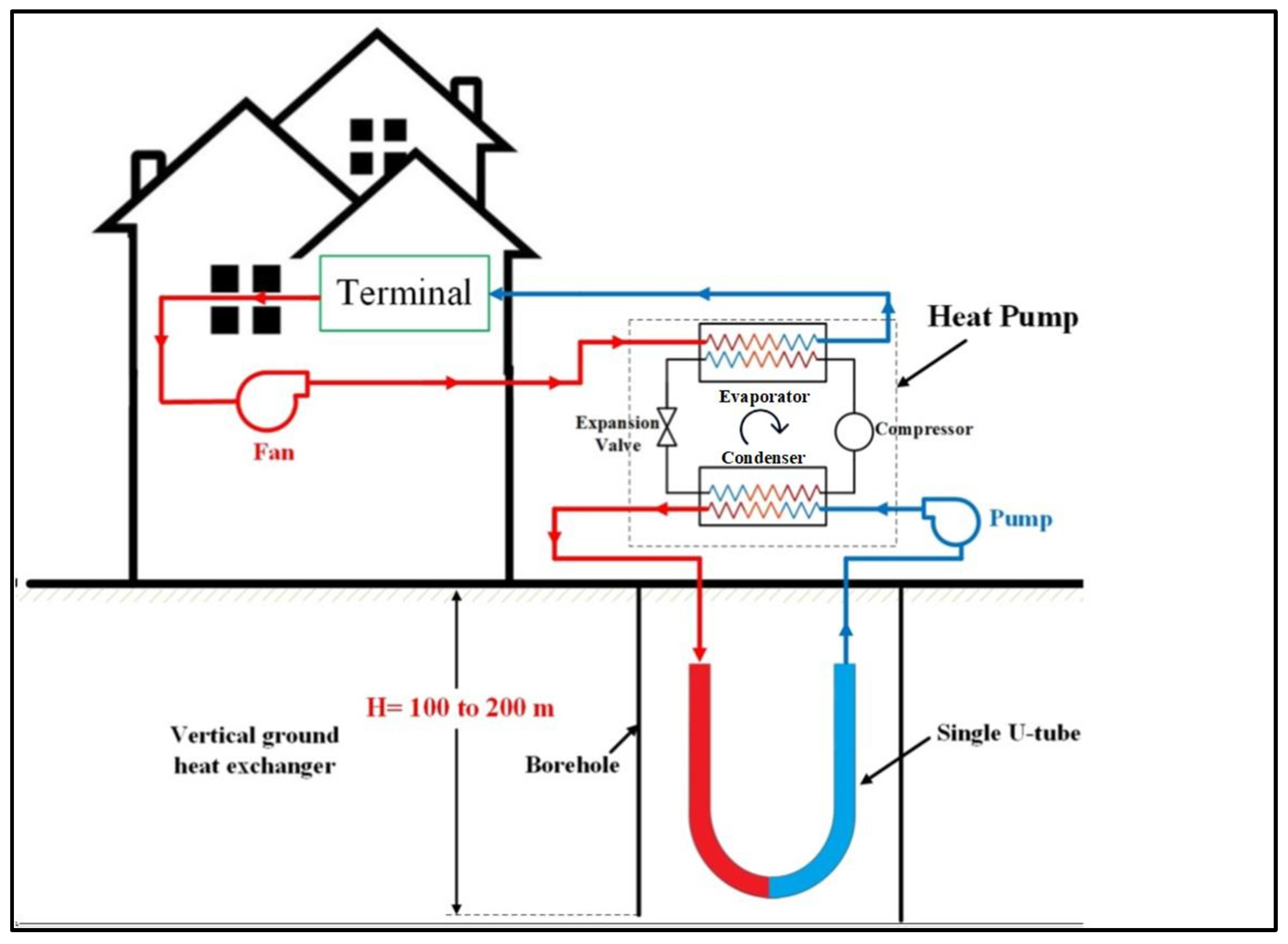
Throughout the summer season, the GHP operates as a cost-effective and environmentally friendly air conditioning solution. It functions by extracting heat from indoors and dispersing it into the ground. Figure 3 illustrates the operational principle of the GHP, which utilizes the cooler temperatures found underground to naturally cool indoor spaces, effectively transferring excess heat into the ground. Conversely, during the colder winter months, the GHP reverses this process. The GHP system comprises a single or multiple heat pumps and one or more vertical-borehole ground heat exchangers (VBGHX), connected to facilitate the exchange of thermal energy between the ground and buildings. The heat pump consists of five essential components: a compressor, an expansion valve, an evaporator, a condenser, and a reversing valve. Additionally, it incorporates various accessories such as pipes, a fan within the air condenser, and control units. Figure 3 illustrates the GHP in the cooling cycle option. It can be seen that there are three loops: (a) air loop through which the air flows between the evaporator of the HP to the distribution units inside the conditioned space, (b) water loop through which the water circulates between the GHE and the HP, and (c) the internal HP loop through which the refrigerant circulates between the evaporator and condenser via the compressor and the expansion valve. The hot air leaving the conditioned space passes inside the air loop through to the evaporator, where it releases its heat energy to the refrigerant. The cooled air then flows to the internal distribution units inside the building, effectively cooling the space. Meanwhile, the cold water from the GHE is pumped through the condenser of the HP to absorb heat from the refrigerant. Subsequently, the hot water leaving the condenser flows back to the GHE, where it releases its heat to the ground inside the borehole. The refrigerant works as a catalyst, facilitating heat transfer between the air and water loops.
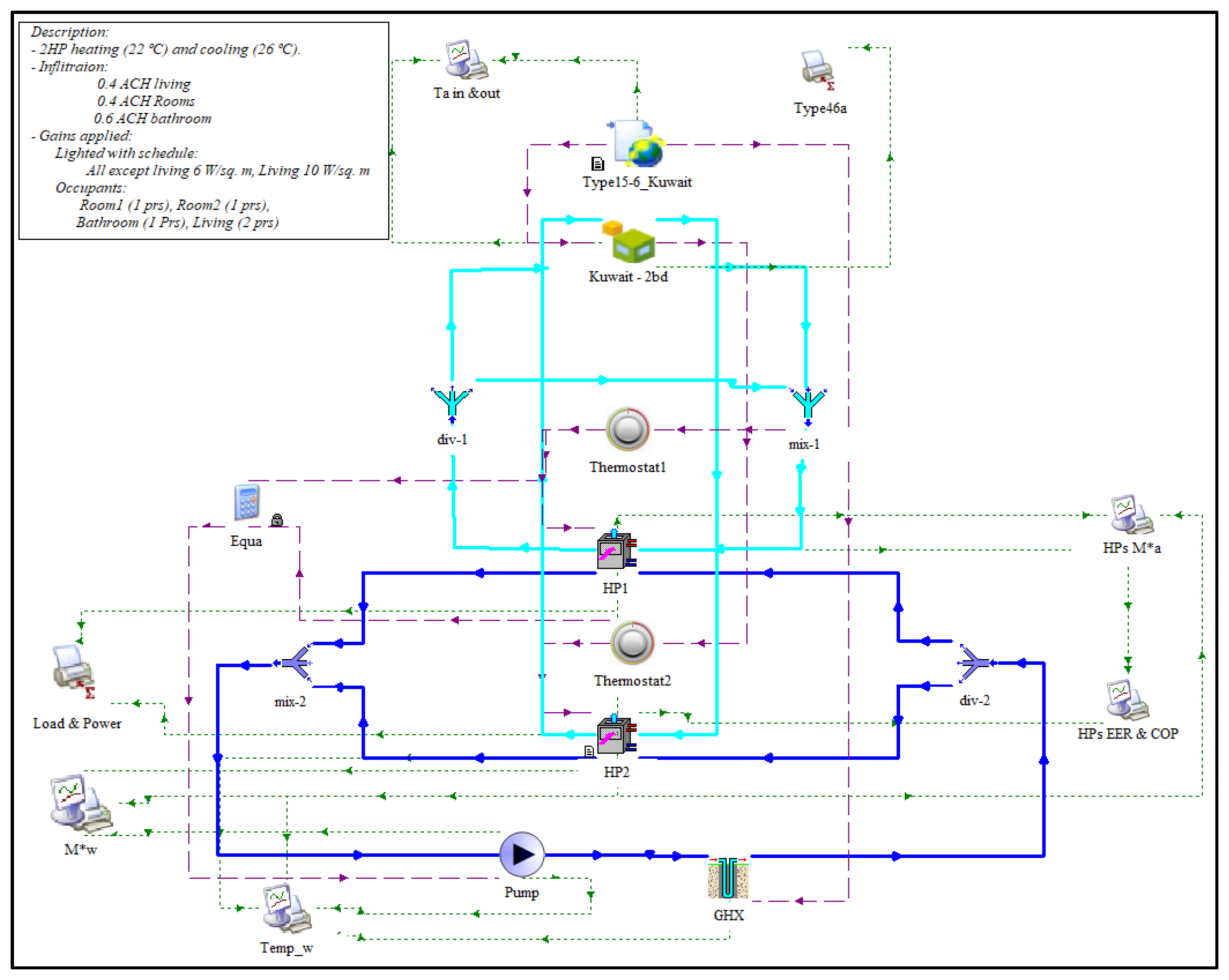
The GHP system employed in this study was modeled using TRNSYS v18 software, as depicted in Figure 4. It comprises various components, including the building model, the Kuwait weather data file, two identical heat pumps (HP), each controlled by a separate thermostat, vertical-borehole ground heat exchangers (VBGHX), pumps, mixers, and dividers. Kuwait weather data from the Meteonorm weather database was integrated into TRNSYS for simulation purposes. HP1 is tasked with conditioning the two bedrooms, while HP2 serves the living area. The divider was employed to distribute the air from HP1 to each of the bedrooms, while the mixer combined air from each bedroom and directed it back to HP1. The use of two separate heat pumps was chosen to ensure operational continuity in case of a potential breakdown of one of the heat pumps. To optimize energy usage, the water pump operates only when one or both of the heat pumps are active. The HPs deactivate when the monitored temperature by the thermostats falls between the set cooling and heating temperatures (22 °C and 26 °C). Key parameters utilized in the model are outlined in Table 3.
Given that all apartments share identical geometry and construction materials, simulations were conducted for three apartments: one intermediate-floor apartment (IFA), the top-floor apartment (TFA), and the ground-floor apartment (GFA). The IFA serves as a representative model for all apartments between the TFA and GFA, as they have identical boundary conditions for their roofs and floors. The outdoor air temperature and the ground temperature were considered as the boundary conditions for the TFA roof and the GFA floor, respectively.

4. HP Governing Equations

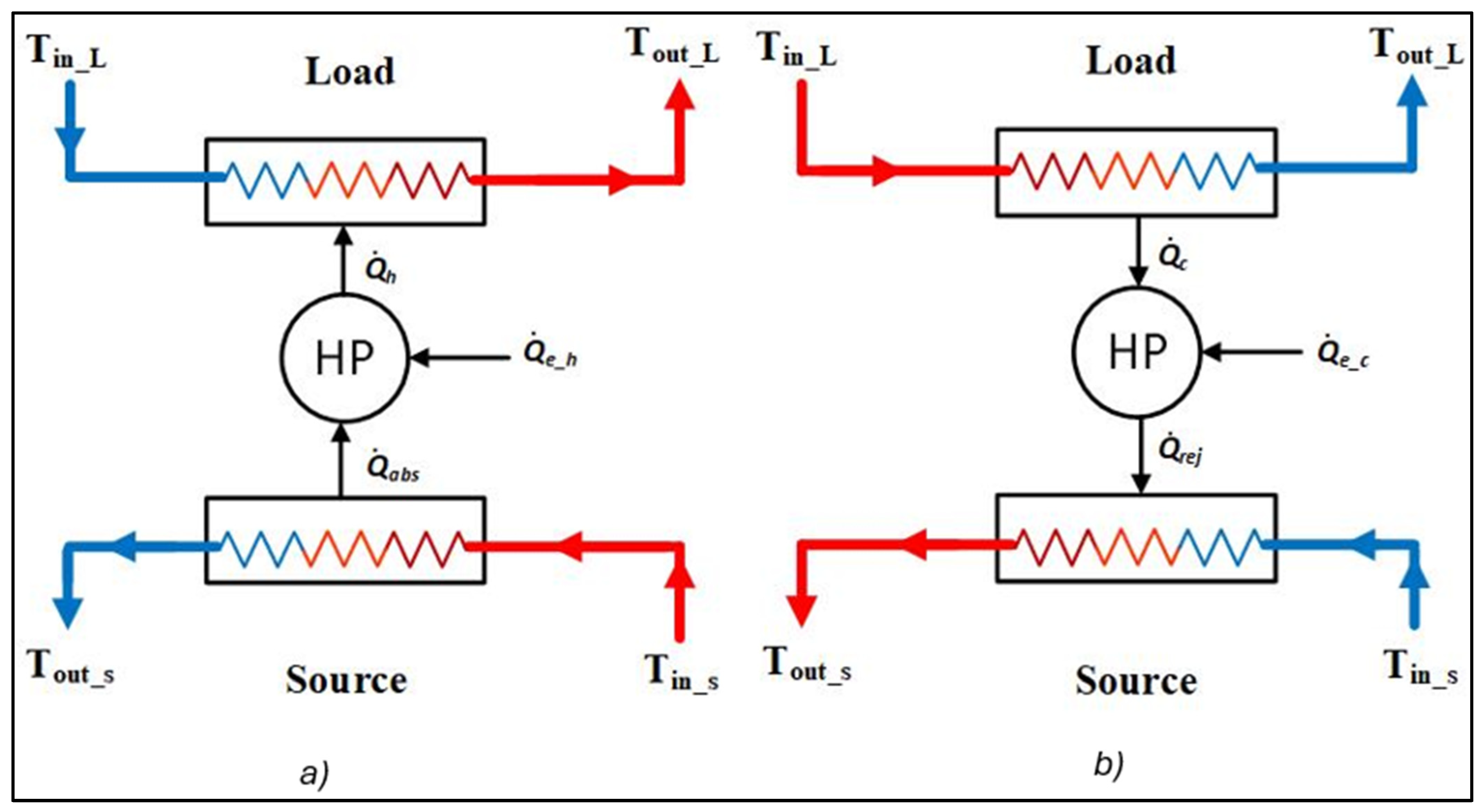
Based on the illustration depicted in Figure 5, the governing equations for the heating and cooling cycles can be written as follows, starting with the heating cycle:
COP h = Q ˙ h Q ˙ e _ h
where COP h is the coefficient of performance for the heating cycle, Q ˙ h is the heating load, and Q ˙ e _ h is the required electric power for heating.
Q ˙ abs = Q ˙ h Q ˙ e _ h
where Q ˙ abs is the absorbed heat by the ground-source liquid.
Q ˙ abs = s CP s T in _ s T out _ s
where s , CP s , T in _ s , and T out _ s are the mass flow rate, the specific heat capacity, and the inlet and outlet temperatures of the ground-source fluid, respectively.
T out _ s = T in _ s Q ˙ abs s CP s
Q ˙ h = L CP L T out _ L T in _ L
where L , CP L , T in _ L , and T out _ L are the mass flow rate, the specific heat capacity, and the inlet and outlet temperatures of the air of the conditioned zones, respectively.
T out _ L = T in _ L + Q ˙ h L CP L
For the cooling cycle:
COP c = Q ˙ c Q ˙ e _ c
where COP c is the coefficient of performance for the cooling cycle, Q ˙ c is the cooling load, and Q ˙ e _ c is the required electric power for cooling.
Q ˙ rej = Q ˙ c + Q ˙ e _ h
where Q ˙ rej is the rejected heat from the conditioned zones.
Q ˙ rej = s CP s T out _ s T in _ s
T out _ s = T in _ s + Q ˙ rej s CP s
Q ˙ c = L C P L T in _ L T out _ L
T out _ L = T in _ L Q ˙ c L CP L
It is customary sometimes to describe the performance of HVAC systems in terms of the seasonal coefficient of performance (SCOP) and the seasonal energy efficiency ratio (SEER) for the heating cycle and cooling cycle, respectively.
SCOP = t o t a l   h e a t i n g   c a p c i t y   f o r   t h e   h e a t i n g   s e a s o n   kWh t o t a l   e l e c t r i c   e r n g y   i n p u t   f o r   t h e   h e a t i n g   s e a s o n   kWh
S C O P = Q h Q e _ h S e a s o n
SEER = t o t a l   c o o l i n g   c a p c i t y   f o r   t h e   c o o l i n g   s e a s o n   BTU t o t a l   e l e c t r i c   e r n g y   i n p u t   f o r   t h e   c o o l i n g   s e a s o n   Wh
SEER = Q c Q e _ c S e a s o n

5. Results and Discussion

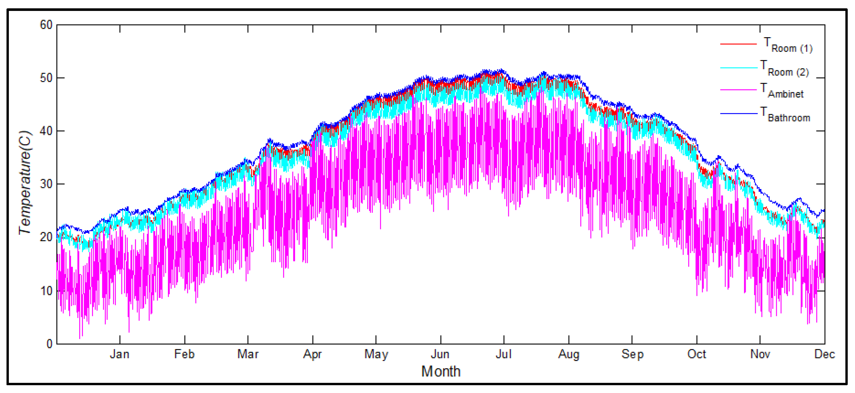
Figure 6 shows the outside air temperature and the indoor temperatures in each zone of IFA before activating the HVAC system. The graph shows that the outside temperature peaks at 48 °C in the summer months and plunges to below 10 °C in January and December. The graph also shows that the temperature inside each of the zones is floating out of control. It is imperative that some sort of HVAC system be installed to keep the condition inside the apartment at a comfortable level. In this study, we proposed an HVAC system based on GHP modeled on TRNSYS. To achieve this objective, the simulation was done in two stages: firstly, using the energy rate control (ERC) model, and secondly, using the temperature level control (TLC) model.

5.1. Energy Rate Control (ERC) Model

To approximate the appropriate size of the HVAC system needed to regulate the indoor temperature to a comfortable level, TRNSYS offers a simulation feature called the energy rate control (ERC) model. Notably, this model operates irrespective of the type of HVAC system employed. By considering factors such as building attributes, external weather conditions, and desired indoor settings, the model calculates instantaneous cooling and heating loads over the entire year. Additionally, it determines peak power requirements and the necessary amount of energy that needs to be extracted or added to attain the desired conditions within the conditioned zones.
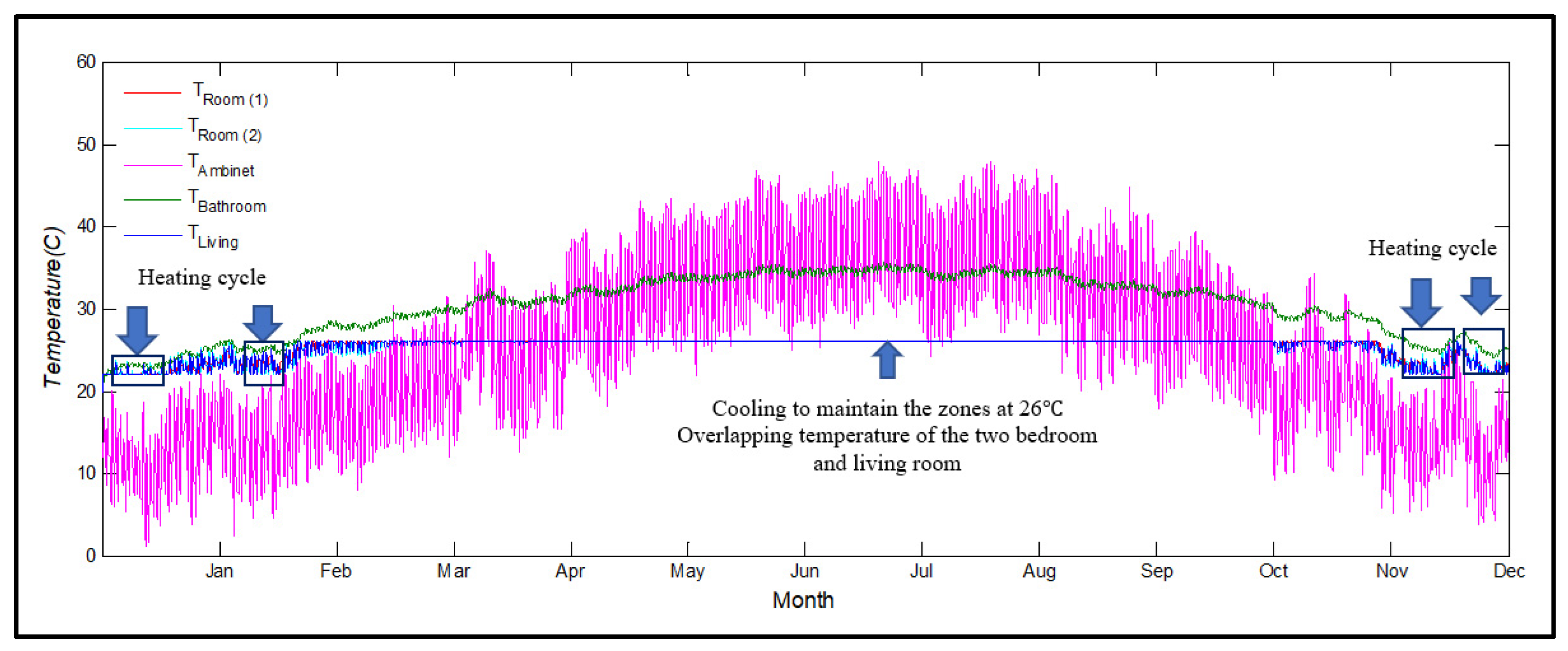
In this investigation, we utilized the ERC model on the building outlined in Section 2, coupled with Kuwaiti weather data. The model integrates external weather conditions, construction material properties, and desired indoor temperatures to resolve the energy balance equations for each thermal zone. This process enables the determination of cooling and heating loads. Figure 7 illustrates the outcomes of implementing the ERC model, which aimed to maintain temperatures within a specific range in different areas of the house. Specifically, the living room and other bedrooms were targeted to be kept at 22 °C and 26 °C during heating and cooling cycles, respectively, while the temperature in the bathroom was allowed to fluctuate. The graph depicts instances where heating was necessary in January and December, while cooling was required for most days throughout the rest of the year.
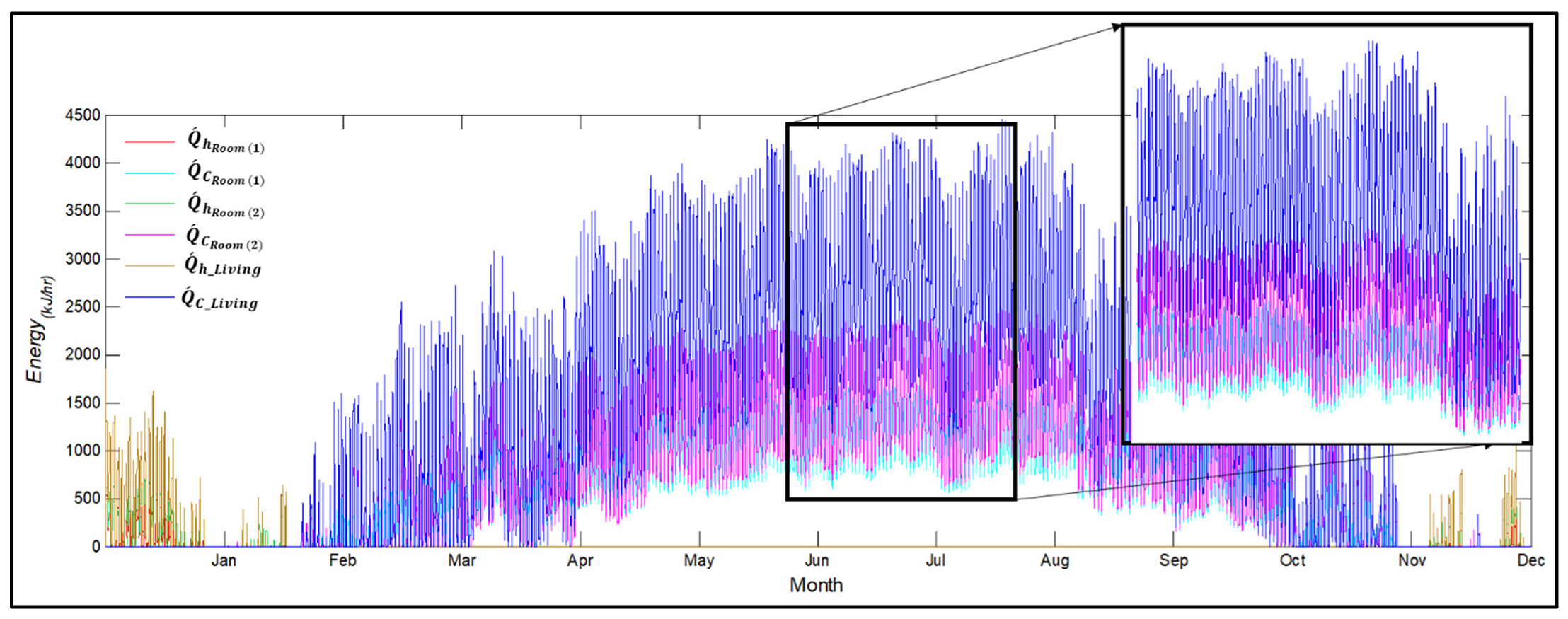
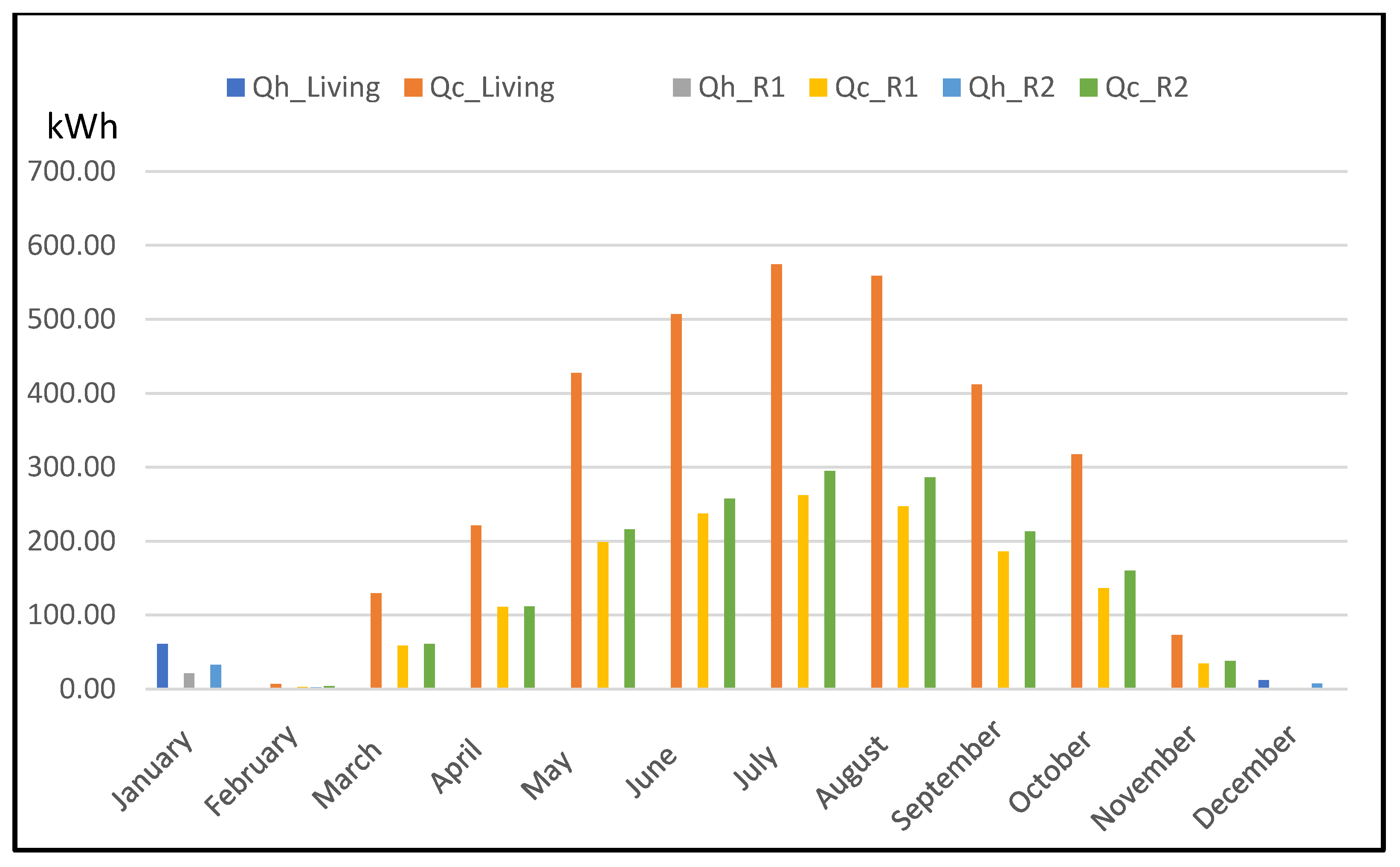
In Figure 8, the instantaneous heating and cooling loads over the entire year are presented. The peak cooling capacities of the HPs, reaching approximately 4460 kJ/h and 2470 kJ/h for the living room and the other two bedrooms, respectively, are observed in August. Similarly, peak heating capacities of around 1850 kJ/h and 1740 kJ/h occur in the living room and bedrooms, respectively, in January. Notably, the graph indicates that the cooling load in the living room surpasses that of other zones due to its larger area, increased energy gains, and more extensive window coverage. This further justifies the use of two separate heat pumps instead of a single large HP per apartment. Figure 9 illustrates the monthly total cooling and heating loads in kWh for each zone. The average cumulative annual cooling load amounts to approximately 7126 kWh (equivalent to 125 kWh/m2).

5.2. Temperature Level Control (TLC) Model

After estimating the peak load using the ERC model, the TLC full model shown in Figure 4 was deployed. Similar to the ERC model, the TLC was applied for the same building detailed in Section 2, employing the same weather data. However, unlike the ERC model, TLC relies on the specific HVAC system employed. Its objective is to replicate the functionality of real-world HVAC systems through a mathematical representation of each system component. In this study, the HVAC system of choice was the GHP system, which consists of two heat pumps, two thermostats, a water pump, and a ground heat exchanger. It was decided to assign one heat pump exclusively for the living room and another identical heat pump for the remaining two rooms. These heat pumps were selected to provide slightly higher cooling and heating capacities than those projected by the ERC model. This oversizing was deemed necessary to accommodate occasional temperatures exceeding 48 °C and the potential for higher heat gains and infiltration rates than the initially assumed values. The parameters used in the heat pumps were taken from a commercial model manufactured by Daikin [23].
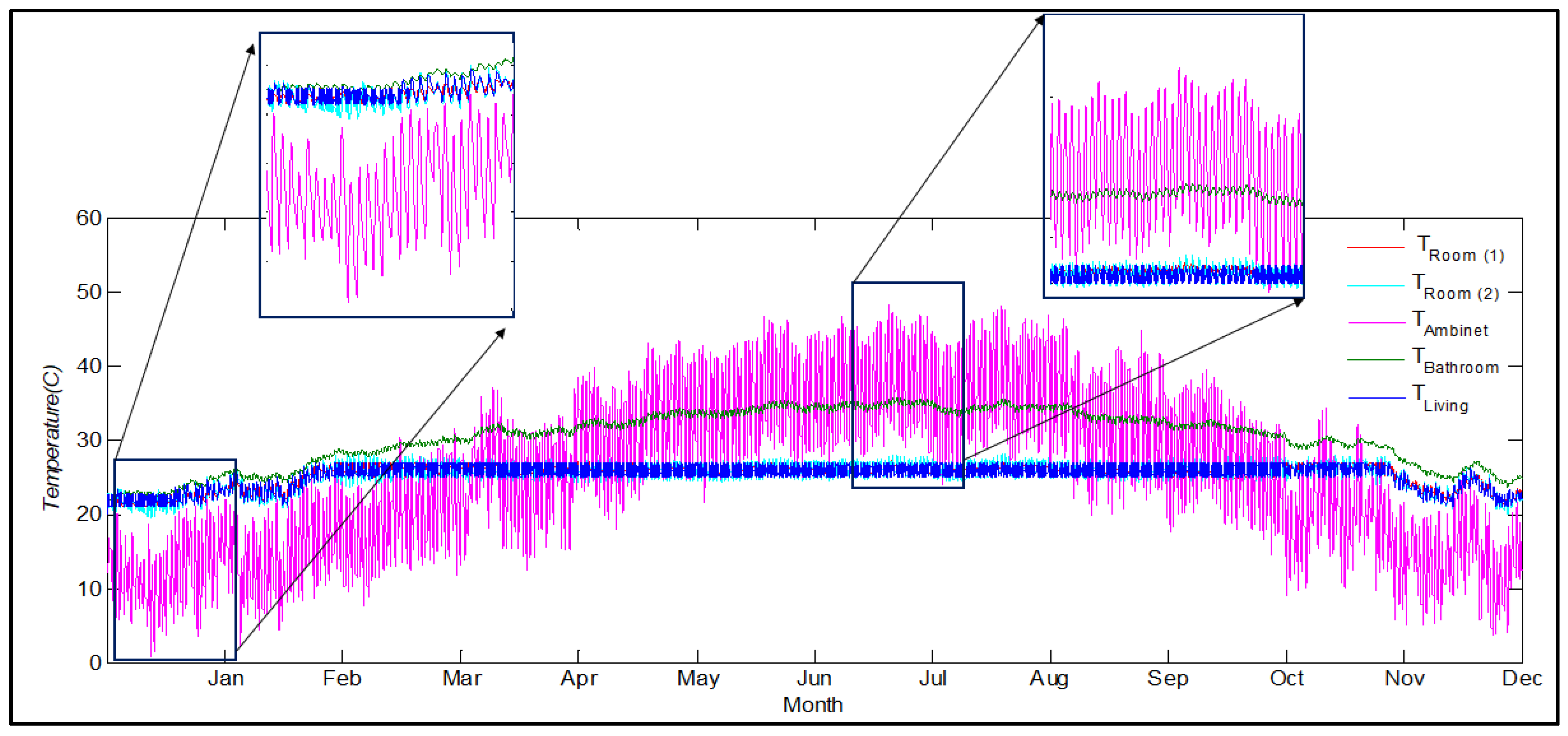
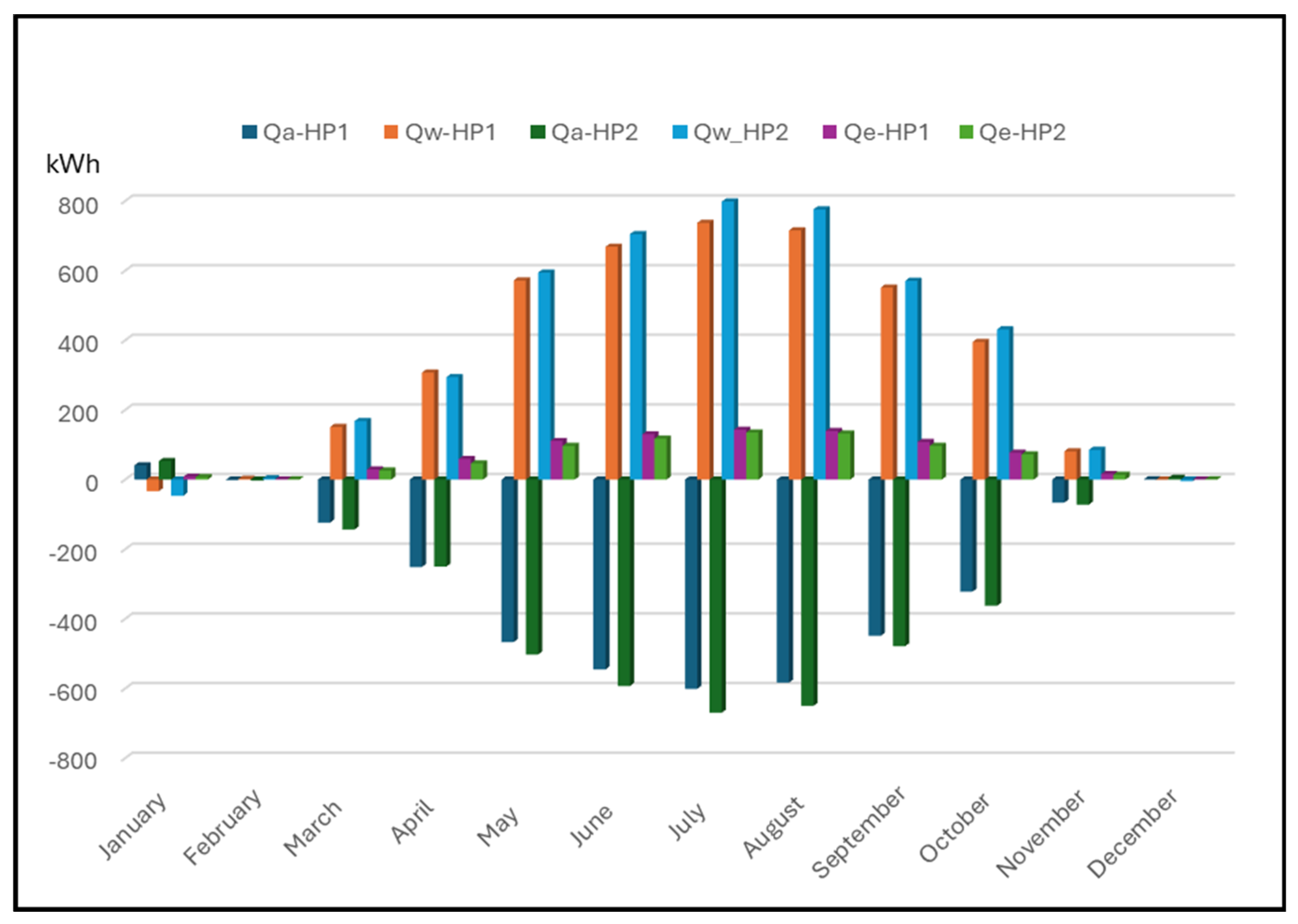
Figure 10 demonstrates the temperature observed in each zone following the implementation of the GHP system. The system effectively regulates the temperature within each zone based on the specific seasonal requirements. During the winter season, the GHP operates in heating mode to elevate the temperature to 22 °C. From around mid-February to the end of November, the cooling cycle is activated to maintain the temperature of the zones at 26 °C. The system deactivates when the temperature falls within the preset limits. The slight deviations around the set temperatures are due to the allowed 2 °C temperature dead band specified in the thermostat. Additionally, it is evident that the temperature oscillation is higher in the two bedrooms compared to the living room, possibly due to a slight oversizing of HP1 relative to the respective loads of bedrooms. This observation is further supported by the higher seasonal energy efficiency ratio (SEER = 17) for HP2 compared to the SEER (SEER = 14) of HP1. The SEER is defined as the ratio of the annual cooling load in BTUs to the electrical power consumed by the HP in Wh. The SEER values in this study were calculated by determining the annual cooling load and electrical power consumption shown in Figure 11.
Figure 11 displays the monthly heat energy transfers for IFA occurring between the air and water loops. The total heat energy removed from the air loop into the water loop and subsequently into the ground (total cooling load) over the course of one year amounted to 3410 kWh and 3724 kWh for HP1 and HP2, respectively. Conversely, the heating load throughout the entire year for both HPs was approximately 100 kWh, primarily in January. The variance in heat transfer between the two loops for the same period is due to heat loss or gain to or from the surroundings. The corresponding annual electrical energy consumption was around 820 kWh for HP1 and 745 kWh for HP2.
It should be noted here that the most expensive part of implementing a GHP is the drilling of vertical boreholes, and hence it may not be a feasible option for a single apartment. Therefore, it would make much more sense to apply such a system to a multi-floor apartment block. The good news is that the above-mentioned simulation, although conducted on a single intermediate-floor apartment (IFA), can be easily scaled up to simulate a multi-floor apartment block. The only variation lies in the boundary conditions of the top-floor apartment’s (TFA) roof and the ground-floor apartment’s (GFA) floor. The roof of the TFA is exposed to the outside air, and hence the ambient temperature was considered for its boundary condition. Likewise, the ground temperature was assumed as the boundary condition for the floor of the GFA. The ground temperature was assumed to be constant throughout the year at 25 °C. This assumption was based on temperature measurements of soil profiles at depths ranging from 5 cm to 100 cm at four distinct locations in Kuwait between 2007 and 2009. The average temperature for these depths across all four locations was determined to be 25.8 °C [24].
Figure 12 illustrates the cooling and heating loads, as well as the electric power consumption of the TFA and GFA in comparison to the IFA. The TFA exhibits the highest cooling and heating loads (Qc = 7305 kWh and Qh = 228 kWh), followed by the IFA (Qc = 7134 kWh and Qh = 100 kWh), and then the GFA (Qc = 6917 kWh and Qh = 81 kWh). Similarly, the electric energy consumption for the three apartments follows the same pattern at Qe_c equals 1587, 1551, and 1503 kWh for cooling, and Qe_h equals 36, 16, and 13 kWh for heating, respectively. The corresponding peak cooling load of 2606 W (45 W/m2) was found to take place in TFA during the month of July. The variance in cooling and heating capacities, and consequently the electric energy consumption, between the TFA and GFA compared to the IFA is attributed to the increased heat transfer rate from the roof to the TFA and the floor of the GFA, in both directions, contingent upon the season.
As mentioned earlier in this investigation, we considered an apartment block consisting of six floors, with one apartment per floor, for the sake of simplicity. Table 4 outlines the combined cooling and heating capacities for both pumps as well as the electricity usage for a typical apartment block. The table shows a total cooling load of 42,758 kWh and a corresponding electric power consumption of 9294 kWh (27 kWh/m2) for the entire apartment block. It can also be seen that the total heating load and its associated energy consumption for the heating cycle are both insignificant in comparison with the cooling cycle.
The results presented in Table 4 are deemed reasonable when compared to data published in the existing literature. For example, the Energy Conservation Code issued by the Ministry of Electricity and Water—Kuwait, 2018 specifies that the maximum allowable power density for water-cooled chillers for residential buildings is 50 W/m2, while for conventional A/C units, it should not exceed 55 W/m2. Our study indicates that the peak cooling load resulting from simulating the top-floor apartment amounted to a power density of 45 W/m2, which falls below the maximum limit set by the Ministry of Electricity and Water (MEW).
Furthermore, in a survey reported by Jaffar et al. [25], covering 170,815 apartments in Kuwait, it was found that the average annual electrical energy consumption for all purposes per square meter equates to 127 kWh/m2. Assuming that 70% of this energy is utilized for space cooling [4], this results in 88 kWh/m2. However, our study, as derived from Table 4, yielded a significantly lower value of 27 kWh/m2. This disparity could be attributed to the higher thermostat setting of 26 °C adopted for the cooling cycle in our study, compared to the average thermostat setting of 22.7 °C in most Kuwaiti households, as reported in a survey by [26]. The 3.3 °C temperature difference in thermostat settings as well as the kind of U-values for the construction materials used in the simulation, combined with the superior efficiency of geothermal heat pumps over conventional air conditioning systems, could account for the lower figures observed in our study.
The subsequent step involved determining the optimal number of boreholes required per apartment and subsequently establishing the total borehole count needed for the entire apartment block. This parametric assessment focused on the TFA due to its extreme cooling and heating loads in comparison with other apartments. Figure 13 illustrates the maximum water temperature exiting the HPs and the GHE, along with the air temperature of the three conditioned spaces during August, for varying numbers of boreholes. The graph depicts a decrease in the temperature of the water exiting GHE (T_GHX) and HP temperatures (Tw_HP1 and Tw_HP2) as the number of boreholes increases from one to three. Conversely, the temperatures of the conditioned spaces experienced a slight drop when transitioning from one to two boreholes but remained constant for three boreholes. This suggests that increasing the borehole count beyond two would have a negligible impact on the conditioned space temperatures. Consequently, it was deduced that each apartment requires two boreholes, resulting in a total of twelve boreholes with the specs mentioned in Table 2 for the entire apartment block.
Based on the preceding discussion, geothermal energy systems, particularly GHP, show significant promise for adoption in Kuwait. As far as the authors are aware, there are no documented instances of geothermal energy utilization in Kuwait for any purpose. GHPs could not only serve a crucial role in cooling and heating residential and commercial buildings but also may prove beneficial for agricultural facilities such as greenhouses as well as dairy and poultry farms in Kuwait, particularly during the scorching summer months when access to grid power may be limited. Given the prevalence of sunny days throughout the majority of the year, the full advantage of GHP technology in Kuwait would be further accentuated when coupled with a PV-solar system, ultimately reducing reliance on fossil fuels. Furthermore, since the U-values employed in this research adhere to the Energy Conservation Code established by MEW for all building types, the normalized values per unit area of the conditioned space derived in this study, such as the power intensity value of 45 W/m2 or the electrical energy consumption of 27 kWh/m2, may serve as useful approximations for various types of residential buildings with similar heat gains.
GHP technology offers several advantages over conventional air conditioning systems, including lower operational costs, higher energy efficiency, and consequently, reduced environmental impact. According to the Environmental Protection Agency (EPA), GHP systems have the potential to reduce heating costs by up to 70% and cooling costs by up to 50%. Despite their comparatively higher initial installation costs compared to conventional systems, GHPs can offer payback periods ranging from 5 to 10 years. To validate this statement, we investigated in the next section the use of conventional AC units to cool the same building with the same conditions tested under the GHP system.

5.3. Conventional Air Conditioning (AC) System

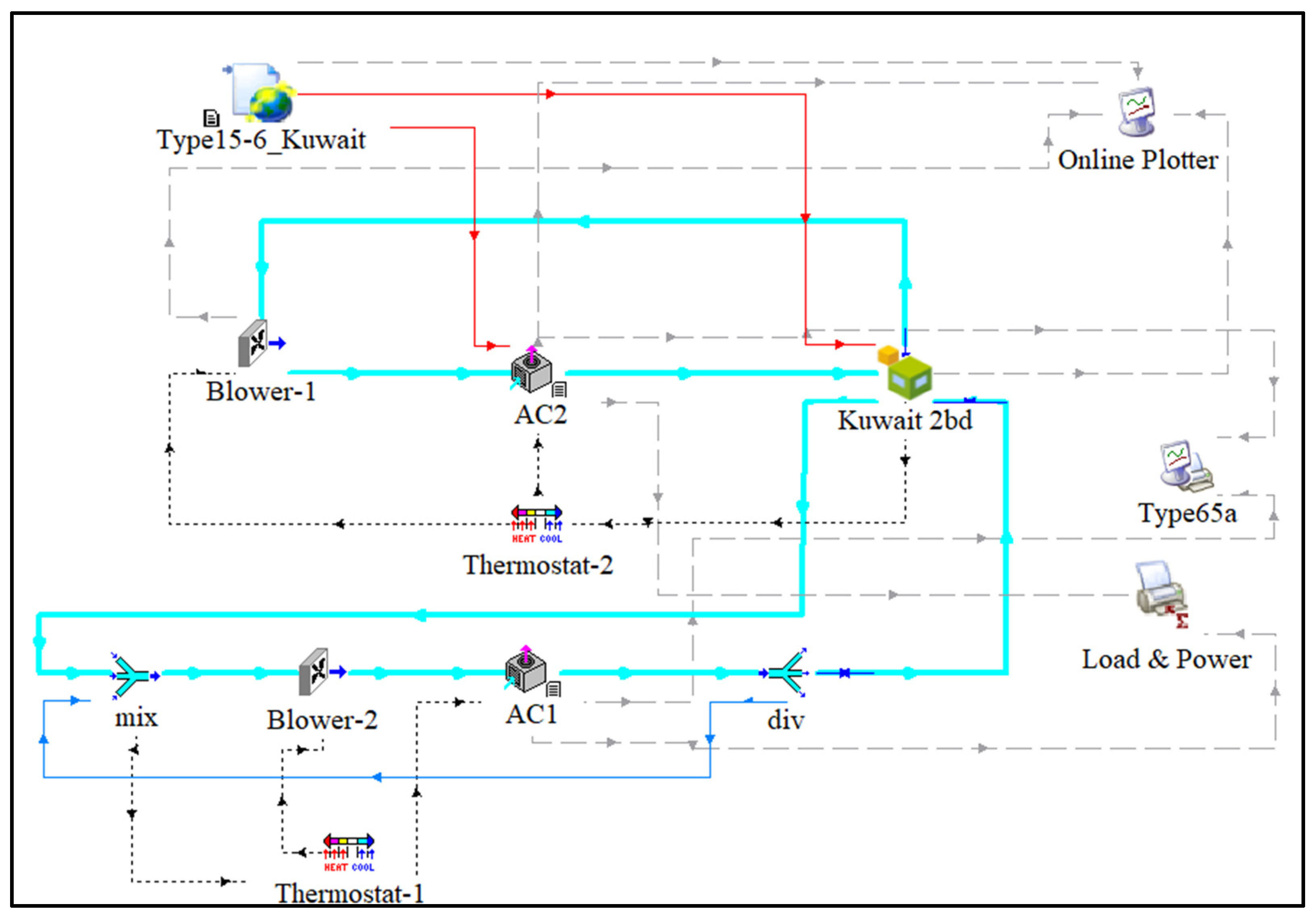
Figure 14 shows the schematic of the conventional AC system utilized for the TFA. As for the GHP system, two identical conventional AC units were used to maintain the conditioned zones at 26 °C with the help of one thermostat for each. The AC1 unit was used to cool the two bedrooms, while the AC2 unit was used to cool the living room.
Figure 15 shows the electric energy consumed by the AC system plotted against the electric energy consumed by the GHP system for the same apartments. Since the AC units used in this study were designed solely for cooling purposes, only the months (March-November) when cooling is needed were considered. It can be seen from the graph that the eclectic energy consumption for the AC system was consistently higher than that of the HP system throughout the cooling season. The simulation results revealed an annual consumption of 1909 kWh and 1487 kWh for the AC system and HP system per apartment, respectively. The difference in annual electric power consumption amounts to 422 kWh (7.4 kWh/m2) for one apartment and 2532 kWh for the entire apartment block, which corresponds to an average reduction of 22% when the HP system is used instead for the AC system. Considering the carbon generation intensity for Kuwait is 0.870 kgCO2/kWh [27], this results in an annual CO2 saving of 376 kg per apartment (6.6 kgCO2/m2) and 2200 kg for the entire apartment block.

6. Conclusions

The discussion highlights the effectiveness of the GHP system outlined in this study in providing comfortable conditions within the described apartments throughout the seasons in Kuwait. The chosen U-values for construction materials, heat gains, and infiltration values are consistent with those defined in the MEW Energy Conservation Code for Buildings and other relevant references given in Section 1. To ensure operational continuity in the event of a potential breakdown, two heat pumps (HPs) were employed instead of a single larger unit for each apartment. This is further justified by the difference in cooling loads between the living room and the other two rooms.
Two TRNSYS simulation models were implemented: the energy rate control (ERC) model and the temperature level control (TLC) model. The ERC model was used to approximately estimate the size of the HVAC system required to maintain the conditioned space at the desired temperature for one of the IFAs. The results revealed a peak cooling load of 4460 kJ/h and 2470 kJ/h for the living room and bedrooms, respectively, observed in July and August. Similarly, peak heating loads of around 1850 kJ/h and 1740 kJ/h occur in the living room and bedrooms, respectively, predominantly in January. Additionally, the ERC model estimated the yearly energy consumption of the HVAC system to be approximately 8000 kWh per apartment.
Conversely, the TLC model employed two heat pumps with a cooling load of 2.58 kW each for each apartment. One thermostat was used for each heat pump to maintain the temperature at 22 °C for heating and 26 °C for cooling. The simulation work was initially conducted on one intermediate apartment and was further extended to the entire apartment block. The required number of GHE boreholes for the apartment block was estimated to be 12. The simulation estimated an annual cooling load of 42,758 kWh for the entire block and 7126 kWh on average per apartment. The heat pumps were operating at SEERs between 14 and 17 BTU/kWh. The annual electric energy consumption for the apartment block was estimated at 9294 kWh (27 kWh/m2) and 113 kWh (0.33 kWh/m2) for cooling and heating cycles, respectively. These figures show that the heating load is insignificant in comparison with the cooling load in Kuwait. Furthermore, the cooling cycle power density was found to be 45 W/m2, meeting the maximum allowed limit of 50 W/m2 set by the MEW Energy Conservation Code. These normalized values per unit area of the conditioned space derived in this study may serve as useful approximations for various types of residential buildings with similar heat gains.
The investigation has also revealed the superior performance of the HP system in comparison with the conventional air condition system. We have shown that the use of the HP system resulted in a 22% reduction in annual electric consumption and an annual CO2 saving of 376 kg per apartment (6.6 kgCO2/m2) and 2200 kg for the entire apartment block.

Author Contributions

Investigation, Y.G., J.F.D., A.M.A. and A.D.; writing—original draft, Y.G. All authors have read and agreed to the published version of the manuscript.

Funding

This research received no external funding.

Data Availability Statement

Data are contained within the article.

Conflicts of Interest

The authors declare no conflict of interest.

Nomenclature

SymbolsDescriptionUnits
ACConventional Air Conditioning Units-
ACHAir Change Per Hour-
BHBorehole-
COPCoefficient of Performance-
CPSpecific Heat CapacitykJ/kg·K
DXDirect Expansion-
EEREnergy Efficiency Rating(Btu/h)/W
ERCEnergy Rate Control-
GFAGround-Floor Apartment-
GHEGround Heat Exchanger-
GHPGeothermal Heat Pump-
GSHPGround-Source Heat Pump-
HPHeat Pump-
IFAIntermediate-Floor Apartment-
  m   ˙ Mass Flow Ratekg/s
MEPSMinimum Energy Performance Standard-
MEWMinistry of Electricity and Water-
PAIPublic Authority for Industry-
PVPhotovoltaics-
Q a Heat Energy Transferred to the Air LoopkWh
Q w Heat Energy Transferred to the Water LoopkWh
Q c ˙ Cooling LoadkW
Q h ˙ Heating LoadkW
SCOPSeasonal Coefficient of Performance-
SEERSeasonal Energy Efficiency RatioBtu/kWh
Ta_HP1, Ta_HP2Air Temperature Leaving HP1 and HP2, respectively°C
TGHETemperature of the Water Leaving the GHE°C
Tw_HP1, Tw_HP2Water Temperature Leaving HP1 and HP2, respectively°C
TFATop-Floor Apartment-
TLCTemperature Level Control-
VBGHXVertical-Borehole Ground Heat Exchanger-
Subscripts:
absAbsorbed-
e_cElectric Energy for Cooling-
e_hElectric Energy for Heating-
LLoad-
R1, and R2Refer to the Conditioned Zones Room1 and Room2, respectively-
rejRejected-
sSource-

References

  1. World Bank. Electric Power Consumption (kWh per Capita)—Kuwait. Available online: https://data.worldbank.org/indicator/EG.USE.ELEC.KH.PC?locations=KW (accessed on 27 January 2024).
  2. Dinc, A.; Taher, R.; Derakhshandeh, J.F.; Fayed, M.; Elbadawy, I.; Gharbia, Y. Performance Degradation of a 43 MW Class Gas Turbine Engine in Kuwait Climate. Int. Res. J. Innov. Eng. Technol. 2021, 5, 108–113. [Google Scholar] [CrossRef]
  3. Darwish, M. Energy efficient Air conditioning: Case study for Kuwait. Kuwait J. Sci. Eng. 2005, 32, 209–222. [Google Scholar]
  4. Electricity, M.O.; Kuwait, W. Energy Conservation Code For Buildings-New-r6-2018. 2018. Available online: https://www.mew.gov.kw/media/f5eezszd/new-r6-2018%D8%A7%D9%84%D8%AA%D9%83%D9%8A%D9%8A%D9%81.pdf (accessed on 27 January 2024).
  5. KWS 1893:2018; Energy Efficiency Labelling and Minimum Energy Performance Requirements for DX Air-Conditioners up to 70,000 BTU/H. Public Authority for Industry (PAI): Kuwait City, Kuwait, 2018.
  6. Ben-Essa, S. Cooling and heating loads in residential buildings in Kuwait. J. Eng. Res. Appl. 2018, 8, 1–14. [Google Scholar] [CrossRef]
  7. Dinc, A.; Gharbia, Y. Global Warming Potential Estimations of a Gas Turbine Engine and Effect of Selected Design Parameters. In Proceedings of the ASME International Mechanical Engineering Congress and Exposition, Proceedings (IMECE), Online, 16–19 November 2020; Volume 8, pp. 1–7. [Google Scholar] [CrossRef]
  8. Fakhreddine, O.; Gharbia, Y.; Derakhshandeh, J.F.; Amer, A.M. Challenges and Solutions of Hydrogen Fuel Cells in Transportation Systems: A Review and Prospects. World Electr. Veh. J. 2023, 14, 28. [Google Scholar] [CrossRef]
  9. Grami, S.; Gharbia, Y. Experimental investigation of new designed solar parabolic trough collectors. In Proceedings of the IEEE International Conference on Industrial Technology, Lyon, France, 20–22 February 2018; pp. 972–977. [Google Scholar] [CrossRef]
  10. Wang, Q.; Zhang, X.; Zhang, H.; Ma, Y.; Zhao, S. Optimization of solar-assisted GWHP system based on the Trnsys model in cold regions. Renew. Energy 2022, 196, 1406–1417. [Google Scholar] [CrossRef]
  11. Montagud, C.; Corberán, J.M.; Ruiz-Calvo, F. Experimental and modeling analysis of a ground source heat pump system. Appl. Energy 2013, 109, 328–336. [Google Scholar] [CrossRef]
  12. Darwish, M. Building air conditioning system using fuel cell: Case study for Kuwait. Appl. Therm. Eng. 2007, 27, 2869–2876. [Google Scholar] [CrossRef]
  13. Al-Homoud, A.A.; Suri, R.K.; Al-Roumi, R.; Maheshwari, G.P. Experiences with solar cooling systems in Kuwait. Renew. Energy 1996, 9, 664–669. [Google Scholar] [CrossRef]
  14. Narayanan, R.; Al Anazi, A.A.; Pippia, R.; Rasul, M. Design Optimization of Solar Desiccant Cooling System for the Climatic Condition of Kuwait. AIP Conf. Proc. 2022, 2681, e020032. [Google Scholar] [CrossRef]
  15. Cui, P.; Yang, W.; Zhang, W.; Zhu, K.; Spitler, J.D.; Yu, M. Advances in ground heat exchangers for space heating and cooling: Review and perspectives. Energy Built Environ. 2024, 5, 255–269. [Google Scholar] [CrossRef]
  16. Eswiasi, A.; Mukhopadhyaya, P. Critical Review on Efficiency of Ground Heat Exchangers in Heat Pump Systems. Clean Technol. 2020, 2, 204–224. [Google Scholar] [CrossRef]
  17. Asim, M.; Dewsbury, J.; Kanan, S. TRNSYS Simulation of a Solar Cooling System for the Hot Climate of Pakistan. Energy Procedia 2016, 91, 702–706. [Google Scholar] [CrossRef]
  18. Jadidi, H.; Keyanpour-Rad, M.; Haghgou, H.; Chodani, B.; Kianpour Rad, S.; Hasheminejad, S.M. Energy and exergy simulation analysis and comparative study of solar ejector cooling system using TRNSYS for two climates of Iran. Heliyon 2022, 8, E10144. [Google Scholar] [CrossRef] [PubMed]
  19. Sun, C.; Ju, X.; Hao, W.; Lu, Y. Research on multi-objective optimization of control strategies and equipment parameters for a combined heating system of geothermal and solar energy in cold and arid regions based on TRNSYS. Case Stud. Therm. Eng. 2023, 50, 103441. [Google Scholar] [CrossRef]
  20. Chargui, R.; Sammouda, H.; Farhat, A. Geothermal heat pump in heating mode: Modeling and simulation on TRNSYS. Int. J. Refrig. 2012, 35, 1824–1832. [Google Scholar] [CrossRef]
  21. Moncef, K. Economic and Social Commission of Western Aria; United Nations Development Account. Promoting Energy Efficiency Investments for Climate Change Mitigation and Sustainable Development: Case Study—Kuwait; UNECR: Geneva, Switzerland, 2015. [Google Scholar]
  22. ASHRAE Standard 62; ANSI/ASHRAE Standard 62.1 and ANSI/ASHRAE Standard 62. ANSI: Washington, DC, USA, 2016. Available online: https://webstore.ansi.org/standards/ashrae/ansiashraestandard62 (accessed on 12 April 2024).
  23. Daikin. Catalog 1113-16 SmartSource® Single Stage Horizontal & Vertical Water Source Heat Pumps, GSH-Horizontal Ceiling, GSV-Vertical Floor, Unit Sizes 007-070 R-410A Refrigerant; Daikin: Minneapolis, MN, USA, 2021. [Google Scholar]
  24. Elmi, A. Soil Profile Temperature as an Indicator for Potential Effects of Climate Change Under Arid Ecosystems of Kuwait. In Proceedings of the 4th IASTEM International Conference, Amsterdam, The Netherlands, 12 November 2015; pp. 82–85, ISBN 978-93-85832-36-9. [Google Scholar]
  25. Jaffar, B.; Oreszczyn, T.; Raslan, R. A framework to evaluate the energy efficiency potential of Kuwaiti homes. WIT Trans. Ecol. Environ. 2014, 186, 25–38. [Google Scholar] [CrossRef]
  26. Al-ajmi, F.F.; Loveday, D.L. Indoor thermal conditions and thermal comfort in air-conditioned domestic buildings in the dry-desert climate of Kuwait. Build. Environ. 2010, 45, 704–710. [Google Scholar] [CrossRef]
  27. International Energy Agency. CO2 Emissions from Fuel Combustion 2012; OECD: Paris, France, 2012. [Google Scholar] [CrossRef]
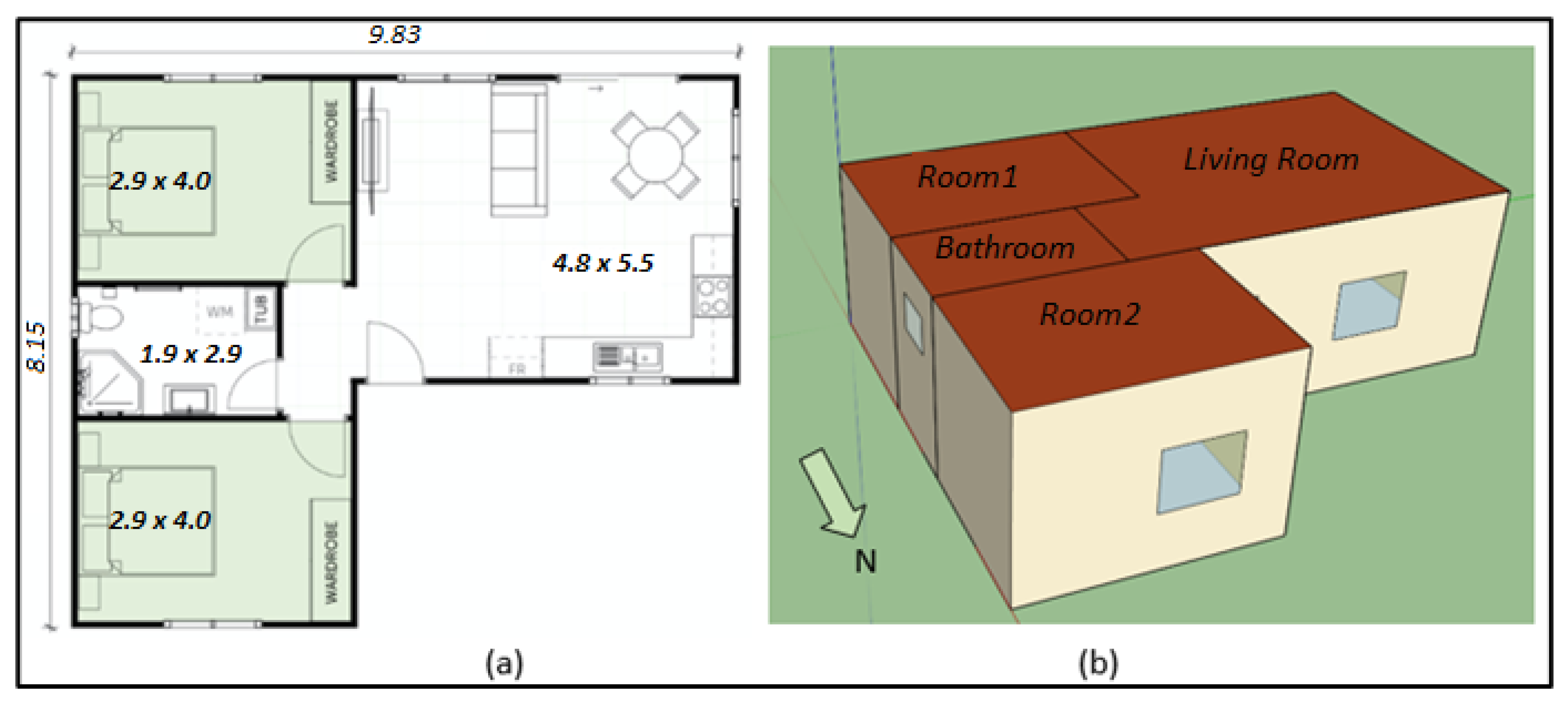
Figure 1. (a) The floor plan of the simulated apartment. (b) The isometric view of the apartment as modeled in Sketchup Pro 2017 software.
Processes 12 00910 g001
Figure 2. Lighting schedule assumed in this study.
Processes 12 00910 g002
Figure 3. Schematic of a closed loop ground-source heat pump (GHP) system.
Processes 12 00910 g003
Figure 4. TRNSYS model for the GHP system employed for heating and cooling of a two-bedroom apartment in Kuwait.
Processes 12 00910 g004
Figure 5. Schematic diagram of a GHP in both (a) heating and (b) cooling cycles.
Processes 12 00910 g005
Figure 6. Shows the temperatures inside all the zones when the HVAC system is switched off.
Processes 12 00910 g006
Figure 7. The temperature variation inside each zone in addition to the outside air temperature using ERC.
Processes 12 00910 g007
Figure 8. The instantaneous heating and cooling loads for the two bedrooms and the living area.
Processes 12 00910 g008
Figure 9. The monthly heating and cooling loads for the two bedrooms and the living area.
Processes 12 00910 g009
Figure 10. The temperature variation in each of the zones because of the implementation of the GHP system.
Processes 12 00910 g010
Figure 11. The monthly energy exchange between the air and water loops for the apartment.
Processes 12 00910 g011
Figure 12. The annual cooling and heating loads along with the corresponding electric power consumption for TFA, IFA, and GFA.
Processes 12 00910 g012
Figure 13. The maximum water temperature exiting the HPs and the GHE, along with the air temperature of the three conditioned spaces during August for different boreholes.
Processes 12 00910 g013
Figure 14. TRNSYS model for the conventional air conditioning system employed for cooling a two-bedroom apartment in Kuwait.
Processes 12 00910 g014
Figure 15. The electric energy consumption for the conventional AC system and the HP system.
Processes 12 00910 g015
Table 1. Surface types and their related specs for the living room as implemented on TRNBuild.
Surface TypeConstruction TypeArea (m2)Category
WallHollow_Brick16.50External
WallExt_Door2.00External
WallHollow_Brick16.50External
FloorBND_Ceiling28.49Boundary
RoofBND_Ceiling28.49Boundary
WallHollow_Brick14.40External
WallHollow_Brick8.70Adjacent (Room1)
WallHollow_Brick3.30Adjacent (Room2)
Table 2. The properties assigned to walls, windows, the ceiling, and the floor.
SurfaceMaterial TypeU-Value (W/m2·K)Thickness (m)
WallsHollow bricks0.5530.223
FloorBND_Ceiling (Prg. Default)0.1480.506
CeilingBND_Ceiling (Prg. Default)0.1480.506
WindowsDouble-Pane Glass (Prg. Default)1.1
Table 3. The model’s key components and parameters.
DescriptionSpecification
ThermostatSimple room thermostat: Type166
   Cooling set temperature   26 °C
   Heating set temperature   22 °C
   Temperature deadband   2 °C
Convective Heat Transfer CoefficientIndoor/Outdoor, 11/64 [kJ/h m2·K]
Heat pumpWater source HP: Type919
   Rated heating capacity   2.90 kW (9900 BTU/h)
   Rated heating power   0.612 kW
   Rated cooling capacity   2.58 kW (8800 BTU/h)
   Rated cooling Power   0.424 kW
Ground Heat ExchangerVertical U-Tube: Type557
   Number of boreholes   2 per apartment
   Depth/borehole spacing   100 m/4.8 m
   Soils storage volume   4000 m3
   Storage thermal conductivity   4.68 (kJ/kg)/m·K
   Storage heat capacity   2016 kJ/m3/K
Water PumpSingle speed: Type114
Simulation Run Time8760 h: 1 January 00:00 to 31 December 24:00
Time Step7.5 min
Table 4. The total cooling and heating capacities along with the electric energy consumption for the apartment block.
Floor #Cooling Load (Qc) in kWhHeating Load (Qh) in kWhElec. Eng. Cooling (Qe_c) in kWhElec. Eng. Heating (Qc_h) in kWh
6 (TFA)7305228158736
 57134100155116
 47134100155116
 37134100155116
 27134100155116
1 (GFA)691781150313
Total42,7587099294113
Disclaimer/Publisher’s Note: The statements, opinions and data contained in all publications are solely those of the individual author(s) and contributor(s) and not of MDPI and/or the editor(s). MDPI and/or the editor(s) disclaim responsibility for any injury to people or property resulting from any ideas, methods, instructions or products referred to in the content.