Abstract
The cement strength between the cement and the formation is a key factor in determining the cementation sealing capacity. In the shale formation, due to the organic matter content, the cementing quality between the formation and the cement ring is poor, which affects the quality of cementing. It is easy to cause problems such as annulus pressure. To improve the quality of cementing, this paper investigates the effect of amino silane coupling agents, vinyl silane coupling agents and aluminium–zirconate coupling agents on the interface cementation of rock and cement under different conditions. Meanwhile, the effects of different coupling agent compounding on improving the cementation interface cement strength under different temperature and concentration conditions were investigated. This led to the development of a composite interface enhancer. The composite interface enhancer can improve the bond strength between cement and rock by 189.22%. A preflush fluid system was developed to effectively improve the cementation strength of mud shale formations, and its performance was evaluated. The density of the preflush fluid system is 1.15 g·cm−3, and it has good rheology, settlement stability, and filtration loss. In addition, it improves the cementing interface cementing strength between the cement and shale formation.
1. Introduction
1.1. Motivation
The cementing quality of the cementing second interface is the key factor to determining the quality of the cementing sealing system [1]. A cementing second interface cementing system mainly consists of cement ring, mudcake and formation [2]. In the drilling process, the formation condition is complicated. This makes the environment of the cementing second interface more complicated than the first interface, and the cementing condition is weaker [3]. It is easy to have problems such as annulus with pressure. The annular pressure will not only affect the recovery effect of oil and gas wells but also seriously affect the production safety [4]. According to the field data, the proportion of shale gas wells with annulus pressure is much higher than the proportion of normal gas wells with annulus pressure [5]. It is of practical significance to explore a method to improve the sealing capacity of cement rings through the research and development of a formation–cement ring interface enhancer.
The shale is a kind of ultra-low porosity and ultra-low permeability sedimentary rock that is mainly composed of clay minerals such as montmorillonite, with various pores and microfractures developed [6,7,8]. In the cementing process, it is important to ensure the optimal production rate and avoid problems such as annular pressure caused by the upward migration of oil and gas at the formation–cement ring interface of the cementing process. In many oil and gas-bearing basins such as Tarim Basin and Sichuan Basin in China, shale can not only be used as a source rock to generate oil and gas but also as a cap rock to prevent oil and gas from escaping upward because of its unique physical and chemical properties of low porosity and low permeability [9]. It is necessary to ensure a good cementation between the shale caprock and the cement ring so as to ensure the effective sealing performance of the cementing section and prevent oil and gas from flowing along the formation–cement ring interface to the upper annulus. The shale formation rocks contain organic matter, which results in poor cementation quality between the formation and the inorganic cement. The mud shale was formed with a large amount of organic matter deposited, and the organic matter pores and clay mineral pores are mainly distributed in the mud shale cover. This leads to the uneven distribution of hydrophilic and lipophilic interfaces [10]. Cement slurry is an inorganic working fluid, which has poor cementing performance with the lipophilic interface. Therefore, improving the sealing quality of the formation–cement ring interface in cap cementing and preventing oil and gas channelling in the annulus have become urgent issues to be addressed.
1.2. Literatures Review
At present, there have been many studies on improving the quality of cementing secondary interface sealing. MTC (mud cake to agglomerated cake) technology is an early cementing interface enhancement technology researched and applied in China. Many experts, such as Huang, Bu, etc., have conducted research on its mechanism and formulation [11,12,13]. This technology can realise the whole curing cementation of cement and mud cake so as to improve the cementation strength of the cementation interface [13]. Most of the current research in the interface enhancers is applied to drilling muds. Many experts and scholars, such as Xie, Sun and Zhang, have developed a variety of interface enhancers for application in drilling mud [14,15,16,17,18,19]. The common feature is that the interface enhancers are added to the drilling mud, which reacts with the original components of the mud cake. The mud cake becomes dense, tough and resistant to scouring and strong [17]. This improves the cementation interface bond strength, and these interface enhancers are mostly targeted at formations such as sandstone where a large amount of mud cake remains after drilling. However, the interface enhancers specifically designed for shale formation, where the amount of filtration loss is small and the mudcake is thin or even non-existent, have not been studied yet.
In cementing engineering, the mud cake remaining in the well wall can be effectively removed by adding specific chemical treatment agents to the preflush fluid [16]. Many scholars at home and abroad have researched efficient cleaning prelude liquid systems for different kinds of drilling muds. Through the emulsification, chelation, penetration and other effects of specific chemical treatment agents in the system, the mud cake can be removed quickly [20,21,22,23]. However, there are few studies on the application of interface enhancer in the preflush fluid system to further improve the cement strength of the second interfaces.
1.3. Contribution
In summary, based on its composition and structural characteristics, the shale has poor cementation quality with the cement. However, there is a lack of research on the cementing qualities of shale caprocks and cement. There is insufficient understanding of this aspect. Therefore, it is necessary to develop the interface enhancers for shale caprocks. In this study, a set of preflush fluid systems was constructed through the development of interface enhancers between the formation and cement. It can improve the cementation strength of the second interface and provide new ideas and countermeasures for the interface enhancement technology. It can also improve the cementing strength of the cementing interface of shale formations, laying the foundation for effectively guaranteeing the safety of oil and gas production and increasing the recovery rate of oil and gas.
2. Materials and Methods
2.1. Materials and Equipment
The materials and chemical reagents involved in this study are shown in Table 1.

Table 1.
Main experimental materials and reagents.
The main instrumentation used in this study to formulate the cement paste, the preflush fluid and performance test are shown in Table 2.
Table 2.
Main experimental instruments and equipment.
2.2. Cementing Strength Test of the Formation–Cement Ring Interface
The next procedure was followed in the cementing tests for the formation–cement ring interface. The flow of the experiment is shown in Figure 1 below.
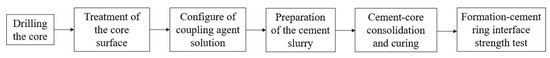
Figure 1.
Main flow chart of the interface cementation experiment.
- (1)
- Drilling the core
The core taken from the site was drilled in the laboratory, and the cutting mechanism was used to make the size (25 mm × 25 mm) for the experiment. The core specimen is shown in Figure 2.
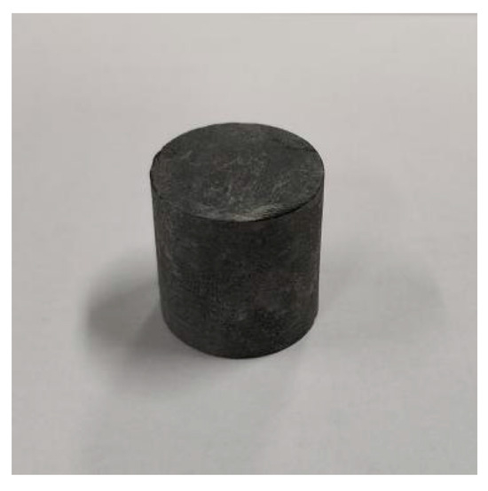
Figure 2.
Core specimen.
- (2)
- Configuration of coupling agent solution
Water was used as a dispersant, adding 10% anhydrous ethanol and stirring. Subsequently, we added the coupling agent drop by drop into the low speed mixing solvent, continuing to stir at low speed for 5 min, until it was fully mixed. When the A silane coupling agent solution and LD aluminium–zirconium coupling agent solution were configured, it was necessary to add the acetic acid while stirring, and we adjusted the solvent PH to 3–5 to improve its dissolution. Concentrations used in the article are mass concentrations. The unit is %.
- (3)
- Treatment of the core surface
The amount of precursor fluid needs to meet the requirement of turbulent flow contact time to ensure top-off efficiency. Generally, it can be considered at 10 min. Therefore, in this experiment, the natural mud shale core was immersed in the coupling agent for 10 min. The coupling agent was allowed to fully react with the natural core.
- (4)
- Preparation of the cement slurry
The conventional cement slurry was prepared according to the standard “Test method for Oil well cement” (GB/T 19139-2012 [24], which the water–cement ratio was 0.44;
- (5)
- Cement core consolidation and curing
The treated core was put into the steel ring mould to simulate the mud shale formation, and the cement slurry was injected into the mould for maintenance so as to cement and core consolidation. In this experiment, three representative temperatures were considered: medium–low, medium, and high. The different curing temperatures were set for each group: 70 °C, 90 °C and 150 °C. The strength of the cement needs to be fully developed when cement cementing logging. The waiting time for setting is normally not less than 48 h. Therefore, the curing time is 48 h.
- (6)
- Formation–cement ring interface strength test
The cured specimen is shown in Figure 3. After solidified cement slurry, the press was used to test the formation–cement ring interface’s shear cementation strength. The schematic diagram of the experimental device is shown in Figure 4.
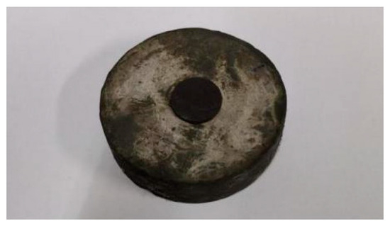
Figure 3.
Cementing diagram of cement sheath and core after curing 48 h.
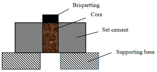
Figure 4.
Schematic diagram of experimental device.
2.3. Performance Test of Preflush Fluid System
The preflush fluid performance test mainly includes a prelude water loss test, settlement performance test, rheology test and interface cementation experiment. These experiments are described below.
- (1)
- Filtration property test
According to the API (American Petroleum Institute, Washington, D.C., USA) standard, the water loss of the mud shale cementation pre-liquid system at 35 °C and 6.9 MPa for 30 min was improved by using the water loss meter. The filtration performance of the pre-liquid system can be evaluated by the filtration rate.
- (2)
- Settlement performance test
The density of the antecedent liquid was measured by using a density scale. The upper, middle and lower slurries were extracted after 2 h of standing, and their densities were measured separately by density scale. The maximum density difference was calculated.
- (3)
- Rheological test
The rheological properties of the preflush fluid were tested using a six-speed rotational viscometer. The indications at different rotational speeds were recorded separately, and the power law model was chosen to be utilized for the analysis of its rheological properties.
3. Results and Discussion
3.1. Influence of the Coupling Agent on Cementation Strength at Different Temperatures
A silane coupling agent solution (mass concentration 0%, 0.1%, 0.2%, 0.3%, 0.4%, 0.5%), KH silane coupling agent solution (mass concentration 0%, 0.1%, 0.2%, 0.3%, 0.4%, 0.5%), and LD aluminium–zirconium coupling agent solution (mass concentration 0%, 0.1%, 0.2%, 0.3%, 0.4%, 0.5%) were configured. After 48 h of curing under 70 °C, 90 °C, and 150 °C, the cementation strength of the formation–cement ring interface is shown in Figure 5. After curing at different temperatures, the cementation strength of the three coupling agents increased. Under the same temperature, the cementation strength of the LD aluminium–zirconium class treated first increased and then stabilized with the increase in concentration, while the cementation strength of the KH and A silane class treated first increased and then decreased with the increase in concentration. Moreover, the interface enhancement effect was the best with the A silane coupling agent at 150 °C, and the optimal concentration of the A silane coupling agent was 0.3%.
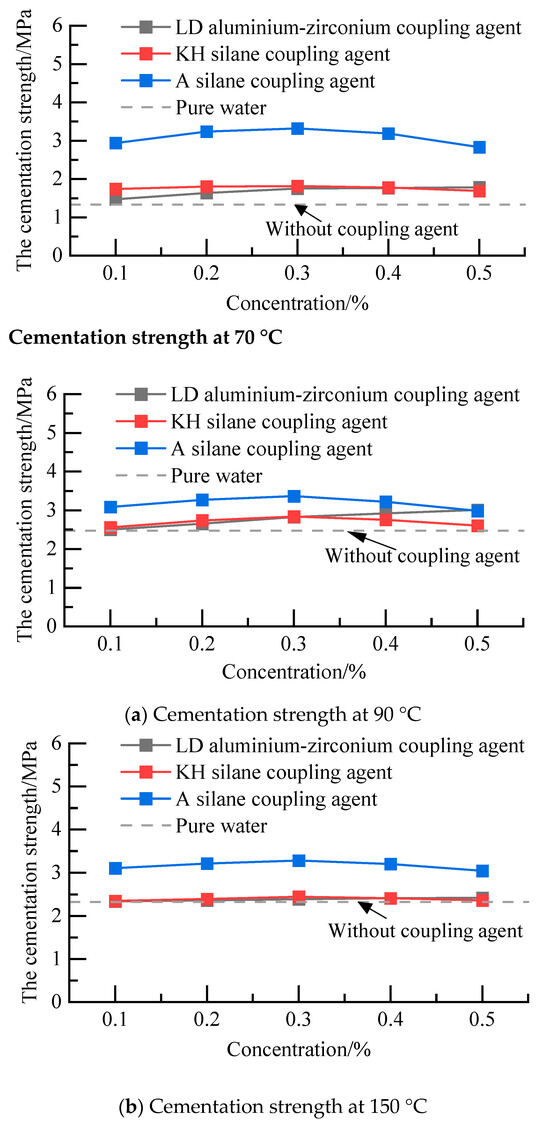
Figure 5.
Cementation strength of the formation–cement ring interface under different concentrations.
3.2. Effect of Compound Interface Enhancer on Improving Interface Cementation Strength
Among the three coupling agents with the best elevating effect, the A silane coupling agent and KH silane coupling agent were selected to compound. Through experiments, the effects of the mixing ratio, optimal concentration, and temperature change on the improvement of interface cementation strength were explored so as to obtain a compound coupling agent that can effectively improve the interface cementation strength.
The ratio of the A silane coupling agent and KH silane coupling agent was 1:1. The total concentrations of the A silane coupling agent and KH silane coupling agent were 0.3%, 0.4%, and 0.5%, respectively. After 48 h of curing under 70 °C, 90 °C, and 150 °C, the cementation strength at the formation–cement ring interface was shown in Figure 6. The improvement effect of the KH silane coupling agent and A silane coupling agent on the formation–cement ring interface was better than that of a single reagent. The maximum increase in cementing strength of the formation–cement ring interface by the coupling reagent was 189.22% at 70 °C, and the maximum increase in cementing strength of the formation–cement ring interface by the coupling reagent was 49.2% at 90 °C. The maximum lifting capacity could reach 45.2% at 150 °C.
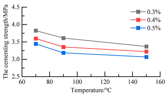
Figure 6.
Cementation strength of the formation–cement ring interface.
At the same concentration, with an increase in temperature, the cementation strength at the formation–cement ring interface decreased. The 0.3% A-KH silane coupling agent increased the cementation strength at the formation–cement ring interface the most. Therefore, the optimal mixing concentration is 0.3%.
3.3. Performance Evaluation of a Preflush Fluid System for Enhancing Shale Cementation
In this paper, a preflush fluid system for enhancing shale cementation was formed, and its composition is shown in Table 3. Slag was used as the weighting agent; xanthan gum was used as the suspension stabiliser; sulphonated phenolic resin was used as the filtration control agent. The interface enhancer was composed of 10% anhydrous ethanol mixed with 0.3% A–KH silane coupling agent (KH silane coupling agent and A silane coupling agent in a ratio of 1:1).
Table 3.
The preflush fluid system for enhancing shale cementation.
3.3.1. Filtration Property Test
A water loss apparatus was used to measure the fluid loss of the preflush fluid system at 35 °C and 6.9 MPa for 30 min so as to evaluate whether the filtration property was up to the API standard.
The measurement results showed that the fluid loss was 52 mL with 2% sulfonated phenolic resin. The preflush fluid has good filtration performance, and the filter cake formed was thinner and denser, as shown in Figure 7.
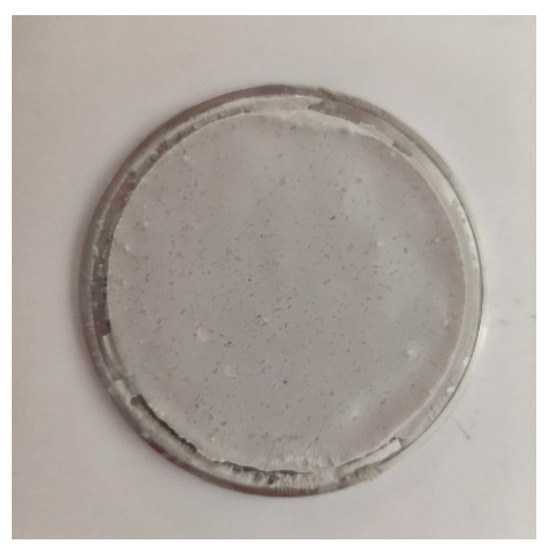
Figure 7.
Filter cake.
3.3.2. Settlement Performance Test
The density balance was used to measure the density of the preflush fluid. The upper, middle, and lower slurry were extracted after standing for 2 h. Subsequently, the maximum density difference was calculated. The experimental results are shown in Table 4 The results showed that the density of the preflush fluid system was 1.15 g·cm−3, and the maximum density difference was 0.02 g·cm−3 after standing for 2 h, which was up to the construction requirements (less than 0.05 g·cm−3).
Table 4.
Settlement performance of the preflush fluid system.
3.3.3. Rheological Test
Rheological tests were performed by a six-speed rotational viscometer. Rheological parameters were calculated using a power-law model to evaluate the rheological properties of the precursor fluid. As can be seen from Table 5, the rheological property of the preflush fluid system with the 0.1% xanthan gum was the best. However, as shown in Figure 8, the preflush fluid system with the 0.1% xanthan gum showed obvious stratification after standing for 2 h. Therefore, 0.2% xanthan gum was selected to ensure suspension stability. (n is the rheological index and K is the consistency factor. A larger n indicates better rheological properties.)
Table 5.
Rheological properties of the preflush fluid system with different xanthan gum dosage.
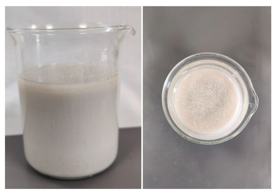
Figure 8.
Layering phenomenon of the preflush fluid.
3.3.4. Cementation Strength Test
In order to explore the impact of improving the preflush fluid system for shale cementation on the shale formation–cement ring interface cementation strength, the formation–cement ring interface cementation strength of cores treated with water, the interface enhancer, the conventional preflush fluid, and the improved shale cementation preflush fluid system were compared at 70 °C and 150 °C, respectively.
It can be seen from Table 6 that at 70 °C and 150 °C, compared with the pure water system, the conventional preflush fluid had little effect on the improvement of the interface cementation strength. The improvement effects of the improved shale cementation preflush fluid system and the interface enhancer were basically the same, indicating that other admixtures in the preflush fluid system could not affect the improvement effect of the interface enhancer.
Table 6.
The shale formation–cement ring interface cementation strength.
In the summary, a preflush fluid system for improving shale cementation was formed, which was composed of 30% slag, 10.3% interface enhancer, 0.2% xanthan gum and 2% sulfonated phenolic resin. Water was used as a dispersing medium.
4. Mechanism and Implication
4.1. Cement–Formation Interface Cementing Mechanism
The main ingredients in G-grade cements commonly used for cementing are calcium silicate and calcium aluminate, among others [25]. Silicate cement hydration process products are also more complex; the main components are C-S-H (hydrated calcium silicate), calcium alumina and Ca(OH)2 [26]. In the transition zone at the interface between the strata and the cement, the products of cement hydration are mainly calcium alumina and Ca(OH)2 crystals. With the deepening of the hydration reaction, the crystals in the transition zone of the interface were enlarged, and the C-S-H gel generation was suppressed, resulting in insufficient interfacial cementation strength [27].
A study has shown that siloxyl bonds are introduced at the interface to enhance the bonding energy of the C-S-H gel to the interface. The siloxys can generate C-S-H gels with Ca(OH)2 crystals, which can enhance the interfacial strength. Moreover, in this study, introducing siloxysilicon can improve the cementing interface’s cementing performance by using a nano-fluid silica cement slurry system [27].
4.2. Interface Enhancement Mechanisms
The coupling agent is a substance with two different functional groups. In many applications, it generally acts as a “molecular bridge” to improve the properties of the composite material and enhance the bonding strength between different substances [28]. The reaction mechanism of the silane coupling agent is illustrated as an example. The reaction of the coupling agent between the rock and cement can be divided into three stages: (1) hydrolysis and condensation of the coupling agent to produce Si-OH chemical bonds; (2) chemical bonding of the Si-OH chemical bonds with hydroxyl groups on the rock surface; and (3) chemical bonding of the coupling agent with hydroxyl groups in the cement slurry [29,30]. The process is shown in Figure 9. The reaction mechanism of aluminium–zirconate coupling agents is essentially similar.
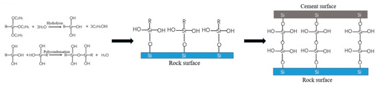
Figure 9.
Reaction mechanism of silane coupling agent.
The cementation between rock and cement is similar to the mechanism of the silane coupling agents. Both are bonded through the Si-O-Si structure. The coupling agent actually replaces the original cementing structure between the rock and cement to realize the cementing effect between the two. This enables good cementation in areas where the cementation is weak.
For the systems in which only one coupling agent acted, the Si-OH generated by the hydrolysis of aluminium–zirconium coupling agents and silane coupling agents could react with the hydroxyl groups on the rock surface to form hydrogen bonds. After dehydration, the silicon atoms in the coupling agent could form a Si-O-Si structure with the silicon atoms in the rock, resulting in cementation. Subsequently, the remaining Si-OH groups could react with other coupling agents or exist in free form. Then, the coupling agent reacted with the chemical bond of the cement slurry. After the cement slurry was injected around the rock, a large number of hydroxyl groups in the slurry reacted with the free Si-OH groups. With the hydration and solidification process of the cement slurry, dehydration and condensation formed a chemical bond, thus finally realizing the cementation of the coupling agent between the two inorganic materials of rock and cement slurry. There are studies that prove this [30,31]. Mechanistically, the coupling agent works by dehydrating and polycondensation with the hydroxyl groups of the rock and cement. Different coupling agents have different ability to hydrolyse hydroxyl groups. Therefore, the improvement effect of different coupling agents is different.
For the coupling agent compound action system, in addition to the reaction between the hydroxyl group in the coupling agent and the hydroxyl group in the cement to form cement, the free functional groups of the coupling agent could also react with the compound in the rock or cement, which formed a chemical bond. After the coupling agent compounding, the type and number of functional groups in the solution increased, which was more likely to react with the compound in the cement, Therefore, the bonding strength of the cementing interface was improved. In addition, the discontinuous distribution of hydrophobic groups on the rock surface prevented the formation of a continuous water film on the rock surface, and it prevented the formation of loose large crystals at the interface during the cement hydration process, resulting in a dense interface layer structure. Relevant studies have confirmed this through microscopic analyses [29]. It has also been suggested that modification with silane coupling agents can optimise the elemental distribution in the interface transition zone. Thus, in the later stages of cement hydration, the silane coupling agent enhances the densification of the hydration products in the interface transition zone [32,33]. This is in general agreement with the experimental results of this study, which explains why the coupling agent can enhance the cementing strength of the second interface.
5. Conclusions
- (1)
- The compound interface enhancer was formed, in which the ratio of the A silane coupling agent and KH silane coupling agent was 1:1. The total concentration of the A–KH silane coupling agent was 0.3%. The dosage of anhydrous ethanol was 10%, and water was used as dispersing medium. Interface enhancers significantly strengthen the cementing strength between the formation and the cement.
- (2)
- A preflush fluid system for improving the cementing strength between the shale and cement was formed, which was composed of 30% slag, 10.3% interface enhancer, 0.2% xanthan gum and 2% sulfonated phenolic resin. Water was used as the dispersing medium. The preflush fluid system had great settlement stability, rheological properties, and filtration properties. It can significantly improve the cementation strength of shale rock with the maximum increase of 189.10%.
- (3)
- In conjunction with this study and others, it has been found that silane coupling agents can improve the cementing properties of cement and other materials by means of chemical bonding. However, there may be certain negative effects. For example, the effect of interfacial enhancers on the properties of cementite itself and the longevity of the cementation properties need to be further investigated. Relevant processes and technologies also need to be further investigated.
Author Contributions
Methodology, S.G.; data curation, Z.C.; writing—original draft preparation, H.T.; writing—review and editing, H.L.; supervision, Y.B. All authors have read and agreed to the published version of the manuscript.
Funding
This research received no external funding.
Data Availability Statement
The data presented in this study are available in the article.
Conflicts of Interest
The authors declare no conflict of interest.
References
- Opedal, N.; Torsæter, M.; Vrålstad, T.; Cerasi, P. Potential Leakage Paths along Cement-formation Interfaces in Wellbores; Implications for CO2 Storage. Energy Procedia 2014, 51, 56–64. [Google Scholar] [CrossRef]
- Gong, Y.; Wu, G.; Wan, F.; Li, B. Preliminary analysis and experimental study on the problem of cementing two interfaces. Oil Drill. Process 1998, 6, 38–41+43–100. [Google Scholar] [CrossRef]
- Gu, J.; Gao, X.; Liu, H. Two-interface sealing system for oil and gas well cementing and its damage model. Nat. Gas Ind. 2006, 74–76+155. [Google Scholar]
- Yin, C. A mud cake curing agent for surface casing and technical casing cementing in shale gas wells. Xinjiang Oil Gas 2021, 17, 36–39+2–3. [Google Scholar]
- Song, J.; Chen, X.; Xu, M.; Wu, Y.; Wang, X. Analysis and countermeasures of difficulties in preventing and controlling annular band pressure in shale gas wells. Drill. Min. Process 2019, 42, 32–35+2. [Google Scholar]
- Zou, C.; Dong, D.; Wang, S.; Li, J.; Li, X.; Wang, Y.; Li, D.; Cheng, K. Mechanism of shale gas formation, geological characteristics and resource potential in China. Pet. Explor. Dev. 2010, 37, 641–653. [Google Scholar] [CrossRef]
- Jia, C.; Zheng, M.; Zhang, Y. Unconventional hydrocarbon resources in China and the prospect of exploration and development. Pet. Explor. Dev. 2012, 39, 139–146. [Google Scholar] [CrossRef]
- Luo, R.; Cha, M.; He, H.; Gao, C.; Qu, J. Characteristics of pore structure of Paleocene mud shale in Nanbao Depression. J. China Univ. Pet. (Nat. Sci. Ed.) 2016, 40, 23–33. [Google Scholar]
- Yuan, Y.; Fan, M.; Liu, W.; Li, S.; Wo, Y. Study on sealing mechanism of caprock. Pet. Exp. Geol. 2011, 33, 336–340+347. [Google Scholar]
- Hu, W.; Lu, X.; Fan, M.; Zhang, J.; Cao, J. Progress in the study of mud shale capping: Types, microporous characteristics and capping mechanism. Miner. Rock Geochem. Bull. 2019, 38, 885–896+869. [Google Scholar] [CrossRef]
- Huang, H.; Bu, Y.; Tian, H.; Wang, R. Experimental study on the cementation strength of MTC cementing fluid at the diaphragm interface. J. China Univ. Pet. (Nat. Sci. Ed.) 2006, 46–50. [Google Scholar]
- Huang, H. Research on the Theory and Application of MTC Technology; China University of Petroleum: Beijing, China, 2007. [Google Scholar]
- Li, Y.; Lu, H.; Xing, X.; Xie, C.; Li, L. A review of research on improving cementation quality at the second interface of cementation. West. Prospect. Eng. 2016, 28, 62–65. [Google Scholar]
- Xie, F.; Wang, C. Multi-silica drilling fluids for improving the cementation strength at the diaphragm interface. Drill. Technol. 2002, 85–88+7. [Google Scholar]
- Sun, L. Development of Interface Enhancer for Improving Cementing Quality; Northeast Petroleum University: Daqing, China, 2014. [Google Scholar]
- Zhang, J.; Wang, J.; Su, H.; Zhu, B.; Meng, Q. A cement interface enhancer and its action mechanism. Arab. J. Geosci. 2015, 8, 7869–7877. [Google Scholar] [CrossRef]
- Wang, J.; Li, X.; Zhang, J.; Zang, W. Methods and techniques for attenuating the effect of mud cake on the cementation quality of the diaphragm interface. Contemp. Chem. 2016, 45, 2229–2232. [Google Scholar] [CrossRef]
- He, J.; Gao, L.; Zhang, S.; Hou, B.; Feng, F. Cementing weak interface enhancers and their effects on drilling fluid performance. Chem. Eng. 2022, 36, 52–55. [Google Scholar] [CrossRef]
- Wang, D.; Chen, X.; Yang, C. Research and application of cementing technology for preventing gas flow in tight gas reservoirs. Complex Reserv. 2023, 16, 13–18. [Google Scholar] [CrossRef]
- Yao, Y.; Jiao, J.; Deng, T. High-density preplacement fluid cementing technology for shale gas wells in western Sichuan. Nat. Gas Explor. Dev. 2014, 37, 86–89+14. [Google Scholar]
- Lichinga, K.N.; Maagi, M.T.; Wang, Q.; Hao, H.; Gu, J. Experimental study on oil based mudcake removal and enhancement of shear bond strength at cement-formation interface. J. Pet. Sci. Eng. 2019, 176, 754–761. [Google Scholar] [CrossRef]
- Jiao, L.; Yao, K.; Li, C.; Mu, N.; Wang, F.; Zheng, Y. Influence of isolation fluid material for cementing on the quality of interface cementation. Drill. Process 2019, 42, 104–107+12. [Google Scholar]
- Wu, Z.; Yue, J.; Xing, X.; Fan, B. Research and application of a new type of anti-pollution cementing preflush fluid system. Petrochem. Appl. 2021, 40, 48–52. [Google Scholar]
- GB/T 19139-2012; Test Methods for Oil Well Cement. National Oil and Gas Standardization Technical Committee: Beijing, China, 2012.
- Zhou, G. Experimental Research on Sealing and Simulation Evaluation of Shallow Cemented Wells; China University of Petroleum: Beijing, China, 2018. [Google Scholar] [CrossRef]
- Liu, X. Effect of high-temperature synthetic hydrated calcium silicate on the hydration process of oil well cement. Drill. Complet. Fluids 2022, 39, 200–207. [Google Scholar]
- Lu, P.; Wang, M.; Zhai, Q. Microstructural analysis and strengthening method of hydration products at the “cement-rock” interface. Chem. Eng. Equip. 2023, 16–18. [Google Scholar] [CrossRef]
- Chen, H.; Xiang, S.; Weng, L.; Lv, B. Synthesis of borate coupling agents. Plast. Sci. Technol. 1996, 24, 23–26. [Google Scholar]
- Li, Y. Research on the Formation Mechanism of Granite/Silane Coupling Agent/Cement Paste Interface Layer; Shantou University: Shantou, China, 2006. [Google Scholar]
- Li, Y.; Lu, X.; Feng, Y.; Xiong, G. Formation mechanism of granite/silane coupling agent/cement paste interface layer. J. Mater. Res. 2007, 140–144. [Google Scholar]
- Li, Y.; Xiong, G.; Feng, Y. Influence of temperature and immersing period on splitting tensile strength of granite/silane coupling agent cement paste interface. Build. Tech. Dev. 2006, 33, 34. [Google Scholar]
- Tan, X.; Feng, A.; Zhao, H. Study on surface grafting modification of nanosilica by silane coupling agent. China Powder Technol. 2011, 17, 14–17. [Google Scholar]
- Zhao, Y.; Shen, G.; Miao, Y.; Dong, Z.; Huang, K. Research progress on the application of silane coupling agent in concrete. Appl. Chem. Eng. 2023, 52, 1496–1501. [Google Scholar] [CrossRef]
Disclaimer/Publisher’s Note: The statements, opinions and data contained in all publications are solely those of the individual author(s) and contributor(s) and not of MDPI and/or the editor(s). MDPI and/or the editor(s) disclaim responsibility for any injury to people or property resulting from any ideas, methods, instructions or products referred to in the content. |
© 2024 by the authors. Licensee MDPI, Basel, Switzerland. This article is an open access article distributed under the terms and conditions of the Creative Commons Attribution (CC BY) license (https://creativecommons.org/licenses/by/4.0/).