Article

Impact of Temperature on Cement Displacement Efficiency: Analysis of Velocity, Centralization, and Density Differences

1
The Second Drilling Company, Daqing Drilling Engineering Company, Daqing 163413, China
2
College of Petroleum Engineering, Northeast Petroleum University, Daqing 163318, China
*
Author to whom correspondence should be addressed.
Processes 2024, 12(12), 2923; https://doi.org/10.3390/pr12122923
Submission received: 18 November 2024 / Revised: 11 December 2024 / Accepted: 18 December 2024 / Published: 20 December 2024
(This article belongs to the Special Issue Modeling, Control, and Optimization of Drilling Techniques)

Abstract

:
This paper investigates the impact of temperature on the rheological behavior of cement slurry and drilling fluid and examines how various factors, such as displacement speed, casing centralization, and density difference, influence displacement efficiency during cementing operations. Using numerical simulations validated against experimental data, we explore how these factors interact under different temperature conditions. Results indicate that temperature changes significantly affect the flow characteristics, displacement interface stability, and overall displacement efficiency. Findings demonstrate that optimizing these parameters according to temperature conditions can significantly enhance cementing performance and reduce the risk of fluid channeling and instability.

1. Introduction

The development of the socio-economic landscape is inseparable from the support provided by energy resources, and global energy demand is expected to increase significantly in the future. Oil and gas wells, serving as vital conduits for extracting crude oil and natural gas, have long posed a central challenge in drilling engineering: how to establish these conduits with precision and high quality. With the continuous rise in demand for oil and gas, readily accessible reserves are being depleted at a rapid pace. Onshore oilfields have largely entered their late development stages, and most easily exploitable large oil and gas reservoirs have already been tapped. Consequently, current efforts are focused on the development of challenging reserves, such as thin oil reservoirs, fault-block reservoirs, low-permeability reservoirs, marginal reservoirs, and residual oil deposits. These unconventional and hard-to-recover reserves present unique technical and economic challenges, necessitating innovative approaches to extraction and recovery [1,2,3].
The expansion of oil and gas exploration and production into increasingly complex geologies has significantly increased the demands on cementing technology. The challenges posed by intricate reservoir properties and complex geological conditions have elevated the difficulty of cementing operations. This has, in turn, opened up new opportunities for research and innovation in cementing techniques and technologies. Developing efficient and reliable cementing methods is critical for ensuring well integrity, enhancing recovery, and meeting the growing energy demands of modern society [4,5].
Cementing operations play a crucial role in oil extraction, as their quality directly impacts subsequent operations, the progress of oil field development, and the enhancement of oil and gas well productivity [6,7,8]. The core requirements of the cementing process are maintaining wellbore stability, effective mud displacement, and ensuring a secure seal [9,10]. Therefore, it is essential to prioritize and strive to improve the displacement efficiency during cementing operations. The key to enhancing cementing efficiency lies in optimizing the displacement effect of the cement slurry over the drilling fluid to minimize residual drilling fluid in the annulus, thereby maximizing the coverage of the cement slurry [11].
During cementing, various factors such as wellbore geometry, fluid properties, construction techniques, and technical parameters significantly influence the flow behavior and displacement effectiveness [12,13]. With the continuous advancement of drilling technology, particularly when targeting deeper formations, the thermal conditions of the formations become increasingly challenging. Under these extreme conditions, the rheological properties of drilling fluids are significantly affected, which is critical to the success of cementing operations [14].
Terry conducted high-temperature and high-pressure rheological experiments on ester-based drilling fluids and proposed a predictive method for their rheology, using measurements from a rotational viscometer [15]. Recent studies, such as the work by Fakoya et al. in 2018, have also demonstrated that the apparent viscosity of oil-based drilling fluids changes markedly with increasing temperature, organic clay concentration, and oil–water ratio [16]. These findings led to the development of empirical models to describe these variations. Research by Politte and Sherif further examined the rheology of oil-based drilling fluids under different temperature and pressure conditions, revealing the trends in apparent viscosity, plastic viscosity, and yield point as temperature and pressure changed. Similarly, studies on water-based drilling fluids have shown that their rheological properties are highly temperature-sensitive [17,18]. These insights not only deepen our understanding of the mechanisms behind the rheological behavior of drilling fluids but also provide theoretical support and practical guidance for optimizing cementing operations [19,20,21]. The nonlinear characteristics of casing centralizers under axial thrust play a crucial role in ensuring effective casing centralization, directly impacting the stability and efficiency of cementing operations. Advanced modeling and improvement of articulated casing centralizers, along with the development of interaction analysis models between centralizers and borehole walls, provide critical insights for optimizing centralizer design and performance [22,23,24].
In cementing operations, the rheological properties of the cement slurry directly affect the flow state in the annular space, making it a critical factor in slurry formulation and safe execution [25,26,27,28]. A well-formulated cement slurry with favorable rheological properties can optimize displacement efficiency within the pumpable time frame, thus ensuring cementing quality [29,30,31]. Research has shown that the impact of temperature on the rheological properties of cement slurry follows distinct patterns across different temperature ranges, with various systems exhibiting diverse trends [32,33,34]. At lower temperatures, the rheological parameters remain relatively stable, while at higher temperatures, these parameters change more significantly, leading to a sharp decline in the rheological behavior of the cement slurry [35,36,37].
In recent years, many studies have investigated the rheological properties of drilling fluids and cement-based slurries. For example, Mohamed et al. reviewed the significance and complexities of drilling fluid rheology in geothermal drilling [11]; Wang et al. examined the rheological behavior of high-density water-based drilling fluids under high-temperature and high-pressure conditions [19]; Mohammed et al. focused on the rheological properties of cement-based grouts using different testing methods [30]; and Stryczek et al. analyzed the time-dependent rheological parameters of fresh cement slurries [5]. However, these studies primarily concentrated on fundamental rheological characteristics and lacked a systematic exploration of how temperature-dependent rheology influences displacement efficiency during cementing operations. Addressing this gap, our study investigates the temperature-dependent rheological behavior of drilling fluids and cement slurries and its impact on displacement efficiency, aiming to provide optimized parameters and guidance for cementing operations under complex thermal conditions.
Since the changes in the rheological properties of drilling fluids and cement slurry under different temperature conditions can affect displacement efficiency and, consequently, wellbore sealing and stability, understanding displacement efficiency at varying temperatures is essential for maintaining the integrity of the cement sheath. This paper will discuss the impact of various factors on displacement efficiency under different temperature conditions, based on the trends in the rheological properties of drilling fluids and cement slurry. The aim is to provide a theoretical foundation for optimizing cementing design and improving cementing quality.

2. Materials and Methods

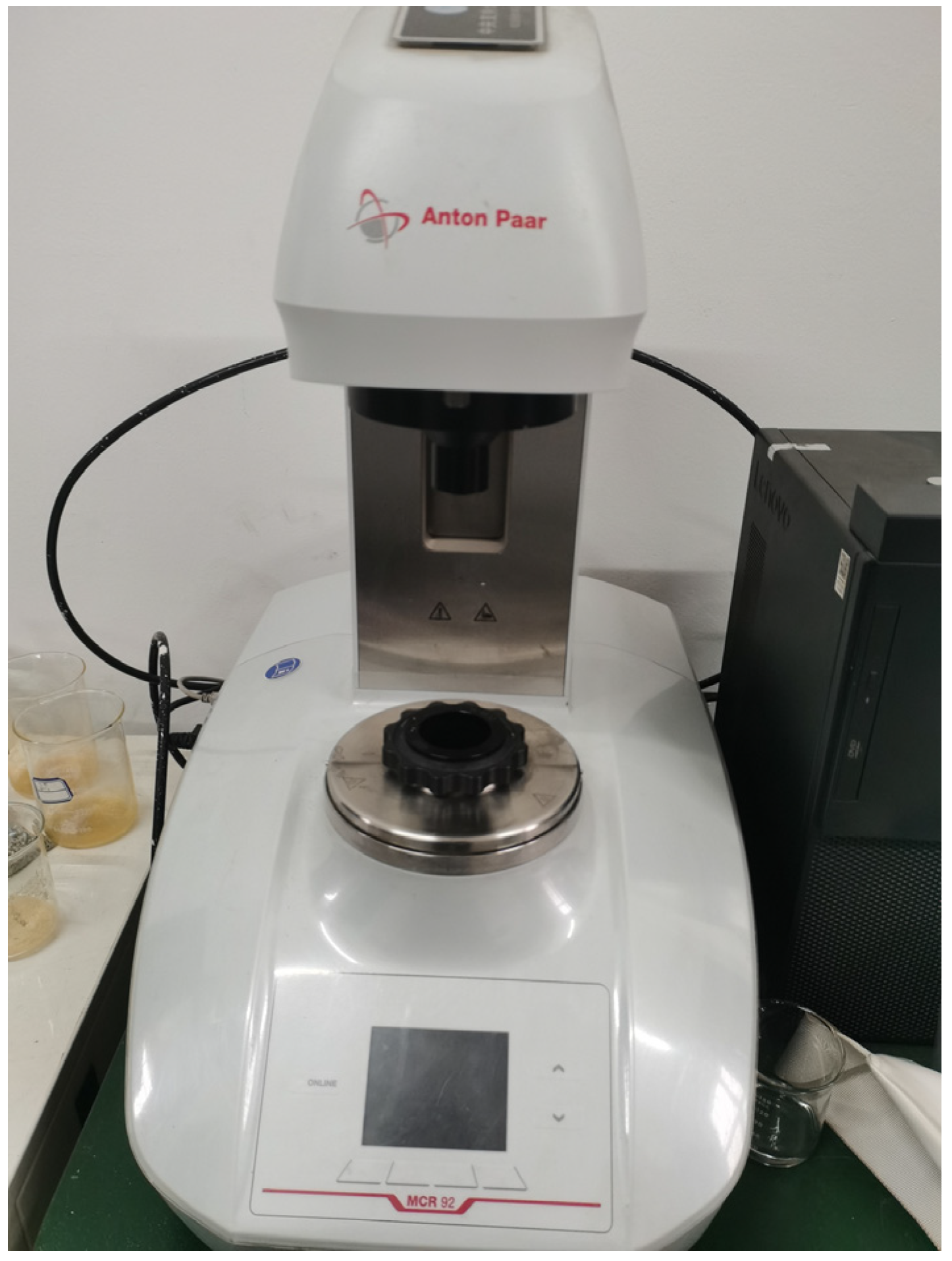
2.1. Rheology Measurement Experiment

The experiment was conducted using the Anton Paar MCR 92 advanced rheometer, which has a maximum operating temperature of 150 °C. The Anton Paar MCR 92 (Figure 1) rheometer is a high-precision, modular, and intelligent instrument designed for advanced rheological analysis. It features an air-bearing-supported synchronous EC motor, ensuring frictionless rotor movement for maximum sensitivity and accuracy. Its cutting-edge temperature control system combines air cooling with electrical heating, delivering precise thermal regulation. With a wide operational range, the rheometer supports rotational speeds from as low as 0.001 rpm to a maximum of 1500 rpm and provides a torque range up to 125 mNm. In rotational mode, it achieves a minimum torque of 1 μNm with an impressive resolution of 100 nNm. The rheological tests for the drilling fluid and cement slurry were performed at temperatures ranging from 20 °C to 120 °C. By measuring the viscosity of the fluids at various shear rates, the relationship between shear stress and shear rate at different temperatures was obtained, resulting in rheological curves. The results were then fitted to appropriate rheological models, such as Newtonian, power-law, and Herschel–Bulkley models, to evaluate the rheological properties.

2.1.1. Rheological Testing of Drilling Fluid at Different Temperatures

Rheological tests on the drilling fluid were conducted at six different temperatures: 20 °C, 40 °C, 60 °C, 80 °C, 100 °C, and 120 °C. During the experiment, fluid viscosity was measured at 15 points across shear rates ranging from 0 to 1200 s−1. Figure 2 presents the results of the rheological performance of the water-based drilling fluid at various temperatures. Overall, the effect of temperature on the relationship between shear rate and shear stress for the water-based drilling fluid was highly significant. Under constant conditions, for shear rates below 400 s−1, the shear stress at a given shear rate increased progressively as the test temperature rose. For shear rates greater than 400 s−1, the shear stress decreased as the temperature increased. At a shear rate of 1000 s−1, the shear stress values at 20 °C and 120 °C were 151.57 Pa and 192.4 Pa, respectively, showing a substantial difference of 40.83 Pa. The extension lines of the rheological curves for the water-based drilling fluid at different temperatures did not pass through the origin.
From Table 1, it can be observed that as the temperature gradually increases, the fit of the experimental rheological data of the drilling fluid under the Herschel–Bulkley rheological model slightly declines. The yield stress τ0 represents the minimum stress required to initiate flow; a higher τ0 indicates better particle suspension but increases pumping difficulty. The consistency coefficient K reflects the fluid’s viscosity; a higher K means a thicker fluid, affecting both pumpability and flow resistance. The flow behavior index n describes how the fluid responds to shear; if n, it indicates shear-thinning behavior, where viscosity decreases at higher shear rates, making pumping easier. However, the overall correlation coefficient remains very high, indicating a good fit. With rising temperature, the initial yield stress gradually increases, while the consistency coefficient decreases, suggesting improved fluidity of the drilling fluid. The flow behavior index remains almost unchanged, indicating that the deviation of the drilling fluid from Newtonian behavior is nearly constant.

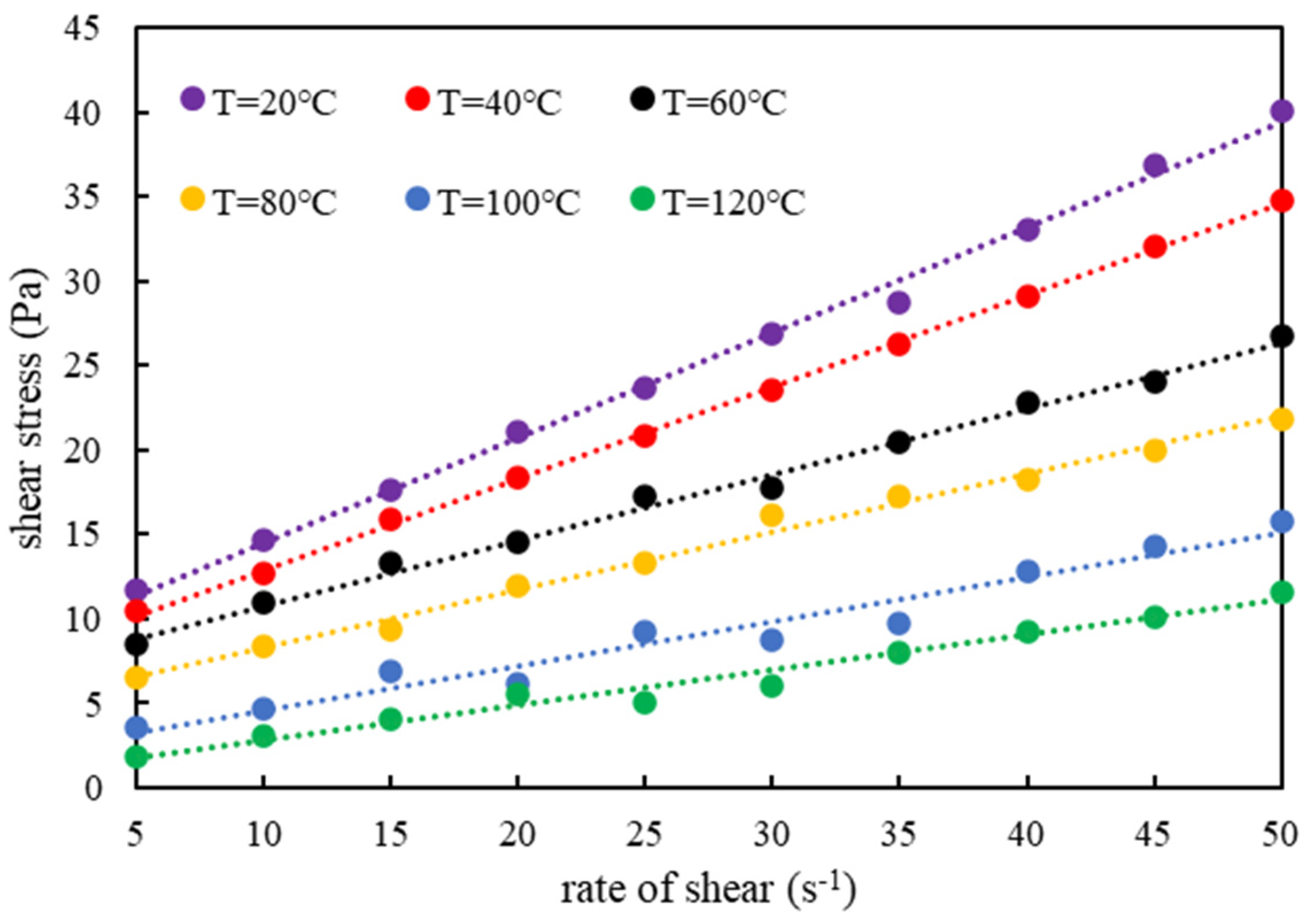
2.1.2. Rheological Testing of Cement Slurry at Different Temperatures

Rheological tests were conducted on cement slurry at six different temperatures: 20 °C, 40 °C, 60 °C, 80 °C, 100 °C, and 120 °C. Figure 3 shows the rheological performance test results for the water-based drilling fluid at different temperatures. The results indicate that as the temperature of the slurry increases, the minimum measured shear stress of the slurry progressively decreases. At a temperature of 120 °C, the minimum shear stress was the lowest at 1.85 Pa. When the slurry temperature reached 60 °C, the minimum shear stress was 8.52 Pa, which is 4.59 times that at 120 °C. At 20 °C, the minimum shear stress of the slurry was 11.75 Pa, which is 6.34 times that at 120 °C.
From Table 2, overall, when the temperature is below 80 °C, the correlation coefficient R2 for the linear fit of the relationship between slurry shear rate and shear stress is greater than 0.99. When the temperature exceeds 80 °C, the correlation coefficient R2 for the linear fit slightly decreases but remains above 0.95. The positive intercepts on the vertical axis indicate that the rheological behavior of the cement slurry conforms to the Bingham fluid model. In the Bingham fluid model, τ0 represents the yield stress, which is the minimum stress required to initiate flow, with higher values indicating more resistance to flow. μ is the plastic viscosity, representing the flow resistance once the yield stress has been exceeded; it defines the slope of the shear stress–shear rate curve and influences the ease of flow under shear.

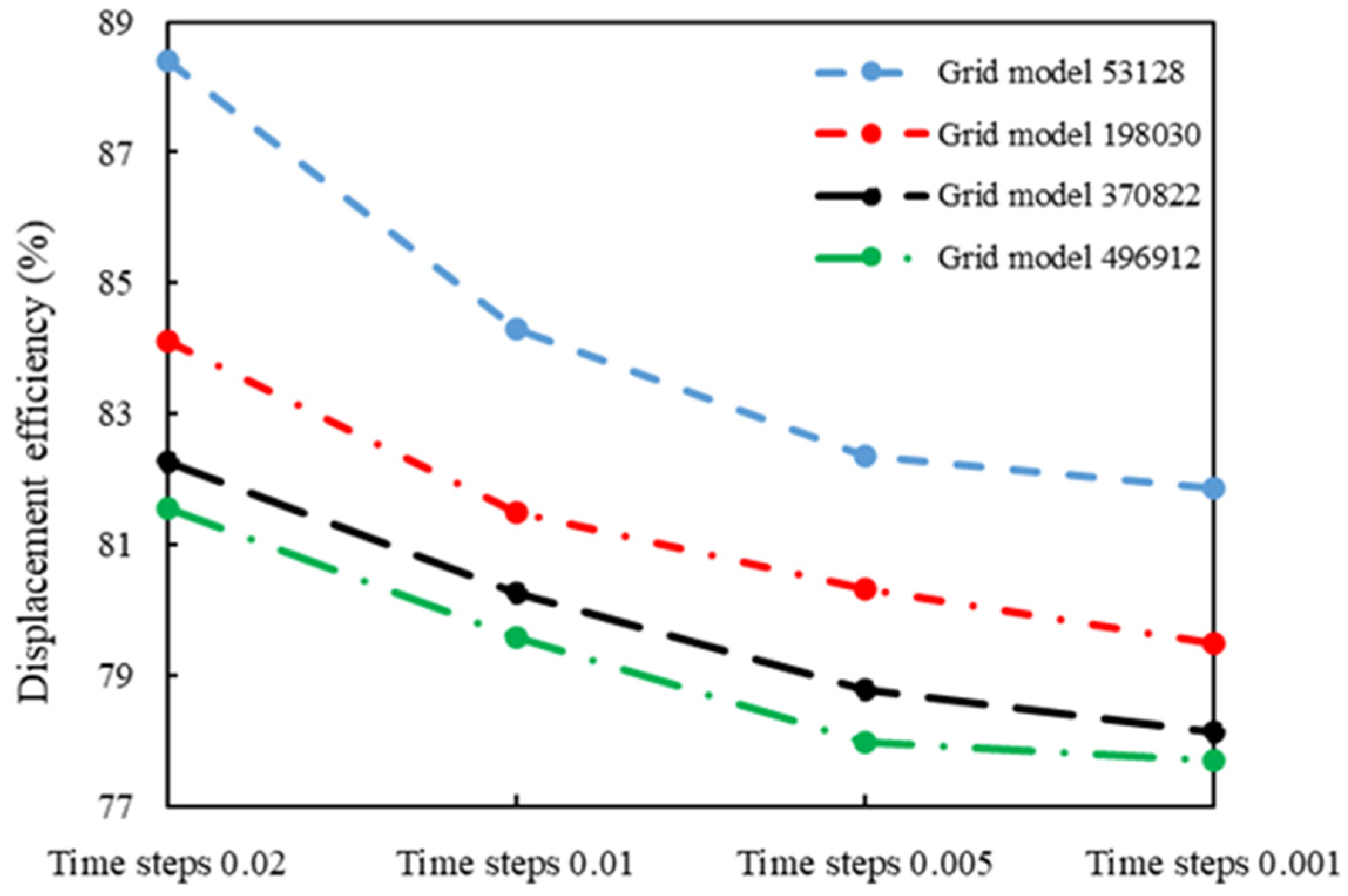
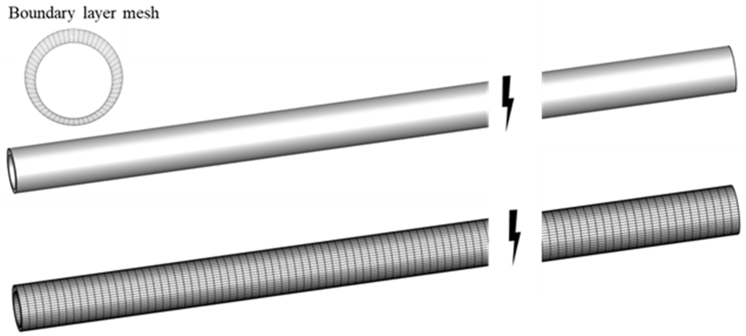
2.2. Geometric Model and Mesh Generation

A full-scale 3D annular geometric model of the horizontal well section was first established. The geometric dimensions of the wellbore annulus and the simulation parameters for cement slurry displacement flow are shown in Table 3.
Numerical simulation typically relies on discretization methods and numerical solution techniques. Mesh independence verification ensures consistency and convergence of numerical solutions under different mesh conditions. Verifying mesh independence and step size independence enhances the reliability and predictive capability of the numerical model. Increasing mesh density generally raises computational cost but improves the accuracy of the numerical solution. A refined mesh helps capture flow details and complex geometrical structures more accurately, especially when describing local phenomena such as boundary layers and vortices. Therefore, it is necessary to select an appropriate mesh density to balance computational cost and the accuracy of the numerical simulation results while maintaining computational efficiency. In this study, four different mesh sizes and four different time step sizes were selected for optimization.
From Figure 4, it can be seen that as the mesh density increases, the numerical simulation results tend to converge. When the time step was 0.01 and the number of mesh elements increased from 53,128 to 496,912, it was observed that under the mesh condition of 370,822, the variation trends of various flow field parameters became stable and consistent, indicating that the numerical simulation results had reached the standard of mesh independence. When the mesh number was 370,822, as the time step decreased, the displacement efficiency was reduced by 2%, 1.46%, and 0.66%, respectively. This suggests that the accuracy of the numerical simulation results improves as the time step decreases. Although a smaller time step can provide more accurate numerical solutions with better analytical capability and error control for flow field parameters, an appropriate time step must be chosen to balance computational time and resources. In this simulation, a time step of 0.005 was found to stabilize the variation trends of various flow field parameters, meeting the basic requirement for time step independence.
The boundary conditions for the simulation included a velocity inlet at the entry point, a pressure outlet at the exit, and a no-slip condition for the walls. To improve the convergence speed of the numerical simulation, the model was divided using a structured hexahedral mesh. A schematic diagram of the grid division is shown in Figure 5. A boundary layer mesh was set, and the height of the first layer of the annular radial mesh conformed to y+ ≈ 30, with a mesh growth rate of 1.2 [38]. The height of the first layer of the radial mesh was calculated using Equation (1).
y + = 0.172 Δ y D R e 0.9
In the equation: y+ represents the dimensionless distance from the first-layer mesh node to the wall; ∆y is the height of the first-layer mesh in millimeters (mm); Re is the Reynolds number of the cement slurry; and D is the hydraulic characteristic length of the annulus in millimeters (mm).

2.3. Numerical Simulation of Control Equations

During the simulation process, it was necessary to determine the flow regime of the cement slurry. The Reynolds number for a power-law fluid in the annulus can be calculated using the following equation, with a critical Reynolds number of 2100 [39].
R e = ρ ( D 1 D 0 ) v μ + τ 0 ( D 1 D 0 v )
In the equation, Re is the Reynolds number (dimensionless); ρ is the fluid density in kg/m3; D1 is the outer diameter of the annulus in meters (m); D0 is the inner diameter of the annulus in meters (m); μ is the plastic viscosity in Pa·s; τ0 is the yield stress in Pa; and v is the fluid velocity in m/s.
Cement slurry displacement flow is considered a two-phase flow and is simulated using the Volume of Fluid (VOF) model, which accurately describes the volume fraction of each component during the displacement process [40]. The governing equation is the volume fraction equation, mathematically expressed as follows:
α q t + v q α q = 0
In the equation, α is the volume fraction of the fluid (%), and ∇ is the Hamiltonian operator.
The hydrodynamic governing equations include the continuity equation and the momentum equation. Since turbulent displacement may occur in the cement slurry, the simulation should employ the k-ε turbulence model for such conditions [41]. The continuity and momentum equations are as follows:
t ( α q ρ ) + α q ρ v q = 0
( ρ v q ) + ρ v q v q = p + μ v q + v q T + ρ g + F
In these equations, P represents the pressure of the cement slurry in Pa; μ is the viscosity of the cement slurry in Pa·s; F is the exchange force between the cement slurry and drilling fluid in N; g is the gravitational acceleration in m/s2; and T denotes the matrix transpose symbol.
For simulations involving curved and rotating flow fields, the Realizable k-ε model provides more accurate results compared to the standard k-ε model [42]. The transport equations for turbulent kinetic energy and its dissipation rate in the Realizable k-ε model are as follows:
ρ k t + ρ k v q x j = x j μ + μ T σ k k x j + G ρ ε
( ρ ε ) t + ( ρ ε u j ) x j = x j ( μ + μ T σ ε ) ε x j + ρ C 1 S ε ρ C 2 ε 2 k + μ ρ ε
In these equations, k is the turbulent kinetic energy in m2/s2; ε is the dissipation rate in m2/s3; σk and σε are the Prandtl numbers, with σk = 1.0 and σε = 1.2; G is the generation of turbulence kinetic energy due to mean velocity gradients in Pa/s; uj is the mean velocity of the j phase in m/s; xj is the coordinate component in m; μT is the turbulent viscosity coefficient in Pa·s; S is the modulus of the mean strain rate tensor; and C1 and C2 are constants, where C1 = 1.44 and C2 = 1.90.

3. Results and Discussions

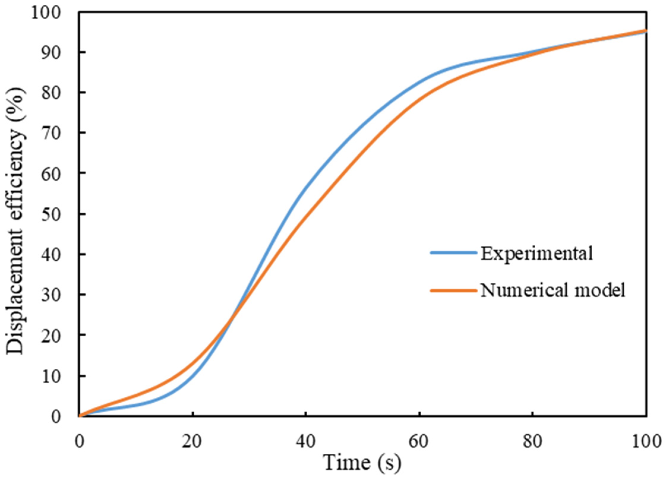
3.1. Model and Experimental Validation

Since numerical simulations are based on certain assumptions, mathematical models, and computational methods, it is necessary to validate the accuracy of the model. In this study, the numerical simulation results for displacement efficiency at different time points with a displacement rate of 12 L/s were compared with Xu’s experimental results [43]. The results are shown below. From Figure 6, it can be observed that the average error between the numerical simulation results and the experimental results is 9.07%. Therefore, the numerical simulation model is considered accurate and applicable, making it suitable for predicting actual engineering problems.
In order to simplify the complexity of the simulation and to improve the accuracy of the results, we have made the following assumptions about the simulation setup: the simulation conditions are medium- to high-temperature strata at temperatures up to 120 degrees Celsius; the simulation does not take into account the influence of thermal effects on the fluid properties; and the simulation does not take into account the influence of the formation of gas-phase or solid-phase inclusions.

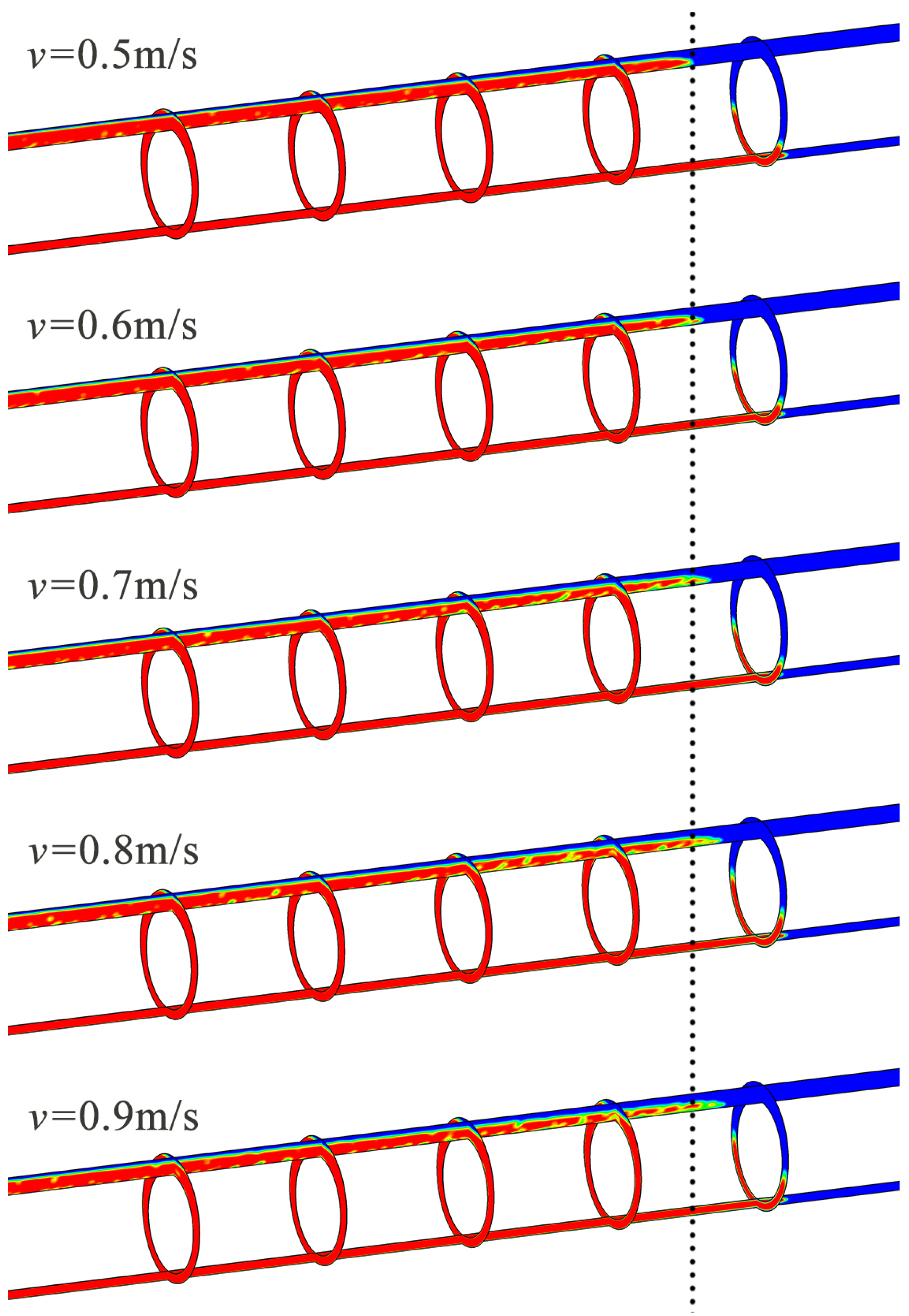
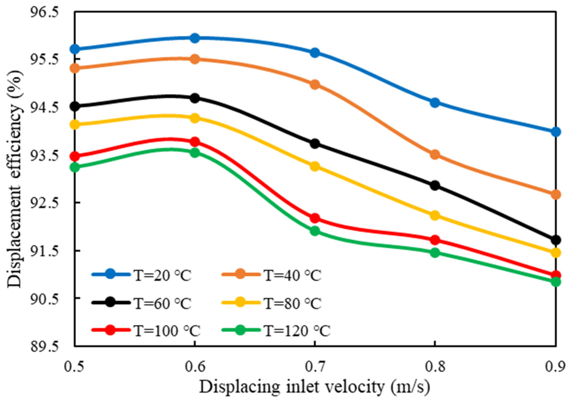
3.2. Displacement Inlet Velocity

In cementing field operations, the displacement velocity of the cement slurry must be controlled to avoid issues like particle settling due to gravity, which leads to stratification or premature thickening. While turbulent displacement can ensure higher displacement efficiency, excessive turbulence can destabilize the wellbore by exerting strong impacts. Additionally, turbulent displacement requires more advanced cementing equipment. Compared to plug flow and turbulent flow, laminar flow is widely studied and offers better control over displacement speed.
Using Equation (2), the calculated Reynolds numbers for cement slurry at velocities of 0.5 m/s and 0.6 m/s were less than 100, indicating plug flow as they fell below the laminar flow threshold. At velocities of 0.7 m/s, 0.8 m/s, and 0.9 m/s, the Reynolds numbers indicated laminar flow, as they did not exceed the turbulent threshold.
Figure 7 demonstrates that during displacement, the slurry advances more rapidly along the narrow side of the annulus compared to the wider side. This behavior is mainly due to the higher density of the cement slurry compared to the drilling fluid, causing the denser slurry to move downwards under gravity, accelerating the flow on the narrow side. Numerical simulations reveal that at lower displacement speeds, the cement slurry follows a plug flow pattern, with minimal mixing and clear trailing edges. As the speed increases, the flow transitions to laminar flow, introducing mixing at the displacement interface and making it less stable. At 0.8 m/s, the interface shows instability and irregularity, with mixing between the drilling fluid and cement slurry, which can lead to fluid retention and reduced displacement efficiency.
As the flow velocity increases further, the gravitational effect weakens, and fluid tends to advance more through the wider gaps, reducing the difference in displacement between narrow and wide gaps. This suggests that moderate increases in displacement velocity can enhance efficiency, but excessive velocity may cause mixing, undermining cementing effectiveness.
As can be seen in Figure 8, temperature is another critical factor affecting displacement efficiency. When the flow is laminar, the impact of temperature becomes more pronounced. For example, at a flow velocity of 0.7 m/s, increasing the temperature from 20 °C to 120 °C reduced the displacement efficiency from 95.64% to 92.41%, a 3.73% drop. At 0.9 m/s, the efficiency decreased from 93.98% to 90.85%, a reduction of 3.13%. On average, increasing the temperature from 20 °C to 120 °C lowered the efficiency by 2.43% for plug flow and by 3.33% for laminar flow. This heightened sensitivity in laminar flow is due to its greater responsiveness to changes in fluid rheology.
As the temperature rises, the yield stress of the drilling fluid increases, resulting in greater friction between the fluid, the wellbore, and the casing wall, which reduces displacement efficiency. Although the consistency coefficient of the drilling fluid decreases with increasing temperature, facilitating displacement, once temperatures exceed 100 °C, the yield stress and plastic viscosity of the cement slurry drop significantly. This reduction diminishes the slurry’s ability to displace the drilling fluid, increasing the likelihood of mixing and reducing efficiency. The largest efficiency decrease was observed when the temperature rose from 40 °C to 60 °C; at a flow velocity of 0.7 m/s, the efficiency dropped by 1.23%. This is because the consistency coefficient of the drilling fluid at these temperatures is higher than at 20 °C, emphasizing the need for optimizing high-temperature resistance properties of both the drilling fluid and cement slurry during displacement operations above 40 °C.

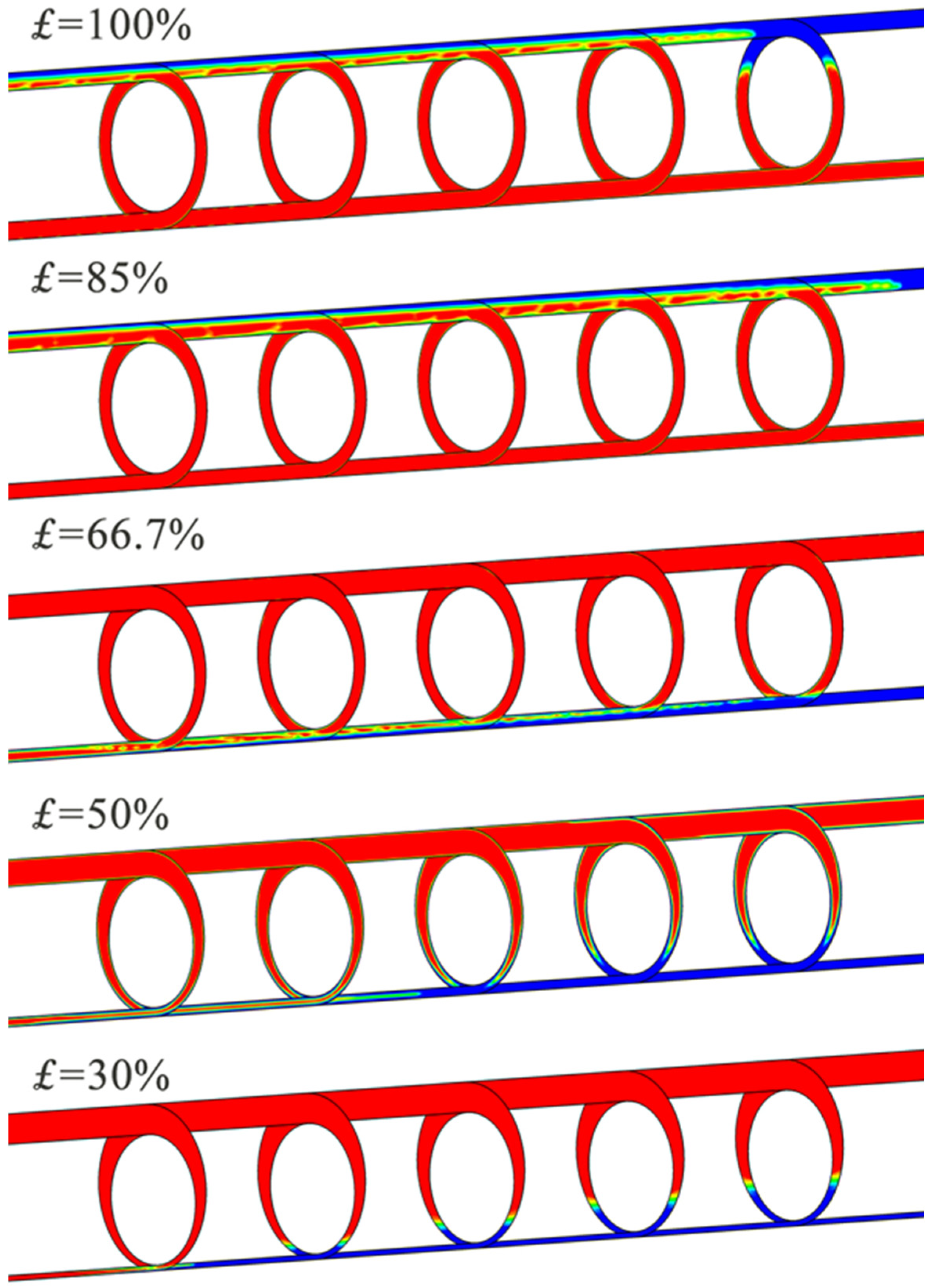
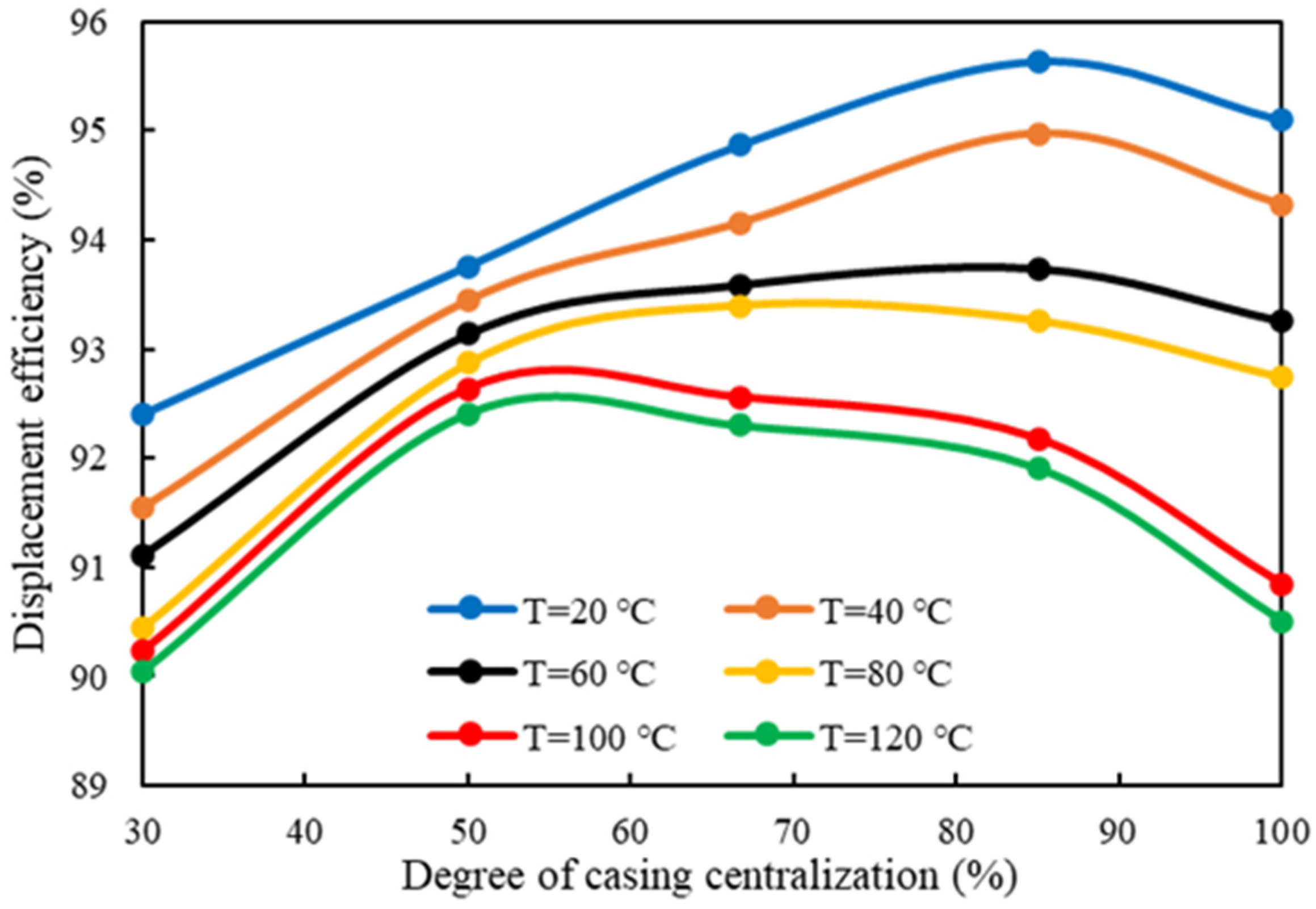
3.3. Degree of Casing Centralization

As the casing centralization decreases, the displacement efficiency exhibits a complex trend of initially increasing and then decreasing. This phenomenon is particularly important in the processes of oil and gas well drilling and cementing. Fluids moving at faster speeds are termed “fast flow”, whereas slower-moving fluids are referred to as “slow flow”. Analyzing the displacement interface helps clarify the reasons behind this trend.
When the casing is centered, the cement slurry, due to its positive density difference, is affected by buoyancy and gravity forces. Under these conditions, the cement slurry tends to displace more easily through the lower side of the annular space, causing the displacement interface to tilt and impacting fluid flow characteristics. As centralization decreases to 0.85, the presence of eccentricity leads to uneven resistance in different gaps, significantly influencing the axial and radial distribution of flow velocity. This resistance disparity not only counters the gravitational effect but also stabilizes the displacement interface, improving displacement efficiency.
As can be seen in Figure 9, when centralization further decreases to 0.5, the resistance differences induced by eccentricity become the dominant factor in the displacement process. At this point, the cement slurry more readily moves through the wider upper gap, while flow in the narrower lower gap is notably restricted, resulting in a pronounced slow flow phenomenon. When centralization reaches as low as 0.3, significant instability at the displacement interface is observed, with clear differences in displacement rates between the upper wide gap and lower narrow gap. The slow flow phenomenon becomes prominent, causing interface instability and reduced displacement efficiency. This indicates that in actual operations, controlling casing eccentricity is crucial for optimizing displacement efficiency.
Figure 10 shows that overall, displacement efficiency decreases with increasing temperature, and increases first and then decreases with greater casing centralization. At temperatures of 20 °C, 40 °C, and 60 °C, the optimal centralization is 85%, yielding displacement efficiencies of 95.64%, 94.97%, and 93.74%, respectively. When the temperature rises to 80 °C, the optimal centralization drops to 66.7%, with a displacement efficiency of 93.4%. As temperatures continue to rise to 100 °C and 120 °C, the optimal centralization falls further to 50%, with corresponding efficiencies of 92.64% and 92.41%.
With increasing temperature, the yield stress and viscosity of the cement slurry decrease. At 20 °C, 40 °C, and 60 °C, an 85% centralization results in resistance differences balancing the gravitational effect, optimizing displacement efficiency. However, as temperatures rise, the resistance difference at 85% centralization is insufficient to counteract the gravitational effect. When centralization is reduced further and temperature reaches 80 °C, the increased resistance difference at 66.7% centralization meets the necessary conditions for optimal efficiency. At 100 °C and 120 °C, where the yield stress and viscosity drop significantly, the highest displacement efficiency is achieved when centralization decreases to 50%.

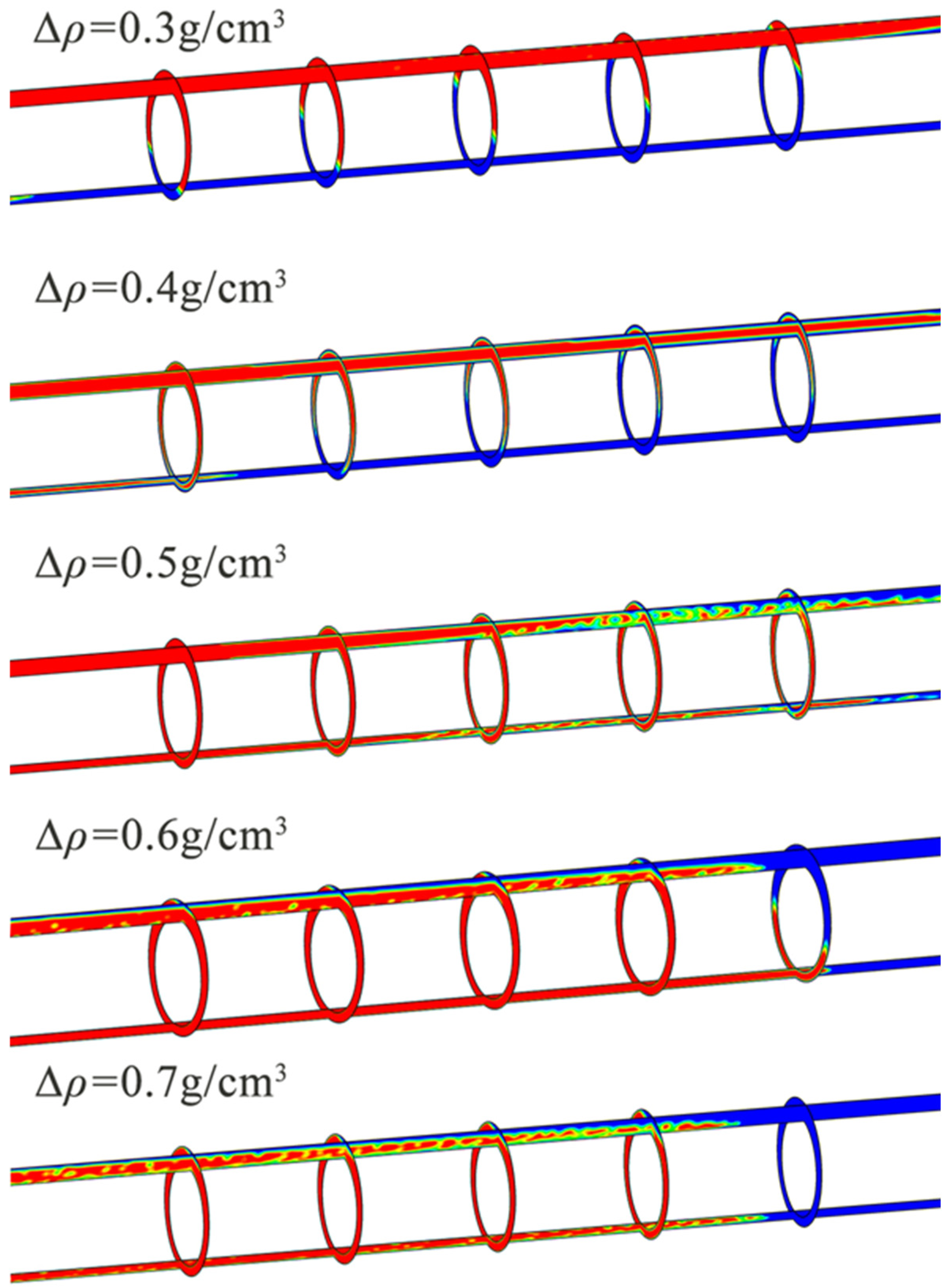
3.4. Density Difference

When the density of the drilling fluid remains constant, an increase in the density difference between the cement slurry and the drilling fluid results in a trend where displacement efficiency initially increases and then decreases. This indicates that density difference is a critical factor affecting displacement efficiency. Analyzing the displacement interface reveals that, under specific eccentric conditions, the casing may lean toward the borehole wall, leading to changes in flow behavior.
As can be seen in Figure 11, when the density difference is small, the buoyancy effect and the increased resistance in the narrow annular gap due to eccentricity cause the cement slurry to flow first into the wider upper section of the annulus. This flow restriction reduces the amount of cement slurry entering the narrow lower section, leading to uneven flow rates between the wider and narrower sections. Consequently, the cement slurry rapidly displaces the drilling fluid in the upper wide section, while a significant amount of undisturbed drilling fluid remains in the lower narrow section, creating potential for channeling and negatively affecting displacement efficiency. As the density difference increases, the pressure gradient driving the cement slurry rises. When the gravitational force of the cement slurry counteracts the negative impact of resistance due to casing eccentricity, the flow becomes more uniform, and the displacement interface smoothens, improving the overall displacement efficiency. Under conditions of 20 °C and constant drilling fluid density, a density difference in the range of 0.5 to 0.6 g/cm3 yielded the highest displacement efficiency, offering valuable guidance for optimizing displacement in horizontal wells.
Additionally, curves depicting displacement interface length as a function of density difference indicate high sensitivity of interface length to changes in density difference. An increase in density difference significantly shortens the displacement interface length, implying a more rapid and efficient displacement process. Conversely, as the density difference decreases, the sensitivity of the interface length increases, causing the length to rise more rapidly. This underscores the importance of carefully controlling density difference during design and construction.
In practical applications, increasing the density of the cement slurry within an appropriate range is vital for improving displacement efficiency. Adjusting the density helps enhance the flow characteristics of the displacement interface, reduce flow resistance, and boost overall operational efficiency.
Overall, as shown in Figure 12, displacement efficiency follows a trend of increasing and then decreasing with rising density difference. At 20 °C, the optimal density difference was 0.6 g/cm3, resulting in a displacement efficiency of 95.64%. When the temperature increased to 40 °C, the optimal density difference shifted to 0.5 g/cm3. This remained constant as the temperature increased to 80 °C, where the optimal displacement efficiencies were 95.05%, 94.12%, and 93.64% at 40 °C, 60 °C, and 80 °C, respectively. For temperatures of 100 °C and 120 °C, the optimal density difference was 0.4 g/cm3, yielding displacement efficiencies of 92.66% and 92.37%.
As temperature rises, molecular movement within the cement slurry accelerates, reducing intermolecular cohesive forces and leading to a decrease in shear stress and viscosity. An increased density difference enhances buoyancy, promoting the displacement of lighter fluids and improving efficiency. However, an excessive density difference may destabilize flow, causing turbulence and stratification, which in turn reduces efficiency. At 20 °C, the optimal density difference of 0.6 g/cm3, with relatively higher viscosity and shear stress, supports effective displacement. At 40 °C, 60 °C, and 80 °C, maintaining a density difference of 0.5 g/cm3 helps avoid flow instability, maintaining high efficiency despite the reduced viscosity and shear stress. At higher temperatures of 100 °C and 120 °C, where viscosity significantly drops and fluidity increases, reducing the density difference to 0.4 g/cm3 supports stable flow, preventing stratification and maintaining efficiency.
In conclusion, as temperature increases, the reduction in viscosity and shear stress enhances fluid flow but may compromise stability and control. Particularly at high density differences, this can lead to greater flow instability and stratification risk. Therefore, in high-temperature environments, reducing the density difference helps maintain flow stability and improve displacement efficiency.

4. Conclusions

The primary innovation of this study lies in the systematic analysis of temperature-dependent rheological properties and their influence on displacement efficiency, combining experimental measurements with numerical simulations. The results demonstrate that the optimal parameters for achieving high displacement efficiency—such as displacement speed and density difference—vary significantly with temperature. This underscores the necessity of incorporating temperature-dependent rheological behavior into cementing design. Compared to the existing literature, this study uniquely integrates both experimental and simulation approaches to provide actionable insights and detailed parameter recommendations for improving cementing efficiency under medium- to high-temperature conditions, offering a new theoretical basis and practical guidance for effective zonal isolation. This study evaluated the effects of temperature on the rheological behavior of cement slurry and drilling fluids and analyzed how displacement velocity, casing centralization, and density differences influence displacement efficiency under varying temperatures.
(1)
Temperature Effects on Rheology: The study confirms that temperature significantly affects the rheological properties of both cement slurry and drilling fluid. As temperature increases, reductions in shear stress and viscosity alter fluid behavior, impacting the displacement process.
(2)
Displacement Speed: Proper control of displacement speed is essential at varying temperatures. Increased speeds can enhance efficiency but may cause interface instability and fluid mixing, particularly at higher temperatures.
(3)
Casing Centralization: Optimal casing centralization is crucial for maintaining displacement efficiency. Results indicate that an intermediate level of centralization can counteract gravitational and resistance effects in the annulus, especially under non-ideal temperature conditions.
(4)
Density Difference: An optimal range of density difference between cement slurry and drilling fluid must be maintained. While a higher density difference can increase buoyancy and promote displacement, excessive differences may lead to instability and layering. For high-temperature environments, operators should consider reducing the density difference to avoid efficiency loss due to fluid instability.
(5)
Shortcomings and Prospects: In order to facilitate their use, the results need to be adjusted. This can be considered based on the field data research and analysis to derive the impact weight of each factor, according to the weight assigned to derive the optimization equation, through iterative calculations to derive the optimal values of cementing parameters under a given working condition in practice.

Author Contributions

Methodology, X.T.; Validation, J.Z.; Data curation, D.L.; Writing—original draft, G.J.; Writing—review & editing, X.S. All authors have read and agreed to the published version of the manuscript.

Funding

This research was funded by the Study on Flow Field Behavior and Rock Cuttings Transport in Well Annulus, grant number 2024Z2X00112.

Data Availability Statement

The original contributions presented in this study are included in the article. Further inquiries can be directed to the corresponding author.

Conflicts of Interest

Xiaowei Tang, Jian Zhang and Dewei Liu are employed by the Second Drilling Company, Daqing Drilling Engineering Company. The authors declare that this research was conducted in the absence of any commercial or financial relationships that could be construed as potential conflicts of interest.

References

  1. Epelle, E.I.; Gerogiorgis, D.I. A review of technological advances and open challenges for oil and gas drilling systems engineering. AIChE J. 2020, 66, e16842. [Google Scholar] [CrossRef]
  2. Wang, H.; Huang, H.; Bi, W.; Ji, G.; Zhou, B.; Zhuo, L. Deep and Ultra-Deep Oil and Gas Well Drilling Technologies: Progress and Prospect. Nat. Gas Ind. B 2022, 9, 141–157. [Google Scholar] [CrossRef]
  3. Wu, Z.; Chen, Z.; Zhao, Y.; Xue, Y.; Wang, C.; Xiong, C.; Chen, S. Theoretical and Experimental Study on Cementing Displacement Interface for Highly Deviated Wells. Energies 2023, 16, 733. [Google Scholar] [CrossRef]
  4. Zeng, B.; Zhou, X.; Cao, J.; Zhou, F.; Wang, Y.; Wang, Y.; Song, Y.; Hu, J.; Du, Y. A Casing Deformation Prediction Model Considering the Properties of Cement. Processes 2023, 11, 695. [Google Scholar] [CrossRef]
  5. Stryczek, S.; Wiśniowski, R.; Gonet, A.; Złotkowski, A. The Influence of Time of Rheological Parameters of Fresh Cement Slurries. AGH Drill. Oil Gas 2014, 31, 123–133. [Google Scholar] [CrossRef]
  6. Lund, B.; Ytrehus, J.D.; Taghipour, A.; Divyankar, S.; Saasen, A. Fluid-Fluid Displacement for Primary Cementing in Deviated Washout Sections. In Proceedings of the ASME 2018 37th International Conference on Offshore Mechanics and Arctic Engineering, Madrid, Spain, 17–22 June 2018; Volume 8, pp. 1–9. [Google Scholar] [CrossRef]
  7. Renteria, A.; Sarmadi, P.; Frigaard, I. Cementing Irregular Horizontal Wellbores. In Proceedings of the ASME 2021 40th International Conference on Ocean, Offshore and Arctic Engineering, Online, 21–30 June 2021; Volume 10, pp. 1–10. [Google Scholar] [CrossRef]
  8. Wang, J.; Xiong, Y.; Lu, Z.; Zhang, W.; Wu, J.; Wei, R.; Li, X. Research on Key Technologies to Improve Cementing Displacement Efficiency. ACS Omega 2022, 7, 37039–37049. [Google Scholar] [CrossRef]
  9. McLean, R.H.; Manry, C.W.; Whitaker, W.W. Displacement Mechanics in Primary Cementing. J. Pet. Technol. 1967, 19, 251–260. [Google Scholar] [CrossRef]
  10. Zulqarnain, M.; Tyagi, M. Development of Simulations Based Correlations to Predict the Cement Volume Fraction in Annular Geometries after Fluid Displacements during Primary Cementing. J. Pet. Sci. Eng. 2016, 145, 1–10. [Google Scholar] [CrossRef]
  11. Mohamed, A.; Salehi, S.; Ahmed, R. Significance and Complications of Drilling Fluid Rheology in Geothermal Drilling: A Review. Geothermics 2021, 93, 102066. [Google Scholar] [CrossRef]
  12. Bu, Y.; Tian, L.; Li, Z.; Zhang, R.; Wang, C.; Yang, X. Effect of Casing Rotation on Displacement Efficiency of Cement Slurry in Highly Deviated Wells. J. Nat. Gas Sci. Eng. 2018, 52, 317–324. [Google Scholar] [CrossRef]
  13. Kiran, R.; Teodoriu, C.; Dadmohammadi, Y.; Nygaard, R.; Wood, D.; Mokhtari, M.; Salehi, S. Identification and Evaluation of Well Integrity and Causes of Failure of Well Integrity Barriers (A Review). J. Nat. Gas Sci. Eng. 2017, 45, 511–526. [Google Scholar] [CrossRef]
  14. Sun, B.; Wang, X.; Wang, Z.; Gao, Y. Transient Temperature Calculation Method for Deep-Water Cementing Based on Hydration Kinetics Model. Appl. Therm. Eng. 2018, 129, 1426–1434. [Google Scholar] [CrossRef]
  15. Hemphill, T. Prediction of Rheological Behavior of Ester-Based Drilling Fluids under Downhole Conditions. In Proceedings of the SPE International Oil Conference and Exhibition in Mexico, Villahermosa, Mexico, 5–7 March 1996; pp. 243–253. [Google Scholar] [CrossRef]
  16. Fakoya, M.F.; Ahmed, R.M. A Generalized Model for Apparent Viscosity of Oil-Based Muds. J. Pet. Sci. Eng. 2018, 165, 777–785. [Google Scholar] [CrossRef]
  17. Politte, M.D. Invert Oil Mud Rheology As a Function of Temperature and Pressure. In Proceedings of the SPE/IADC Drilling Conference, New Orleans, LA, USA, 6–8 March 1985; pp. 305–322. [Google Scholar] [CrossRef]
  18. Sherif, T.; Ahmed, R.; Shah, S.; Amani, M. Rheological Behavior of Oil-Based Drilling Foams. J. Nat. Gas Sci. Eng. 2015, 26, 873–882. [Google Scholar] [CrossRef]
  19. Wang, F.; Tan, X.; Wang, R.; Sun, M.; Wang, L.; Liu, J. High Temperature and High Pressure Rheological Properties of High-Density Water-Based Drilling Fluids for Deep Wells. Pet. Sci. 2012, 9, 354–362. [Google Scholar] [CrossRef]
  20. Wang, R.; Wang, Y.; Tyagi, M.; Chen, Y.; Kam, S.I. Multi-Dimensional CFD Analysis for the Prediction of Transient Wellbore Circulating Temperature Profile to Guide Offshore Cementing Job. J. Korean Soc. Miner. Energy Resour. Eng. 2019, 56, 344–358. [Google Scholar] [CrossRef]
  21. Yuan, B.; Yang, S.; Xu, B.; Zeng, S.; Li, P. Novel Evaluation Method for Flushing Efficiency Based on the Principle of Wall Shear Rate Equality under High Temperature and High Pressure. ACS Omega 2022, 7, 38796–38810. [Google Scholar] [CrossRef]
  22. Shatskyi, I.; Velychkovych, A.; Vytvytskyi, I.; Senyushkovych, M. Modeling of Nonlinear Properties of Casing Centralizers Equipped with Axial Thrust. In IOP Conference Series: Materials Science and Engineering, Proceedings of the 11th International Conference on Advanced Manufacturing Technologies (ICAMaT 2020), Bucharest, Romania, 29–30 October 2020; IOP Publishing: Bristol, UK, 2021; Volume 1018, p. 012003. [Google Scholar] [CrossRef]
  23. Shatskyi, I.; Vytvytskyi, I.; Senyushkovych, M.; Velychkovych, A. Modelling and Improvement of the Design of Hinged Centralizer for Casing. In IOP Conference Series: Materials Science and Engineering, Proceedings of the Innovative Manufacturing Engineering and Energy (IManEE 2019)—“50 Years of Higher Technical Education at the University of Pitesti”—The 23rd Edition of IManEE 2019 International Conference, Pitesti, Romania, 22–24 May 2019; IOP Publishing: Bristol, UK, 2019; Volume 564, p. 012073. [Google Scholar] [CrossRef]
  24. Shatskyi, I.; Velychkovych, A.; Vytvytskyi, I.; Seniushkovych, M. Analytical Models of Contact Interaction of Casing Centralizers with Well Wall. Eng. Solid Mech. 2019, 7, 355–366. [Google Scholar] [CrossRef]
  25. Hazra, A.; Raigar, R.K.; Lal, K.; Negi, H.S.; Kumar, P. Importance of Controlling Fluid Loss & Settling Behaviour of Weighted Spacers in HPHT Conditions. In Proceedings of the 2nd Indian Oil & Gas Chemistry, Chemicals & Additives Conference & Exhibition (IOGCA 2019), Ahmedabad, India, 16–17 September 2019; pp. 1–12. [Google Scholar]
  26. Lichinga, K.N.; Maagi, M.T.; Wang, Q.; Hao, H.; Gu, J. Experimental Study on Oil Based Mudcake Removal and Enhancement of Shear Bond Strength at Cement-Formation Interface. J. Pet. Sci. Eng. 2019, 176, 754–761. [Google Scholar] [CrossRef]
  27. Ikpeka, P.; Benedict, U.; Utojiuba, D.; Odo, J.; Uzuegbu, G. Effects of Additive Concentrations on Cement Rheology at Differenttemperature Conditions. In Proceedings of the SPE Nigeria Annual International Conference and Exhibition, Virtual, 11–13 August 2020. [Google Scholar] [CrossRef]
  28. Memon, K.R.; Shuker, M.T.; Tunio, S.Q.; Lashari, A.A.; Abbass, G. Investigating Rheological Properties of High Performance Cement System for Oil Wells. Res. J. Appl. Sci. Eng. Technol. 2013, 6, 3865–3870. [Google Scholar] [CrossRef]
  29. Gao, H.; Ai, Z.; Zhang, J.; Zhou, B.; Chen, F.; Wang, W.; Liu, Z.; Deng, Q.; Shi, Y.; Wang, Z. Numerical Simulation of Improving Cementing Displacement Efficiency under Narrow Safety Density Window. In Proceedings of the SPE/IATMI Asia Pacific Oil & Gas Conference and Exhibition, Bali, Indonesia, 29–31 October 2019. [Google Scholar] [CrossRef]
  30. Mohammed, M.H.; Pusch, R.; Knutsson, S.; Hellström, G. Rheological Properties of Cement-Based Grouts Determined by Different Techniques. Engineering 2014, 6, 217–229. [Google Scholar] [CrossRef]
  31. Pernites, R.; Padilla, F.; Clark, J.; Gonzalez, A.; Fu, D. Novel and High Performing Wellbore Cleaning Fluids with Surprisingly Flat Viscosity over Time and Different Temperatures. In Proceedings of the SPE Western Regional Meeting, Garden Grove, CA, USA, 22–26 April 2018. [Google Scholar] [CrossRef]
  32. Durmaz, S.; Karbasforoushan, H.; Ozbayoglu, E.M.; Miska, S.Z.; Yu, M.; Takach, N. Mixing of Cement Slurries during Cement Plug Setting. In Proceedings of the SPE Deepwater Drilling and Completions Conference, Galveston, TX, USA, 14–15 September 2016. [Google Scholar] [CrossRef]
  33. Funkhouser, G.P.; Leotaud, L.; Bratcher, J. Delayed-Release Suspending Aid Provides Cement-Slurry Stability in High-Temperature, Horizontal Wells. In Proceedings of the SPE International Symposium on Oilfield Chemistry, The Woodlands, TX, USA, 9–10 April 2015; Volume 1, pp. 221–230. [Google Scholar] [CrossRef]
  34. Shadravan, A.; Narvaez, G.; Alegria, A.; Carman, P.; Perez, C.; Erger, R. Engineering the Mud-Spacer-Cement Rheological Hierarchy Improves Wellbore Integrity. In Proceedings of the SPE E&P Health, Safety, Security and Environmental Conference-Americas, Denver, CO, USA, 16–18 March 2015; pp. 374–387. [Google Scholar] [CrossRef]
  35. An, J.; Li, J.; Huang, H.; Liu, G.; Yang, H.; Zhang, G.; Li, W. Mud Loss Behavior in Fractured Formation with High Temperature and Pressure. Energy Rep. 2023, 9, 2638–2652. [Google Scholar] [CrossRef]
  36. Wu, Y.; Salehi, S.; Khalifeh, M. Characterization of the Mud Displacement in an Enlarged Wellbore: An Integrated Rock-Fluid Model. J. Nat. Gas Sci. Eng. 2022, 100, 104471. [Google Scholar] [CrossRef]
  37. Renteria, A.; Sarmadi, P.; Thompson, C.; Frigaard, I.A. Effects of Wellbore Irregularity on Primary Cementing of Horizontal Wells, Part 1: Large Scale Effects. J. Pet. Sci. Eng. 2022, 208, 109581. [Google Scholar] [CrossRef]
  38. Balogh, M.; Parente, A.; Benocci, C. RANS Simulation of ABL Flow over Complex Terrains Applying an Enhanced K-ε Model and Wall Function Formulation: Implementation and Comparison for Fluent and OpenFOAM. J. Wind Eng. Ind. Aerodyn. 2012, 104–106, 360–368. [Google Scholar] [CrossRef]
  39. Vefring, E.H.; Bjorkevoll, K.S.; Hansen, S.A.; Sterri, N.; Saevareid, O.; Aas, B.; Merlo, A. Optimization of displacement efficiency during primary cementing. In Proceedings of the Latin American and Caribbean Petroleum Engineering Conference, Rio de Janeiro, Brazil, 30 August–3 September 1997. [Google Scholar] [CrossRef]
  40. Foroushan, H.K.; Ozbayoglu, E.; Gomes, P.J.; Miska, S.; Yu, M. Mud-Cement Displacement in Eccentric Annuli: Analytical Solution, Instability Analysis, and Computational Fluid Dynamics Simulations. In Proceedings of the IADC/SPE Drilling Conference and Exhibition, Fort Worth, TX, USA, 6–8 March 2018. [Google Scholar] [CrossRef]
  41. Foroushan, H.K.; Lund, B.; Ytrehus, J.D.; Saasen, A. Cement Placement: An Overview of Fluid Displacement Techniques and Modelling. Energies 2021, 14, 573. [Google Scholar] [CrossRef]
  42. Nasiri Khalaji, M.; Koca, A.; Kotcioğlu, İ. Investigation of Numerical Analysis Velocity Contours K-ε Model of RNG, Standard and Realizable Turbulence for Different Geometries. Int. J. Innov. Res. Rev. 2019, 3, 29–34. [Google Scholar]
  43. Xu, B.; Zhou, S.; He, F.; Wang, F.; Guo, J. Using Particle Image Velocimetry to Evaluate the Displacement Efficiency of Drilling Mud in Horizontal Well Cementing. J. Pet. Sci. Eng. 2020, 195, 107647. [Google Scholar] [CrossRef]
Figure 1. Anto Paar MCR 92 Advanced Rheometer.
Processes 12 02923 g001
Figure 2. Rheological Performance of Water-Based Drilling Fluid at Different Temperatures.
Processes 12 02923 g002
Figure 3. Rheological Performance of Cement Slurry at Different Temperatures.
Processes 12 02923 g003
Figure 4. Optimal Curve of Grid Number and Time Step.
Processes 12 02923 g004
Figure 5. Model diagram and grid division diagram.
Processes 12 02923 g005
Figure 6. Validation of Numerical Simulation Results with Experimental Data.
Processes 12 02923 g006
Figure 7. Cementing Displacement Efficiency Contour Plots at Different Speeds at 20 °C.
Processes 12 02923 g007
Figure 8. Relationship between Displacement Speed and Cementing Displacement Efficiency at Different Temperatures.
Processes 12 02923 g008
Figure 9. Cementing Displacement Efficiency Contour Plots at Different Casing Centralization Levels at 20 °C.
Processes 12 02923 g009
Figure 10. Relationship between Casing Centralization and Cementing Displacement Efficiency at Different Temperatures.
Processes 12 02923 g010
Figure 11. Cementing Displacement Efficiency Contour Plots at Different Density Differences at 20 °C.
Processes 12 02923 g011
Figure 12. Relationship between Density Difference and Cementing Displacement Efficiency at Different Temperatures.
Processes 12 02923 g012
Table 1. Fitting Results of Drilling Fluid Rheological Data under Herschel–Bulkley Model at Different Temperatures.
Temperature/°Cτ0/PaStandard ErrorK/Pa∙snStandard Errorn
206.4100.0880.4970.0050.858
4014.0111.1090.4190.0600.870
6020.1861.7590.4300.1050.851
8029.3761.5330.3720.0920.851
10035.2191.6360.3400.0980.850
12040.0581.8890.2510.0930.886
Table 2. Fitting Results of Cement Slurry Rheological Data under Bingham Plastic Model at Different Temperatures.
Temperature/°Cτ0/PaStandard Errorμ/Pa∙sStandard ErrorR2
208.3420.4190.6220.0140.995
407.4700.1570.5430.0050.999
606.9260.3310.3890.0110.993
804.8850.3210.3420.0100.992
1001.9500.6170.2630.0200.951
1200.7370.3750.2080.0120.970
Table 3. Geometrical Parameters and Operating Conditions in the Numerical Simulation.
VariablesValues
Annulus Length, L (m)10
Casing Pipe diameter, D0 (mm)244.5
Hole diameter, D1 (mm)311.1
Angle of inclination, θ1 (deg)90
Displacing inlet velocity, v (m/s)0.5, 0.6, 0.7, 0.8, 0.9
Degree of casing centralization, £ (%)30, 50, 66.7, 85, 100
Density difference, ∆ρ (g/cm3)0.3, 0.4, 0.5, 0.6, 0.7
Disclaimer/Publisher’s Note: The statements, opinions and data contained in all publications are solely those of the individual author(s) and contributor(s) and not of MDPI and/or the editor(s). MDPI and/or the editor(s) disclaim responsibility for any injury to people or property resulting from any ideas, methods, instructions or products referred to in the content.

