Article

Steam-Alternating CO2/Viscosity Reducer Huff and Puff for Improving Heavy Oil Recovery: A Case of Multi-Stage Series Sandpack Model with Expanded Sizes

1
School of Petroleum and Natural Gas, Changzhou University, Changzhou 213164, China
2
School of Petrochemical Engineering, Changzhou University, Changzhou 213164, China
3
Petroleum Exploration and Production Research Institute, Sinopec, Beijing 100083, China
*
Authors to whom correspondence should be addressed.
Processes 2024, 12(12), 2920; https://doi.org/10.3390/pr12122920
Submission received: 2 December 2024 / Revised: 16 December 2024 / Accepted: 18 December 2024 / Published: 20 December 2024
(This article belongs to the Section Energy Systems)

Abstract

:
Aiming at the challenges of rapid heat dissipation, limited swept efficiency, and a rapid water cut increase in steam huff and puff development in heavy oil reservoirs, an alternating steam and CO2/viscosity reducer huff and puff method for IOR was proposed. In this work, the effect of CO2 on the physical properties of heavy oil was evaluated, and the optimal concentration of viscosity reducer for synergistic interaction between CO2 and the viscosity reducer was determined. Next, novel huff and puff simulation experiments by three sandpack models of different sizes in series were analyzed. Then, the IOR difference between the pure steam huff and puff experiments and the steam-alternating CO2/viscosity reducer huff and puff were compared. Finally, the CO2 storage rate was obtained based on the principle of the conservation of matter. The results show that the optimal viscosity reducer concentration, 0.8 wt%, can achieve a 98.5% reduction after combining CO2. The steam-alternating CO2/viscosity reducer huff and puff reached about 45 cm at 80 °C in the fifth cycle due to the CO2/viscosity reducer effects. CO2/viscosity reducer huff and puff significantly reduces water cut during cold production, with an ultimate IOR 15.89% higher than pure steam huff and puff. The viscosity reducer alleviates heavy oil blockages, and CO2 decreases oil viscosity and enhances elastic repulsion energy. The highest CO2 storage rate of 76.8% occurs in the initial stage, declining to 15.2% by the sixth cycle, indicating carbon sequestration potential. These findings suggest that steam-alternating CO2/viscosity reducer huff and puff improves heavy oil reservoir development and provides theoretical guidance for optimizing steam huff and puff processes.

1. Introduction

The development of heavy oil reservoirs is attracting increasing attention in light of the rising oil demand, the depletion of conventional resources, and the challenges associated with their exploitation [1,2,3,4]. The world is rich in heavy oil reserves, which are about three times greater than conventional oil reserves, offering significant development potential [5,6]. In the recovery process of heavy oil reservoirs, there are mainly two development methods: thermal recovery and cold production. Thermal recovery primarily utilizes the temperature-sensitive viscosity characteristics of heavy oil. By increasing the temperature, the viscosity of heavy oil dramatically decreases, thereby improving its mobility [7,8,9]. Cold production is primarily achieved through the injection of chemical agents to alter the macromolecular structure of heavy oil or by forming oil-in-water emulsions. Additionally, the injection of gas can diminish the viscosity of crude oil by utilizing its solubilizing and viscosity-reducing properties, thereby enhancing heavy oil recovery [10,11,12,13]. Cyclic steam stimulation (CSC) is currently the main method of thermal recovery. CSC has a wide range of applications and has undergone significant maturation in development, and the process is relatively straightforward [14,15,16]. However, a problematic aspect of the CSC technology is that as the number of steam huff and puff cycles increases, the heat carried by the steam is quickly lost, and the steam does not reach the farther area. In addition, the water cut of the extracted fluid increases rapidly, resulting in a worse development effect [17,18]. It is thus evident that targeted measures are required to enhance the efficiency of the steam huff and puff process.
The application of CO2 drive technology in the global oil industry has a long history, supported by substantial research and field trials demonstrating its efficacy in enhancing oil production [19,20,21]. The main mechanisms by which carbon dioxide affects heavy oil are as follows: the injected CO2 interacts with the heavy oil, forming an oil-in-gas state that significantly reduces the viscosity of the heavy oil and enhances its flow capacity within the pore channels [22]. Secondly, the dissolution of CO2 into heavy oil can augment the available volume of heavy oil while elevating the pore pressure and oil saturation of reservoirs. Furthermore, the dissolution of CO2 in the oil reduces the interfacial tension, facilitating the extraction of light and intermediate components from heavy oils [23]. Due to the unique phase properties and oil recovery mechanism of CO2, it has been widely used in steam huffing and puffing in recent years. Injecting CO2 into the steam huff and puff process can increase formation energy and reservoir pressure, thus slowing the production decline, increasing the oil production of a single well cycle, and ultimately improving the oil recovery of heavy oil reservoirs [24].
In addition to CO2 drive technology, CO2 huff and puff are widely used in oil fields [25,26,27,28,29]. CO2 huff and puff represent a significant methodology for the development of common heavy oil reservoirs and tight heavy oil reservoirs. During the process of CO2 huff and puff, the dissolution and diffusion effects of CO2 alter the physical properties of the formation of heavy oil, thereby enhancing the final recovery [30,31]. In 1984, Sayegh and Maini [32] conducted the inaugural CO2 huff and puff experiments, thereby corroborating the substantial viscosity reduction impact of CO2 in heavy oil development. Li et al. [33] quantitatively investigated the nature of heavy oil during the CO2 huff and puff process under reservoir conditions using experimental and mathematical methods. The results showed that the CO2 huff and puff process was effective only in the first two cycles, and its range of action was mainly limited to the vicinity of the wellbore, resulting in lower recovery in the subsequent cycles. Seyyedsar et al. [34] designed and implemented an intermittent CO2 injection recovery experiment. The experimental results show that the use of intermittent CO2 injection in heavy oil reservoirs can significantly improve heavy oil recovery. CO2 huff and puff technology apply to a diverse array of reservoir types, including those with high water cut, low production, low permeability, and small fracture blocks [35,36,37]. The advancement of chemical cold recovery technology has led to a surge in research on composite huff and puff viscosity reducers and CO2. During the composite oil driving process, viscosity reducers and CO2 can not only reduce the viscosity of heavy oil but also effectively inhibit CO2 gas channeling, expand the gas sweep area, and achieve profile control. This synergistic improvement in the oil recovery of heavy oil is achieved through the combined action of the viscosity reducer and CO2 [38,39,40,41]. In addition to CO2 enhancing oil field recovery, the CO2 huff and puff method can also play an important role in carbon sequestration and environmental protection, which has broad application prospects and sustainable development potential [42,43,44,45,46,47,48].
The feasibility of using viscosity reducers with CO2 for enhanced oil recovery has been demonstrated on a wide scale. This paper presents a novel development concept: an alternating steam huff and puff coupled with a CO2/viscosity reducer huff and puff. Currently, there is a paucity of studies and a more profound comprehension of this alternating hot and cold extraction method. Furthermore, the characteristics of the alternating hot and cold huff and puff, along with the mechanisms of oil production, remain unclear. Therefore, we examine the effects of viscosity reducers and CO2 on the physical properties of heavy oil and analyze the mechanisms of recovery enhancement through physical model experiments of steam-alternating CO2/viscosity reducer huff and puff. The method is economically efficient, with no need for hot steam injection during the cold production phase, and with easy access to CO2 and widely used and affordable water-soluble viscosity-reducing agents. This research provides a theoretical basis and technical support for pilot testing and future applications of this technology in oil fields.

2. Methodology and Experiment

2.1. Materials

The heavy oil sample was collected from Block C of an oil field in eastern China. The viscosity of the degassed heavy oil was 1068 mPa·s at atmospheric pressure, reservoir temperature (68 °C), and a shear rate of 160 s−1; the density is 0.913 g/cm3. The viscosity-temperature curve of crude oil is shown in Figure 1. The formation water for this experiment was prepared by adding 0.6752 g of MgCl2·6H2O, 0.8931 g of CaCl2, and 13.7436 g of NaCl to per 1 L of distilled water, simulating stratigraphic salinity of 15,312 mg/L. The gas used was 99.9% pure CO2. Quartz sand with a mesh number of 60–80 was used to simulate reservoir permeability of about 1.8 μm2. The viscosity reducer used is a water-soluble type.

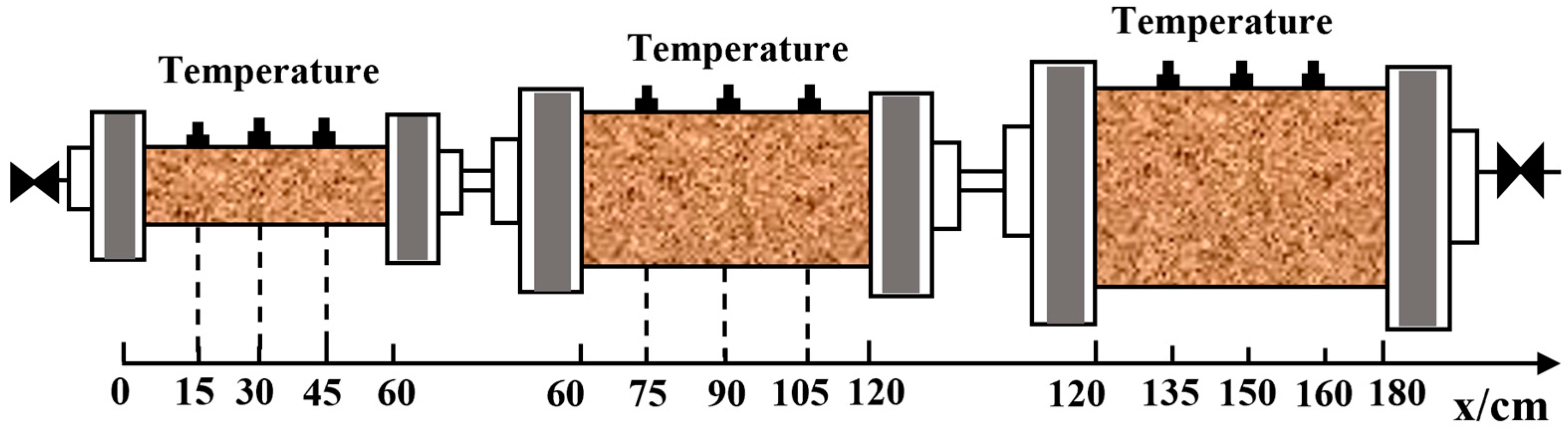
2.2. Apparatus for Huff and Puff Experiments

A one-dimensional three-stage sandpack model simulates heavy oil reservoirs. Each steel model has three temperature probes and can withstand 40 MPa and 300 °C. The sandpacks are 60 cm long with diameters of 2.5 cm, 6 cm, and 15 cm. This series simulates gas diffusion from a huff and puff well into the formation. The steam generator used is a high-precision SZ-1 from Feiyu, Changzhou, China. with a maximum temperature of 400 °C, a maximum steam flow of 20 mL/min, and a pressure range of 0–25 MPa. The ISCO double piston pump has a flow range of 0.01–25 mL/min, a pressure range of 0–70 MPa, a flow accuracy of ±0.3%, and a pressure accuracy of ±0.5%. The gas flowmeter controls CO2 flow, with a range of 0.1–250 mL/min, a maximum pressure of 10 MPa, and an accuracy of ±1% FS,;its model number is D08-1F. The high-precision CY201 pressure sensor from Chengdu KD Shengying, Chengdu, China, has a range of 0–30 MPa and an accuracy of 0.1%.

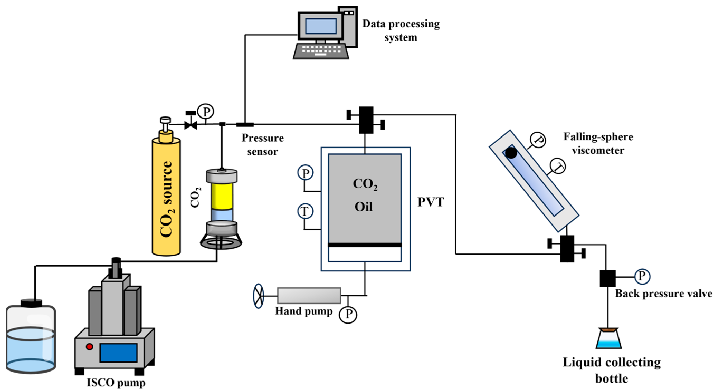
Apparatus for PVT Tests

High-temperature and high-pressure PVT phase analyzer: It has a working pressure of 0–40 MPa, a working temperature of 500 °C, adjustable temperature and heat preservation, magnetic impeller rotary stirring, and speed of 0–4000 rpm. PVT analyzer is an analytical device for determining the high-pressure physical properties of formation fluids, which can simulate the high-temperature and high-pressure environment of the formation and measure the volume–pressure change relationship, saturation pressure, compression coefficient, formation crude oil viscosity, formation crude oil density, etc. under the conditions of formation temperature, which is an important piece of equipment for experiments on improving the recovery rate of the oil field. Ball viscosimeter: Its model is CHY-I-type, it is from Shitian, Jiangsu, China. Its working pressure is 0~30 MPa, and its working temperature is 25~200 °C. The Falling Ball Viscometer is a simple and accurate dynamic viscosity measurement of fluids based on the Hoeppler measurement principle. The main core concept is to measure the time it takes for a falling ball to drop under gravity through a sample-filled tube tilted at a working angle to the desired position.

2.3. Pre-Experimental Test Preparation and Experimental Procedure

2.3.1. The Impact of Viscosity Reducers and CO2 on the Physical Properties of Heavy Oil

The PVT properties of the heavy oil and CO2 system and the heavy oil and CO2 mixed with water-soluble viscosity reducer system are tested by using a PVT analyzer, and the flow of the experimental setup is shown in Figure 2. The specific experimental sequence is outlined below.
  • Heat the experimental equipment and experimental medium to the designed temperature.
  • Fill the PVT meter with experimental liquid and experimental gas according to the design.
  • Turn the hand pump to inject water into the other side of the piston of the mixing container of the PVT meter and record the volume change.
  • Start the forward/reverse button to accelerate the dissolution and diffusion of the liquid and gas rest and record the pressure value when the pressure reaches equilibrium.
  • Repeat steps 1–4 to record multiple sets of data.
  • The experiment is completed, natural cooling of the experimental container to room temperature after the discharge of the experimental medium.
Here are the 4 specific tests.
(1)
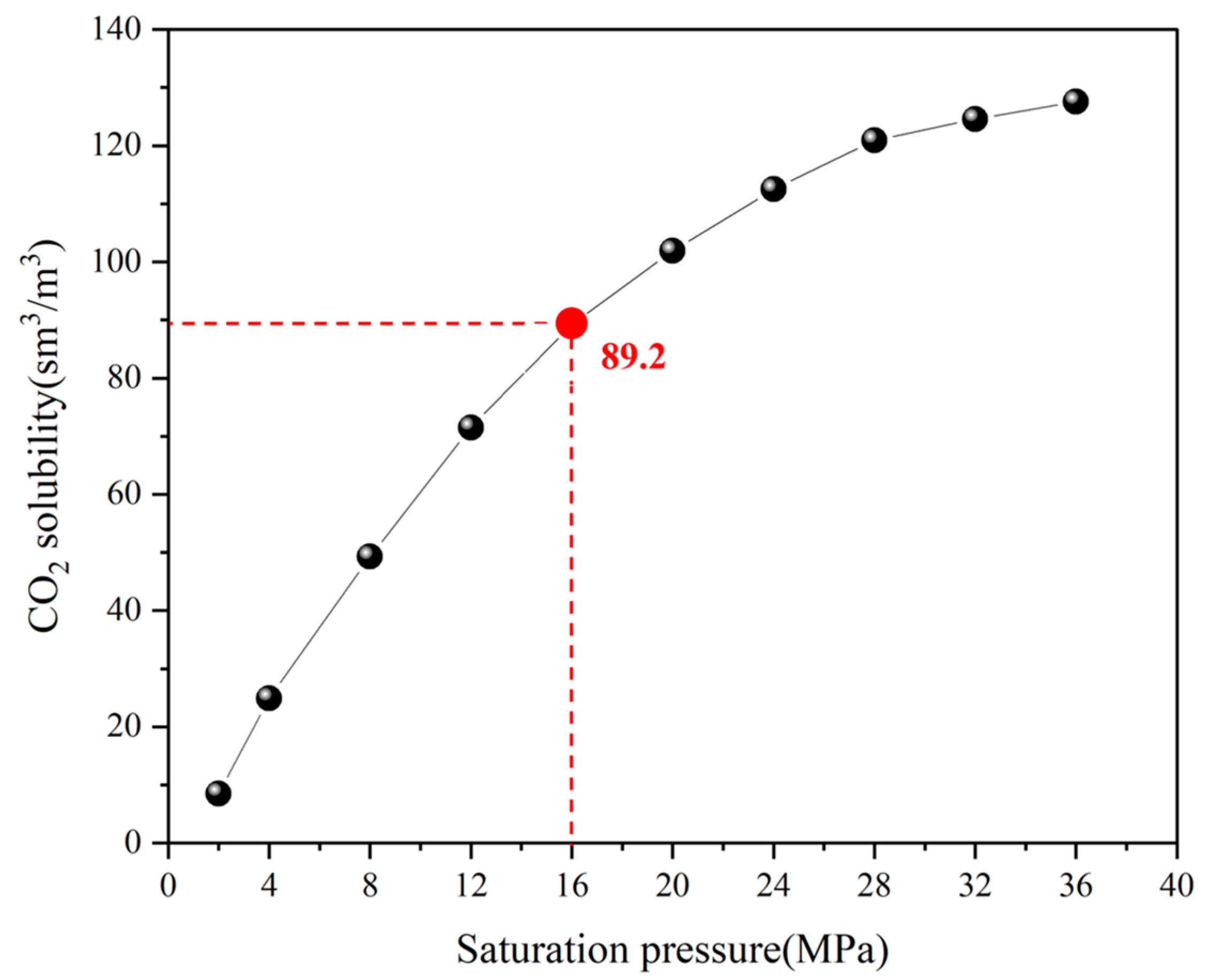
The solubility and viscosity changes of CO2 in heavy oil are measured at 68 °C and varying pressures. The pressure-solubility relationship is shown in Figure 3. The red line in Figure 3 refers that a saturation pressure of 16 MPa, CO2 solubility in heavy oil is 89.2 Sm3/m3, indicating that solubility increases with pressure. Under low pressure, the larger molecular gap in crude oil allows CO2 molecules to dissolve more easily. However, as saturation pressure rises, increased oil density due to compression reduces the molecular gap, making it more difficult for CO2 to dissolve in the oil.
(2)
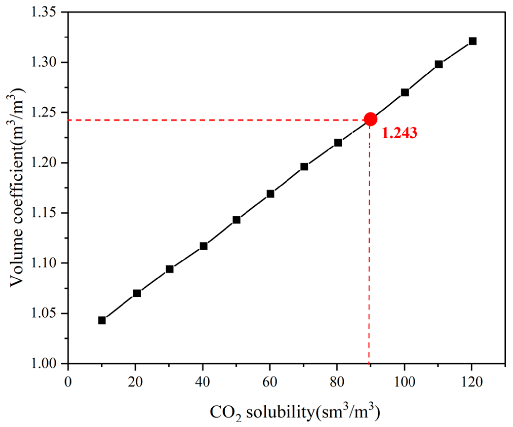
The volume expansion coefficients of heavy oil are analyzed at varying CO2 solubilities (10–110 Sm3/m3), revealing the relationship between the volume coefficient and CO2 solubility. Figure 4 shows that the volume coefficient of heavy oil increases linearly with rising CO2 solubility at 68 °C. Specifically, the red line in Figure 3 refers that the volume coefficient reaches approximately 1.234 at the maximum experimental CO2 solubility of 89.2 Sm3/m3 and about 1.32 at 120 Sm3/m3. This indicates that as CO2 solubility increases, the volume expansion of the formation oil also rises, enhancing its elasticity and suggesting a more significant oil increase effect with higher energy.
(3)
The viscosity of heavy oil is assessed at different CO2 solubilities. Figure 5 illustrates how heavy oil viscosity and the viscosity reduction rate change with varying CO2 solubilities at 68 °C. The results indicate that CO2 injection effectively reduces heavy oil viscosity. As CO2 solubility increases, crude oil viscosity rises. At a CO2 solubility of 90 Sm3/m3, the viscosity reduction rate is about 95.6%, and at 120 Sm3/m3, it reaches 96.3%.
(4)
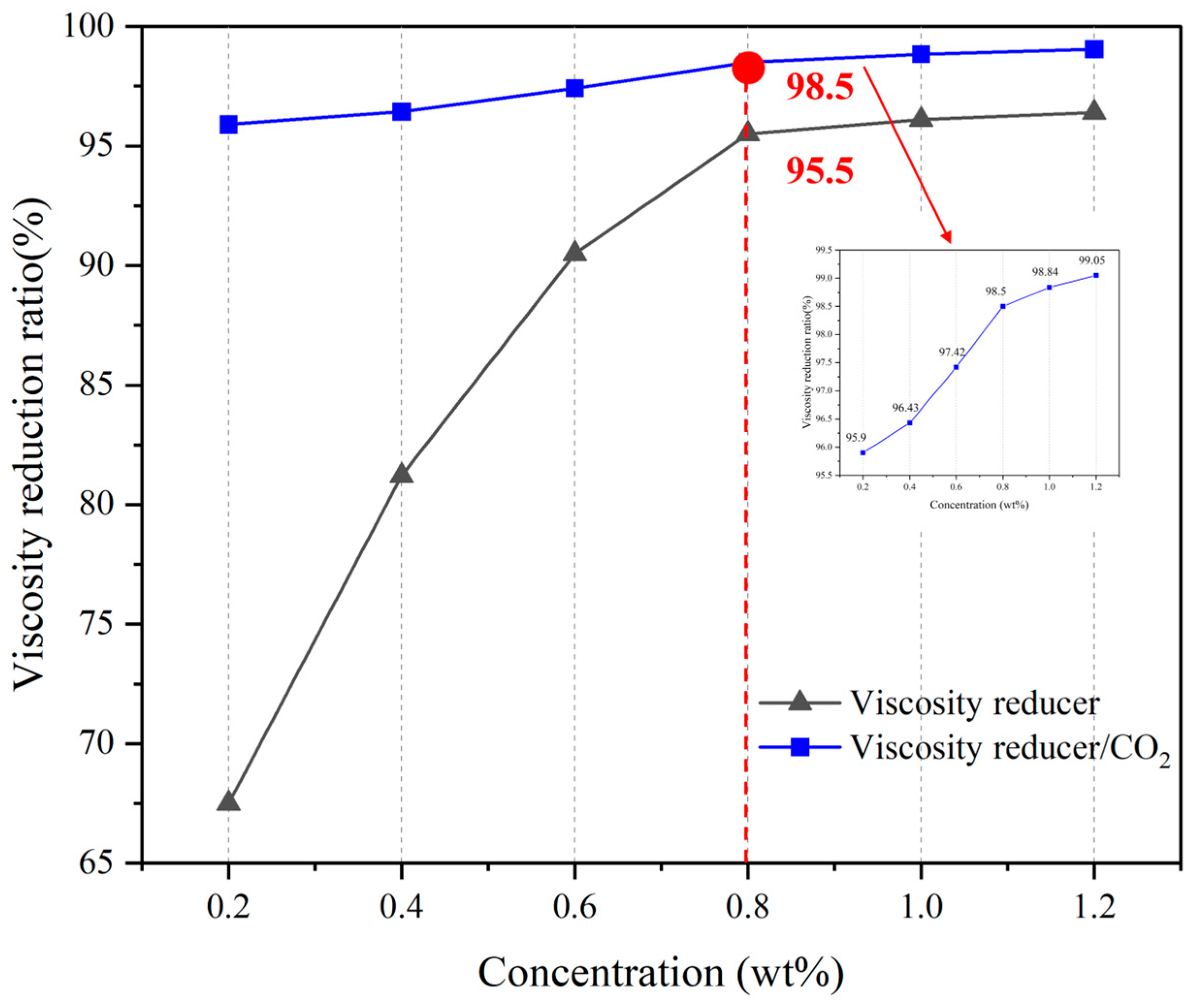
The effect of synergistic viscosity reduction using CO2 and a water-soluble viscosity reducer is studied. Seven viscosity reducers with concentrations of 0.2 wt%, 0.4 wt%, 0.6 wt%, 0.8 wt%, 1.0 wt%, 1.2 wt%, and 1.4 wt% were added to heavy oil. The viscosity is measured at 16 MPa, 68 °C, and a CO2 dissolved gas–oil ratio of 89.2 Sm3/m3. Figure 6 shows the viscosity reduction rate with the combined use of the water-soluble viscosity reducer and CO2 at the specified ratio. Results indicate that increasing viscosity reducer concentration correlates with higher viscosity reduction rates. Between concentrations of 0.2 wt% and 1.2 wt%, the rate rises rapidly; however, above 0.8 wt%, the increase slows. The best economy of effect is at a concentration of 0.8 wt%. Notably, the synergistic viscosity reduction rate reaches 98.5% at 0.8 wt%, compared to 95.5% for the viscosity reducer alone.

2.3.2. Huff and Puff Experiment

The huff and puff experiment differs from the coreflood experiments in that the injection end and production end of the huff and puff recovery method are the same port. In this study, the small-diameter sandpack (numbered 1) serves as the injection end and the production outlet, while the other end of the largest-diameter sandpack (numbered 3) is sealed to simulate the end of the external boundary. The experimental flow chart is presented in Figure 7. The recovery enhancement mechanism of alternating hot and cold huff and puff of steam and CO2/viscosity reducer was elucidated through experimentation, and the feasibility of this method in developing heavy oil reservoirs was corroborated. The specific experimental steps are as follows.
(1)
The sand-fill model should be prepared by filling the sandpack with the prepared sand mixture. The airtightness of the model should then be checked, and the dry weight of the core tube should be measured.
(2)
The sandpacks are evacuated for a period of four hours and then saturated with water. Following saturation, the core tubes are weighed, and the porosity is calculated based on the weight difference. Permeability is tested by injecting a constant flow of water by Darcy’s law.
(3)
Heavy oil is injected into the core via a plunger pump, and each of the three sandpacks is saturated with oil at a rate of 1 mL/min until no additional water flows out. Once saturation is complete, the three sandpacks are assembled and placed in a thermostat. The tubes are maintained at 68 °C for 12 h. The saturation process is conducted at a rate of 1 mL/min until no further water is observed to flow out. The three sandpacks are then assembled and placed in a thermostat for an additional 12 h at 68 °C.
(4)
Install the experimental equipment according to the flow chart. Turn on the steam generator to preheat in advance, the temperature of the steam generator is set to 300 °C. When the temperature of the sandpack and the steam generator reaches a stable temperature, start the experiment. According to the experimental design, set the steam injection rate to 3 mL/min; the steam injection rate is equivalent water; when the pressure sensor at the inlet end of the sandpack reaches 16 MPa, stop the injection and record the PV number of injected steam. Close all valves and soak for 200 min, open the inlet valve, set the back pressure to 2 MPa, record the temperature at the time of opening the well, and keep the downward pressure mining at a decreasing rate of 0.2 MPa/min, so that the oil and water spout out, until the pressure in the sandpack is reduced to the point that there is no fluid coming out of the tube after the back pressure is applied.
(5)
The CO2/viscosity reducer huff and puff procedure begins with the injection of a water-soluble viscosity reducer at an optimal concentration into the sandpack at a flow rate of 0.5 mL/min, with an injection volume of 0.1 PV. Subsequently, CO2 is injected at a rate of 10 mL/min, and the injection is terminated when the pressure sensor at the inlet end reaches 16 MPa. The volume of injected CO2 is recorded. Once all the valves have been closed, the sandpack is allowed to simmer for 200 min. The inlet valve should then be opened, the back pressure is set at 2 MPa, and the downward pressure extraction is maintained at a rate of 0.2 MPa/min. This process continues until the pressure in the sandpack is reduced to a point where no further fluid is extracted. The extracted fluid is then collected at the outlet end.
(6)
Steps (4) and (5) are repeated until six cycles of alternating throughput (H + C + H + C + H + C) are completed. In these cycles, H represents steam huff and puff, while C represents CO2 composite huff and puff. Following this, step (4) is repeated for pure steam huff and puff until six cycles of huff and puff (H + H + H + H + H + H) are completed. Detailed parameters of the two groups of huff and puff experiments are shown in Table 1.

3. Experimental Results and Discussion

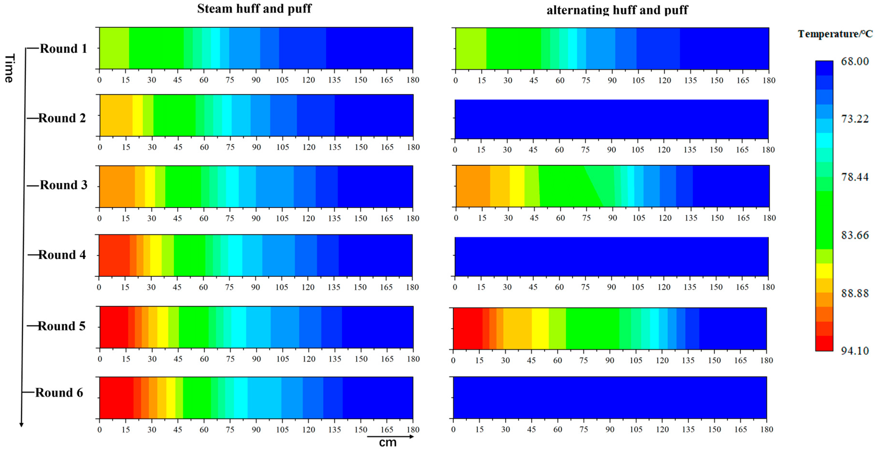
3.1. Temperature Field Analysis

Since the viscosity of heavy oil is strongly affected by temperature, it is important to study the temperature for extraction. In the huff and puff experiment, each sandpack has three temperature measurement points. These nine measurement points are represented on a one-dimensional coordinate, as shown in Figure 8, and their positions are at x = 15 cm, x = 30 cm, x = 45 cm (#1 sandpack), x = 75 cm, x = 90 cm, x = 105 cm (#2 sandpack), x = 135 cm, x = 150 cm, and x = 165 cm (#3 sandpack). The temperature at the beginning of production is recorded for each cycle. The temperature field is shown in Figure 9.
In the pure steam huff and puff process, temperatures at x = 15 cm and x = 30 cm at the front of the sandpack increased significantly with increasing cycles, where x = 15 cm ranged from 85.2 °C to 94.1 °C within six cycles. This increase occurs because residual heat from previous cycles remains in the sandpack. However, beyond x = 90 cm, the temperature does not change much with each cycle (Figure 9). This mainly happens because, during steam huff and puff, the steam heat flows quickly to the surrounding medium to dissipate. Additionally, heavy oil has a high viscosity. As a result, the steam only affects the first half of the reservoir model. Heat has difficulty reaching the second half, as shown in Figure 10b,e.
In the steam–CO2/viscosity reducer huff and puff process, CO2 in the reservoir pores raises the temperatures inside the sandpack. In the third cycle, the temperatures at x = 15 cm and x = 30 cm are 89.4 °C and 87.7 °C, respectively (see Figure 9). By the fifth cycle, these temperatures increase to 93.4 °C and 88.5 °C. Although there is no sustained supply of heat from the steam, CO2 still helps enhance heat within the sandpacks. This effect is due to CO2’s low thermal conductivity and non-condensable nature, which reduces heat loss by limiting heat exchange between the steam and rock matrix during propagation, as shown in Figure 10c. Additionally, CO2 helps to advance the heat transport distance. In the initial, third, and fifth cycles, the temperature of about 80 °C is extended to x = 60 cm, x = 90 cm, and x = 105 cm, respectively. Compared to pure steam huff and puff, the fifth cycle of the alternate method advances an extra 45 cm (Figure 9), which improves heat distribution and heating more residual oil. The CO2 huff and puff expands the wave range and improves steam flow by opening seepage channels, as shown in Figure 10f. Additionally, CO2’s thermal expansion pushes steam deeper into the reservoir. This enhances heat distribution, as illustrated in Figure 10d. Together, these factors increase steam sweep efficiency and raise temperatures in deeper reservoir areas.

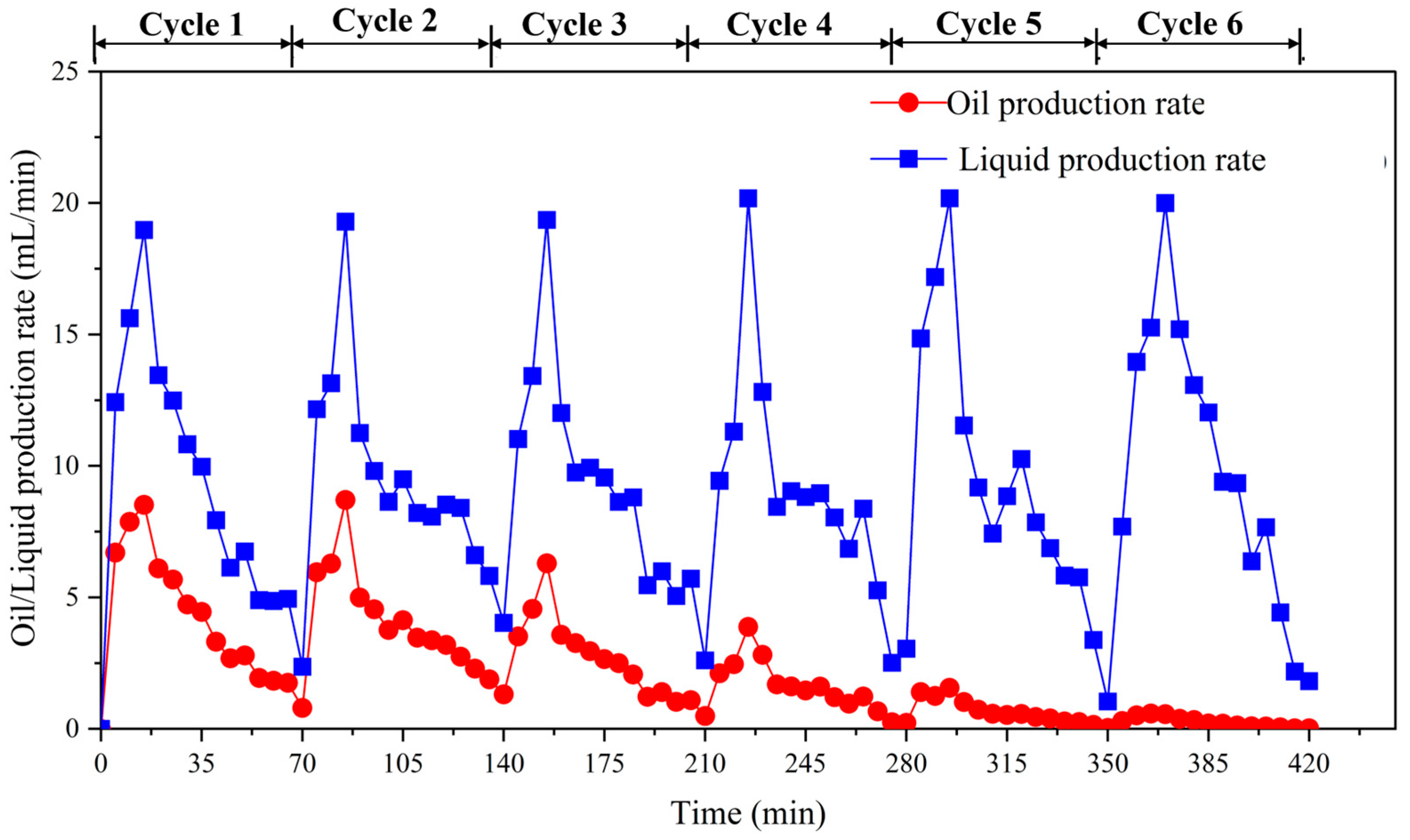
3.2. Analysis of Production Dynamics

Figure 11 illustrates the relationship between the oil production rate and the liquid production rate of the steam huff and puff over time. Figure 12 depicts the relationship between oil production and the liquid production rate of steam–CO2/viscosity reducer huff and puff over time. The analysis of the two graphs shows a similar trend; in the same cycle, both steam huff and puff and steam–CO2/viscosity reducer huff and puff lead to an initial increase in oil and liquid production. After that, the production rates decline. Meanwhile, the water cut gradually increases during the one cycle.
In the pure steam huff and puff process, steam is injected up to 16 MPa in each cycle, so the same amount of energy is added in each cycle. This explains the approximately equal maximum production rate of about 20 mL/min for each cycle in Figure 11. The oil production rate in the first two cycles of pure steam huff and puff is high. The peak oil production rates are 8.5 mL/min and 8.7 mL/min, respectively. The average water cuts are low at 56.9% and 59%, with oil productions of 296 mL and 283 mL, respectively. It can be inferred that the primary contribution to oil production occurs in the first two cycles. The oil recovery degrees for the first and second cycles are 10.5% and 10.05%, respectively. As the number of cycles increases, the peak oil production and overall oil production decrease rapidly after the third cycle. The oil production rate is very low by the sixth cycle. Moreover, the water cut of the output liquid becomes very high, with an average of 97.8%. The oil recovery degree in this cycle is also very low. Thus, it can be concluded that the steam huff and puff method has reached its limit.
In the steam–CO2/viscosity reducer huff and puff process, the peak liquid production in the CO2/viscosity reducer huff and puff phase is lower than in the steam huff and puff phase. This is because the CO2/viscosity reducer phase produces not only liquids but also a large amount of CO2 with the same injection energy (Figure 12). Figure 13 shows that the water cut in the steam–CO2/viscosity reducer huff and puff is 71.9% in the middle of the fifth cycle, which is 22.1% lower than the 94% water cut in the pure steam huff and puff. Even after the sixth cycle, the steam–CO2/viscosity reducer huff and puff shows continued production, indicating that exploitation has not yet reached its limit.
Moreover, the CO2/viscosity reducer huff and puff phase significantly reduces the water cut of the produced fluids. The lowest water cut values in the second, fourth, and sixth cycles are 25.4%, 31.2%, and 41.3%, respectively. This improvement is attributed to the limited amount of water injected into the system, which results in enhanced production efficiency. In the second, fourth, and sixth cycles of alternating huff and puff, the average water cut progressively increases to 28.55%, 43.35%, and 56.62%, respectively. The increase in water cut is due to the extraction of more heavy oil and the increase in bound water in the pore space. Furthermore, the peaks in oil and liquid production rates declined during these cycles due to a decrease in the CO2 gas–liquid displacement ratio and increased CO2 gas production.
In the following, we will explain the reasons for the higher steam–CO2/viscosity reducer huff and puff enhanced recovery from a mechanistic point of view. At the end of the steam huff and puff production process, the steam temperature near the well decreases, leading to an increase in heavy oil viscosity and a decline in both reservoir pressure and elastic energy. This scenario results in heavy oil plugging the region. The combination of reduced energy and higher viscosity of the heavy oil results in lower oil production (Figure 14b).
In CO2/viscosity reducer huff and puff, injecting a viscosity reducer first during the extraction process can transform water-in-oil emulsions into oil-in-water emulsions. This alteration enhances the flow of heavy oil, alleviates near-well blockages, and facilitates the transportation of heavy oil to the surface, as demonstrated in Figure 14c. Additionally, the dissolution of CO2 in heavy oil further decreases viscosity and expands the volume of heavy oil, thereby increasing elastic drive energy (Figure 15b). At this stage of production, the post-injection of CO2 advances the viscosity reducer over a greater distance, resulting in a larger area of viscosity reduction in the heavy oil. The emulsion formed by the front-edge viscosity reducer effectively seals the CO2 flow path, thereby expanding the CO2 reach and improving oil recovery (Figure 15c,d).
From the data comparison in Figure 16, the alternating huff and puff method has a higher recovery rate. The differences between the two methods are as follows: The productivity of the steam–CO2/viscosity reducer huff and puff in the third and fifth cycles maintains higher production levels, with recovery rates of 9.64% and 5.35%, respectively. In contrast, the productivity of pure steam huff and puff in the third cycle starts to decline, with a recovery rate of 6.49%. After the fifth cycle, extraction approaches its limit, with a total recovery in the sixth cycle of only 0.62%. Ultimately, the final oil recovery for the steam–CO2/viscosity reducer huff and puff is 49.13%, which is 15.89% higher than the final oil recovery of 33.24% for the steam-only huff and puff.

3.3. CO2 Storage Efficiency During Alternating Huff and Puff Processes

As a result of the huff and puff process, CO2 is stored in various states, as illustrated in Figure 17. The majority of the CO2 is retained in the pore space of the reservoir in its free state [49]. Concurrently, within the high-pressure environment beneath the reservoir, the CO2 is dissolved in subsurface liquids, including heavy oil and formation water, in the form of a dissolved state [50]. Furthermore, CO2 is adsorbed at the interface between the subsurface organic matter and mineral surfaces, resulting in the formation of an adsorbed state [51].
This paper presents a study on CO2 storage efficiency during the alternating huff and puff process, conducted through experiments. The potential for CO2 storage during huff and puff operations is analyzed in depth using the storage rate formula.
η = V i V p V i
where η is the rate of CO2 storage rate; V i is the volume of CO2 injection, cm3; and V p is the volume of CO2 production, cm3.
The CO2 injection and CO2 output during the huff and puff process were converted to volumes at the experimental pressure of 16.00 MPa. The CO2 injection volume was measured using a gas flow meter. The CO2 production volume is divided into two types: the volume of CO2 separated by a gas–liquid separation device, also measured by a gas flow meter and the CO2 present in the form of bubbles in the output foam oil. The main reason is that during the static separation of heavy oil and the precipitation of dissolved CO2, the output oil becomes foam oil. The amount of CO2 dissolved in the output oil at room temperature and pressure is very small and has fully precipitated. Additionally, the dissolved CO2 mass in the water is negligible. The volume of CO2 in the form of bubbles mixed in the oil is calculated as follows:
V c o + V o = V p o V c o × ρ c + V o 2 × ρ o = M p o
where ρ c is the density of CO2 (at room temperature and pressure), which, consulting the literature, is known to be 1.964 g/L, ρ o is the density of the experimental heavy oil, V c o is the volume of CO2 in the output foam oil, and V o is the volume of the actual oil in the output foam oil. V p o is the volume of the actual output foam oil, which can be measured by a measuring cylinder.
As shown in Figure 18, the storage rate of the second cycle was the highest at 76.8%. With the increase in alternating huff and puff cycles, the storage rate of CO2 gradually decreases. The storage rates in the fourth and sixth cycles are 36.9% and 15.2%, respectively. In addition, some CO2 is also produced in the steam huff and puff stage. As the CO2 injected in the early stage can be more dissolved in the heavy oil, the CO2 storage capacity is highest initially. After several cycles of huff and puff, with the increase in CO2 solubility in heavy oil, the CO2 in the free pore space also tends to be saturated, resulting in a gradual decrease in the CO2 sequestration rate. Finally, the accumulated final storage of CO2 was 6.628 mL during six cycles of steam–CO2/viscosity reducer huff and puff.

4. Conclusions

This paper proposes a development method combining alternating steam and CO2/viscosity reducer huff and puff. To uncover its IOR mechanism, novel simulation experiments on pure steam and alternating huff and puff were compared. Simultaneously, the CO2 storage rates of this novel IOR method were estimated and predicted. The research findings lead to the following key conclusions.
(1)
At a CO2 solubility of approximately 89.2 Sm3/m3, the volume coefficient of the target heavy oil is about 1.234, with a viscosity reduction rate of 95.6% due to CO2. The optimal concentration of the water-soluble viscosity reducer is 0.8 wt%, achieving a viscosity reduction rate of 95.5%. When combined, the synergistic effect of CO2 and the viscosity reducer enhances the viscosity reduction rate to 98.5%.
(2)
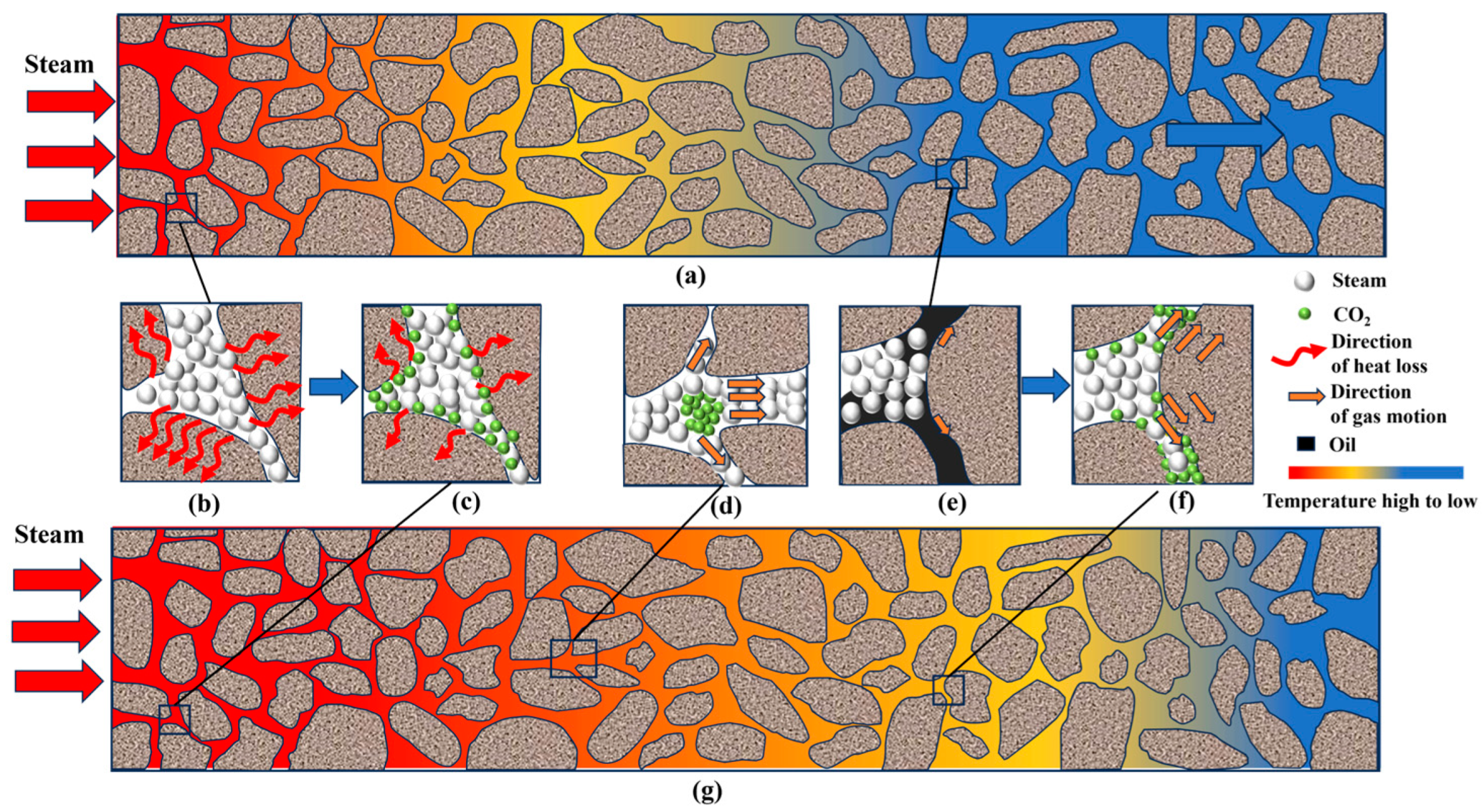
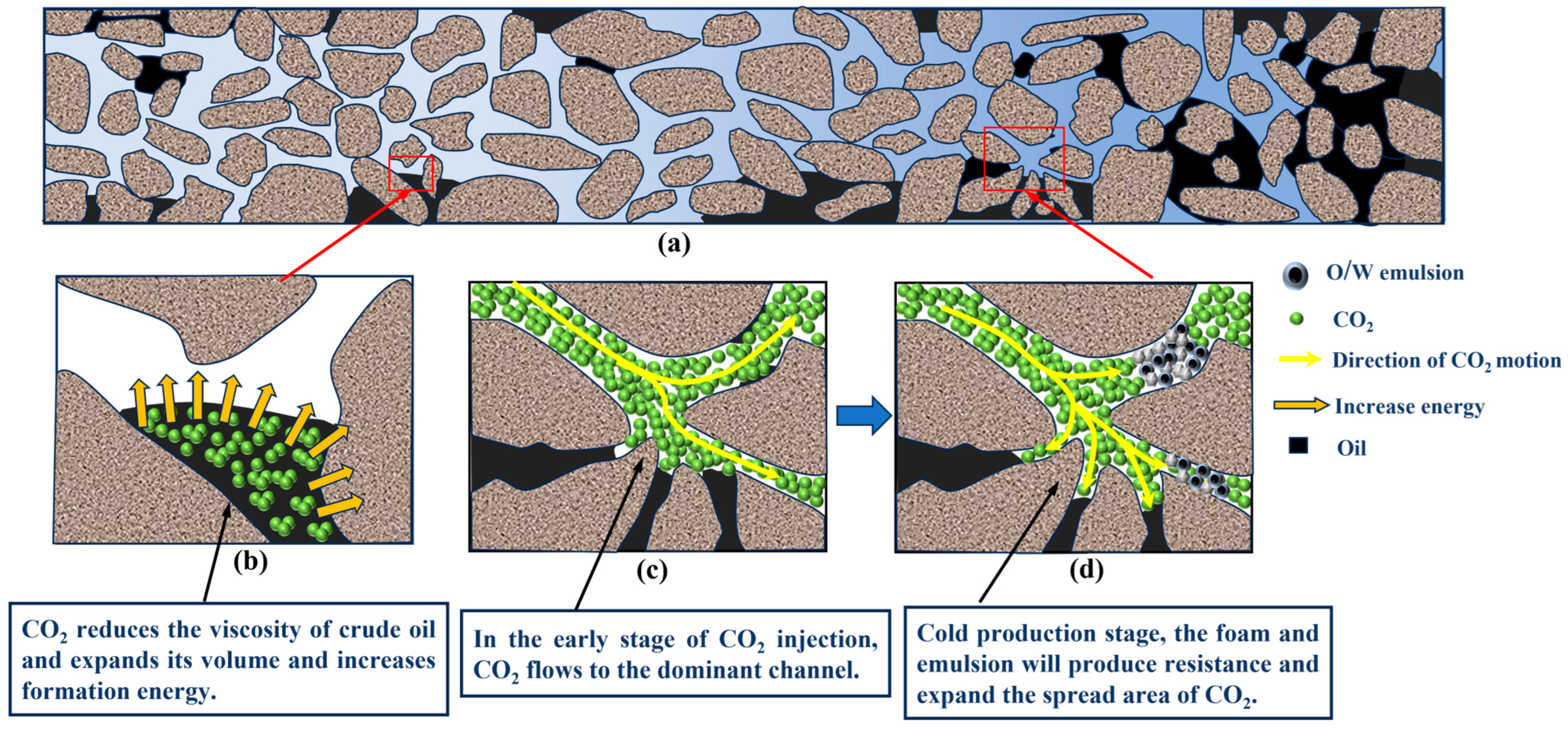
The insulation effect of CO2 as a non-condensable gas, combined with its thermal expansion push effect, enhances recovery. Additionally, the cold production of CO2/viscosity huff and puff opens seepage channels for subsequent thermal recovery, reducing steam seepage resistance and extending the steam heating range. Therefore, steam–CO2/viscosity reducer huff and puff have a longer steam reach than pure steam huff and puff. In the fifth cycle of alternate huff and puff, the high temperature of about 80 °C is pushed forward by an extra 45 cm, with the heat spreading farther.
(3)
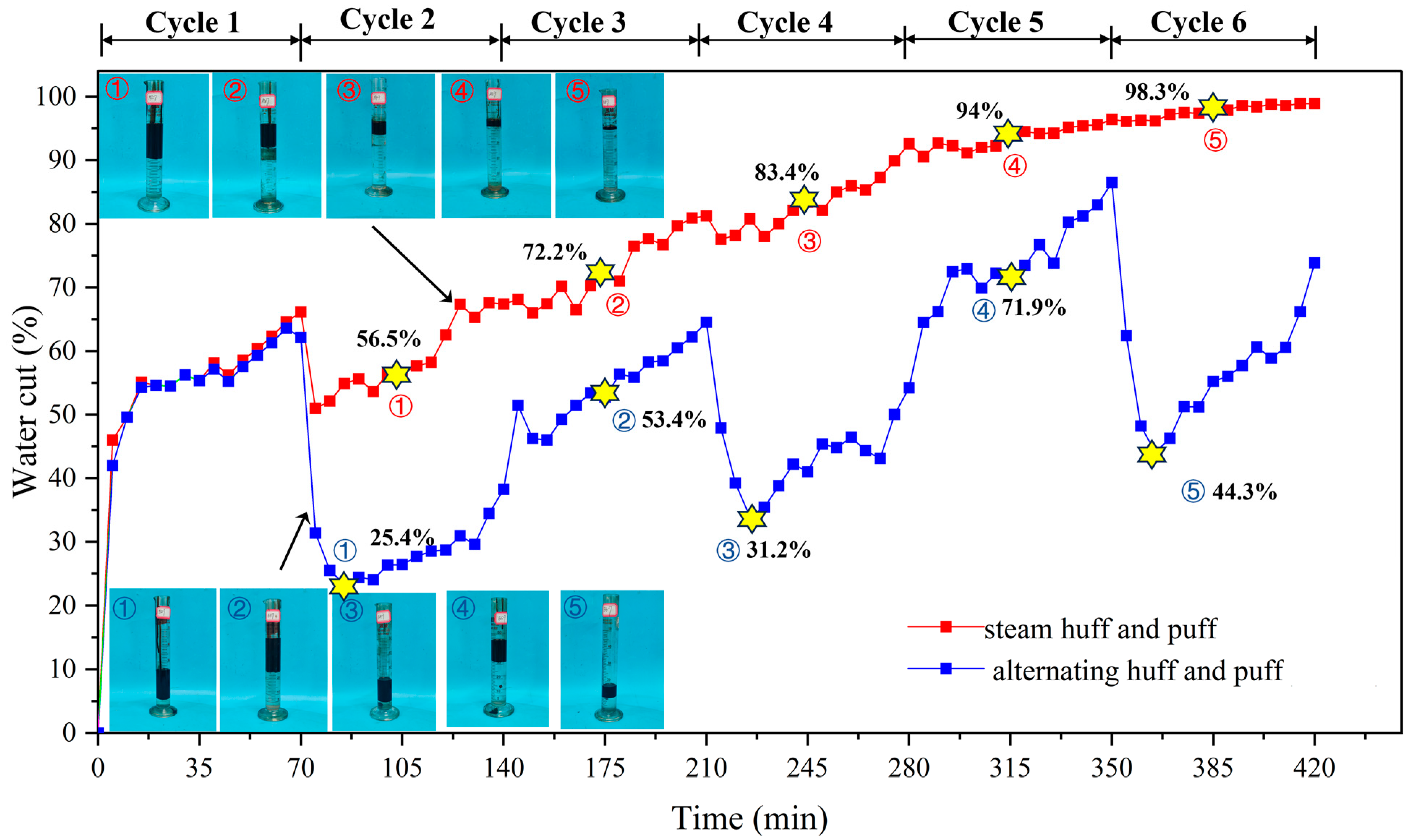
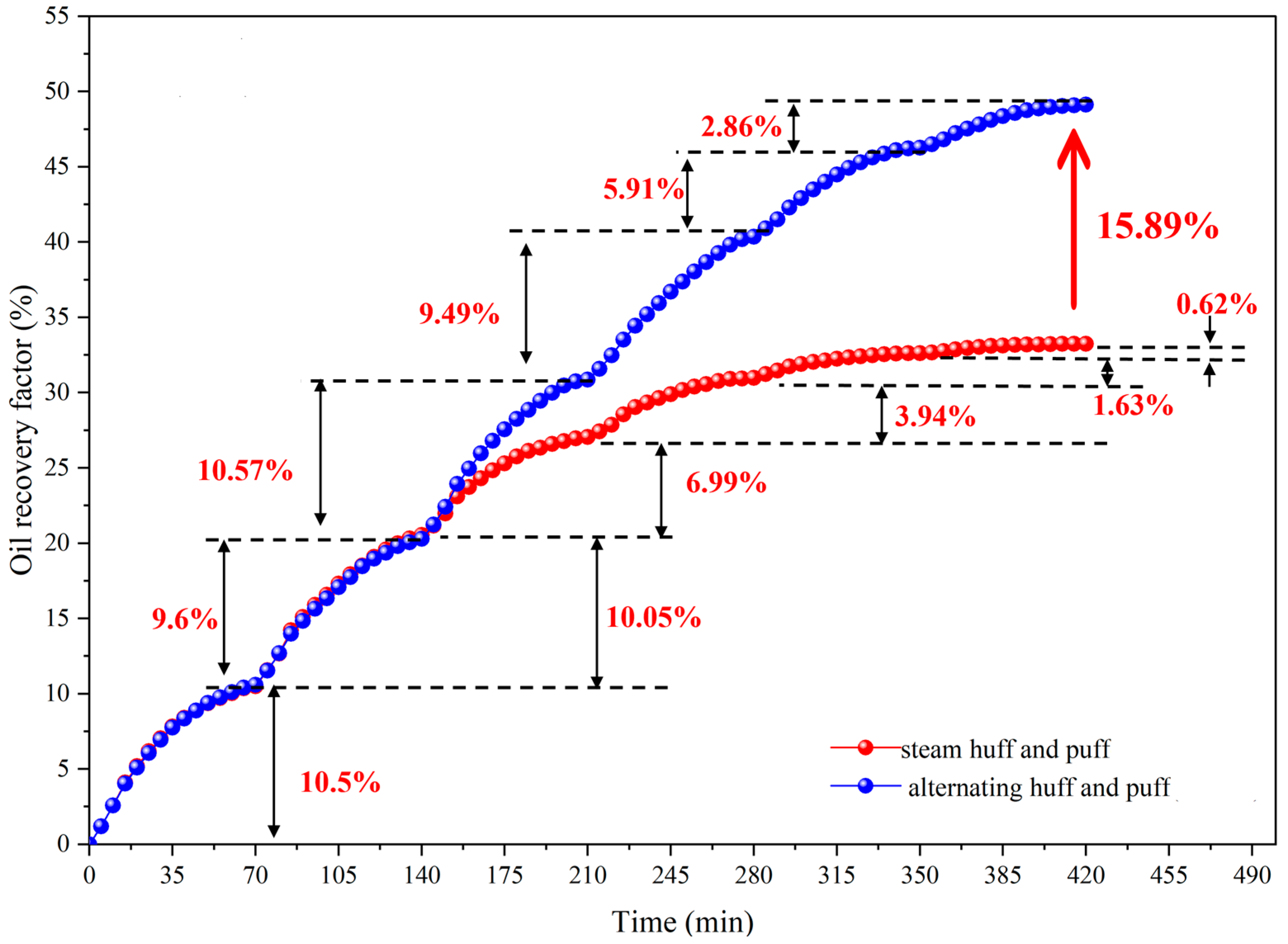
Due to the viscosity reducer’s ability to alleviate blockage in the near-well zone, CO2 dissolved in heavy oil decreases viscosity and enhances elastic repulsion energy. Additionally, the emulsion formed by the viscosity reducer seals the dominant CO2 flow channels, increasing the CO2 wave size. Therefore, the CO2/viscosity reducer huff and puff method significantly reduces the water cut during the cold production stage and extends the production cycle after subsequent thermal recovery. The IOR of the steam–CO2/viscosity reducer huff and puff method is 15.89% higher than pure steam huff and puff.
(4)
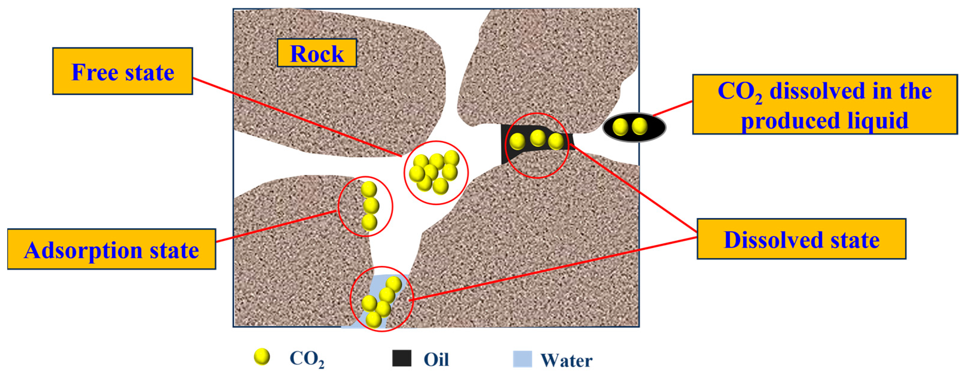
In the early stage of CO2/viscosity reducer huff and puff, the CO2 storage rate was the highest, 76.8%. In the late stage of huff and puff, the sequestration rate of huff and puff gradually decreased due to the increase of CO2 solubility in heavy oil, and the free pore space became saturated with CO2. After six cycles, the sequestration rate of CO2 was only 15.2%.

Author Contributions

Conceptualization, W.S. and L.T.; methodology, L.T.; software, G.Y.; investigation, G.Y. and W.S.; resources, L.T.; data curation, J.B., Z.X. and N.Z.; writing—original draft preparation, G.Y. and L.T.; writing—review and editing, W.S.; visualization, W.S. and Q.Z.; supervision, Y.S. and C.W.; project administration, W.S. and L.C.; funding acquisition, W.S. All authors have read and agreed to the published version of the manuscript.

Funding

This work was supported by the Open Fund (PLN202415) of the State Key Laboratory of Oil and Gas Reservoir Geology and Exploitation (Southwest Petroleum University). The corresponding author thanks the SINOPEC Science and Technology Research Program “Flowability control and enhanced oil recovery technology through combined flooding and drainage in Edge and Bottom Water Heavy Oil Reservoirs” (No. P24081) and the Natural Science Research Project of Jiangsu Higher Education Institutions (No. 23KJB440001).

Data Availability Statement

The original contributions presented in this study are included in the article. Further inquiries can be directed to the corresponding authors.

Conflicts of Interest

Authors Yong Song and Lili Cao were employed by the company Petroleum Exploration and Production Research Institute, Sinopec. The remaining authors declare that the research was conducted in the absence of any commercial or financial relationships that could be construed as a potential conflict of interest. The company had no role in the design of the study; in the collection, analyses, or interpretation of data; in the writing of the manuscript, or in the decision to publish the results.

References

  1. Wang, L.; Guo, J.; Li, C.; Xiong, R.; Chen, X.; Zhang, X. Advancements and future prospects in in-situ catalytic technology for heavy oil reservoirs in China: A review. Fuel 2024, 374, 132376. [Google Scholar] [CrossRef]
  2. Wang, L.; Pang, Z.; Jin, Y.; Liu, D. Thermodynamic Characteristics of cold and hot non-condensable gases simultaneously flowing along vertical wellbore. J. Petrol. Sci. Eng. 2022, 208, 109451. [Google Scholar] [CrossRef]
  3. Zhao, F.; Liu, Y.; Lu, N.; Xu, T.; Zhu, G.; Wang, K. A review on upgrading and viscosity reduction of heavy oil and bitumen by underground catalytic cracking. Energy Rep. 2021, 7, 4249–4272. [Google Scholar] [CrossRef]
  4. Wang, Z.; Li, S.; Li, Z. A novel strategy to reduce carbon emissions of heavy oil thermal recovery: Condensation heat transfer performance of flue gas-assisted steam flooding. Appl. Therm. Eng. 2022, 205, 118076. [Google Scholar] [CrossRef]
  5. Guo, K.; Li, H.; Yu, Z. In-situ heavy and extra-heavy oil recovery: A review. Fuel 2016, 185, 886–902. [Google Scholar] [CrossRef]
  6. Sun, X.; Cai, J.; Li, X.; Zheng, W.; Wang, T.; Zhang, Y. Experimental investigation of a novel method for heavy oil recovery using supercritical multithermal fluid flooding. Appl. Therm. Eng. 2021, 185, 116330. [Google Scholar] [CrossRef]
  7. Liu, S.; Wu, X.; Li, Y.; Cui, S.; Shen, X.; Tan, G. Hydrophobic in-situ SiO2-TiO2 composite aerogel for heavy oil thermal recovery: Synthesis and high temperature performance. Appl. Therm. Eng. 2021, 190, 116745. [Google Scholar] [CrossRef]
  8. Soler, C.A.C.; Malagueta, D.C.; Martin, C.A.G. Feasibility of implementation of solar thermal energy in steam-assisted gravity drainage (SAGD) in extra-heavy oil field in Colombia. Geoenergy Sci. Eng. 2023, 222, 211463. [Google Scholar] [CrossRef]
  9. Hou, J.; Wei, B.; Du, Q.; Wang, J.; Wang, Q.; Zhang, G. Production prediction of cyclic multi-thermal fluid stimulation in a horizontal well. J. Petrol. Sci. Eng. 2016, 146, 949–958. [Google Scholar] [CrossRef]
  10. Tian, Z.; Gan, W.; Qi, Z.; Tian, M.; Gao, W. Experimental study of organic Rankine cycle with three-fluid recuperator for cryogenic cold energy recovery. Energy 2022, 242, 122550. [Google Scholar] [CrossRef]
  11. Cao, H.; Li, Y.; Gao, W.; Cao, J.; Sun, B.; Zhang, J. Experimental investigation on the effect of interfacial properties of chemical flooding for enhanced heavy oil recovery. Colloids Surf. A 2023, 677, 132335. [Google Scholar] [CrossRef]
  12. Zamani, A.M.; Moslemi, A.; Hassani, K. Experimental investigation into effects of the natural polymer and nanoclay particles on the EOR performance of chemical flooding in carbonate reservoirs. Petrol. Sci. 2024, 21, 951–961. [Google Scholar] [CrossRef]
  13. Coskuner, G.; Naderi, K.; Babadagli, T. An enhanced oil recovery technology as a follow up to cold heavy oil production with sand. J. Petrol. Sci. Eng. 2015, 133, 475–482. [Google Scholar] [CrossRef]
  14. He, H.; Li, Q.; Zheng, H.; Liu, P.; Tang, J.; Ma, Y. Simulation and evaluation on enhanced oil recovery for steam huff and puff during the later phase in heavy oil Reservoir—A case study of block G in Liaohe oilfield, China. J. Pet. Sci. Eng. 2022, 219, 111092. [Google Scholar] [CrossRef]
  15. Zhang, N.; Liu, W.; Zou, X.; Wang, S.; Sun, Q.; Li, B.; Li, S.; Bhusal, A.; Wang, S.; Li, Z. Experimental study on thermochemical composite system huff-n-puff process in ultra-heavy oil production. Fuel 2022, 332, 126014. [Google Scholar] [CrossRef]
  16. Wan, T.; Wang, X.; Jing, Z.; Gao, Y. Gas injection assisted steam huff-n-puff process for oil recovery from deep heavy oil reservoirs with low-permeability. J. Petrol. Sci. Eng. 2022, 12, 4631. [Google Scholar] [CrossRef]
  17. Shedid, S.A. Influences of fracture orientation on oil recovery by water and polymer flooding processes: An experimental approach. J. Pet. Sci. Eng. 2020, 185, 106613. [Google Scholar] [CrossRef]
  18. Wang, X.; Wang, J.; Qiao, M. Horizontal well, nitrogen and viscosity reducer assisted steam huff and puff technology: Taking super heavy oil in shallow and thin beds, Chunfeng Oilfield, Junggar Basin, NW China, as an example. Pet. Explor. Dev. 2013, 40, 104–110. [Google Scholar] [CrossRef]
  19. Nian, Y.L.; Han, B.B.; Cheng, W.L. Experimental study on combination hot water-CO2-chemical flooding with effects on oil recovery and heat transfer. Appl. Therm. Eng. 2020, 166, 114683. [Google Scholar] [CrossRef]
  20. Ebrahimzadeh, E.; Matagi, J.; Fazlollahi, F.; Baxter, L.L. Alternative extractive distillation system for CO2–ethane azeotrope separation in enhanced oil recovery processes. Appl. Therm. Eng. 2016, 96, 39–47. [Google Scholar] [CrossRef]
  21. Jia, B.; Tsau, J.S.; Barati, R. Role of Molecular Diffusion in Heterogeneous, Naturally Fractured Shale Reservoirs during CO2 Huff-N-Puff. J. Petrol. Sci. Eng. 2018, 164, 31–42. [Google Scholar] [CrossRef]
  22. Zakin, J.L.; Pinaire, R.; Borgmeyer, M.E. Transport of oils as oil-in-water emulsions. J. Fluids Eng. 1979, 101, 100–104. [Google Scholar] [CrossRef]
  23. Sullivan, A.P.; Kilpatrick, P.K. The effects of inorganic solid particles on water and crude oil emulsion stability. Ind. Eng. Chem. Res. 2022, 41, 3389–3404. [Google Scholar] [CrossRef]
  24. Zhou, X.; Zeng, F.; Zhang, L.; Jiang, Q.; Yuan, Q.; Wang, J.; Zhu, J.; Huang, X. Experimental and mathematical modeling studies on foamy oil stability using a heavy oil–CO2 system under reservoir conditions. Fuel 2020, 264, 116771. [Google Scholar] [CrossRef]
  25. Wang, Z.; Lu, H.; Zhao, C.; Zhu, E. Investigating phase dynamics of reservoir fluids in CO2 huff-n-puff enhanced oil recovery. Geoenergy Sci. Eng. 2024, 238, 212925. [Google Scholar] [CrossRef]
  26. Yang, Y.; Song, H.; Li, Y.; Liu, F.; Zhang, Q.; Wang, J.; Imani, G.; Zhang, L.; Sun, H.; Zhong, J.; et al. Microscopic mechanism of CO2 huff-n-puff promoting shale oil mobilization in nanopores. Fuel 2024, 371, 131841. [Google Scholar] [CrossRef]
  27. Xu, R.; Zeng, K.; Zhang, C.; Jiang, P. Assessing the feasibility and CO2 storage capacity of CO2 enhanced shale gas recovery using Triple-Porosity reservoir model. Appl. Therm. Eng. 2017, 115, 1306–1314. [Google Scholar] [CrossRef]
  28. Yang, F.; Zhu, W.; Yu, X.; Tang, Y.; Shi, W. Application of in-situ generation gas huff-n-puff process in W5 heavy oil reservoir of Jiangsu Oilfield. Complex Hydrocarb. Reserv. 2013, 6, 71–75. [Google Scholar]
  29. Wang, L.; Shao, Y.; Chen, X.; Wang, C.; Yang, X.; Doranehgard, M.H.; Che, D. Thermofluidic characteristics for a novel complementary adsorption-absorption post-combustion partial CO2 capture system. Appl. Therm. Eng. 2023, 226, 120301. [Google Scholar] [CrossRef]
  30. Shi, Y.; Wu, B.; Wang, H.; Li, Y.; Liu, Z.; Xu, C.; Qin, J.; Li, Y.; Song, Z.; Liu, H. Insights into CO2 huff-n-puff mechanisms from laboratory experiment and single-well pilot test in the Lucaogou tight oil reservoir, Jimsar sag, China. Geoenergy Sci. Eng. 2024, 232, 212456. [Google Scholar] [CrossRef]
  31. Yang, M.; Huang, S.; Zhao, F.; Sun, H.; Chen, X. Experimental investigation of CO2 huff-n-puff in tight oil reservoirs: Effects of the fracture on the dynamic transport characteristics based on the nuclear magnetic resonance and fractal theory. Energy 2024, 294, 130781. [Google Scholar] [CrossRef]
  32. Sayegh, S.G.; Maini, B.B. Laboratory evaluation of the CO2 huff-n-puff process for heavy oil reservoirs. J. Can. Petrol. Technol. 1984, 23, 0302. [Google Scholar] [CrossRef]
  33. Li, S.; Li, B.; Zhang, Q.; Li, Z.; Yang, D. Effect of CO2 on heavy oil recovery and physical properties in huff-n-puff processes under reservoir conditions. J. Energy. Resour. Technol. 2018, 140, 072907. [Google Scholar] [CrossRef]
  34. Seyyedsar, S.M.; Farzaneh, S.A.; Sohrabi, M. Investigation of low-density CO2 injection for enhanced oil recovery. Ind. Eng. Chem. Res. 2017, 56, 5443–5454. [Google Scholar] [CrossRef]
  35. Li, S.; Zhang, K.; Jia, N.; Liu, L. Evaluation of four CO2 injection schemes for unlocking oils from low-permeability formations under immiscible conditions. Fuel 2018, 234, 814–823. [Google Scholar] [CrossRef]
  36. Zhang, K.; Jia, N.; Li, S.; Liu, L. Millimeter to nanometer-scale tight oil-CO2 solubility parameter and minimum miscibility pressure calculations. Fuel 2018, 220, 645–653. [Google Scholar] [CrossRef]
  37. Zhang, K.; Jia, N.; Li, S.; Liu, L. Static and dynamic behavior of CO2 enhanced oil recovery in shale reservoirs: Experimental nanofluidics and theoretical models with dual-scale nanopores. Appl. Energy 2019, 255, 113752. [Google Scholar] [CrossRef]
  38. Hao, Y.; Wu, Z.; Chen, Z.; Li, L.; Sun, Y.; Liu, R.; Guo, F. The characteristics and effects of Huff-n-Puff in shale with brine, aqueous surfactant solutions and CO2. J. CO2 Util. 2024, 79, 102655. [Google Scholar] [CrossRef]
  39. Zeng, T.; Miller, C.S.; Mohanty, K.K. Combination of a chemical blend with CO2 huff-n-puff for enhanced oil recovery in oil shales. J. Petrol. Sci. Eng. 2020, 194, 107546. [Google Scholar] [CrossRef]
  40. Lee, J.H.; Jeong, M.S.; Lee, K.S. Comprehensive modeling of CO2 Huff-n-Puff in asphaltene-damaged shale reservoir with aqueous solubility and nano-confinement. J. Ind. Eng. Chem. 2020, 90, 232–243. [Google Scholar] [CrossRef]
  41. Li, B.; Zhang, Q.; Li, S.; Li, Z. Enhanced heavy oil recovery via surfactant-assisted CO2 huff-n-puff processes. J. Petrol. Sci. Eng. 2017, 159, 25–34. [Google Scholar] [CrossRef]
  42. Liu, J.; Zhang, T.; Pang, S.; Sun, S. Thermal effects of organic porous media on absorption and desorption behaviors of carbon dioxide. Appl. Therm. Eng. 2024, 254, 123920. [Google Scholar] [CrossRef]
  43. Carro, A.; Chacartegui, R.; Ortiz, C.; Carneiro, J.; Becerra, J.A. Energy storage system based on transcritical CO2 cycles and geological storage. Appl. Therm. Eng. 2021, 193, 116813. [Google Scholar] [CrossRef]
  44. Zhou, X.; Wu, Y.S.; Chen, H.; Elsayed, M.; Yu, W.; Zhao, X.; Murtaza, M.; Kamal, M.S.; Khan, S.Z.; Al-Abdrabalnabi, R.; et al. Review of Carbon dioxide utilization and sequestration in depleted oil reservoirs. Renew. Sustain. Energy Rev. 2024, 202, 114646. [Google Scholar] [CrossRef]
  45. Zhang, X.; Li, L.; Su, Y.; Fu, J.; Wang, R.; Chen, F. Microfluidic investigation on asphaltene interfaces attempts to carbon sequestration and leakage: Oil-CO2 phase interaction characteristics at ultrahigh temperature and pressure. Appl. Energy 2023, 348, 121518. [Google Scholar] [CrossRef]
  46. Davoodi, S.; Al-Shargabi, M.; Wood, D.A.; Mehrad, M.; Rukavishnikov, V.S. Carbon dioxide sequestration through enhanced oil recovery: A review of storage mechanisms and technological applications. Fuel 2024, 366, 131313. [Google Scholar] [CrossRef]
  47. Fareed, A.G.; Khoja, A.H.; De Felice, F.; Petrillo, A.; Sultan, M.A.; Jalalzai, Z.K.; Daood, S.S. Underground geological sequestration of carbon dioxide (CO2) and its effect on possible enhanced gas and oil recovery in a fractured reservoir of Eastern Potwar Basin, Pakistan. Sci. Total Environ. 2023, 905, 167124. [Google Scholar] [CrossRef] [PubMed]
  48. Syah, R.; Alizadeh, S.M.; Nasution, M.K.; Kashkouli, M.N.I.; Elveny, M.; Khan, A. Carbon dioxide-based enhanced oil recovery methods to evaluate tight oil reservoirs productivity: A laboratory perspective coupled with geo-sequestration feature. Energy Rep. 2021, 7, 4697–4704. [Google Scholar] [CrossRef]
  49. Shi, B.; Wang, J.; Liao, Q.; Wang, T.; Wang, S.; Yang, M.; Xiao, Y.; Zhang, H.; Song, C.; Gong, J. Simulation of multi-method CO2 capture and purification process. Nat. Gas Ind. 2021, 8, 464–474. [Google Scholar] [CrossRef]
  50. Chaudhry, A.U.; Muneer, R.; Lashari, Z.A.; Hashmet, M.R.; Osei-Bonsu, K.; Abdala, A.; Rabbani, H.S. Recent advancements in novel nanoparticles as foam stabilizer: Prospects in EOR and CO2 sequestration. J. Mol. Liq. 2024, 407, 125209. [Google Scholar]
  51. Massarweh, O.; Abushaikha, A.S. CO2 sequestration in subsurface geological formations: A review of trapping mechanisms and monitoring techniques. Earth-Sci. Rev. 2024, 253, 104793. [Google Scholar] [CrossRef]
Figure 1. The viscosity-temperature curve of crude oil.
Processes 12 02920 g001
Figure 2. The experimental schematic of PVT.
Processes 12 02920 g002
Figure 3. The solubility curves of CO2 in heavy oil under different pressures.
Processes 12 02920 g003
Figure 4. The volume coefficient curves of heavy oil under different CO2 solubility at 68 °C.
Processes 12 02920 g004
Figure 5. The viscosity and viscosity reduction ratio curves of heavy oil under different CO2 solubility at 68 °C.
Processes 12 02920 g005
Figure 6. Comparison of viscosity reduction rate between single viscosity reducer action and viscosity reducer/CO2 synergistic viscosity reduction.
Processes 12 02920 g006
Figure 7. The experiment of huff and puff.
Processes 12 02920 g007
Figure 8. Distribution of temperature detection points.
Processes 12 02920 g008
Figure 9. Variation in temperature field in huff and puff experiment of reservoir.
Processes 12 02920 g009
Figure 10. Mechanistic diagram of CO2 improving heat transfer efficiency of steam. (a) Pure steam huff and puff heat transfer process. (b) Steam heat loss process. (c) CO2 assists in reducing steam heat loss. (d) CO2 volume expansion pushes steam. (e) Obstruction of the steam transfer process. (f) CO2 opens up seepage channels to aid vapor propagation. (g) Steam huff and puff heat transfer process after cold production.
Processes 12 02920 g010
Figure 11. Pure steam huff and puff oil and liquid production rates as a function of time.
Processes 12 02920 g011
Figure 12. Oil and liquid production rates versus time for steam–CO2/viscosity reducer huff and puff.
Processes 12 02920 g012
Figure 13. Comparison of steam huff and puff and steam–CO2/viscosity reducer huff and puff water cut.
Processes 12 02920 g013
Figure 14. Mechanism of viscosity reducers in the near-well area. (a) The blockage of the steam injection process, (b) the emulsion formed by injecting viscosity reducer into the well area, and (c) the unblocking of the viscosity reducer.
Processes 12 02920 g014
Figure 15. CO2 and viscosity reducers to enhance the heavy oil recovery mechanism. (a) Cold production CO2/viscosity reducer composite huff and puff stage, (b) CO2 dissolves heavy oil, (c) CO2 flows to main flow path, and (d) emulsion blocks CO2 dominant flow channel.
Processes 12 02920 g015
Figure 16. Steam huff and puff versus alternating huff and puff oil recovery rate.
Processes 12 02920 g016
Figure 17. CO2 storage states in reservoirs.
Processes 12 02920 g017
Figure 18. CO2 storage rate and cumulative CO2 storage for each cycle of steam–CO2/viscosity reducer huff and puff.
Processes 12 02920 g018
Table 1. Parameters of huff and puff experiments.
Extraction MethodPorosity (%)Permeability (10−3 μm2)Oil Saturation (%)Saturated Oil Volume (mL)
steam huff and puff321795.671.22810
alternating huff and puff331685.570.22821
Disclaimer/Publisher’s Note: The statements, opinions and data contained in all publications are solely those of the individual author(s) and contributor(s) and not of MDPI and/or the editor(s). MDPI and/or the editor(s) disclaim responsibility for any injury to people or property resulting from any ideas, methods, instructions or products referred to in the content.

