Article

Preparation and Characterization of Supercapacitor Cells Using Modified CNTs and Bimetallic MOFs

by
Christos Argirusis
1,2,*,
Christina Angelara
1,
Nikolaos Argirusis
3,
Antonis Karantonis
4,
Pavlos P. Pandis
1 and
Georgia Sourkouni
2,*
1
Laboratory of Inorganic Materials Technology, School of Chemical Engineering, National Technical University of Athens, 9 Heroon Polytechniou Str., Zografou, 15780 Athens, Greece
2
Clausthaler Zentrum für Materialtechnologie, TU Clausthal, Leibnizstr. 9, 38678 Clausthal-Zellerfeld, Germany
3
mat4nrg GmbH, Burgstätterstr. 42, 38678 Clausthal-Zellerfeld, Germany
4
Laboratory of Physical Chemistry, School of Chemical Engineering, National Technical University of Athens, 9 Heroon Polytechniou Str., Zografou, 15780 Athens, Greece
*
Authors to whom correspondence should be addressed.
Processes 2024, 12(12), 2778; https://doi.org/10.3390/pr12122778
Submission received: 7 September 2024 / Revised: 27 November 2024 / Accepted: 4 December 2024 / Published: 6 December 2024

Abstract

The synthesis of CoZn-MOF was accomplished via a simple hydrothermal method. The characterization of the synthesized materials was performed using X-ray diffraction (XRD), providing a thorough understanding of their structure and content. Subsequently, carbon nanotubes (CNTs) underwent three different pretreatment procedures prior to their application as an anode in a supercapacitor (SC) arrangement, with CoZn-MOF functioning as the cathode. The use of CNTs as electrode material led to an inherent improvement in conductivity and an intrinsic increase in the specific capacitance of the supercapacitor. Galvanostatic charge–discharge measurements of the three cells with different electrodes proved that the supercapacitor based on the CNT (acetic acid)//CoZn-MOF exhibited a capacity of 0.2285 F/g, a moderate energy density of 0.1944 Whkg−1 at a power density of 26.48 Wkg−1 as compared to the other two supercapacitors (CNT (nitric acid)//CoZn-MOF and CNT (unprocessed)//CoZn-MOF). This study utilized the advantages of carbon nanotubes in supercapacitor electrodes and examined the impact of CNT pretreatment.

1. Introduction

In the ongoing reliance on modern technologies, the demand for energy continues to surge, accompanied by a corresponding rise in energy consumption. As society embraces sustainable practices, renewable energy sources like solar, wind, and tidal power have gained significant traction. These sources are pivotal in reducing dependence on fossil fuels and promoting environmental conservation. However, their effectiveness hinges on natural conditions and the need for conversion into storable electricity. In this context, supercapacitors (SCs) have emerged as a promising solution to addressing energy storage needs [1,2].
Supercapacitors have garnered attention as a novel energy storage device [3] due to their distinct attributes, such as rapid charge and discharge capabilities, impressive power density of up to 104 W/Kg, and remarkable cycle efficiency when compared to traditional rechargeable batteries (e.g., [4,5]). Notably, supercapacitors align with environmentally friendly practices, making them well suited for sustainable energy storage systems. Like other electrochemical devices, a supercapacitor consists of electrodes, an electrolyte (either aqueous or organic), and a separator. The electrodes play a crucial role in dictating the SC’s performance, with symmetry in the electrode composition of symmetrical cells and different electrodes for asymmetrical cells. Furthermore, achieving high conductivity is imperative for creating high-performance SC electrode materials. Parameters like temperature stability, optimized pore size distribution, substantial specific surface area, corrosion resistance, and cost-effectiveness must be taken into account for material selection and electrode design [6,7]. Thus, meticulous material selection and electrode optimization are pivotal strategies in enhancing the efficiency of supercapacitors [8,9,10]. Supercapacitors are categorized as electrical double-layer capacitors (EDLCs) and Faradaic pseudocapacitors (PSCs) according to their underlying charge storage mechanism. Of the two primary storage mechanisms for supercapacitors, the electrochemical double-layer capacitor (EDLC) relies on charge absorption and desorption at the carbon electrode/aqueous electrolyte interface without exhibiting a Faradaic reaction within its operational potential range. In the mechanism based on the pseudocapacitor principle, energy storage occurs through surface redox processes or Faradaic charge transfer reactions involving transition metal oxides or hydroxides and aqueous electrolyte [11,12].
Electric double-layer capacitors (EDLCs) store charges by accumulating ions at the interface between the electrode and electrolyte, providing a high-power density. On the other hand, so-called pseudocapacitors (PSCs) primarily rely on electron transfer at the electrode/electrolyte interface to store charges and maintain a greater energy density compared to EDLCs [13,14].
The attainment of high capacitance through the charge double layer necessitates electrodes with high specific surface areas and electrical conductivity. Carbon nanotubes (CNTs) present a compelling choice for capacitor electrode materials due to their unique properties. These include a one-dimensional arrangement of graphitic walls forming cylindrical structures, an extensive exposed surface area, numerous electrolyte ion storage sites, impressive electrical conductivity, and desirable mechanical attributes. CNTs exist in two primary forms, single-walled carbon nanotubes (SWCNTs) and multi-walled carbon nanotubes (MWCNTs), distinguished by their tube thicknesses [15,16]. Typically, CNT supercapacitor electrodes take the form of interwoven mats of carbon nanotubes, creating a network of easily accessible mesopores [17,18]. This interconnectedness enhances electrolytic diffusion, subsequently reducing equivalent series resistance (ESR). Their mesopore network ensures efficient and uniform distribution of charge during charging, utilizing nearly the entirety of available surface area. Modern manufacturing techniques and preparation processes contribute to further decreasing ESR. CNTs can be directly grown on a current collector or enhanced through treatments like heat treatment [19,20,21,22,23]. An innovative approach described by Chen et al. [19] involves growing CNTs onto graphite foil, reducing contact resistance between the collector and electrode material while streamlining production [24,25]. Depending on the CNT characteristics, they can store specific capacitances ranging from 15 to 200 F/g. While methods such as chemical vapor deposition and carbon arc discharge are used for lab-scale production of high-purity CNTs, efforts to scale up production and purification remain areas of ongoing research [26,27]. The functionalization of carbon nanotubes (CNTs) is frequently addressed in the literature concerning their dispersion and interaction with various materials; nevertheless, comparing data across studies is challenging due to the multitude of distinct techniques and several adaptations. In these articles, the parameters of acids, temperature, time, and stirring were modified. A literature survey was conducted by Osorio et al. [28] to elucidate the distinctions and benefits of three utilized acids, along with their respective processes.
Supercapacitors are optimized for materials that possess significant accessible surface areas, appropriate pore architectures, and rapid charge transfer rates at the electrode/electrolyte interface [14,29,30]. In addition, a suitable pore size is more crucial than a big surface area in order to obtain a higher capacitance [31]. Porous crystalline solids known as metal–organic frameworks (MOFs) have proven their utility as functional materials, particularly in crafting positive electrodes for supercapacitors. This utility is attributed to their expansive surface area, tunable pore sizes, versatile synthesis routes, potential for post-synthesis modifications, and feasible scalability for certain variants [32,33,34]. Nevertheless, challenges like low electrical conductivity and restrictions on ion insertion due to steric hindrance hinder the direct application of MOFs as supercapacitor electrodes [35]. Moreover, MOFs tend to exhibit structural instability in the presence of typical electrolytic solutions used in supercapacitors. To address these concerns, MOF composites have emerged as a strategy to bridge these gaps, offering adjustable electrochemical activity, elevated charge capacity, and enhanced electrical conductivity [36,37,38,39,40,41,42].
In this manuscript, we present the preparation and characterization of symmetrical supercapacitor cells with electrodes based on double-cation MOFs, which can contribute to increased electronic conductivity and pseudocapacitance because of the redox behavior of some of their cations. For example, Co was used in the present manuscript as well as changes in the cells’ pore size due to different cation radii, and differently pretreated CNTs were observed in order to combine the benefits of both material classes. Namely, these included the high surface area of activated CNTs and the high porosity of the bimetallic MOFs, along with a possible redox ability of the two metals in the core of the bimetallic MOFs.

2. Materials and Methods

In this study, the electrochemical performance of the supercapacitors was studied by cyclic voltammetry (CV) and galvanostatic charge/discharge (GCD). The CV and GCD testing results were applied to calculate the electrical capacitance of the supercapacitors. All experiments were conducted under the same conditions. The electrodes had dimensions of 1 × 1 cm2. The electrode-supporting material was carbon paper, and 1 M KOH was used as the electrolyte in all experiments. Despite excellent results with 6 M and 2 M KOH in the literature [43], in this study, 1 M KOH was used according to [44] as it was believe to be sufficient and also in order to protect the PETG material of the cell from dissolution in higher concentrated KOH.

2.1. Materials

Cobalt (II) nitrate hexahydrate Co(NO3)2·6H2O was purchased from Honeywell (purity 98%) and zinc nitrate hexahydrate Zn(NO3)2·6H2O was purchased from Sigma-Aldrich (Merck KGaA, Darmstadt, Germany) (purity 98%). 2-Methylimidazole C4H6N2 was purchased from Alfa Aesar (purity 97%). Methanol (CH3OH) was purchased from Chem-Lab (Athens, Greece) (purity > 99.8%), while nitric acid (HNO3) (purity ≥ 65) and acetic acid (CH3COOH) (purity ≥ 99.8%) were both purchased from Sigma-Aldrich. Multi-walled carbon nanotubes (MWCNTs) were purchased from Sigma-Aldrich (50–90 nm diameter, >95% carbon basis).
In this study, an aqueous electrolyte (potassium hydroxide, KOH) was selected because of its advantageous high conductivity, low cost, and simple handling at ambient conditions. The size of the ion was also suitable for the pore size of the electrode materials that were used [17,26]. Additionally, a filter paper (round filter, 2–3 μm) was selected as a separator. Carbon paper (SGL-Group) was selected as electrode-supporting material, and it is ideal for the experiments as its pore size is suitable for the deposition of MOF powders on surfaces [45,46,47].
All the electrodes were prepared as the following: A total of 5 mg of the synthesized MOF were suspended in 500 μL isopropanol and ultrasonicated in a bath for up to 15 min. Then, with the addition of 50 μL 5% Nafion solution (Quintech, Göppingen, Germany), the slurry was left in the ultrasound bath for one hour. The substrate for all SC electrodes was carbon paper of 1 × 1 cm2. A total of 250 μL of the MOF slurry was uniformly spread onto the substrate using a micropipette and left to dry at room temperature. On each electrode, the loading of the MOF was 2.5 mg/cm2.
For the preparation of the aqueous electrolyte (1 M KOH), 28.05 g KOH was mixed with 500 mL deionized water, and the solution was stirred with magnetic stirring for a few minutes until complete dissolution of the solid KOH.

2.2. Preparation of CoZn-MOF

In a 100 mL baker, 0.5 mmol of Co(NO3)2·6H2O), 1.5 mmol of Zn(NO3)2·6H2O), and 8 mmol of 2-methylimidazole were dissolved in 40 mL of methanol. The purple solution was stirred under ambient conditions for 24 h. After the 24 h, the solution was filtered, the solids were washed with MeOH, and then they were transferred to an oven for 24 h at T = 120 °C in order to dry out.

2.3. Pretreatment of CNTs

Pretreatment of CNTs with acetic acid: In a round-bottom flask of 100 mL, 150 mg MWCNTs and a solution of 20% glacial acetic acid in deionized water were added. The round-bottom flask was placed in an oil bath at 120 °C with magnetic stirring. When all the acetic acid was evaporated, the CNTs were dried out overnight in an oven at 90 °C. Then, the CNTs were cooled down to room temperature and washed 5–6 times with deionized water, followed by centrifugation until pH = 7 was achieved. Lastly, the CNTs were dried out overnight in the oven at T = 90 °C.
Pretreatment of CNTs with nitric acid: In a round-bottom flask of 100 mL, 100 mg MWCNTs and 50 mL concentrated nitric acid were added. The flask was then connected with a cooler and placed in an oil bath at a temperature of 100 °C for 4 h while the solution was magnetically stirred. After 4 h, the solution of CNTs was cooled down to room temperature, and 10 centrifugations with deionized water were performed until pH = 7 was reached. Finally, the CNTs were dried out overnight at 110 °C.

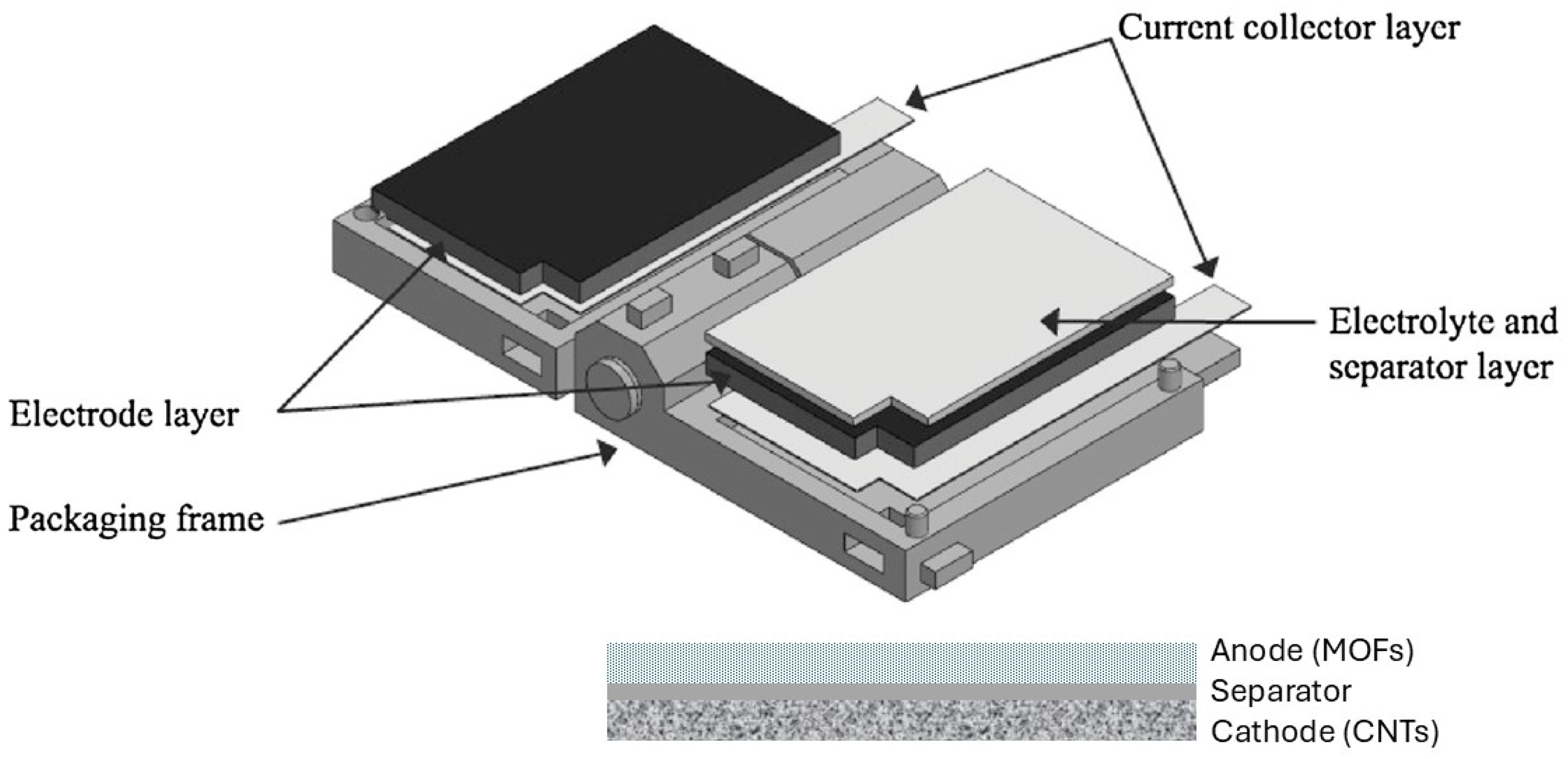
2.4. Experimental Setup

The experimental setup for the supercapacitor cell was performed according to Ref. [4], with some design modification (see Figure 1).
For this study, a Creality® CR-20 Pro 3D printer was used to create the supercapacitor’s frames. The two halves of the frame were designed as upper and lower parts. The dimensions of each half-frame were 20 mm × 20 mm × 5 mm. Polyethylene terephthalate glycol (PETG) filament purchased from Das Filament (Emskirchen, Germany) was the material that was selected for the 3D printed frames. This is because PETG is a material with great chemical resistance, and for this reason, it was ideal for the experiments, as the frames would not be chemically degraded during the experimental characterization time frame. Moreover, the fabrication of the SC cell followed the same steps as the setup in the first design. The frames had the following layers: stainless steel as current collector, carbon-based electrodes coated on one side with MOF, a viton® flange, cut accordingly in order to avoid a short circuit, and a separator soaked in electrolyte.
The preparation of materials and electrochemical performance measurement were completed using general electrochemical equipment. Electrochemical performance measurements were carried out using a Biologic SP-150 (Seyssinet-Pariset, France) electrochemical workstation and the software package EC-LAB (V11.20).
All the measurements were conducted at room temperature (22 ± 2 °C). In the following, all equations that were used in the evaluation of the supercapacitors are listed and explained below.
The gravimetric specific capacitance ( C s was calculated from the GCD discharge curves using Equations (1) and (2)
C s = I · Δ t m · Δ V  
where I is the current in milliamperes (mA), ∆t is the charging/discharging time (s), m is the total weight of active materials of the two electrodes (g), and Δ V is the voltage of the discharge. In addition, the CV curve was not ideally rectangular, and most of the time, it was a curve without a specific shape. Therefore, in those cases, using the integral in the CV curve was the only way to calculate the capacitance of the SC. Consequently, the equation can be further expressed as the following:
C s = | i | Δ t m Δ V
Furthermore, two other essential attributes of an SC are the power density and the energy density, which should be measured only in a SC cell, as there is no meaning in measuring them in a single electrode.
E g = 1 2 · C s ( Δ V ) 2 3.6
where C s is the specific capacitance in (F/g) and Δ V is the window voltage in ( V ).
Next, the power density P g was calculated by Equation (4):
P g = 3600 E g Δ t    
where E g is the energy density in (Wh/kg) and Δ t the discharging time.

3. Results and Discussion

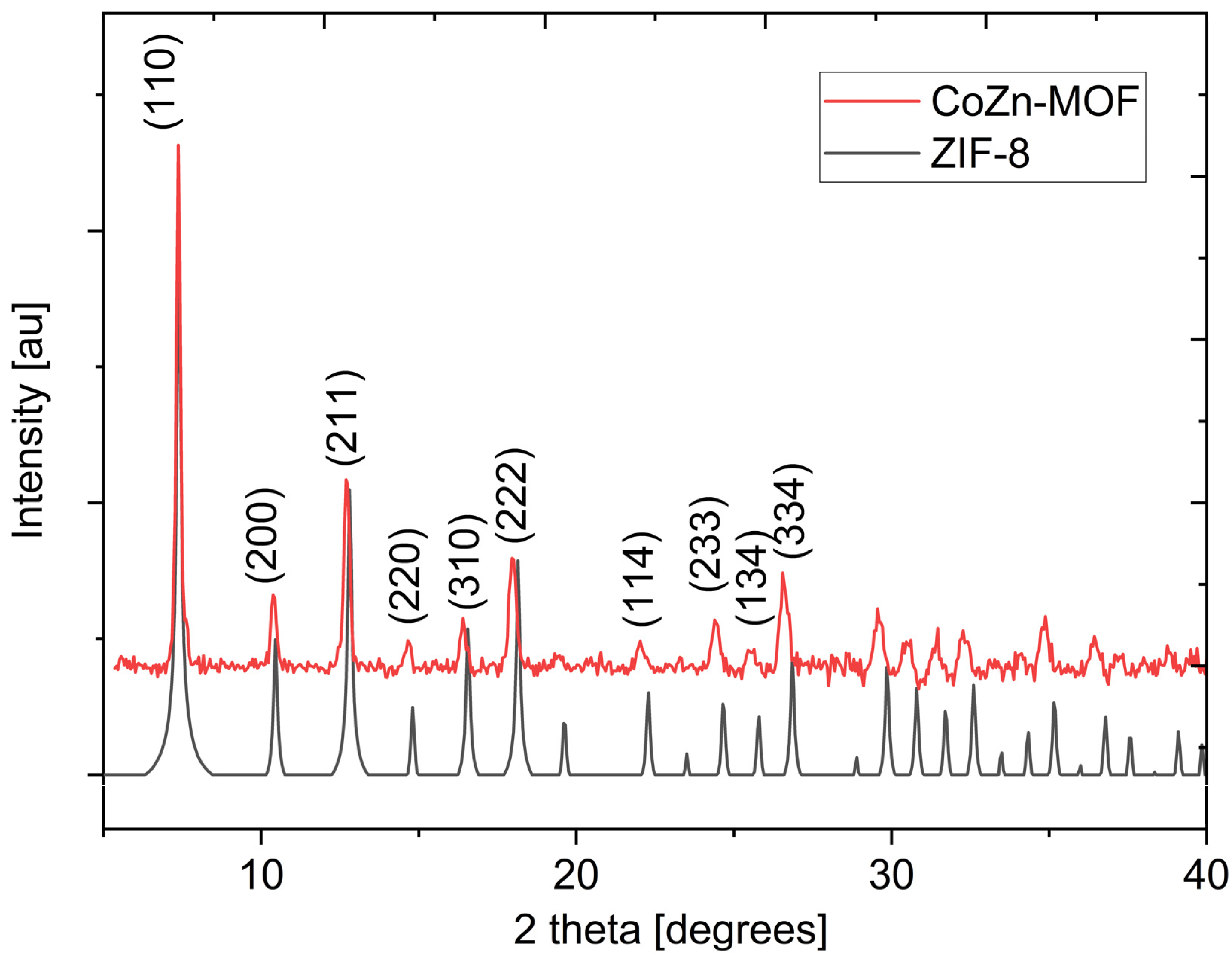
3.1. Characterization

The crystallinity of the synthesized materials was analyzed using X-ray powder diffraction (XRD) on a Bruker D8 Advance diffractometer using a Cu Ka radiation source (1.5406 Å) at 40 kV and 40 mA with a step of 0.05° in 2θ.
The X-ray diffraction (XRD) investigation undertaken in this study gave insights into the crystalline profiles of both ZIF-8 and its CoZn-MOF counterpart, thereby enhancing our understanding of their distinctive structural. The XRD spectra presented in Figure 2 indicate the presence of crystalline phases associated with ZIF-8 and CoZn-MOF. This configuration shows a cubic space group topology for the CoZn-MOF, and that, besides a slight shift to lower values, the crystal structure matches the one of the conventional ZIF-8 framework [48].
Figure 2 reveals the distinct diffraction peaks positioned at 7.4°, 10.5°, and 12.7°, corresponding to the (110), (200), and (211) planes, which are characteristic for ZIF-8 MOFs, being in alignment between observed and simulated data and thus corroborating the consistency of the experimental results with the anticipated structural attributes of ZIF-8 [35,49,50,51].
Figure 2. XRD patterns of CoZn-MOF in comparison with the ZIF-8 as deposited at the Cambridge Crystallographic Data Centre (CCDC 864310) [3] and characteristic (hkl) values compared to [52,53].
Processes 12 02778 g002
In Figure 3 XRD spectra of the pristine and modified MWCNTs are presented. Clearly, the treatment did not induce any dramatic changes in the crystallinity of the MWCNTs.
On the other hand, the Raman spectra presented in Figure 4 and the FT-IR spectra presented in Figure 5 show changes in the surface chemistry of the treated MWCNTs. Raman spectroscopy is a method commonly employed to characterize carbon nanotubes (CNTs) and serves as a crucial tool for the assessment of carbon-based materials, revealing distinct characteristic spectra for sp3, sp2, and sp carbons, in addition to disordered sp2 carbons, fullerenes, and carbon nanotubes (CNTs) [54]. In the high-frequency area of the spectrum, two bands characteristic of carbon nanotubes (CNTs) were observed as the following: the graphite band (G band) and the disorder and defects band (D band). The ratio of the strength of the D band to the G band, denoted as D/G, correlates with the degree of disorder in the nanotube. An elevation in the D/G ratio indicates a greater proportion of sp3 carbon, typically ascribed to an increased occurrence of structural defects [25]. In the present case, the treatment led to an increased number of defects as the D/G ratio increased from 0.338 for the pristine MWCNTs to 0.382 and 0.404 for the acetic acid and nitric acid treatments, respectively.
The large shoulder band in the 2800–3500 cm−1 area in the FT-IR spectra (Figure 5) is ascribed to the presence of hydroxyl and carboxylic groups, as well as residual water in the KBr discs. The peak associated with C=C bonding appears at roughly 1600 cm−1. In general, acid treatment produces a peak near 1475 cm−1, indicative of C–O stretching, signifying the incorporation of carboxylic groups resulting from surface oxidation [54,55].
As can be seen in the TGA and DSC results presented in Figure 6, the oxidized CNTs commenced decomposition earlier than the non-oxidized CNTs, as evidenced by TGA. This is related to the existence of functional groups on the tubes. The results from the TGA analysis indicated strong concordance with the findings from Raman spectroscopy. The early degradation of functionalized CNTs is corroborated by the elevated D/G ratio values (given in Figure 4) for these specimens. The adsorption of functional groups elevates the defect density in a nanotube structure, augmenting the D/G ratio and facilitating the accelerated disintegration of CNTs.

3.2. Electrochemical Measurements

Cyclic voltammograms (CVs) were taken at various scan rates of 5, 20, 50, and 100 mV·s−1 with a potential window of −0.2 to +0.5 V. Electrochemical impedance spectroscopy (EIS) measurements were performed in a frequency range from 10−2 to 2 × 10⁵ Hz and at an amplitude of 5 mV at open circuit potential. Galvanostatic charge–discharge (GCD) tests were carried out at current densities of 0.2, 0.5, and 0.8 A/g with a cutoff voltage range of −0.2 to +0.5 V.
Three experiments were performed with the same cathode (CoZn-MOF) in each experiment so that the main difference between them was the anode. The CNTs which were used for each anode had a different pretreatment. Therefore, there was a comparison between CNTs that were pretreated with nitric acid, CNTs that were pretreated with acetic acid, and finally, CNTs that were unprocessed.
To investigate the supercapacitive performance of CNTs (acetic acid)//CoZn-MOF as electrode material, electrochemical measurements were carried out by using an electrochemical workstation. The capacitive behavior was examined using cyclic voltammetry (CV) as depicted in Figure 7a. The CV curves under different scanning rates, from 5 to 100 mVs−1, presented a nearly rectangular feature, indicating a close-to-ideal electrical double-layered nature of the electrode. The CNT (acetic acid)//CoZn-MOF SC cells exhibited a high specific capacitance of 2.857 Fg−1 at a scan rate of 5 mVs−1, which decreased to 1.428 Fg−1 at a high scan rate of 100 mVs−1. As the scan rate increased, the CV curve deviated quite a bit from ideality. At the limits, there was an exponential increase in the current (rather faradaic actions), while in the area of polarizability, the capacitive current seems to have carried an ohmic component and the curves demonstrated a quite good electrical reversibility. Also, the cathodic peak shifted to the left, which might be attributed to insignificant diffusion of electrolytic ions into electrode material within a limited time. Note that the capacitive contributions from blank carbon fiber paper are negligible [6]. The exact performance rates were further evaluated by galvanostatic charge–discharge (GCD) measurements (see Figure 7b), the charging and discharging curves of different current densities, including 0.2, 0.5, and 0.8 Ag−1. All these curves present a symmetrical feature, suggesting an electric double-layered capacitor nature of fast charge–discharge processes. Accordingly, in a wide potential window of 0.7 V, the specific capacitance could reach 0.57 Fg−1 at a current density of 0.2 Ag−1.
To confirm the pretreatment influence of the CNTs on the supercapacitive properties of the CoZn-MOF material, electrochemical measurements in a two-electrode system using two other CNTs with different pretreatments were carried out. Both the CV and GCD tests of the CNT (unprocessed)//CoZn-MOF with unprocessed CNTs and CNT (nitric acid)//CoZn-MOF with CNTs processed with nitric acid showed much lower capacitances when compared with those of CNT (acetic acid)//CoZn-MOF. The maximum specific capacitance of CNT (unprocessed)//CoZn-MOF at a scan rate of 5 mVs−1 was 1.428 Fg−1 and 0.057 Fg−1 at a current density of 0.2 Ag−1, which decreased to 0.428 Fg−1 at a scan rate of 100 mV/s and to 0.023 Fg−1 at a current density of 0.8 mA, respectively. In addition, the maximum specific capacitances of CNT (nitric acid)//CoZn-MOF at a scan rate of 5 mVs−1 was 1.243 Fg−1 and 0.037 Fg−1 at a current density of 0.2 Ag−1, and it decreased to 0.37 Fg−1 at a scan rate of 100 mV/s and 0.0114 Fg−1 at a current density of 0.8 Ag−1. When the current density increases, the specific capacitance of the symmetrical cell decreases. It is accepted that the capacitance gradually decreases with an increase in current density, which is attributed to the low utilization of active materials under high charge–discharge current densities [39].
The cyclic voltammetry (CV) profiles associated with variation in CNTs exhibited a deviation from the expected rectangular shape typical of an ideal electrical double-layer capacitor. However, it is noteworthy to mention that these CV profiles exhibited a consistent current response at lower scan rates, notably at 5 mVs−1 and 20 mVs−1. Yet, as the scan rate was incrementally increased from 5 mVs−1 to 100 mVs−1, alterations in the shapes of the CV curves became evident (refer to Figure 8a and Figure 9a).
This transition in the CV curve morphology stems from a fundamental cause, namely the constrained interaction time between the active material and the electrolyte. As the scan rate increases, the active material is lacking time for comprehensive interaction with the electrolyte, and thus a reduction in the utilization ratio of the active material itself [5].
Notably, the CV curves corresponding to CNT (unprocessed)//CoZn-MOF (depicted in (a)) and CNT (nitric acid)//CoZn-MOF (illustrated in Figure 9a) manifested a resemblance to that of CNT (acetic acid)//CoZn-MOF. However, these similarities were coupled with relatively diminutive areas that corresponded to modest capacitance levels. This reduction in capacitance can be ascribed to the suboptimal conductivity exhibited by the MOF material, which in turn impeded efficient energy storage and transfer mechanisms.
Figure 7c, Figure 8c and Figure 9c show a typical Nyquist plot from high frequencies (200 kHz) down to 100 mHz at 5 mV. The equivalent circuit used to fit the impedance spectra is presented in the Supplementary Information. Besides resistance and capacitance, the equivalent circuit includes also a Warburg element. The corresponding impedance spectra (Figures S2–S4) along with their fitting parameters can be found in the Supplementary Materials.
In this study, a small semicircle was observed in the higher frequency range because the contact resistance and the charge transfer resistance were low. The value of R, at high frequencies, seems very small. This may indicate that the solution resistance and material resistance were small. The semicircle at high frequences had a diameter of 150–200 ohms depending on the CNT pretreatment method. At low frequencies, the impedances were similar to each other while the slopes were steeper than 45°, indicating diffusion limitation but not pure Warburg diffusion. The CNT (unprocessed)//CoZn-MOF displayed a smaller semicircle at high frequencies than the others, which illustrated that the kinetic performance of the material was improved. Moreover, this symmetrical device of CNT (acetic acid)//CoZn-MOF exhibited an energy density of 0.015 Wh/kg at a power density of 26.48 W/kg. It should be noted that CNT (unprocessed)//CoZn-MOF and CNT (nitric acid)//CoZn-MOF had significantly lower energy density.
These experimental results bring to the forefront a conspicuous and noteworthy enhancement in specific capacitance values within the realm of carbon nanotubes (CNTs) after their meticulous treatment with acetic acid. Remarkably, the specific capacitance values calculated based on the CV measurements soared to 2.857 F/g when subjected to a scan rate of 5 mV/s. This outcome not only underscores the potency of the acetic acid treatment but also accentuates its endurance in the face of more demanding operational conditions, where a commendable specific capacitance of 0.57 F/g was attained under a considerably higher current density of 0.2 A/g. The results of the specific capacity, energy, and power densities based on galvanostatic charge–discharge (GCD) measurements are tabulated in Table S1 in the Supplementary Materials.
Intriguingly, these observed outcomes introduce a paradoxical element as the untreated CNTs unexpectedly outshined their counterparts subjected to nitric acid pretreatment in terms of specific capacitance levels. This unexpected divergence in performance warrants a deeper analytical exploration into the underlying mechanisms that orchestrate the interaction between diverse pretreatment strategies and the supercapacitive behavior exhibited by CNTs.
This study’s thorough analysis of these complex relationships highlights the challenges in optimizing energy storage solutions and establishes a basis for strategic approaches to utilizing the interactions among materials, treatments, and performance standards. By doing so, it enhances the expanding field of supercapacitor technology and facilitates the development of advanced energy storage devices.

4. Conclusions

The undertaken study successfully achieved the synthesis of CoZn-MOF through a straightforward hydrothermal approach. The characterization of the fabricated materials was conducted using X-ray diffraction (XRD), affording a comprehensive understanding of their structure and composition. Subsequently, carbon nanotubes (CNTs) were subjected to three distinct pretreatment methods before being harnessed as an anode in a supercapacitor (SC) configuration, with CoZn-MOF serving as the cathode.
Remarkably, among the pretreatment techniques, the CNTs treated with acetic acid exhibited the most promising electrochemical performance. This outcome was substantiated by the exceptional attributes demonstrated by the CNT (acetic acid)//CoZn-MOF cell. At a scan rate of 5 mV/s, this cell achieved a specific capacitance of 2.857 F/g. Under a current density of 0.2 A/g, a capacitance of 0.57 F/g was realized.
Furthermore, based on the GCD measurements, the energy storage capabilities of the CNT (acetic acid)//CoZn-MOF device resulted in an energy density of 0.015 Wh/kg at a power density of 26.48 W/kg. It is essential to point out that comparative investigations involving CNT (unprocessed)//CoZn-MOF and CNT (nitric acid)//CoZn-MOF demonstrated notably lower energy densities and specific capacitances. This contrast underscores the significant impact of CNT pretreatment on supercapacitor performance outcomes.
From the performed CV measurements, it is obvious that the used materials exhibited capacitive properties in the potential range of −0.2 to 0.5 V, resulting in specific capacities of 0.57 to 2.857 F/g. Compared to state-of-the-art materials used in supercapacitors, these values are moderate. Nevertheless, improvement in this specific area can increase the specific capacitance. This challenging concept will be addressed in future work.
This study’s findings demonstrate the crucial significance of CNTs in providing numerous active sites that support increased capacitance levels. Furthermore, it was observed that CNT pretreatment had a dual function by improving conductivity and promoting the formation of efficient ion transport channels. The complex interaction between CNTs and CoZn-MOF, as evidenced by the unique electrochemical results of the different pretreatment techniques, underscores the diverse aspects of enhancing supercapacitor performance. These findings enhance the field of energy storage advancements, highlighting the significance of customized material interactions and pretreatment techniques in advancing energy storage technologies.

Supplementary Materials

The following supporting information can be downloaded at: https://www.mdpi.com/article/10.3390/pr12122778/s1, Figure S1: Equivalent circuit used to fit the impedance spectroscopy measurements. Figure S2: Nyquist impedance plot of the CNT//CoZn-MOF-2 (CNTs pretreatment: acetic acid) cell. Figure S3: Nyquist impedance plot of the CNT//CoZn-MOF-2 (CNTs pretreatment: nitric acid) cell. Figure S4: Nyquist impedance plot of the CNT//CoZn-MOF-2 (CNTs pretreatment: unprocessed) cell. Table S1: Specific capacities, energy, and power densities of the cells in this study at V = 0.7 [V] and 0.8 [mA] from galvanostatic charge-discharge measurements (GCD) measurements.

Author Contributions

Conceptualization, C.A. (Christos Argirusis); methodology, C.A. (Christos Argirusis); validation, C.A. (Christina Angelara), C.A. (Christos Argirusis) and A.K.; formal analysis, C.A. (Christina Angelara) and A.K.; investigation, C.A. (Christina Angelara); resources, G.S. and N.A.; data curation, C.A. (Christina Angelara) and C.A. (Christos Argirusis); writing—original draft preparation, C.A. (Christina Angelara); writing—review and editing, C.A. (Christos Argirusis), A.K., G.S., N.A. and P.P.P.; visualization, C.A. (Christina Angelara); supervision, C.A. (Christos Argirusis); project administration, C.A. (Christos Argirusis), N.A. and P.P.P. All authors have read and agreed to the published version of the manuscript.

Funding

This research received no external funding.

Data Availability Statement

The data presented in this study are available on request from the corresponding author. The data are not publicly available due to privacy as this study in the frame of different theses is not yet finished. Part of the data are included in the figures in this manuscript.

Acknowledgments

We are indebted to Anan Tanwilaisiri for providing us with the design details of his supercapacitor test cell. We thank Christos Vaitsis for his valuable comments on the MOF preparation methods.

Conflicts of Interest

Author Nikolaos Argirusis was employed by the mat4nrg GmbH. The remaining authors declare that the research was conducted in the absence of any commercial or financial relationships that could be construed as a potential conflict of interest.

References

  1. Dutta, A.; Mitra, S.; Basak, M.; Banerjee, T. A comprehensive review on batteries and supercapacitors: Development and challenges since their inception. Energy Storage 2023, 5, e339. [Google Scholar] [CrossRef]
  2. Dubal, D.P.; Chodankar, N.R.; Gomez-Romero, P.; Kim, D.-H. Fundamentals of binary metal oxide-based supercapacitors. In Metal Oxides in Supercapacitors; Dubal, D.P., Gomez-Romero, P., Eds.; Elsevier: Amsterdam, The Netherlands, 2017; pp. 79–98. [Google Scholar]
  3. Jalal, N.I.; Ibrahim, R.I.; Oudah, M.K. A review on Supercapacitors: Types and components. J. Phys. Conf. Ser. 2021, 1973, 012015. [Google Scholar] [CrossRef]
  4. Liu, X.; Sun, Y.; Tong, Y.; Wang, X.; Zheng, J.; Wu, Y.; Li, H.; Niu, L.; Hou, Y. Exploration in materials, electrolytes and performance towards metal ion (Li, Na, K, Zn and Mg)-based hybrid capacitors: A review. Nano Energy 2021, 86, 106070. [Google Scholar] [CrossRef]
  5. Tanwilaisiri, A. Design and Fabrication of Supercapacitors. PhD Thesis, Design and Physical Science, Department of Design, College of Engineering, Brunel University, London, UK, 2018. [Google Scholar]
  6. Simon, P.; Gogotsi, Y. Materials for electrochemical capacitors. Nat. Mater. 2008, 7, 845–854. [Google Scholar] [CrossRef] [PubMed]
  7. Iqbal, M.Z.; Faisal, M.M.; Ali, S.R. Integration of supercapacitors and batteries towards high-performance hybrid energy storage devices. Int. J. Energy Res. 2021, 45, 1449–1479. [Google Scholar] [CrossRef]
  8. Park, K.; Zheng, N.; Côté, A.; Choi, J.; Huang, R.; Uribe-Romo, F.; Chae, H.; O’Keeffe, M.; Yaghi, O. Exceptional Chemical and Thermal Stability of Zeolitic Imidazolate Frameworks. Proc. Natl. Acad. Sci. USA 2006, 103, 10186–10191. [Google Scholar] [CrossRef]
  9. Wang, L.; Wang, C.; Wang, H.; Jiao, X.; Ouyang, Y.; Xia, X.; Lei, W.; Hao, Q. ZIF-8 nanocrystals derived N-doped carbon decorated graphene sheets for symmetric supercapacitors. Electrochim. Acta 2018, 289, 494–502. [Google Scholar] [CrossRef]
  10. Chatterjee, D.P.; Nandi, A.K. A review on the recent advances in hybrid supercapacitors. J. Mater. Chem. A Mater. 2021, 9, 15880–15918. [Google Scholar] [CrossRef]
  11. Minakshi, M.; Samayamanthry, A.; Whale, J.; Aughterson, R.; Shinde, P.A.; Ariga, K.; Shrestha, L.K. Phosphorous—Containing Activated Carbon Derived from Natural Honeydew Peel Powers Aqueous Supercapacitors. Chem. Asian J. 2024, 19, e202400622. [Google Scholar] [CrossRef]
  12. Minakshi, M.; Mujeeb, A.; Whale, J.; Evans, R.; Aughterson, R.; Shinde, P.A.; Ariga, K.; Shrestha Kumar, L. Synthesis of Porous Carbon Honeycomb Structures Derived from Hemp for Hybrid Supercapacitors with Improved Electrochemistry. ChemPlusChem 2024, e202400408. [Google Scholar] [CrossRef]
  13. Liang, Y.; Yao, W.; Duan, J.; Chu, M.; Sun, S.; Li, X. Nickel cobalt bimetallic metal-organic frameworks with a layer-and-channel structure for high-performance supercapacitors. J. Energy Storage 2021, 33, 102149. [Google Scholar] [CrossRef]
  14. Brousse, T.; Comte, A.L.; Bélanger, D. To be or not to be pseudocapacitive. J. Electrochem. Soc. 2014, 162, A5185–A5189. [Google Scholar] [CrossRef]
  15. Zhao, J.; Burke, A.F. Electrochemical capacitors: Materials, technologies and performance. Energy Storage Mater. 2021, 36, 31–55. [Google Scholar] [CrossRef]
  16. Gonzalez, A.; Goikolea, E.; Barrena, J.A.; Mysyk, R. Review on supercapacitors: Technologies and materials. Renew. Sustain. Energy Rev. 2016, 58, 1189–1206. [Google Scholar] [CrossRef]
  17. Sundriyal, S.; Kaur, H.; Bhardwaj, S.; Kumar, B.; Mishra, S.; Kim, K.; Deep, A. Metal-organic frameworks and their composites as efficient electrodes for supercapacitor applications. Coord. Chem. Rev. 2018, 369, 15–38. [Google Scholar] [CrossRef]
  18. Vaitsis, C.; Mechili, M.; Argirusis, N.; Kanellou, E.; Pandis, P.; Sourkouni, G.; Zorpas, A.; Argirusis, C. Ultrasound-assisted preparation methods of nanoparticles for energy related applications. In Nanotechnology and the Environment; IntechOpen: London, UK, 2020. [Google Scholar] [CrossRef]
  19. Chen, D.; Wei, L.; Li, J.; Wu, Q. Nanoporous materials derived from metal-organic framework for supercapacitor application. J. Energy Storage 2020, 31, 101525. [Google Scholar] [CrossRef]
  20. Vangari, M.; Pryor, T.; Li, J. Supercapacitors: Review of materials and fabrication methods. J. Energy Eng. 2013, 139, 72–79. [Google Scholar] [CrossRef]
  21. Zhong, C.; Duan, Y.; Cao, X.; Yang, W.; Wu, X.; Xia, X.; Fan, Z. A review of electrolyte materials and compositions for electrochemical supercapacitors. Chem. Soc. Rev. 2015, 44, 7484–7539. [Google Scholar] [CrossRef]
  22. Kaempgen, M.; Chan, C.K.; Ma, J.; Cui, Y.; Gruner, G. Printable thin film supercapacitors using single-walled carbon nanotubes. Nano Lett. 2009, 9, 1872–1876. [Google Scholar] [CrossRef]
  23. Vaitsis, C.; Sourkouni, G.; Argirusis, C. Sonochemical Synthesis of MOFs. In Metal-Organic Frameworks for Biomedical Applications; Mozafari, M., Ed.; Woodhead Publishing: Sawston, UK, 2020; pp. 223–244. [Google Scholar] [CrossRef]
  24. Yin, Z.; Wan, S.; Yang, J.; Kurmoo, M.; Zeng, M.-H. Recent advances in post-synthetic modification of metal–organic frameworks: New types and tandem reactions. Coord. Chem. Rev. 2019, 378, 500–512. [Google Scholar] [CrossRef]
  25. Rubio-Martinez, M.; Avci-Camur, C.; Thornton, A.W.; Imaz, I.; Maspoch, D.; Hill, M.R. New synthetic routes towards MOF production at scale. Chem. Soc. Rev. 2017, 46, 3453–3480. [Google Scholar] [CrossRef] [PubMed]
  26. Li, C.; Sun, X.; Yao, Y.; Hong, G. Recent advances of electrically conductive metal-organic frameworks in electrochemical applications. Mater. Today Nano 2021, 13, 100105. [Google Scholar] [CrossRef]
  27. Vaitsis, C.; Kanellou, E.; Angelara, C.; Pandis, P.; Argirusis, N.; Sourkouni, G.; Zorpas, A.; Karantonis, A.; Argirusis, C. Chapter 18—MOFs–metal oxides/sulfides/phosphides nanocomposites for supercapacitors. In Metal-Organic Framework-Based Nanomaterials for Energy Conversion and Storage; Nguyen, T.A., Ram, G.Y., Gupta, K., Eds.; Elsevier: Amsterdam, The Netherlands, 2022; pp. 393–412. [Google Scholar]
  28. Osorio, A.G.; Silveira, I.C.L.; Bueno, V.L.; Begmann, C.P. H2SO4/HNO3/HCl—Functionalization and its effect on dispersion of carbon nanotubes in aqueous media. Appl. Surf. Sci. 2008, 255, 2485–2489. [Google Scholar] [CrossRef]
  29. Saraf, M.; Natarajan, K.; Mobin, S.M. Robust nanocomposite of nitrogen-doped reduced graphene oxide and MnO2 nanorods for high-performance supercapacitors and nonenzymatic peroxide sensors. ACS Sustain. Chem. Eng. 2018, 6, 10489–10504. [Google Scholar] [CrossRef]
  30. Platek, A.; Nita, C.; Ghimbeu, C.M.; Frąckowiak, E.; Fic, K. Electrochemical capacitors operating in aqueous electrolyte with volumetric characteristics improved by sustainable templating of electrode materials. Electrochim. Acta 2020, 338, 135788. [Google Scholar] [CrossRef]
  31. Raymundo-Pinero, E.; Kierzek, K.; Machnikowski, J.; Béguin, F. Relationship between the nanoporous texture of activated carbons and their capacitance properties in different electrolytes. Carbon 2006, 44, 2498–2507. [Google Scholar] [CrossRef]
  32. Nordin, A.; Ismail, A.F.; Misdan, N.; Mohd Nazri, N.A. Modified ZIF-8 mixed matrix membrane for CO2/CH4 separation. AIP Conf. Proc. 2017, 1891, 020091. [Google Scholar] [CrossRef]
  33. Zhang, Y.; Lin, B.; Sun, Y.; Zhang, X.; Yang, H.; Wang, J. Carbon nanotubes@metal–organic frameworks as Mn-based symmetrical supercapacitor electrodes for enhanced charge storage. RSC Adv. 2015, 5, 58100–58106. [Google Scholar] [CrossRef]
  34. Wu, S.; Liu, J.; Wang, H.; Yan, H. A review of performance optimization of MOF-derived metal oxide as electrode materials for supercapacitors. Int. J. Energy Res. 2019, 43, 697–716. [Google Scholar] [CrossRef]
  35. Vaitsis, C.; Sourkouni, G.; Argirusis, C. Metal Organic Frameworks (MOFs) and ultrasound: A review. Ultrason. Sonochemistry 2019, 52, 106–119. [Google Scholar] [CrossRef]
  36. Xu, B.; Zhang, H.; Mei, H.; Sun, D. Recent progress in metal-organic framework-based supercapacitor electrode materials. Coord. Chem. Rev. 2020, 420, 213438. [Google Scholar] [CrossRef]
  37. Stock, N.; Biswas, S. Synthesis of Metal-Organic Frameworks (MOFs)—Routes to Various MOF Topologies, Morphologies, and Composites. Chem. Rev. 2012, 112, 933–969. [Google Scholar] [CrossRef] [PubMed]
  38. Zhang, W.-X.; Liao, P.-Q.; Lin, R.-B.; Wei, Y.-S.; Zeng, M.-H.; Chen, X.-M. Metal cluster-based functional porous coordination polymers. Coord. Chem. Rev. 2015, 293–318, 263–278. [Google Scholar] [CrossRef]
  39. Bigdeli, F.; Ghasempour, H.; Tehrani, A.; Morsali, A.; Hosseini-Monfared, H. Ultrasound-assisted synthesis of nano-structured Zinc(II)-based metal-organic frameworks as precursors for the synthesis of ZnO nano-structures. Ultrason. Sonochemistry 2017, 37, 29–36. [Google Scholar] [CrossRef]
  40. Abuzalat, O.; Wong, D.; Elayed, M.; Park, S.; Kim, S. Sonochemical fabrication of Cu(II) and Zn(II) metal-organic framework films on metal substrates. Ultrason. Sonochemistry 2018, 45, 180–188. [Google Scholar] [CrossRef]
  41. Schneuwly, A.; Gallay, R. Properties and applications of supercapacitors from the state-of-the-art to future trends. In Proceedings of the PCIM 2000 Europe, Nuremberg, Germany, 6–8 June 2000; pp. 1–10. [Google Scholar]
  42. Neisi, Z.; Ansari-Asl, Z.; Dezfuli, A.S. Polyaniline/Cu(II) Metal-Organic Frameworks Composite for High Performance Supercapacitor Electrode. J. Inorg. Organomet. Polym. 2019, 29, 1838–1847. [Google Scholar] [CrossRef]
  43. Sharma, S.; Chand, P. Supercapacitor and electrochemical techniques: A brief review. Results Chem. 2023, 5, 100885. [Google Scholar] [CrossRef]
  44. Tanwilaisiri, A.; Xu, Y.; Zhang, R.; Harrison, D.; Fyson, J.; Areir, M. Design and fabrication of modular supercapacitors using 3D printing. J. Energy Storage 2018, 16, 1–7. [Google Scholar] [CrossRef]
  45. Halper, M.S.; Ellenbogen, J.C. Supercapacitors: A Brief Overview. The MITRE Corporation, March 2006, pp. 1–34. Available online: https://www.mitre.org/sites/default/files/pdf/06_0667.pdf (accessed on 9 April 2024).
  46. Chen, Z.; Wang, D.; Chua, D.; Poh, C.K.; Chen, P.; Lin, J.; Lou, D.; Chen, L.; Wu, Y. High-performance supercapacitors based on hierarchically porous graphite particles. Adv. Energy Mater. 2011, 1, 551–556. [Google Scholar] [CrossRef]
  47. Hen, J.; Li, W.; Wang, D.; Yang, S.; Wen, J. Electrochemical characterization of carbon nanotubes as electrode in electrochemical double-layer capacitors. Carbon 2022, 40, 1193–1197. [Google Scholar] [CrossRef]
  48. Pachfule, P.; Das, R.; Poddar, P.; Banerjee, R. Solvothermal Synthesis, Structure, and Properties of Metal Organic Framework Isomers Derived from a Partially Fluorinated Link. Chem. Mater. 2011, 23, 1215–1222. [Google Scholar] [CrossRef]
  49. Forster, P.M.; Stock, N.; Cheetham, A. A high-throughput investigation of the role of pH, temperature, concentration, and time on the synthesis of hybrid inorganic-organic materials. Chem. Commun. 2005, 44, 7608–7611. [Google Scholar] [CrossRef] [PubMed]
  50. Cravillon, J.; Nayuk, R.; Springer, S.; Feldhoff, A.; Huber, K.; Wiebcke, M. Rapid Room-Temperature Synthesis and Characterization of Nanocrystals of a Prototypical Zeolitic Imidazolate Framework. Chem. Mater. 2009, 21, 1410–1412. [Google Scholar] [CrossRef]
  51. Kim, B.K.; Sy, S.; Yu, A.; Zhang, J. Electrochemical supercapacitors for energy storage and conversion. In Handbook of Clean Energy Systems; John Wiley & Sons: Hoboken, NJ, USA, 2015; pp. 1–25. [Google Scholar] [CrossRef]
  52. Thanh, M.T.; Thien, T.V.; Chau, V.T.T.; Du, P.D.; Hung, N.P.; Khieu, D.Q. Synthesis of Iron Doped Zeolite Imidazolate Framework-8 and Its Remazol Deep Black RGB Dye Adsorption Ability. J. Chem. 2017, 1–18. [Google Scholar] [CrossRef]
  53. Nik Abdul Hadi, M. Nordin; Ahmad Fauzi Ismail; Noorhana Yahya, Zeolitic imidazole framework 8 decorated graphene oxide (ZIF-8/GO) mixed matrix membrane (MMM) for CO2/CH4 separation. J. Teknol. 2017, 2017, 5045973. [Google Scholar] [CrossRef]
  54. Dresselhaus, M.; Jorio, A.; Filho, A.S.; Dresselhaus, G.; Saito, R. Raman spectroscopy on one isolated carbon nanotube. Phys. B 2002, 323, 15–20. [Google Scholar] [CrossRef]
  55. Socrates, G. Infrared Characteristic Group Frequencies: Tables and Charts, 2nd ed.; John Wiley & Sons: Chichester, UK, 1994. [Google Scholar]
Figure 1. Schematic of the modified design of the supercapacitor testing frame with a cross-section of the cell at the bottom indicating the materials used in the cells. Obtained from Ref. [44] with permission. Copyright Elsevier.
Processes 12 02778 g001
Figure 3. XRD spectra of the pristine and chemically treated MWCNTs.
Processes 12 02778 g003
Figure 4. Raman spectra of the pristine and chemically modified MWCNTs.
Processes 12 02778 g004
Figure 5. FT-IR spectra of the pristine and chemically modified MWCNTs.
Processes 12 02778 g005
Figure 6. TGA (left) and DTA (right) results of the used MWCNTs.
Processes 12 02778 g006
Figure 7. Electrochemical performance of the CNT (acetic acid)//CoZn-MOF cell: (a) CV curves at different scan rates; (b) GCD curves at different currents; (c) Nyquist plot for a frequency range between 200 kHz and 100 mHz.
Processes 12 02778 g007
Figure 8. Electrochemical performance of the CNT//CoZn-MOF (CNT pretreatment: unprocessed) cell: (a) CV curves at different scan rates; (b) GCD curves at different current densities; (c) Nyquist plot for a frequency range between 200 kHz and 100 mHz.
Processes 12 02778 g008
Figure 9. Electrochemical performance of the CNT//CoZn-MOF (CNT pretreatment: nitric acid) cell: (a) CV curves at different scan rates; (b) GCD curves at different current densities; (c) Nyquist plot for a frequency range between 200 kHz and 100 mHz.
Processes 12 02778 g009
Disclaimer/Publisher’s Note: The statements, opinions and data contained in all publications are solely those of the individual author(s) and contributor(s) and not of MDPI and/or the editor(s). MDPI and/or the editor(s) disclaim responsibility for any injury to people or property resulting from any ideas, methods, instructions or products referred to in the content.

