Article

A Novel Approach to DBS Electrode Prototyping

by
Jesús Eduardo Medina-Rodríguez
1,
Armando Josue Piña-Díaz
1,
Juan Alejandro Flores-Campos
2,
Karla Nayeli Silva-Garces
1,
Armando Oropeza-Osornio
3 and
Christopher René Torres San Miguel
1,*
1
Instituto Politécnico Nacional, Escuela Superior de Ingeniería Mecánica y Eléctrica, Unidad Zacatenco, Sección de Estudios de Posgrado e Investigación, Unidad Zacatenco, Mexico City 07738, Mexico
2
Instituto Politécnico Nacional, Unidad Profesional Interdisciplinaria en Ingeniería y Tecnologías Avanzadas, Mexico City 07340, Mexico
3
Instituto Politécnico Nacional, Escuela Superior de Ingeniería Mecánica y Eléctrica, Unidad Ticomán, Mexico City 07340, Mexico
*
Author to whom correspondence should be addressed.
Processes 2024, 12(12), 2694; https://doi.org/10.3390/pr12122694
Submission received: 3 October 2024 / Revised: 11 November 2024 / Accepted: 16 November 2024 / Published: 29 November 2024

Abstract

:
This research project focuses on the design and fabrication of a deep brain stimulation (DBS) electrode used for Parkinson’s disease. It is a combination of technologies, such as 3D printing injection of polymers and silicones at high and low temperatures, used to develop a manufacturing process of a DBS electrode prototype. For the manufacturing process of the DBS electrode, two case studies are proposed, one at high temperature and the other at room temperature. Rings are used for communication at the ends with the deep brain stimulation (DBS). For the development, different types of molds and nozzles were proposed, considering various variables to control the material flow since polymers or copolymers melted at high temperatures behave differently from silicones injected at room temperature. The injection of Polyamide as a coating for a silver core in a mold, as well as the injection of silicone over a steel core, have been applied theoretically and experimentally. The results show a new method and technique to produce DBS electrodes at a low cost.

1. Introduction

This study focuses on the implementation of Deep Brain Stimulation (DBS) devices to treat Parkinson’s disease (PD). This neurological disorder affects both the motor and non-motor functions of the human body, with an estimated prevalence of 8.5 million cases of PD and an increase of 81% since 2000. It causes 329,000 deaths, an increase of over 100% since 2000 [1]. Deep brain stimulation emerges as a prominent therapeutic modality, involving the insertion of electrodes into specific areas of the brain to mitigate symptoms associated with Parkinson’s disease by generating electrical impulses [2,3,4]. Enhancing the functioning of brain cells related to motor control is crucial, necessitating the development of techniques and manufacturing processes for deep brain stimulation (DBS) electrodes [5]. Deep brain stimulation electrodes are commonly manufactured using conductive materials coated with biocompatible, non-conductive substances, such as metal alloys, platinum, and iridium, among others [6]. Additionally, a wide range of materials is employed for cable insulation, such as Nylon and cross-linked polyethylene (XLPE), which offer suitable mechanical and electrical insulation properties [7]. In the fabrication of DBS electrodes, polyethylene resins, and other efficient materials are also used to expedite the coating process [8]. The fundamental objective of the conducted research is focused on the manufacturing process or processes of a deep brain stimulation electrode and its manufacturing method. The aim is to comprehend the different coating techniques on a conductive core of high biocompatibility materials and analyze their post-coating behavior and performance. It is also emphasized that, within the plastics industry, there exists a wide range of manufacturing processes for the conductive core and its respective coating, highlighting the importance of experimental research in this field [9]. The plastics industry offers processes such as injection molding, which facilitates the manufacturing of products at low cost, with the ease of obtaining simple cyclic injections of fundamental stages that include work on complex geometries and shapes [10,11]. This includes stages such as plasticization and dosing, injection, final compression, cooling, and, finally, demolding and ejection [12]. Therefore, within a proper polymer injection process, it is sought to ensure that the configuration is suitable for the feeding system that goes into the design of a nozzle and a mold that allows obtaining high injection quality and precision in molding [13]. The versatility of plastic materials in the manufacturing of deep brain stimulation electrodes is highlighted, encompassing silicones, polyethylenes, polyurethanes, and polyureas, among others [14]. The diversity in raw materials allows adaptation to individual needs and biological reactions, ensuring the safety and efficacy of the treatment, as well as the extensive technological development that has enabled remote monitoring of the DBS device. This facilitates the continuous monitoring of the programmed impulses in the deep brain stimulation devices, where the patient has a programmer to adjust and regulate such impulses received and emitted by the DBS electrode as needed [15]. The experimental process aims to comprehend and analyze the results from conceptual design to the manufacturing of DBS electrodes, utilizing various injection techniques and materials, considering the durability of the material and the insertion time of the DBS electrode into the brain [16]. The development of DBS devices has a significant impact on the quality of life of patients in the early stages of the disease. Therefore, computational models have been developed to predict the reaction of treatment with DBS devices in specific areas of brain tissue [17,18].
This research addresses a gap in the field of DBS electrode fabrication using 3D printing and injection molding. The methodology uses molds for high-temperature injection and cold-temperature injection. The focus is on the manufacturing processes of DBS electrodes.

2. Materials and Methods

The relationship between the electrode and brain tissue is a crucial consideration for designing biomechanical models focused on the development of components and medical devices. The DBS electrode is analyzed in terms of its geometry and mechanical properties for implantation. For the manufacturing process of the DBS electrode, two case studies are proposed, one at high temperature and the other at room temperature. Rings are used for communication at the ends with the deep brain stimulation (DBS) device. Both the geometry and composition of the electrode can be observed in Figure 1, where the electrode has a cylindrical shape with a diameter of 2 mm and a length of 300 mm. The development of different types of molds and nozzles considers various variables to control the material flow since polymers or copolymers melted at high temperatures behave differently from silicones injected at room temperature. Polyamide has injection temperatures of 230 to 310 °C. It is advisable to work at high temperatures once the cooling has been taken into account.
Working at high temperatures results in good fluidity, glossy surfaces, few stress cracks, and low shrinkage so that cooling will last a long time.
Silicones injected at room temperature have a viscous consistency, so they change the injection direction by being parallel to the mold location and in a vertical state [19]. Therefore, the viscosity of the material, injection speed, mold type, and nozzle type differ for each process.
To obtain a DBS electrode, the design of a mold is required for each case study. The development of a mold is proposed using both 3D printing and machining by electroerosion for the injection of hot and cold-casting raw materials. The mold design is based on the material selection, the shape of the electrode, and its assembly with the equipment. The construction of the mold and nozzle must align with these three specific aspects. Typically, it is necessary to calculate the mold according to the distance the material travels and the average pressure of the injection equipment. Mold calculation involves the use of charts with parameters for injection molds, which can be seen in Figure 2, serving as guides for design; alternatively, a mold can be calculated using failure theory and thin or thick-walled cylinder theories.
The graph in Figure 2 consists of two important sections: the material flow on the Y-axis and the appropriate pressure for each material group on the X-axis, represented by material groups in sections A, B, and C. The sections for selecting various materials are located at the separation of the groups in the upper right part. Once the material and the length that the material will travel, including the path in the distribution channel, the constriction channel, and the overflow, are identified, the most suitable wall thickness and its respective injection pressure can be obtained.
The materials for injecting the DBS electrode, including its conductive core and communication rings for the hot casting case study, are as follows.
  • Polyamide 6 or 12: Used for injection of low viscosity, this material is one of the most used in the field of implantable medical devices
  • Silver thread: Conductive core of the Electrode with a diameter of 0.213 mm (35 gauge), measuring 300 mm in length. A total of six threads will be used.
  • Silver rings: These rings serve as connections to the cable. Five rings are required at one end and three at the other, soldered to the cables. They have a thickness of 0.2 mm and a width of 8 mm.
For the case study of cold casting injection, the following materials are used:
  • Silicon Eco Flex 0030: Type of platinum-catalyzed silicone, cured at room temperature, low viscosity, super soft, hypoallergenic
  • Stainless steel wire: Conductive core of the electrode with a diameter of 0.2 mm, measuring 300 mm in length. A total of eight wires will be used.
  • Stainless steel rings: These rings serve as connections to the cable. Five rings are required at one end and three at the other, soldered to the cables. They have a thickness of 0.2 mm and a width of 8 mm.

2.1. High-Temperature Mold Calculations

For the case study of high-temperature injection, a calculated mold can be proposed according to the parameters of high-temperature mold design or hot casting, considering the material flow and pressure for injection of Polyamide (PA), which ensures that the force exerted when opening the mold is not greater than the closing pressure. This force is exerted on the sum of the projected surface areas of the cavities, which, in this case, is one, and the filling channels (considered as a single channel). If this pressure exceeds the closing pressure, the molten material may escape between the mold parting planes, causing burrs on the final piece. According to Figure 2, the mold calculation for industrial and commercial equipment is worth mentioning, as the Polyamide used is injected at relatively low pressures. It is a type of Polyamide designed for high-flow and low-viscosity biocompatible 3D printing, as shown in Table 1.
According to the data provided in Table 1 and Figure 2, a mold with a 3 mm wall thickness can be designed for injection using industrial-grade equipment.
For the design of a mold under the criterion of applying failure theories for ductile failures in cylinders designed under the thick or thin wall criterion, the conceptualization of the mold and the free body diagram expressed in Figure 3 is proposed. Here, the application of external and internal pressure can be observed, where the particle representing radial and tangential stresses must be formulated, as shown in Figure 3. It is worth mentioning that it is a state of two principal stresses. This is because the longitudinal stress is negligible since it is an open mold, and the shear stress is because the failure in the mold lies in its deformation, as shown in Table 2. Before a possible rupture, the mold tends to open, rendering it non-functional due to injected material leakage.
The external pressure is 15% greater than the internal pressure, and an internal radius of 0.001 m and an external radius of 0.01 m is proposed, the mold is considered open, so the longitudinal stress is considered equal to 0. The material selected for the first mold prototype is aluminum 7075, with yield strength in the range of 434–503 MPa, so the material limit is far from a possible failure. According to the above, the following CAD model is presented in Figure 4.

2.2. Injection Mold Calculations at Room Temperature

The design of a 3D-printed mold necessitates the application of failure theories in conjunction with either thick-walled or thin-walled vessel theories. The determination of which vessel theory is applicable hinges on the ratio between the mold’s diameter and its wall thickness. If it is less than 20, the theory of thick-walled vessels is applied; if it is greater than 20, the theory of thin-walled vessels is considered [18].
For this case, an internal diameter of 2 mm and an external diameter of 15.60 mm were considered, resulting in a wall thickness of 6.8 mm. According to the theory of thick-walled cylinders, the ratio of diameter to thickness (d/t) should yield a result of less than 20. If it is greater than 20, the theory of thin-walled cylinders is applied. In this case, the ratio yields a result of 2.29, so the application of the theory of thick-walled vessels is correct for the mold design.
Based on this, the free-body diagram of the mold is formulated under this criterion, as shown in Figure 5. It is worth mentioning that the radial stress for the design of this mold is of utmost importance due to the orientation of the overlapping layers and their adhesion between them, which are directly affected by this stress. Therefore, printing orientation is considered for parts manufactured by additive manufacturing.
The design of this mold focuses on calculating the interlayer adhesion force for mold failure.
The internal pressure is given by silicone injection equipment operating at 80 PSI or 0.551 MPa. The external pressure must be 15% greater than the internal pressure, which will be equivalent to the clamping force that the system exerts on the mold.
Table 3 shows the application of the theories used for this mold and the results, also considering the calculation of the safety factor.
Figure 6 depicts the mold design with the characteristics above.
Table 1 outlines a flow path of 300 mm and an internal diameter of 2 mm. It consists of a gating system and is an open mold that does not work with residual pressure. This mold has a configuration of eight wires, eight rings at one end, and eight wires, four rings at the other end.

2.3. Injection Nozzle Calculations

The design of an injection mold is directly related to proper injection technique, as the mold directly supports the nozzle, establishing a pressure seal between the nozzle and the mold. The contact surface can be of different types, such as curved or flat; regardless of whether the injection is at a high temperature, a curved or flat coupling is considered. Similarly, for a cold casting injection, since the residence time of the material on the mold is not affected by the temperature, the mold can be detached from the nozzle without any complication once the injection process is completed [12].
For the design of the nozzle, a maximum volume of 1099.56 m m 3 has been considered. The following equation is applied to calculate the minimum diameter of the nozzle outlet hole, according to Equation (1) [12].
D = M a x i m u m   V o l u m e 0.8 M a x i m u m   s p e e d t i m e
D = 1.09956   c m 3 0.8 45.72 c m m i n 1   m i n
D = 0.17 cm o 1.77 mm
Since the minimum diameter for polymer extrusion must be smaller than the mold inlet, a minimum nozzle inlet diameter of 1.77 mm is proposed, with an extrusion time of 1 min for injection at room temperature of the silicone.
For the high-temperature nozzle, specifications from the injection equipment meet the minimum requirements. The selected equipment’s nozzle has a diameter of 2.3 mm, which falls within the technical requirements to control material flow, as the mold’s inlet diameter is 2.5 mm. However, the extrusion speed changes when selecting the nozzle with a 2.3 mm outlet diameter, as well as the time it takes to fill the mold, which can be reduced because the injection system uses a pneumatic piston with a maximum speed of 100 mm/s. By rearranging and substituting the time in Equation (1), we have the following Equation (2):
t = 1.09956   c m 3 0.8 ( 0.300   c m ) 2 600   c m / m i n
t = 0.0255 min
This is equivalent to 1.53 s as the maximum time according to the machine’s capacity and the selected material.
As can be seen, the nozzle diameter depends on different factors such as time, volume, and maximum extrusion speed. It is worth mentioning that depending on the machine’s capacity in terms of force and extrusion temperature, a range of from 240 to 270 °C can be worked with at low or high speed. However, high temperature is recommended for high speeds to improve material flow.
The nozzle is designed with a concave coupling type to demonstrate compliance with the mold inlet and the mold with the specified outlet diameter. However, a flat nozzle can be adapted, respecting the coupling of the nozzle outlet diameter with the mold inlet. Figure 7 shows the design, which is based on different experimental surface configurations and the one recommended in the literature [12].
The nozzle can be designed with both types of couplings, flat and concave, with the importance of maintaining an ideal fit with the mold. The coupling and support joint for injection is determined in the calculation of the nozzle outlet diameter, which must be smaller than the mold inlet diameter to avoid obstruction and opposing forces during injection. Figure 8 shows the design of the two injection nozzles with both outlets, which have been assembled for both cold and hot casting according to the needs of their respective molds.

3. Results

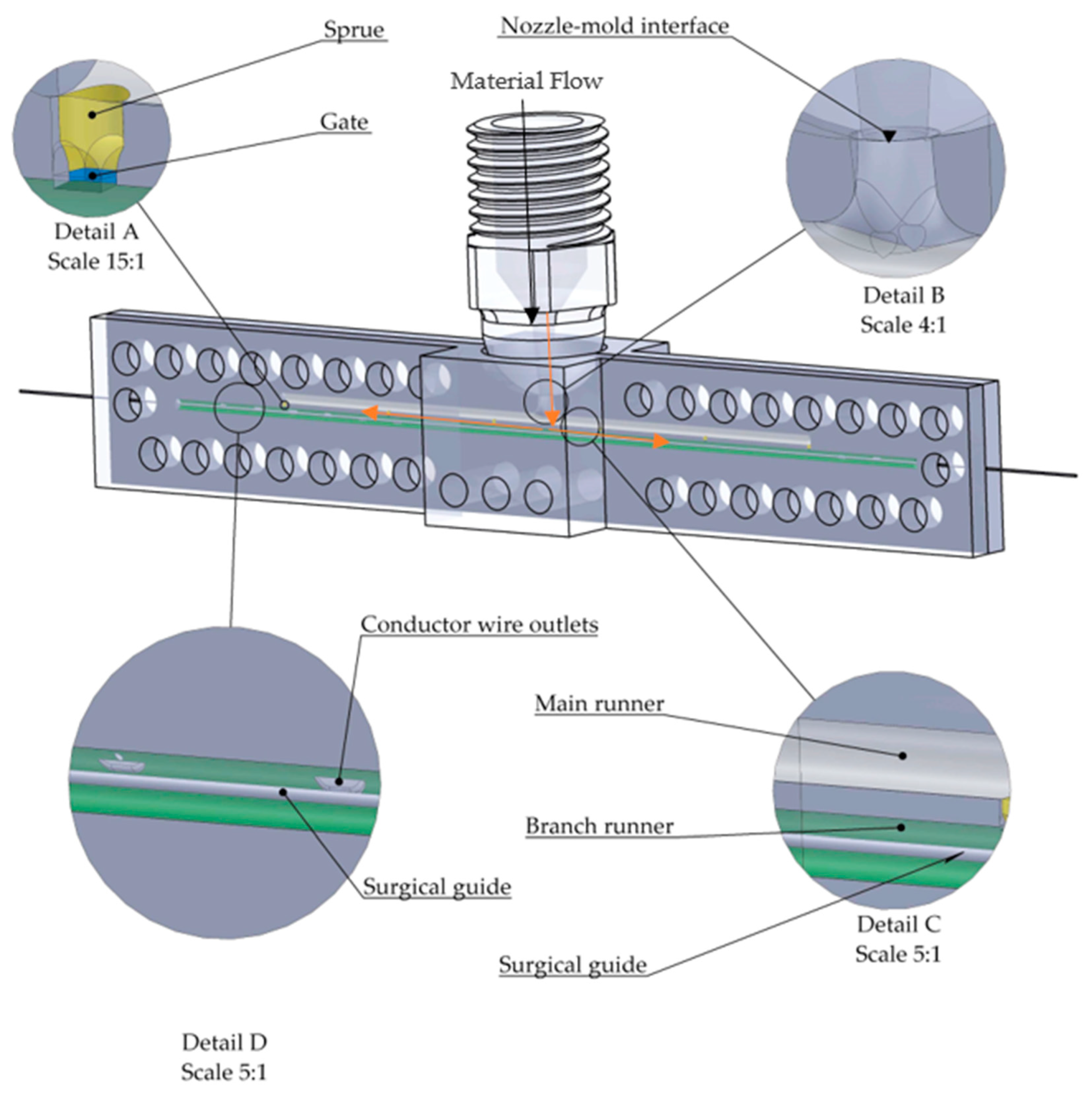
3.1. Hot Casting Injection

The injection process for the prototype considers a mold made of aluminum 7075, where experimental runs for this process vary according to the injection temperature of the Polyamide. Figure 9 shows the mold design that can be attached to the selected equipment, using a 5-3 configuration for the number of inputs and outputs of the electrode’s conductor wire.
Figure 9 shows the mold coupling and the filling channel with the nozzle coupling.

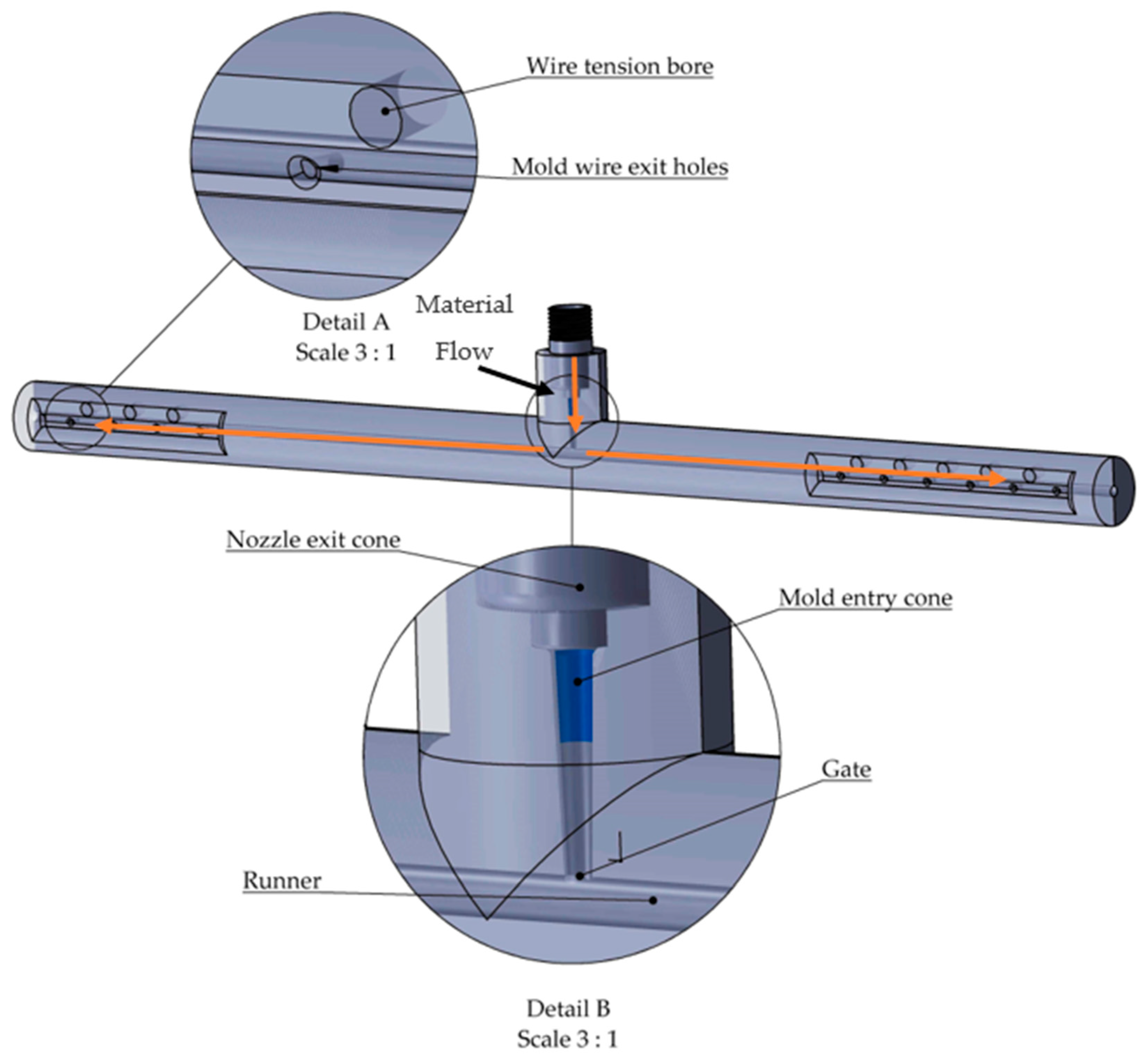
3.2. Cold Casting Injection

The generated prototypes define the control of variables to have a successful injection, so different mold configurations have been tested, where attachment points, number of obstacles, nozzle–mold couplings, and injection points are varied. Figure 10 shows the mold prototype.
Figure 11 shows an injected and stapled DBS electrode to its core.
The stapled electrode requires post-processing on the rings to maintain the aesthetics of the stapled ring. However, the adherence by microdot with the conductor wire is good because the ring cannot be detached from the electrode anymore. Thus, it is a manufacturing proposal that is subject to change depending on future tests and new proposals for stapling the rings to the electrode.
Various types of electrodes were obtained. For cold casting injection, an electrode with a configuration of five threads, five rings, five threads, four rings without a guide with a silver core, and a hypoallergenic silicone coating was obtained. It was stapled with surgical-grade stainless steel rings, as shown in Figure 12.
Once a successful DBS electrode is obtained, the process is documented using a roadmap, as shown in Table 4.

4. Conclusions

It is concluded that two types of electrode injections of 300 mm in length and 2 mm in diameter were carried out: cold casting injection and casting at higher temperatures. In both cases, a safety factor of 1.5 to 3 must be applied; however, the hot casting tolerance is 0.1 mm, and the outlet angles for die forming are 1°. In cold casting, the tolerances are 0.22 mm, and the angles of release for de-molds are from 2° to 3°. For cold casting mold, the same type of setting is used, but with a tolerance different due to shrinkage of the material. This is because the mold is manufactured by 3D printing, which consists of the deposition of layers of a molten polymer. The parameters considered in relation to the electrode are the coating diameter, the electrode length, the use of a guide, and the change of coating material. The wall thickness for cold casting was 4 mm higher than in hot casting. Cold casting injection was efficiently generated with a 5-4 unguided ring configuration with a silver core and hypoallergenic silicone coating, stapled with surgical-grade stainless steel rings.
Functionality testing is required, primarily due to the changes in electrode customization that involve different configurations of conductive wires, number of rings, and electrode length. The DBS electrode requires an immaculate process, so there are certain limitations due to the lack of study on the cold casting injection technique, as it may contain some impurities and burrs that need to be removed. The necessary design parameters for the manufacture of a DBS electrode have been calculated, allowing for clear and precise guidelines for its production.

Author Contributions

Conceptualization, C.R.T.S.M. and J.E.M.-R.; methodology, C.R.T.S.M.; software, K.N.S.-G.; validation, C.R.T.S.M. and J.E.M.-R.; formal analysis A.J.P.-D.; investigation, J.A.F.-C. resources, C.R.T.S.M.; data curation, A.O.-O.; writing—original draft preparation, J.E.M.-R.; writing—review and editing C.R.T.S.M.; visualization A.O.-O. and A.J.P.-D.; supervision, C.R.T.S.M.; project administration, C.R.T.S.M.; funding acquisition, C.R.T.S.M. All authors have read and agreed to the published version of the manuscript.

Funding

The authors are thankful to the Consejo Nacional de Humanidades, Ciencia y Tecnología (CONAHCyT), and the Instituto Politécnico Nacional for the support received in 20240701 and 20242785, as well as an EDI grant, all from SIP/IPN.

Data Availability Statement

Data are contained within the article.

Acknowledgments

The authors are thankful to the Instituto Politécnico Nacional and an EDI grant from SIP/IPN.

Conflicts of Interest

The authors declare no conflicts of interest.

References

  1. Parkinson Disease. Available online: https://www.who.int/news-room/fact-sheets/detail/parkinson-disease#:~:text=Global%20estimates%20in%202019%20showed,of%20over%20100%25%20since%202000 (accessed on 7 April 2024).
  2. Kulisevsky, J.; Luquin, M.R.; Arbelo, J.M.; Burguera, J.A.; Carrillo, F.; Castro, A.; Chacón, J.; García-Ruiz, P.J.; Lezcano, E.; Mir, P.; et al. Advance Parkinson’s disease: Clinical Characteristics and treatment: Part II. Neurología 2013, 28, 564–565. [Google Scholar]
  3. Deep Brain Stimulator. Available online: https://www.sciencedirect.com/topics/nursing-and-health-professions/deep-brain-stimulator (accessed on 7 April 2024).
  4. Sibylle, D.; Paul, E.H. Deep brain stimulation in the treatment of depression. Dialogues Clin. Neurosci. 2014, 16, 83–91. [Google Scholar]
  5. Meijuan Zhou, D.O.U. Electrodo de Estimulación Cerebral Profunda, Dispositivo y Método. Patente. MX2017004133A, 31 October 2017. [Google Scholar]
  6. Moffitt, M.A.; Oleksyn, T.A.; Bradley, K.; Peterson, D.K.L.; Lane, C.; Pianca, A.M. Deep Brain Stimulation Current Steering with Split Electrodes. U.S. Patent 14542401, 14 November 2014. pp. 18–19. [Google Scholar]
  7. Sasse, P.; Chambers, T.; Kummer, R.D.; Armstrong, J.; Reece, D.; Lam, H. Method of Manufacturing Electrical Cable, and Resulting Product, with Reduced Required Installation Pulling Force. U.S. Patent US11776715B2, 3 October 2023. [Google Scholar]
  8. Sasse, P.; Andrea, T. Electrical Cable Having Crosslinked Insulation with Internal Pulling Lubricant. U.S. Patent US11046851B2, 29 June 2021. p. 21. [Google Scholar]
  9. Draz, H.H.; Gabran, S.R.I.; Basha, M.; Mostafa, H.; Abu-Elyazeed, M.F.; Zaki, A. Comparative mechanical analysis of deep brain stimulation electrodes. Biomed. Eng. Online 2018, 17, 123–129. [Google Scholar] [CrossRef] [PubMed]
  10. Tool—Temp International. Available online: https://tooltemp.com/es/sectores-sistemas-de-control-de-temperatura/plastico-inyeccion-sistema-decontrol-de-temperatura/ (accessed on 8 April 2024).
  11. Torres-Sanmiguel, C.R.; Hernández-Gómez, J.J.; Urriolagoitia-Sosa, G.; Romero-ángeles, B.; Martínez-Sáez, L. Design and manufacture of a customised temporomandibular prosthesis. Rev. Int. Metodos Numer. Calc. Diseno Ing. 2019, 35. [Google Scholar] [CrossRef]
  12. Paulson Training Programs. Available online: https://www.paulsontraining.com/simtech-challenge/ (accessed on 8 April 2024).
  13. Menges, G.; Mohren, G. Moldes para Inyección de Plásticos, 3rd ed.; Figure 28; Editorial Gustavo Gili, S.L.: Barcelona, Spain, 1983; pp. 47, 59, 60. [Google Scholar]
  14. Moffitt, M.A.; Olenksyn, T.A.; Bradley, K.; Peterson, D.K.L.; Lane, C.; Margaret, A.; Monica, P.S. Deep Brain Stimulation Current Steering with Split Electrodes. U.S. Patent US9211402B2, 15 December 2015. p. 18. [Google Scholar]
  15. Bronstein, J.M.; Tagliati, M.; Alterman, R.L.; Lozano, A.M.; Okun, M.S. Deep brain stimulation for Parkinson disease: An expert consensus and review of key issues. Mov. Disord. 2011, 68 (Suppl. S2), 165. [Google Scholar] [CrossRef] [PubMed]
  16. Schlaepfer, T.E.; Lieb, K. Deep brain stimulation for treatment of refractory depression. Lancet 2005, 366, 1420–1422. [Google Scholar] [CrossRef] [PubMed]
  17. Zhang, J.; Li, J.D. Development of a Computational Model for Prediction of Response to Deep Brain Stimulation in Obsessive-Compulsive Disorder. Front. Comput. Neurosci. 2014, 8, 100. [Google Scholar]
  18. Philpot, T.A. Mechanics of Materials, 4th ed.; Missouri University of Science and Technology: Rolla, MO, USA; Wiley: Hoboken, NJ, USA, 2017; p. 604. [Google Scholar]
  19. Akulon. Akulon IG-HG7. Available online: https://plasticsfinder.envalior.com/en/datasheet/Akulon%C2%AE%20IG-HG7/p2dqO (accessed on 15 November 2024).
Figure 1. The electrode’s geometry and its constituent parts.
Processes 12 02694 g001
Figure 2. Mold parameters for high-temperature injection [13].
Processes 12 02694 g002
Figure 3. Free body diagram of a thick-walled cylinder for the design of a hot casting mold.
Processes 12 02694 g003
Figure 4. High-temperature mold design.
Processes 12 02694 g004
Figure 5. Free body diagram for low-temperature injection mold.
Processes 12 02694 g005
Figure 6. Design of room temperature injection mold.
Processes 12 02694 g006
Figure 7. (a) Recommended coupling in the literature; (b) designed coupling.
Processes 12 02694 g007
Figure 8. Injection nozzles with flat and concave couplings.
Processes 12 02694 g008
Figure 9. (a) Nozzle channel; (b) mold–nozzle assembly.
Processes 12 02694 g009
Figure 10. Cold casting injection mold.
Processes 12 02694 g010
Figure 11. DBS electrode stapled to two rings.
Processes 12 02694 g011
Figure 12. Deep brain stimulation (DBS) electrode with a diameter of 2.3 mm.
Processes 12 02694 g012
Table 1. High-temperature mold calculation using tables.
ParametersAvailable EquipmentSelected Liquid Plastic (Low-Pressure Injection, Plastic Developed for 3D Printing)Liquid Plastic (High-Pressure Injection)
Flow path300 mm300 mm300 mm
Electrode diameter2 mm2 mm2 mm
MaterialN/ASnapPrint PA6PA6 or 12
Average inlet pressure (P)0.8 MPa0.5 MPa–2 MPa17.5 MPa
Projected area (S)18.84   c m 2 18.84 c m 2 18.84   c m 2
Thrust force (PxS)1507.944 N or
153.71 kg
942.46 N or
96 kg
32.986 KN or
3.36 tons
Mold clamping force177 kg111 kg4 tons
Table 2. Theories for calculating high-temperature mold.
Applied TheoriesEquation Results (MPa)
Theory of thick-walled vesselsr) max = −Po 0.92
Theory of thick-walled vessels σ θ m a x = ( b 2 + a 2 ) P i 2 b 2 P 0 b 2 a 2 1.042
Failure theory, Von Mises criterion σ v m = σ r 2 σ r σ θ + σ θ 2 0.986
Table 3. Mold calculation theories.
Applied TheoriesEquation Results
Theory of thick-walled vesselsr) max = −Po−0.634 MPa
Theory of thick-walled vessels σ θ m a x = ( b 2 + a 2 ) P i 2 b 2 P 0 b 2 a 2 −0.719 MPa
Failure theory, Von Mises criterion σ v m = σ r 2 σ r σ θ + σ θ 2 0.681 MPa
Safety factor S . F . = σ y σ v m 3.4
Table 4. Roadmap for obtaining a DBS electrode.
OperationDescriptionMachine TypeTool PreparationPreparation Time
(min)
Operation Time
(min)
Material Part
1MountingManual operationInjectir preparation2 0Manual injector
2AssemblyManual operationMold assembly 1 with electrode wires15 0Mold made by FDM
3AssemblyManual operationAssembly of mold 1 with mold 2100Mold made by FDM
4AssemblyManual operationClamps assembly on the complete mold10 0Clamps made by FDM
5MixedManual operationHomogenization of equal parts of fluid A and fluid B1 Silicon plus catalyst for hardening by smoothing on
6InjectionManual InjectorSilicon Injection prepared in a mold1 10 Smooth on manual injector
7DryingManual operationWaiting time at rest of the injected mold0480 Not apply
8DisassemblyManual operationRemoval of the screw from clamps 2 10 Not apply
9DisassemblyManual operationDisassembly of mold 2 with mold 12 10Not apply
10DisassemblyManual operationMold electrode demolding 12 5 DBS electrode injected into a conductive core
11StapledManual operationStamping of the conductive rings with the conductive core Conductive material rings
Disclaimer/Publisher’s Note: The statements, opinions and data contained in all publications are solely those of the individual author(s) and contributor(s) and not of MDPI and/or the editor(s). MDPI and/or the editor(s) disclaim responsibility for any injury to people or property resulting from any ideas, methods, instructions or products referred to in the content.

