Article

Enhancing Engine Cylinder Heat Dissipation Capacity Through Direct Optimization (DO) Techniques

by
Abhishek Agarwal
1,*,
Megersa Olumana Dinka
2 and
Masengo Ilunga
3
1
Department of Mechanical Engineering, College of Science and Technology, Royal University of Bhutan, Phuentsholing 21101, Bhutan
2
Department of Civil Engineering Science, University of Johannesburg, APK Campus, Johannesburg 2006, South Africa
3
Department of Civil Engineering, University of South Africa, Pretoria 1709, South Africa
*
Author to whom correspondence should be addressed.
Processes 2024, 12(12), 2659; https://doi.org/10.3390/pr12122659
Submission received: 28 October 2024 / Revised: 15 November 2024 / Accepted: 21 November 2024 / Published: 25 November 2024

Abstract

:
Internal combustion (IC) engines are used widely as the primary power source for automobiles of all types, cars, motorcycles, and trucks. Because of the high combustion temperatures involved in the operation, the excess heat is removed by means of extended fins that increase the surface area for adequate cooling. Significant improvement in the heat dissipation characteristics of the engine cylinder can be achieved by optimizing the design of these fins. The aim of this study is to evaluate the thermal performance of engine cylinder fins using an analytical system of finite element analysis (ANSYS FEA) software, using a direct optimization (DO) approach to identify optimal fin design. Analysis shows that fin length and width play critical roles in improving cooling efficiency, lowering the maximum temperature within the cylinder to 549.46 K and enhancing total heat flux to 7225.31 W/m2, which is a 25.87% increase from the generic design, capable of heating removal of 5740.22 W/m2. The current fin design is effective but could be improved in heat dissipation, mainly at fin tips. To optimize thermal performance while minimizing material costs, a balanced fin dimension is recommended. Alternative materials, transient heating analysis, and experimental verification may be examined in the future to achieve a total understanding of fin geometry and behavior under real operating conditions. These insights lay a foundation to accelerate cooling systems development in the automotive, aerospace, and heavy equipment industries, where efficient heat transfer is key for performance and long-term durability.

1. Introduction

Internal combustion (IC) engines are indispensable components of a variety of applications including automobiles and industrial equipment [1]. The cylinder block is at the core of fuel combustion, producing high temperatures because of fuel combustion [2]. In extreme cases, the temperature can be as high as 2500 °C (or 4500 °F) during the combustion process [3]. That kind of intense heat can break down the lubricating oil layer that is needed to offset friction in moving parts. Lack of adequate thermal management results in a real risk of mechanical failure, for example, with components seizing, or welding closed, due to overheating [4]. Maintaining engine performance and durability, and preventing thermal-induced damage, requires efficient heat dissipation. Thermal loads beyond the limits of the engine can cause thermal stresses that reduce efficiency, increase the wear of engine components, and, in extreme cases, result in catastrophic engine failure [5]. Thus, improved cooling solutions should be developed to enable IC engines to run reliably under a long duration and at high stress. An effective method of enhancement of heat dissipation is the use of fins, i.e., extended surfaces that exponentially increase the area available for heat transfer [6]. The fins attached to the engine cylinder improve the heat transfer capability by improving convection and radiation heat removal more effectively, as shown in Figure 1.
The overall effectiveness of the cooling depends critically on the design of these fins including their geometry, material composition, and arrangement. Fin structures are important, though, because they not only offer a low-cost solution but confer substantial thermal performance without introducing large amounts of production complexity or cost [8]. Fins have been used as a widely adopted solution for heat dissipation in internal combustion engines; nonetheless, the design optimization of fins to specific application requirements constitutes a difficult engineering problem [9]. The reason for this challenge lies in the need to balance a number of objectives, including maximizing thermal efficiency, manufacturability, and production cost control. To address this complex question, this research uses direct optimization (DO) techniques [10] to systematically tune fin geometry and other key design parameters. The goal is to improve the thermal dissipation capability of the engine cylinder within practical manufacturing constraints.
The comprehensive thermal performance of various fin designs is assessed with the use of the advanced capabilities of the ANSYS FEA platform. The study focuses on investigating the insights generated in the different configurations to identify those that lead to the best heat dispersal efficiency design. The findings should address not only increasing the cooling efficiency of internal combustion engines but also serve as a valuable resource for guiding continued innovation in engine design for the automotive, aerospace, and heavy machinery industries. The present study takes a step further and optimizes the thermal performance of the engine cylinder fins on the basis of this foundation. Previous research has investigated many different fin designs and cooling strategies for internal combustion engines, but many studies have either looked at generalized configurations or focused on specific cases without a comprehensive optimization approach. Systematic refinement of the fin design parameters, geometry, and material properties through advanced simulations still offers a large margin for improving fin cooling efficiency. This study aims to fill these gaps by leveraging computational methods such as direct optimization (DO) in combination with finite element analysis (FEA) to push the boundary of heat dissipation capabilities in IC engines. In the following literature review, we examine the current literature dealing with engine cylinder fins and what has been achieved technically to bring us to this point. It will also identify unresolved challenges and future work areas and broadly frame the objectives and contributions of this current study. Babu et al. [11] carried out extensive simulation studies on the thermal behavior of engine cylinder fins based on the ANSYS finite element analysis (FEA) simulation package. To predict the transient thermal performance of a cylinder with fins they used parametric models that have variable fin thickness and geometry including curved, circular, and rectangular designs. Pro/Engineer was used for 3D modeling and the thermal properties of aluminum alloy 204 have been evaluated, which has a thermal conductivity range of 110–150 W/m·K. The findings also highlight the enhanced heat transfer capability of the cylinder block with different fin configurations and set forth the first foundational ideas on how the fin geometry affects thermal performance.
K. Angamuthu et al. [12] also studied alternative materials like magnesium alloy 6061 that have comparatively good thermal conductivity, and potentially better heat dissipation properties. This research underscored the value of material selection for maximum thermal efficiency in engine components, important information for our study. Mahek et al. [13] compared the thermal analysis of a Stirling engine with and without fins using ANSYS software. After examining a range of fin geometries and thicknesses, they found that rectangular fins yielded the best thermal performance, a result that is fully in line with our research topic. In the study by Avinash et al. [14], they studied thermal distribution and heat flux to thermal strains of the BAJAJ 150CC engine block, over different fin designs, using ANSYS. After developing a 3D computer-aided design (CAD) model with SolidWorks, they concluded with an optimized square-shaped fin with filleted edges and superior thermal characteristics, justifying their goal of optimizing fin geometry for maximum thermal efficiency. The cooling potential of stator lamination fins in radial permanent magnet motors was investigated by Dobzhanskyi et al. [15]. Their study maximized heat transfer by using computational fluid dynamics (CFD) and finite element modeling to identify optimal fin count and thickness. Their methodological approach to fin design has insight that rings true to our optimization efforts as exploring the interactions of fin design and thermal performance. The thermal performance of pin fins versus plate fins was analyzed by Saxena et al. [16] using ANSYS with particular attention to the role of surface perforations on the rate of heat transfer. Innovative fin configurations were found to be critical for improving thermal efficiency, a principle that our research is also focused on.
By varying the cylinder geometry, material, and profile, S.K. Mohammad Shareef et al. [17] quantified the thermal properties of engine cylinders using ANSYS Work Bench. Angular profiled fins were shown to produce the highest heat flux and lowest temperatures, indicating that fin profile optimization can significantly increase thermal performance. The effect of engine cylinder fin shape on heat transfer characteristics under forced convection conditions was studied by Agarwal et al. [18]. A consistently observed relationship with all shapes investigated was identified in regions of high heat transfer rates, located at diametrically opposite positions. The results show that the heat transfer coefficient and heat flux are significantly influenced by the flow patterns. The importance of understanding fluid dynamics for the design and optimization of the engine cylinder fins is highlighted by this research. Khan et al. [19] examined engine cylinder variations in fin thickness and material using ANSYS FEA simulations for a detailed analysis. The results reveal that conventional aluminum alloy fins heated up to 15.3% more than the magnesium alloy fins. This focus on both material and geometric variation in their study supports our research emphasis on material and geometric optimization of critical factors.
Chaitanya et al. [20] performed a thermal analysis of cylinder fins via ANSYS workbench, applying transient thermal behavior variables such as fin shape, material, and thickness. Aluminum alloy 6061 is found to have a higher heat dissipation capacity compared with aluminum alloy 204 by 5.4%, a result which is consistent with the material evaluations conducted in the study. Sandeep Gupta et al. [21] looked at different fin shapes ranging from convex and tapered to triangular or rectangular types in 3D modeling using SolidWorks and steady-state thermal analysis in ANSYS. The results show that convex cylinder fins provided improved heat transfer characteristics of 8.2%, highlighting how innovative fin shapes can enhance thermal performance, which is the aim of our study.
Kumaravelu et al. [22] studied the effect of different fin geometries (circular, pin, rectangular) on Stirling engine efficiency. The numerical analysis provided against previous studies was validated and revealed that fins had a positive impact on heat transfer rates as well as overall engine performance. Rectangular fins were proven to have the highest efficiency among fin types with 19.03% efficiency, mainly resulting from their large surface area and superior thermal properties. This research demonstrates the fundamental role of fin design in achieving thermal performance optimization in engine applications. Paweł Ocłoń et al. [23] conducted a detailed study of computational fluid dynamics (CFD) on the flow distribution in the tubes of a fin and tube heat exchanger. In addition, their structural analysis based on ANSYS was used to quantify the thermal stresses in the system. In particular, the introduction of a novel design for the heat exchanger manifolds contributed to a reduction in the tube wall temperature from 185 °C to 134 °C. This innovative design also resulted in a remarkable fivefold decrease in compressive stresses within the heat exchanger construction from 105 MPa to 23 MPa in the fin-and-tube heat exchanger manifolds, when compared with traditional fin-and-tube heat exchanger manifolds. These results demonstrate that advanced design approaches hold promise to improve the thermal performance and structural integrity of heat exchangers, and are relevant to our optimization objectives.
Sharon Z. Varghese et al. [24] performed an analytical study on a conventional circular type of fin array, where heat dissipation and material selection were focused upon. A non-dominated sorting genetic algorithm II (NSGA-II) was used to generate a set of optimal, Pareto-efficient designs for a 100 cc engine cylinder fin array subject to maximum heat transfer. Genetic algorithms combined with CFD analysis in this research are effectively combined to produce a robust optimization framework. The outcomes indicate that the proposed method is both efficient and reliable, and the proposed method has good potential to substantially improve the engine fin array optimization process. These findings are complementary to our research objectives, particularly the need for advanced optimization techniques to enhance the thermal management of engine components.
Nahum Y. Godi [25] investigated the impacts of geometric variations and hybridization on micro heat exchangers with cylindrical fins in order to improve thermal conductance. The study shows that half-hollow fins have 16.4% greater thermal conductance than solid fins, and only 0.14% higher than hollow fins in parallel flow. Half-hollow fins in counterflow can achieve 5% higher thermal performance than solid fins and 0.5% higher than hollow fins, giving insight into fin design optimization. Thus, considerable research has been conducted on the thermal performance of engine cylinder fins, but only limited work has been carried out to systematically optimize fin designs using advanced computational techniques. Previously, most studies have focused on analyzing the fin shapes and materials separately and ignored the convergence of multiple design parameters. In addition, existing research typically does not provide a complete evaluation of the effect of the design variation on heat dissipation characteristics in the context of real-world operating conditions. Thus, this study attempts to close this gap through the use of direct optimization (DO) methods to improve the design of engine cylinder fins to enhance their heat dissipation potential. The optimization of engine cylinder fin designs using direct optimization techniques is expected to offer a significant improvement in heat dissipation characteristics of internal combustion engines.
In particular, it is hypothesized that the optimized fin configurations will have higher thermal performance than conventional fin designs and ultimately provide an increased engine efficiency and longevity. It follows that the main research questions we are discussing are:
  • How do different fin geometries and thicknesses influence the thermal performance of engine cylinder fins in internal combustion engines?
  • What is the impact of various materials on the heat dissipation characteristics of optimized fin designs?
  • How can direct optimization techniques be effectively applied to enhance the thermal efficiency of engine cylinder fins?
  • What are the optimal design parameters (geometry, thickness, and material) that yield the maximum heat dissipation for engine cylinder fins?
Thermal management of the engine cylinder fins plays a key role in the performance of the internal combustion engine, as its ability to dissipate heat has a dramatic impact on the engine’s performance. Existing research attests to a higher heat dissipation introduced by fin configurations, yet extensive studies that utilize advanced computational methods, including direct optimization (DO), are severely lacking from the literature on the effects of fin configurations in enhancing the heat dissipation characteristics of engine cylinder fins. A significant gap that this research attempts to fill is by systematically evaluating and optimizing the fin designs using the ANSYS FEA simulation package. The objective is to estimate the best fin configuration that maximizes heat dissipation and, therefore, improves the overall engine performance and reliability.

2. Materials and Methods

In this study, the thermal performance of fins attached to a single-cylinder, 4-stroke, air-cooled internal combustion engine is analyzed. This type of engine is commonly used in smaller motorcycles and automobiles. The engine operates in an ideal mode at 1000 RPM, representing a low-speed condition with reduced fuel consumption and heat generation [26]. During this mode, the vehicle remains stationary, resulting in minimal airflow over the fins. As such, heat dissipation occurs primarily through natural convection, as is typical for idle conditions in such engines [27,28]. This section provides the approach used in this study to assess the thermal performance of the engine cylinder fins with the help of ANSYS workbench simulation software. The approach comprises several critical steps: formation of a 3D solid model, generation of the meshing, application of thermal boundary conditions, and configuration of solver setting [29]. All the steps are crucial to obtain maximum confidence in the simulation results, which is critical to making sound assessments of fin performance.

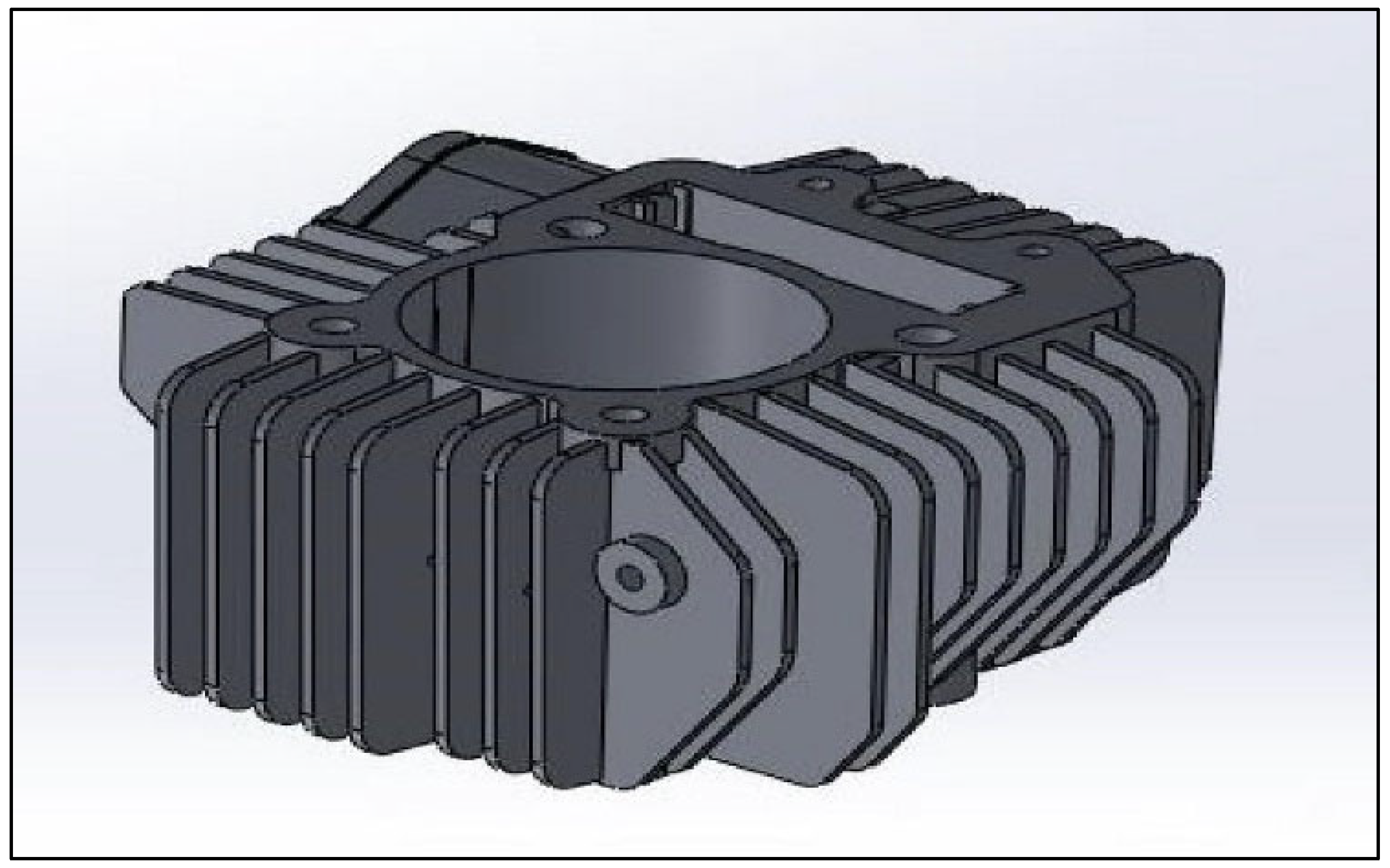
2.1. Development of the 3D Model

The first step is to build a precise 3D model of the engine cylinder with the integrated fin structures. The design modeler in ANSYS is used to create this model due to the robust interface needed to design complex geometries. The process captures the physical dimensions and configuration of the engine cylinder and its fins very accurately in terms of sketching and extruding techniques. This detailed representation of the geometry is necessary because even small variations in geometry can have a big impact on thermal performance. To ensure that the fin configuration matches industry standards, dimensions are drawn from the existing literature [30]. The importance of this approach comes from its ability to validate the model against real-world data, which increases the relevance of the results. The pattern tool is used to produce multiple fins, which facilitates the efficient replication of fin design based on the given parameters.
The design intricacies of the engine cylinder with fins are shown in Figure 2, which illustrates the CAD model. The importance of accurate geometry lies in its direct effect on thermal performance, because fin shape, size, and arrangement can noticeably influence heat transfer characteristics.
The specifications of the engine block are outlined in Table 1, which include stroke, bore, number of fins, fin pitch, thickness, and material. Cast iron is chosen as the fin material on the basis of its superior thermal conductivity and mechanical properties that optimally favor heat dissipation in the internal combustion engines [21].

2.2. Meshing the Model

After setting the geometry, the next important step is the discretization of the model through meshing. Hexahedral elements are chosen due to their efficiency in capturing complex geometries and maintaining numerical stability, where the model is discretized. Unlike tetrahedral elements, hexahedral elements enable better performance in thermal analysis, with superior accuracy and faster convergence properties. Standard thermal analysis requirements apply to the meshing process. For the accurate thermogradients capture, a mesh growth rate of 1.4 with normal inflation is used, which helps in preserving the mesh size near the boundaries in a gradual manner.
Furthermore, the transition ratio of 0.275 provides a smooth transition between different mesh regions and six layers of inflation improve resolution at critical boundary interfaces where heat transfer takes place. Figure 3 shows that the discretization leads to 84,569 elements and 100,259 nodes. High resolution in this fine mesh is critical to the analysis of temperature distribution and heat flux [31,32], both indicators of thermal engine cylinder fin performance.

2.3. Application of Thermal Boundary Conditions

Since the model is meshed successfully, steady-state thermal boundary conditions are applied for accurate simulation of internal combustion engine operating conditions. The thermal loading applied to the engine cylinder is demonstrated in Figure 4. The red-colored zone represents the temperature of 311.85 °C being imposed by the inner wall of the cylinder. This temperature was chosen based on values from the literature and real-world engine data, which corresponds to conditions in typical internal combustion engine conditions during peak operating. This temperature is used to maintain a realistic simulation of actual engine operation in order to assess the heat dissipation capabilities of the fins under high thermal loads.
An ambient temperature of 295 K and a convection coefficient of 5 W/m2 are applied to the fins [33]. Modeling the heat transfer processes between the fins and the surroundings requires these boundary conditions, which are critical for modeling the thermal performance and cooling efficiency of the engine fins. The convection boundary condition is depicted by the yellow-colored zone in Figure 3, emphasizing the interaction between the fins and the ambient air, which significantly affects overall heat dissipation.

2.4. Heat Balance and Thermal Management

In the heat balance of an engine, the thermal energy generated during combustion is distributed across various components. This distribution includes useful work, heat rejected through the cooling system, heat lost via exhaust gases, and other miscellaneous losses. The cooling system’s efficiency, crucial to maintaining the engine’s overall thermal balance, is directly affected by the design and optimization of fins. Enhancing fin geometry, material, and surface area can improve the cooling system’s ability to reject heat, thereby boosting engine performance and reducing thermal losses. The major heat balance components include heat generated by combustion Qcombustion, useful work Qwork, heat rejected by cooling system Qcooling, and heat loss to exhaust gases Qexhaust. The total heat balance equation is expressed as follows [34]:
Qcombustion = Qwork + Qcooling + Qexhaust + Qmisc
In this context, Qcooling represents the heat removed by the cooling system and is the primary focus of this study regarding fin design optimization.

2.5. Solver Settings

Thermal boundary conditions are established, and appropriate solver settings are defined to analyze. This study chooses a conjugate gradient (CG) solver [35] type as it is efficient in solving large-scale thermal problems, especially for problems where sparse matrices were generated while meshing. The CG solver is well suited to thermal analysis because it is also fast to converge even in complex geometries, resulting in increased efficiency in computation. The reason for the choice of solver is due to the fact that this study involves a large number of elements and nodes. An efficient solver is used to ensure that the simulation produces reliable results with minimal computational delay, thus making it possible to explore multiple design iterations during optimization [36].
The methodology used in this study is applied to study the thermal characteristics of engine cylinder fins. The research utilizes advanced simulation techniques to ensure simulation accuracy and application relevance, by leveraging the capabilities of the ANSYS workbench simulation platform. It is important for capturing heat transfer complexities in real-world scenarios to detail the attention to geometric representation and thermal boundary conditions. Additionally, the combination of direct optimization techniques permits a thoughtful study of how design variables affect thermal performance. This structured approach helps establish, prior to further analysis, other actionable insights on how to optimize fin designs for improved engine efficiency. The results are presented in the following sections and discussed in terms of their implications for engine thermal management.

3. Results

3.1. Thermal Distribution Across Engine Cylinder Fins

Figure 5 illustrates the temperature distribution across the engine cylinder and its fins to provide critical insights into the thermal performance of the system. The cylinder’s highest temperature is reached by the inner wall at 311.85 °C, which is considered the maximum expected temperature for engines operated under high-performance conditions with high-intensity combustion processes. The high temperature shown in this result implies that the engine cylinder is generating heat efficiently. The fins are then subjected to an ambient temperature of 301 K and convection coefficient of 5 W/m2K, to simulate the heat transfer to the surrounding air.

3.2. Grid Independence and Validation

The model’s obtained temperature distribution closely agrees with the previous literature [8,9,10], verifying the accuracy of the model. From the analysis, the maximum temperature is found to be 307.8 °C (consistent with previous studies [21]). Such validation is critical for ensuring that the simulation results correspond to the actual environment, adding support to the strength of the methodology used. A grid independence test was conducted in order to ensure the accuracy of the results, as shown in Table 2. This test analyzed the influence of mesh density on the temperature outcome, and, hence, reliability of the computational model. The results indicate that with an increasing number of elements, temperatures stabilize, reaching values between 305.1 K and 307.8 K. The stabilization indicates that this size of mesh can give reliable results, which confirms that the model can accurately represent the thermal behavior of the engine cylinder.
The findings from this grid independence test corroborate more strongly the model validation with the experimental results of previous studies, thus ensuring the overall validity of all the analyses.

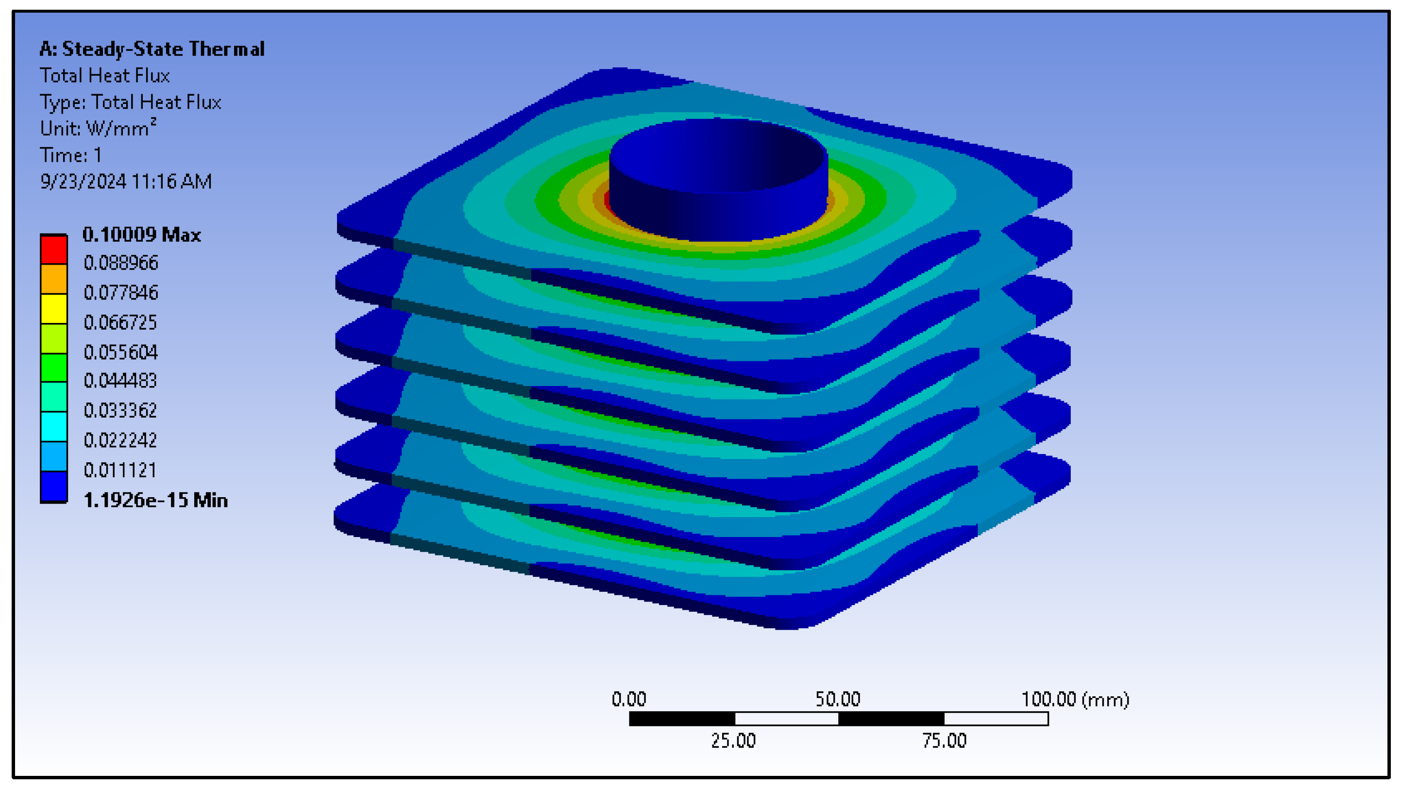
3.3. Total Heat Flux Distribution in Engine Cylinder

The total heat flux distribution across the engine cylinder and fins is shown in Figure 6 with the highest heat transfer locations. The plot shows that the heat flux values are higher at the base of the fins linking to the cylinder blocks representing the main heat generating zone. This observation supports the principle that heat flow rates are higher in areas where the temperature gradient is steepest, resulting in a more efficient heat transfer process [37,38].
As the heat conducts along the fins, the heat flux decreases towards the tips, highlighting a significant reduction in thermal effectiveness in these regions. This decline in heat flux can be attributed to the decreasing temperature difference between the fin surfaces and the surrounding air at the fin tips, which suggests that the current fin design may not optimize heat dissipation effectively.
Figure 7 further illustrates this phenomenon through a vector plot of heat flux, where arrows represent the direction of heat flow and their thickness indicates the density of heat flux on the engine components. The heat flux vectors are notably directed toward the base of the fins, which signifies the most efficient heat transfer zones. As illustrated in Figure 7, the lengths of these vectors diminish towards the tips of the fins, indicating reduced thermal conductivity in these areas [39,40].

3.4. Optimization Results

This study aims to enhance the thermal dissipation efficiency of engine fins by systematically optimizing key geometric parameters: fin length (L) and fin width (W). The optimization objective is twofold: (1) to minimize the maximum temperature (Tmax) on the fin surface to eliminate thermal hotspots; and (2) to maximize the total heat flux (q), i.e., the fin’s overall heat dissipation capability. The direct optimization (DO) method simultaneously optimizes multiple parameters to find optimal configurations that meet both thermal performance criteria. The optimization is governed by an objective function f that combines these goals through weighted terms for temperature reduction and heat dissipation [41,42]:
f = T m a x T r e f + β q q r e f
A design variable space is explored through the optimization process shown in Table 3 and Table 4, seeking design improvements in the heat dissipation performance of the engine cylinder. Two critical geometrical parameters were optimized. The fin length and width were chosen, to minimize the extreme temperature while keeping the total heat flux constant. The study employed the direct optimization definition shown in Figure 8, which shows the parameters and constraints used for the optimization process.
The results of optimization show large variations in maximum temperature and heat flux over the design points, indicating the significant influence of fin geometry on thermal properties.
These optimizations led to maximum temperatures between 545.68 K and 567.09 K and total heat fluxes of between 3145.56 W/m2 and 7233.41 W/m2. The results highlight the strong dependence of thermal performance on fin geometry. In particular, fins that are longer and wider, and, thus, have a greater amount of surface area, have lower maximum temperature because of their superior surface area, which enhances heat dissipation.

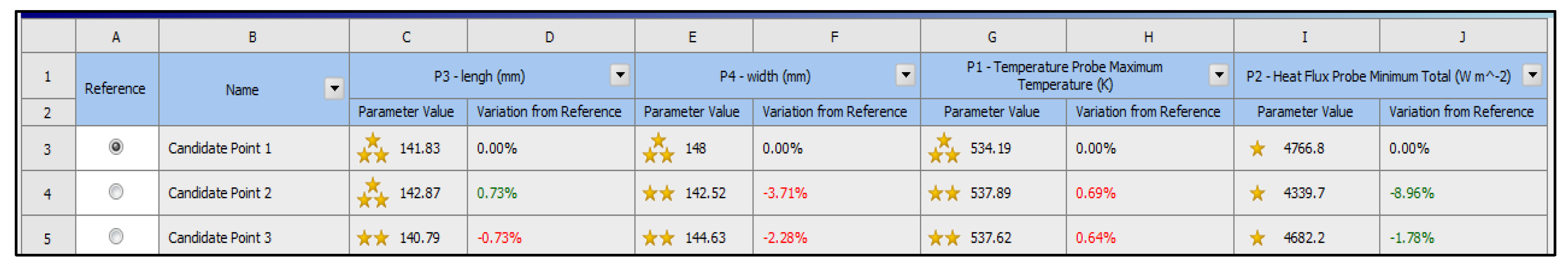
3.4.1. Optimal Design Point

This study identified the optimal design point for the fins to have a length of 124.67 mm and a width of 141.04 mm with a maximum temperature of approximately 549.46 K and a total heat flux of 6319.59 W/m2. This is because the size of the fin length and width provides a good balance of cooling the engine and the amount of material that one needs to use on the fins. Figure 8 is a ‘samples chart’ where candidate designs generated in the optimization process are shown. Each path (colored lines) represents candidate designs. This path represents a specific combination of fin length and width, which enables us to evaluate the influence of fin geometry on Tmax (maximum temperature) and total heat flux. The most effective candidate design is the one that exhibits lower maximum temperature (P1) and higher heat flux (P2). From the chart, it is also evident that Tmax reduces with an increase in fin length and fin width up to the threshold limit. An optimal balance exists for a certain range of fin length and fin with dimensions. Beyond this range, the cooling performance is suboptimal with lower heat flux (heat dissipation) or high temperature. The candidate points taken for further analysis, as shown in Figure 9, are based on their performance metrics. The candidate points chart represents an optimized design (represented by curves) for the engine fin geometry, which is efficient and offers superior performance as compared to the rest of the candidate points. Each curve represents a specific set of values for the length and width of the fin for which the optimal thermal efficiency of the engine fin is attained.
From the candidate points chart, there are three candidate points as represented by three curves. As shown in Figure 10, the first candidate point has a length of 141.83 mm, a width of 148 mm, a maximum temperature of 534.19 K, and a total heat flux of 4766.8 W/m2. The second candidate point has a length of 142.87 mm, a width of 142.52 mm, a maximum temperature of 537.89 K, and a total heat flux of 4339.7 W/m2. The third candidate point has a length of 140.79 mm, a width of 144.63 mm, a maximum temperature of 537.62 K, and a total heat flux of 4682.8 W/m2.

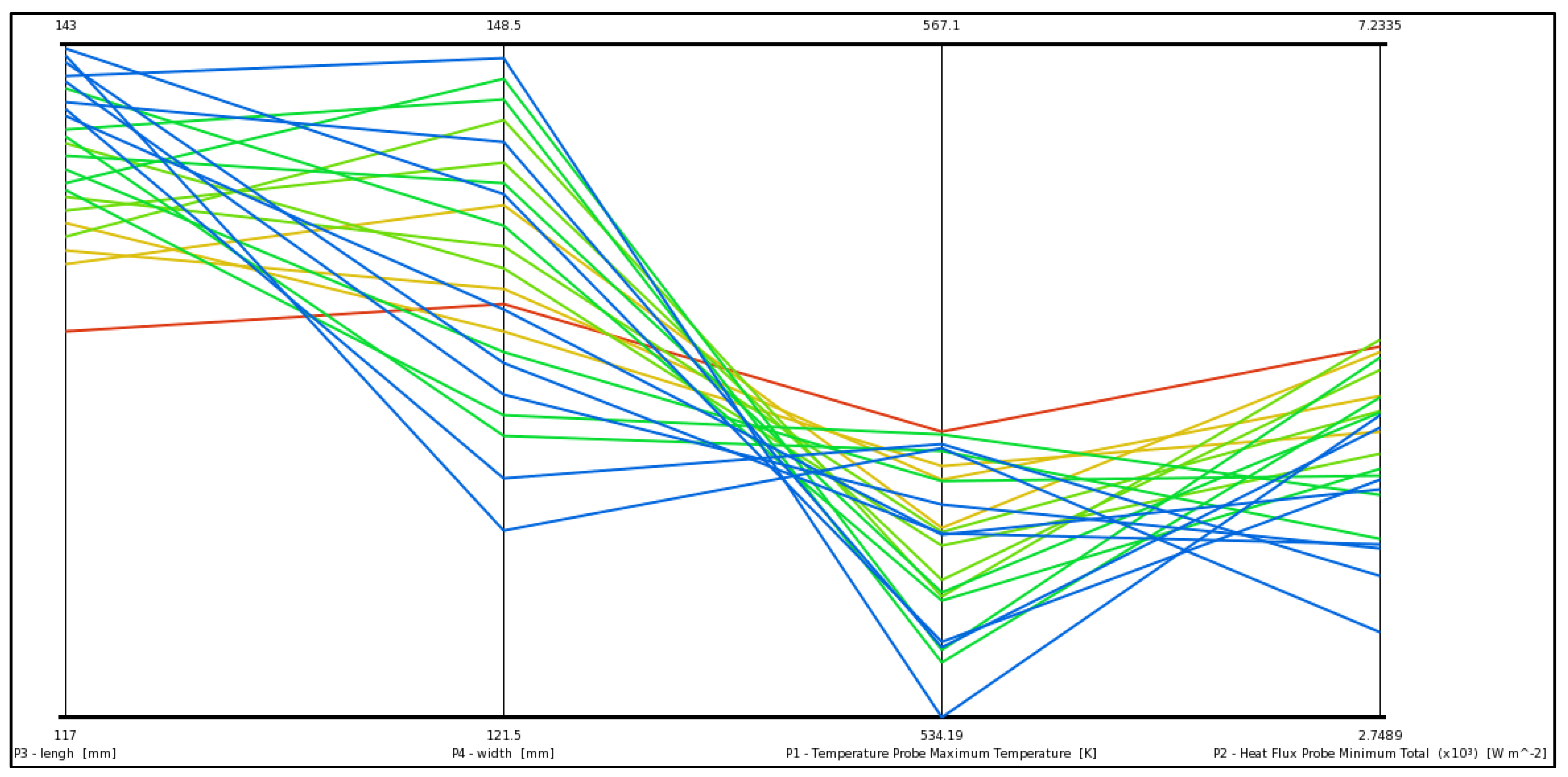
3.4.2. Trade-Off Analysis

Nevertheless, beyond a threshold fin size, no additional benefit was observed from further increases in fin size, indicative of the necessity for careful fin dimension optimization. This balance is illustrated by the trade-off analysis shown in Figure 11, which shows that some designs have lower maximum temperatures, but at the expense of more heat flux. Although the design point with the lowest Tmax, 545.68 K, had a total heat flux of 5145.56 W/m2, a higher heat flux of 6319.59 W/m2 was reached, having a slightly higher Tmax of 549.46 K. This trade-off shows that the fin geometries must be optimized to meet the overall thermal efficiency without compromising the material costs involved.

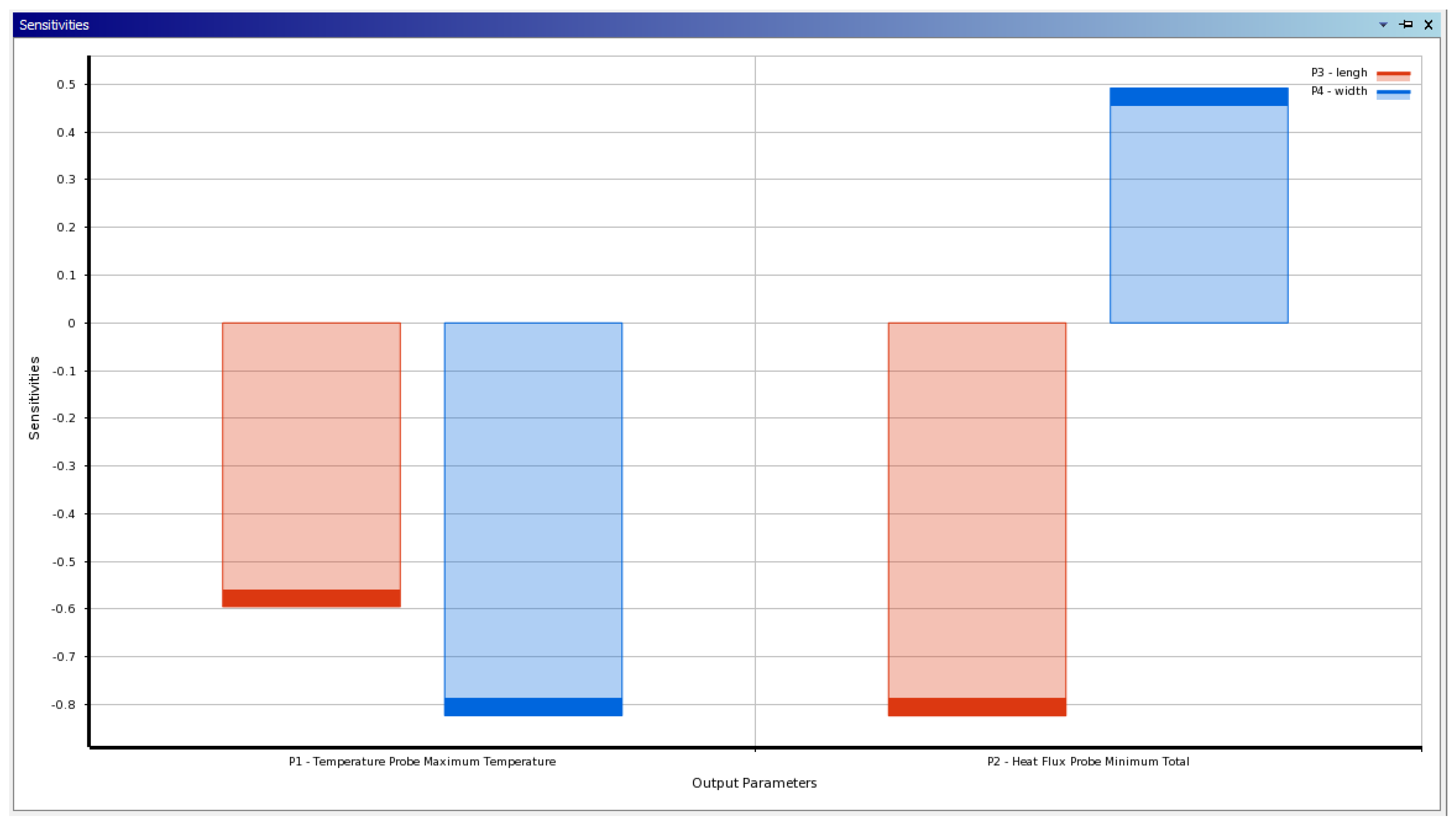
3.4.3. Sensitivity Analysis

Figure 12 shows the sensitivity analysis of the thermal performance trends of engine cylinders with respect to changes in fin length and width. The results indicate that fin length, rather than fin width, is the dominant factor in heat dissipation. This insight is especially valuable for future designs aimed at enhanced thermal efficiency and suggests that during the design, to meet thermal performance objectives, designers should focus on optimizing the fin length and adjust the width accordingly.

3.5. Critical Factors Influencing Performance

3.5.1. Mesh Quality and Element Selection

The thermal interactions within the model are accurately captured by the quality of the mesh. The cylinder model was discretized using 84,569 hexahedral elements and 100,259 nodes. With a growth rate of 1.4 and a transition ratio of 0.275, this configuration was sufficient to allow the mesh to accurately reflect the thermal gradients especially close to the internal walls of the cylinder and the bases of the fins. The current mesh proved to be reliable, but refining mesh around fin edges could improve precision in thermal characteristics in future studies.

3.5.2. Material Considerations

The choice of the fin material, cast iron, is based on its great thermal conductivity and durability. Nevertheless, its weight could be a disadvantage for this material. An approach with better thermal performance, yet reduced weight, can be found in alternatives such as aluminum alloys or lightweight composites [43]. The future research could optimize these materials for improved heat transfer while reducing weight.

3.5.3. Boundary Conditions

The boundary conditions applied in this study simulated typical engine operating conditions, where the inner cylinder surface experiences elevated temperatures due to combustion, while the fins undergo convective heat transfer to the atmosphere. Although these conditions provide valuable insights, real engine scenarios may involve more dynamic and transient conditions. Subsequent studies should incorporate transient thermal testing to better reflect practical usage.

3.5.4. Design and Manufacturing Constraints

While the current fin design demonstrates effective heat dissipation, it is crucial to consider manufacturing feasibility. Complex geometries may lead to increased production costs and challenges in maintaining structural integrity [44]. Future designs should optimize thermal performance while considering manufacturability and robustness, potentially utilizing multi-objective optimization strategies to achieve this balance. Figure 13 provides a summary of the key results, including the modeling errors and variations from the reference.
These “Variation from Reference” columns summarize deviations of measured values from the optimal reference values. It maintains adequate heat flux with minor adjustments to the model as geometric change takes place. The minimal errors indicate that precision-critical applications require continuous monitoring, while the optimization balances dimensional constraints and performance. Fin design can be changed slightly to improve or degrade heat dissipation without much effect on temperature. Candidate 1 is most balanced, with the closest match to reference values for applications that are most concerned with thermal efficiency and design adherence. Candidates 2 and 3 show slightly larger maximum temperatures, which indicates that small design variations affect thermal performance and highlight the sensitivity of the design to the best performance.

3.6. Comparative Analysis

The findings of this study corroborate previous research on finned heat exchangers, which emphasizes the significant influence of fin length and area on heat removal efficiency. This alignment with the existing literature enhances the credibility of the results. Comparative analysis with the work of Sonawane et al. [45] illustrates that variations in fin pitch and thickness also impact thermal characteristics. The quantitative variations in heat flux and temperature distribution reflect the differences in material properties and simulation parameters used in this study. The research produced two design prototypes: a generic design with dimensions of 117.13 mm in length and 121.635 mm in width, yielding a heat flux of 5740.22 W/m2; and an optimized design, which measures 118.95 mm in length and 145.26 mm in width, with a resulting heat flux of 7225.31 W/m2. Table 5 illustrates the potential for significant improvements in thermal performance in terms of optimized fin geometry.

4. Discussion

Results from the engine cylinder fin optimization were in good agreement with the initial hypothesis and expectations. The substantiation of the premise that systematic optimization can afford large thermal benefits is supported by the substantial increase in the heat dissipation capacity, especially the 25.87% improvement observed in the optimized fin design. The careful fin dimensioning and the use of advanced computational techniques permitted more efficient design than methods used prior to this enhancement. The findings of the heat dissipation distribution, specifically the lower heat transfer at fin tips, were anticipated and point to additional refinement in the areas. These results maintain consistency with previous studies, lending support for utilizing direct optimization techniques in the pursuit of enhancing thermal performance in engine applications.

5. Conclusions

The comprehensive finite element analysis (FEA) in this study successfully validates our initial hypothesis that heat dissipation efficiency in the engine cooling system can be improved significantly by optimizing fin geometry. Key questions underlying the research were the influence of fin design on thermal performance and potential trade-offs associated with increasing heat transfer rates and decreasing temperatures inside the engine cylinder. The findings revealed several critical insights:
  • Optimization of fin geometry: The optimization process demonstrated a clear correlation between fin dimensions—specifically length and width—and thermal performance metrics such as maximum temperature and total heat flux. The optimized design measured 118.95 mm in length and 145.26 mm in width and had a capacity for heat dissipation of 7225.31 W/m2, which is 25.87% higher than the capacity of the generic design, 5740.22 W/m2. This enhancement underscores the potential for significant improvements in engine cooling efficiency through targeted geometric modifications.
  • Heat transfer characteristics: The analysis indicates that while the fins effectively dissipated heat, the heat flux was notably lower near the fin tips. These findings suggest further refinement of fin geometry or study of alternative materials having better thermal conductivity to realize higher heat flux density overall.
  • Importance of material selection: The study used cast iron, which has good thermal properties and the work demonstrated the feasibility of lighter materials or high-conductivity alloys to obtain improved performance. This consideration is particularly relevant to automotive and aerospace applications owing to weight reduction constraints while maintaining thermal efficiency.
  • Despite these substantial findings, certain limitations were recognized in the study:
  • The reliance on steady-state thermal analysis presents a limitation, as it does not account for the transient heat transfer characteristics inherent in real engine operations under varying loads. This factor may affect fin performance differently depending on changes in engine temperatures during operation, which are not considered in the steady-state model presented here. The potential modeling errors may arise due to assumptions in material properties, boundary conditions, and simplified geometries. Variations in the mesh resolution and external environmental factors may also influence the accuracy of the results.
  • The FEA results provide useful information but also indicate the significance of experimental validation. Additional dynamics of fin performance could be found in real-world conditions (such as workflow variations, manufacturing defects, and material behavior under operational stress). In the future, transient heat analysis and experimental studies should be incorporated into research to more fully understand the fin efficiency in engine cooling systems.
Although the present fin design can be effective at heat dissipation, additional optimization is required for improved performance, especially at fin tip locations that have less effective heat transfer. Designs for future projects should pursue fin dimensions where an appropriate balance exists between thermal optimum properties and material cost efficiency. The present fin design is suitable for effective heat dissipation; however, optimization is necessary to enhance performance, particularly in regions such as fin tips where heat transfer is less efficient. These results provide a robust starting point for the application of these designs and efficiencies for cooling systems in automotive, aerospace, and heavy machinery applications that rely heavily on efficient heat transfer for keeping systems operating and performing. This research contributes to a growing field of knowledge aimed at improving engine performance and sustainability by continuing to uncover the complexities of fin design and thermal management.

Author Contributions

Conceptualization, A.A. and M.O.D.; methodology, M.I.; software, A.A.; validation, M.I., A.A. and M.O.D.; formal analysis, A.A.; investigation, A.A.; resources, M.O.D.; data curation, M.I., A.A. and M.O.D.; writing—original draft preparation, A.A.; writing—review and editing, M.I. and M.O.D.; visualization, M.I.; supervision, A.A.; project administration, M.I.; funding acquisition, M.O.D. All authors have read and agreed to the published version of the manuscript.

Funding

The APC was funded by the University of Johannesburg.

Data Availability Statement

All relevant data and results are presented within this manuscript.

Conflicts of Interest

The authors declare no conflicts of interest.

Abbreviations

FObjective function to be minimized or maximized.
TmaxMaximum temperature at specific points on the fin surface.
TrefReference temperature.
QTotal heat flux across the surface.
qrefReference heat flux.
α and βWeighting factors used to balance the objectives of temperature reduction and heat dissipation.

References

  1. Agarwal, A.; Pitso, I. Modelling & Numerical Exploration of Pulsejet Engine Using Eddy Dissipation Combustion Model. Mater. Today Proc. 2020, 27, 1341–1349. [Google Scholar] [CrossRef]
  2. Chen, W.; Yang, X.; Zuo, Q.; Wang, H.; Ning, D.; Kou, C.; Zhang, Y.; Zhu, G. Combustion Characteristics and Performance Analysis of a Heavy-Fuel Rotary Engine by Designing Fuel Injection Position. Appl. Therm. Eng. 2024, 247, 123021. [Google Scholar] [CrossRef]
  3. Förster, F.; Crua, C.; Davy, M.; Ewart, P. Temperature Measurements under Diesel Engine Conditions Using Laser Induced Grating Spectroscopy. Combust. Flame 2019, 199, 249–257. [Google Scholar] [CrossRef]
  4. Lu, B.; Zhang, Z.; Cai, J.; Wang, W.; Ju, X.; Xu, Y.; Lu, X.; Tian, H.; Shi, L.; Shu, G. Integrating Engine Thermal Management into Waste Heat Recovery under Steady-State Design and Dynamic off-Design Conditions. Energy 2023, 272, 127145. [Google Scholar] [CrossRef]
  5. Sachar, S.; Parvez, Y.; Khurana, T.; Chaubey, H. Heat Transfer Enhancement of the Air-Cooled Engine Fins through Geometrical and Material Analysis: A Review. Mater. Today Proc. 2023. [Google Scholar] [CrossRef]
  6. Mert Cuce, P.; Cuce, E. Optimization of Configurations to Enhance Heat Transfer from a Longitudinal Fin Exposed to Natural Convection and Radiation. Int. J. Low-Carbon Technol. 2014, 9, 305–310. [Google Scholar] [CrossRef]
  7. Subbiah, M.; Balamurugan, S.; Jayakumar, K.; Karthick, R. Analysis of Engine Cylinder Block with Fins by Varying Different Materials. Mater. Today Proc. 2023, 72, 2039–2043. [Google Scholar] [CrossRef]
  8. Durgam, S.; Kale, A.; Kene, N.; Khedkar, A.; Palve, S.; Gawai, N.M. Thermal Analysis of Fin Materials for Engine Cylinder Heat Transfer Enhancement. IOP Conf. Ser. Mater. Sci. Eng. 2021, 1126, 012071. [Google Scholar] [CrossRef]
  9. Kadam, S.S.; Umale, S. Effect of Various Fin Geometries on Heat Dissipation of Traction Motors Used in Electric Vehicles. J. Phys. Conf. Ser. 2021, 2007, 012021. [Google Scholar] [CrossRef]
  10. Jones, D.R.; Martins, J.R.R.A. The DIRECT Algorithm: 25 Years Later. J. Glob. Optim. 2021, 79, 521–566. [Google Scholar] [CrossRef]
  11. Babu, G. Heat Transfer Analysis and Optimization of Engine Cylinder Fins of Varying Geometry and Material. IOSR J. Mech. Civ. Eng. 2013, 7, 24–29. [Google Scholar] [CrossRef]
  12. Angamuthu, K.; Krishnan, G.; Gowrishankar, M.; Abraham, J.G. Modeling and Simulation Studies of 100 cc Motor Cycle Engine Cylinder with Groove and Perforated Fin Design Using Different Materials. Mater. Today Proc. 2021, 42, 1447–1455. [Google Scholar] [CrossRef]
  13. Mahek, M.K.; Al-Aribe, K.M. Heat Transfer Enhancement in Stirling Engines Using Fins with Different Configurations. In Proceedings of the 2022 Advances in Science and Engineering Technology International Conferences (ASET), Dubai, United Arab Emirates, 21–24 February 2022; pp. 1–6. [Google Scholar]
  14. Avinash Kapil, S.; Rameshvamsi, C.O.; Vishal Varma, V. Design and Analysis on Engine Cylinder Fins for Variable Materials. Int. J. Mod. Trends Sci. Technol. 2021, 7, 157–162. [Google Scholar]
  15. Dobzhanskyi, O.; Narumanchi, S.; Tomerlin, J.; Kekelia, B.; Gouws, R.; Cousineau, E. Modelling a Motor Cooling System with Stator Lamination Fins. In Proceedings of the 2023 IEEE 64th International Scientific Conference on Power and Electrical Engineering of Riga Technical University (RTUCON), Riga, Latvia, 9–11 October 2023; pp. 1–5. [Google Scholar]
  16. Saxena, D.; Chourasia, A.; Dwivedi, S.; Mahore, S. Study and Optimization of Heat Transfer Analysis for Engine Fins Using Ansys. Int. J. Sci. Res. Comput. Sci. Eng. 2019, 7, 22–32. [Google Scholar] [CrossRef]
  17. Shareef, S.K.M.; Vikas, M.S.; Kumar, A.L.N.A.; Dasore, A.; Chhalotre, S.; Rajak, U.; Nath Verma, T. Design and Thermal Analysis of Engine Cylinder Fin Body Using Various Fin Profiles. Mater. Today Proc. 2021, 47, 5776–5780. [Google Scholar] [CrossRef]
  18. Agarwal, A.; Letsatsi, M.T. Investigation of the Effect of Engine Cylinder Fin Shape on Heat Transfer Characteristics Under Forced Convection. In Emerging Trends in Mechanical and Industrial Engineering: Select Proceedings of ICETMIE 2022; Springer: Berlin/Heidelberg, Germany, 2023; pp. 113–128. [Google Scholar]
  19. Khan, S.; Chourasia, B.K. Steady State Thermal Analysis of Cylinder Fins with Varied Materials and Thicknesses. Int. J. Res. Appl. Sci. Eng. Technol. 2023, 11, 915–933. [Google Scholar] [CrossRef]
  20. Chaitanya, P.S.; Suneela Rani, B.; Kumar, K.V. Thermal Analysis of Engine Cylinder Fin by Varying Its Geometry and Material. IOSR J. Mech. Civ. Eng. 2014, 11, 37–44. [Google Scholar] [CrossRef]
  21. Gupta, S.; Kumar, D.; Kumar, S. Heat Transfer Analysis of Engine Cylinder Fins by Varying Geometry. Int. J. Res. Publ. Rev. 2022, 3, 969–981. [Google Scholar]
  22. Kumaravelu, T.; Saadon, S.; Abu Talib, A.R. Heat Transfer Enhancement of a Stirling Engine by Using Fins Attachment in an Energy Recovery System. Energy 2022, 239, 121881. [Google Scholar] [CrossRef]
  23. Ocłoń, P.; Łopata, S.; Stelmach, T.; Li, M.; Zhang, J.-F.; Mzad, H.; Tao, W.-Q. Design Optimization of a High-Temperature Fin-and-Tube Heat Exchanger Manifold—A Case Study. Energy 2021, 215, 119059. [Google Scholar] [CrossRef]
  24. Varghese, S.Z.; Paul, B.; Roy, S.M.; John, K. Heuristic Technique for Multi-Objective Optimisation of Engine Cylinder Fins. Mater. Today Proc. 2022, 58, 80–85. [Google Scholar] [CrossRef]
  25. Godi, N.Y. Thermal Performance Maximisation in a Complex Heat Exchanger with Solid and Hollow Cylindrical Fins. Int. Commun. Heat Mass Transf. 2024, 152, 107286. [Google Scholar] [CrossRef]
  26. Dahham, R.Y.; Wei, H.; Pan, J. Improving Thermal Efficiency of Internal Combustion Engines: Recent Progress and Remaining Challenges. Energies 2022, 15, 6222. [Google Scholar] [CrossRef]
  27. Dev, S.; Guo, H.; Liko, B. A Study on the High Load Operation of a Natural Gas-Diesel Dual-Fuel Engine. Front. Mech. Eng. 2020, 6, 545416. [Google Scholar] [CrossRef]
  28. Zaccardi, J.-M.; Pagot, A.; Vangraefschepe, F.; Dognin, C.; Mokhtari, S. Optimal Design for a Highly Downsized Gasoline Engine. In SAE Technical Paper 2009-01-1794; SAE International: Warrendale, PA, USA, 2009. [Google Scholar]
  29. Agarwal, A.; Cavicchioli Batista, R.; Gurung, A. Analyzing the Impact of Bumper Height on Pedestrian Injuries Using Explicit Dynamics. In Smart Electric and Hybrid Vehicles; CRC Press: New York, NY, USA, 2024; pp. 57–89. [Google Scholar]
  30. Sagar, P.; Teotia, P.; Sahlot, A.D.; Thakur, H.C. Heat Transfer Analysis and Optimization of Engine Fins of Varying Surface Roughness. Mater. Today Proc. 2017, 4, 8565–8570. [Google Scholar] [CrossRef]
  31. Kang, Y.J.; Pandey, S.; Park, S.I.; Kim, Y.S.; Wie, J.H.; Kim, D.H.; Ha, M.Y. Comprehensive Analysis and Design Optimization of Temperature Distribution in Radiant Heaters for Cooking Applications. Case Stud. Therm. Eng. 2023, 52, 103687. [Google Scholar] [CrossRef]
  32. Boz, Z.; Erdogdu, F.; Tutar, M. Effects of Mesh Refinement, Time Step Size and Numerical Scheme on the Computational Modeling of Temperature Evolution during Natural-Convection Heating. J. Food Eng. 2014, 123, 8–16. [Google Scholar] [CrossRef]
  33. Huang, G.-J.; Wong, S.-C.; Lin, C.-P. Enhancement of Natural Convection Heat Transfer from Horizontal Rectangular Fin Arrays with Perforations in Fin Base. Int. J. Therm. Sci. 2014, 84, 164–174. [Google Scholar] [CrossRef]
  34. Armstead, J.R.; Miers, S.A. Review of Waste Heat Recovery Mechanisms for Internal Combustion Engines. J. Therm. Sci. Eng. Appl. 2014, 6, 014001. [Google Scholar] [CrossRef]
  35. Fakhari, S.M.; Mrad, H. Aerodynamic Shape Optimization of NACA Airfoils Based on a Novel Unconstrained Conjugate Gradient Algorithm. J. Eng. Res. 2024, in press. [Google Scholar] [CrossRef]
  36. Agarwal, A.; Rimal, A.; Ilunga, M. Non-Linear Contact Analysis and Response Surface Optimization of Railway Wheel Using ANSYS. Math. Model. Eng. Probl. 2024, 11, 2039–2047. [Google Scholar] [CrossRef]
  37. Jikol, F.; Akop, M.Z.; Arifin, Y.M.; Salim, M.A.; Herawan, S.G. A Study of Steady-State Thermal Distribution on Circular Plate Using ANSYS. Int. J. Nanoelectrics Mater. 2021, 14, 479–488. [Google Scholar]
  38. Agarwal, A.; Letsatsi, M.T.; Pitso, I. Response Surface Optimization of Heat Sink Used in Electronic Cooling Applications. In Recent Advances in Materials and Modern Manufacturing: Select Proceedings of ICAMMM 2021; Springer: Berlin/Heidelberg, Germany, 2022; pp. 121–129. [Google Scholar]
  39. Chavan, V.U.; Guruvasanth, A.S.; Rana, A.; Prabu, S.S. Comparative Study on Thermal Analysis of Disc Brake Using ANSYS Simulation. ECS Trans. 2022, 107, 15693–15700. [Google Scholar] [CrossRef]
  40. Agarwal, A.; Molwane, O.B.; Letsatsi, M.T. Experimental Investigation & Analysis of Heat Transfer Characteristics in Automotive MMC Disc Brake Under Steady State and Dynamic Conditions. J. Eng. Res. 2021, 9, 1–12. [Google Scholar] [CrossRef]
  41. Sun, X.; Zhuang, Y.; Liu, L.; Dong, Y.; Zhang, L.; Du, J. Multi-Objective Optimization of Heat Exchange Network and Thermodynamic Cycles Integrated System for Cooling and Power Cogeneration. Appl. Energy 2022, 321, 119366. [Google Scholar] [CrossRef]
  42. Gupta, D.; Saha, P.; Roy, S. Multi-Objective Optimization of the Perforated Micro Pin-Fin Heat Sink Using Non-Dominated Sorting Genetic Algorithm-II Coupled with Computational Fluid Dynamics Simulation. J. Heat Transfer. 2022, 144, 093301. [Google Scholar] [CrossRef]
  43. Zhang, W.; Xu, J. Advanced Lightweight Materials for Automobiles: A Review. Mater. Des. 2022, 221, 110994. [Google Scholar] [CrossRef]
  44. Agarwal, A.; Mthembu, L. Comparative Analysis of Boron-Al Metal Matix Composite and Aluminum Alloy in Enhancing Dynamic Performance of Vertical-Axis Wind Turbine. Processes 2024, 12, 2288. [Google Scholar] [CrossRef]
  45. Sonawane, C.R.; Rath, P.; Vats, N.; Patekar, S.; Verma, P.; Pandey, A. Numerical Simulation to Evaluate the Thermal Performance of Engine Cylinder Fins: Effect of Fin Geometry and Fin Material. Mater. Today Proc. 2022, 49, 1590–1598. [Google Scholar] [CrossRef]
Figure 1. Automobile fin [7].
Processes 12 02659 g001
Figure 2. CAD model of the engine cylinder with fins.
Processes 12 02659 g002
Figure 3. Meshed model of an engine cylinder with fins.
Processes 12 02659 g003
Figure 4. Thermal loading conditions.
Processes 12 02659 g004
Figure 5. Temperature distribution plot across fins.
Processes 12 02659 g005
Figure 6. Total heat flux of engine cylinder with fins.
Processes 12 02659 g006
Figure 7. Total heat flux vector plot of the engine cylinder with fins.
Processes 12 02659 g007
Figure 8. Samples chart.
Processes 12 02659 g008
Figure 9. Candidate points chart.
Processes 12 02659 g009
Figure 10. Optimized design points.
Processes 12 02659 g010
Figure 11. Trade-off chart.
Processes 12 02659 g011
Figure 12. Sensitivity percentage comparison.
Processes 12 02659 g012
Figure 13. Variation from reference.
Processes 12 02659 g013
Table 1. Engine block specification [17].
ParameterValue
Stroke49.5 mm
Bore50 mm
No. of fins6
Fin pitch (mm)7
Fin thickness (mm)3
Fin materialCast iron
Table 2. Grid independence test.
Number of ElementsTemperature (K)
81,546305.1
82,145306.4
83,549306.5
84,256307.8
84,569307.8
Table 3. Direct optimization definition.
Optimization Study
Minimize P1; P1 <= 549 kGoal, minimize P1 (default importance); strict constraint, P1 values less than or equals to 549 K (default importance)
Minimize P2; P2 <= 5300 W/m2Goal, minimize P2 (default importance); strict constraint, P2 values less than or equals to 5300 W/m2 (default importance)
Maximize P3Goal, maximize P3 (default importance)
Maximize P4Goal, maximize P4 (default importance)
Table 4. Optimization points generated.
Design PointP3-Length (mm) P4-Width (mm) P1-Temperature Probe Maximum Temperature (K)P2-Heat Flux Probe Minimum Total (W/m2)
1117.13121.635567.08997195740.224301
2117.39135.135557.27380986969.619151
3117.65128.385562.3618536390.156727
4117.91141.885551.34775397233.406658
5118.17125.01564.49323125962.532627
6118.43138.51554.10004277005.728446
7118.69131.76559.45093386529.746769
8118.95145.26547.95783087225.314662
9119.21123.3225565.14450685606.025618
10119.47136.8225555.12933966765.61932
11119.73130.0725560.29425666224.146702
12119.99143.5725549.12705087028.968602
13120.25126.6975562.46234745810.567217
14120.51140.1975551.89472056819.6902
15120.77133.4475557.31098026353.461488
16121.03146.9475545.68588877018.54887
17121.29122.47875564.70889895182.492672
18121.55135.97875554.98605966431.141529
19121.81129.22875559.99613045837.584318
20122.07142.72875549.09323736736.400213
21122.33125.85375562.06613775409.426697
22122.59139.35375551.77869266498.572212
23122.85132.60375557.04733895990.671368
24123.11146.10375545.67279666734.215435
25123.37124.16625562.63663335070.445399
26123.63137.66625552.72485966242.656236
27123.89130.91625557.8079595696.35007
28124.15144.41625546.76044316541.721514
29124.41127.54125559.912975294.350943
30124.67141.04125549.4599676319.591139
31124.93134.29125554.79047245833.608594
32125.19147.79125543.2923956550.565582
33125.45122.05687562.80969854523.352965
34125.71135.55687553.43656015824.17605
35125.97128.80687558.24759525195.91973
36126.23142.30687547.6787176188.668439
37126.49125.43187560.18836064772.796432
38126.75138.93187550.24548955922.780754
39127.01132.18187555.31925055362.855782
40127.27145.68187544.27033086218.651307
41127.53123.74437560.63986824437.160012
42127.79137.24437551.07868045666.833954
43128.05130.49437555.96329355077.768478
44128.31143.99437545.25021976024.683051
45128.57127.11937557.9399784665.187214
46128.83140.61937547.83206795772.503137
47129.09133.86937552.96842045246.437272
48129.35147.36937541.79636236066.769987
49129.61122.90062559.89942024064.157068
50129.87136.40062550.63681645351.727535
51130.13129.65062555.36331794730.951224
52130.39143.15062544.92593995736.147703
53130.65126.27562557.24277344312.210891
54130.91139.77562547.4234075467.564964
55131.17133.02562552.40744634906.922827
56131.43146.52562541.49948735786.779727
57131.69124.58812557.61987924012.067467
58131.95138.08812548.17780155222.592291
59132.21131.33812552.97449344621.83869
60132.47144.83812542.40054935587.637089
61132.73127.96312554.88907474242.300543
62132.99141.46312544.91223755330.447908
63133.25134.71312549.95618294802.859318
64133.51148.21312538.93216555642.574958
65133.77121.8459557.80234383473.322464
66134.03135.3459549.02121584764.084053
67134.29128.5959553.48639534120.3156
68134.55142.0959543.50638435189.862581
69134.81125.2209555.20612183723.137789
70135.07138.7209545.85761114896.003902
71135.33131.9709550.58719484317.732674
72135.59145.4709540.12286995267.76048
73135.85123.5334555.45310063439.519901
74136.11137.0334546.48798224657.310405
75136.37130.2834551.0267094053.495899
76136.63143.7834540.90549325072.047784
77136.89126.9084552.78388063674.591077
78137.15140.4084543.27350464793.554788
79137.41133.6584548.0658024233.895729
80137.67147.1584537.48123785150.085797
81137.93122.6896554.42746583145.558231
82138.19136.1896545.76138924361.00811
83138.45129.4396550.14185183757.250785
84138.71142.9396540.30264894787.572671
85138.97126.0646551.80496833383.136113
86139.23139.5646542.58563844512.958036
87139.49132.8146547.22449343947.428553
88139.75146.3146536.91217654883.55314
89140.01124.3771551.9868533114.801354
90140.27137.8771543.14404914270.544368
91140.53131.1271547.59525153698.249939
92140.79144.6271537.62161874682.196593
93141.05127.7521549.29508063345.591707
94141.31141.2521539.92062994407.400711
95141.57134.5021544.62024543875.893848
96141.83148.0021534.19367074766.812185
97142.09122.26781551.50430912748.905208
98142.35135.76781543.1942813911.140046
99142.61129.01781547.3747623316.911719
100142.87142.5178537.89111944339.659693
Table 5. Design type comparative analysis.
Design GeneticLength (mm)Width (mm)Heat Flux (W/m2)
Generic design 117.13121.6355740.2243
Optimized design (mathematical model)118.95145.267225.31 W/m2
Disclaimer/Publisher’s Note: The statements, opinions and data contained in all publications are solely those of the individual author(s) and contributor(s) and not of MDPI and/or the editor(s). MDPI and/or the editor(s) disclaim responsibility for any injury to people or property resulting from any ideas, methods, instructions or products referred to in the content.

