1. Introduction
With the implementation of the oil and gas resource development strategy of “stabilizing the east, developing the west, preparing for the south, and exploring overseas”, the number of deep and ultra-deep wells in the new and old exploration areas has been increasing year by year, and the depth index has risen rapidly. PetroChina has drilled more than 30 deep wells with an annual depth of over 8000 m, among which the most bottomless vertical well, Peng Shen 6 in the Southwest oil and gas field, has exceeded 9000 m in vertical depth. Well Take 1, the first ultra-deep well with a depth of 10,000 m in China, was drilled in Tarim Basin on 1 May 2023, with a designed depth of 11,000 m. In the process of drilling, there are world-class problems such as a low drilling speed in deep high-grinding formations, a harsh downhole ultra-high temperature and ultra-high pressure environment, as well as extremely complex geological conditions, which seriously affect the efficiency and safety of drilling construction. The drilling cycle is longer and the daily footage is less and less. The acceleration of deep and ultra-deep well drilling has gradually become the focus of attention for experts and scholars. To improve the drilling speed of deep wells, researchers have developed various speed-up tools, mainly including downhole power drilling tools, rotary impact drilling tools, downhole pulse cavitation jet generation devices, downhole torque impact drilling tools, etc. [
1,
2,
3,
4]. Analysis has found that although the acceleration mechanisms of the above tools are different, there is a commonality: the energy sources for the tools to work all come from the drilling circulating medium. In the drilling process of deep and ultra-deep wells, the circulating pressure consumption of drilling fluid increases with the increase in good depth. In ultra-deep wells, limited by surface pump pressure conditions, there may even be situations where the circulating medium can only meet the requirements of circulating rock carrying. Therefore, the working status of the tools mentioned above, or devices, will be significantly affected, and there is a high possibility that they may not work or even affect the progress of drilling operations; this limits their application in deep and ultra-deep wells. Finding new underground energy and developing new acceleration technologies and equipment have become the key to improving the deep well drilling speed. It is worth noting that in the field of drill string dynamics research, it has been found that the vibration phenomenon of the drill string is a complex problem often encountered in vertical well drilling. It affects the construction efficiency of drilling and frequently and violently causes accidents such as fatigue fracture and damage to the drill string, thereby increasing construction costs and leading to significant economic losses. The existing methods for reducing drill string vibration are to use shock absorbers to convert the vibration energy into the elastic potential energy and internal energy of hydraulic oil or to release the friction energy between the springs inside the shock absorber. This wastes energy and generates heat that affects the performance of downhole tools. Given the above factors, the authors propose the concept of using drill string vibration to achieve deep good acceleration and design a vibration reduction and energy enhancement device for the bottom hole drill string to apply this destructive energy to the field of deep good acceleration to achieve breakthroughs in the field of deep good acceleration.
2. Research on the Basic Characteristics and Laws of Longitudinal Vibration of Drill String
Based on the principle of similarity, a dynamic research experimental device for the bottom drill string was designed (
Figure 1), which can test the influence of various constraint parameters on the vibration characteristics of the drill string and study the impact of parameters such as rotational speed, drilling pressure, drilling tool combination, drilling tool wellbore size matching, as well as vibration reduction and pressure boosting device principle prototype elasticity and damping coefficient on the vibration characteristics of the drill string. The BHA motion state simulation experimental device is a steel truss structure, with an overall height of 15 m and an effective height of 13 m. It consists of a vertical wellbore and an inclined branch. The inclined branch has a length of 8.0 m and the well deviation angle can be adjusted within 5°. Among them, there are three types of sensors, namely the eddy current displacement sensor (model ST-1, measurement range: 0–12 mm, linear voltage output: 0–5 V, sensitivity: 0.8 V/mm), the strain gauge tension (compression) force sensor (BK-3, measurement range: 0–5 kg, sensitivity: 1–2 mV/V, non-linearity: 0.1% FS), and the piezoelectric force sensor (model YD25-A, measurement range: 0–100 N, sensitivity: 400 pC/N, frequency: 1–10,000 Hz). Based on this experimental device, a study was conducted on the motion and force testing of the bottom hole drill string under different working conditions using a pendulum drilling tool combination [
5,
6,
7,
8].
The representative test results of drill string combinations are shown in
Figure 2.
BHA prototype for experimental research: 311 mmBIT + 228.6 mmDC × 2 pieces + 310 mm SST + 228.6 mmDC × 4 + 203.2 mmDC × 6 pieces + 127 mmDP.
From
Figure 2a, it can be concluded that with a set speed of 69.0 r/min and an applied drilling pressure of 178.9 kN (1 kN/m
2 = 1 kPa), when the confidence interval is 90%, the fluctuation range of the drilling pressure is 136.1 to 220.3 kN. When the confidence interval is 80%, the fluctuation range of the drilling pressure is 145.2~211.1 kN, and the measured average drilling pressure is 179.3 kN.
From
Figure 2b, it can be concluded that the set speed is 92.0 r/min, and a drilling pressure of 178.9 kN is applied. When the confidence interval is 90%, the fluctuation range of the drilling pressure is 105.0~210.4 kN. When the confidence interval is 80%, the fluctuation range of the drilling pressure is 123.1~210.2 kN, and the measured average drilling pressure is 168.5 kN.
From
Figure 2c, it can be concluded that the set speed is 115.0 r/min, and a drilling pressure of 178.9 kN is applied. When the confidence interval is 90%, the fluctuation range of the drilling pressure is 80.1 to 236.8 kN. When the confidence interval is 80%, the fluctuation range of the drilling pressure is 101.2~218.5 kN, and the measured average drilling pressure is 160.3 kN.
Based on the above analysis, the following conclusion can be drawn: for the 311.1 mm wellbore, 228.6 mm drill collars, and pendulum drilling tools, when the applied drilling pressure is 178.9 kN, and the rotation speed varies between 69 and 115 r/min, the actual fluctuation value of the drilling pressure is between 80.1 and 236.8 kN. Meanwhile, analysis of the above figures also reveals that the fluctuation frequency is about 3–4 times the rotational speed. Similarly, indoor experimental research has found that for a 244.5 mm wellbore, 177.8 mm drill collars, and pendulum drilling tools, when the applied drilling pressure is 134.2 kN and the rotation speed varies between 70 and 120 r/min, the actual drilling pressure wave momentum is between 10 and 150 kN, and the fluctuation frequency is also 3–4 times the rotation speed. This is in good agreement with the underground measurement results in the literature.
Experimental research and previous on-site testing results have shown that during the drilling process, there is a high frequency and significant amplitude fluctuation in the bottom hole drilling pressure, and its fluctuation amplitude increases with the increase in the good depth. The vibration is more severe than conventional drilling, and the vibration energy of the drill string is more significant. This provides reliable power for accelerating the complex formation in deep wells. If this energy is effectively utilized, it is expected to improve the drilling speed in deep and complex formations.
3. Concept and Device for Vibration Reduction, Energy Enhancement, and Speed Increase of Bottom Hole Drill String
3.1. The Concept of Vibration Reduction, Energy Enhancement, and Speed Increase for Bottom Hole Drill String
The high-frequency and significant changes in drilling pressure directly affect the drill bit, causing the cutting teeth of the drill bit to instantly bear a powerful impact force, resulting in the collapse of the cutting teeth, leading to a slow rock-breaking drilling speed and short practical working life of the drill bit. We installed springs and damping structures in the middle of the drill string and on the upper part of the drill bit to transfer the drilling pressure to the drill bit. The fluctuation in drilling pressure will be converted into the spring’s elastic potential energy and damping work. On the one hand, the fluctuation amplitude of the drilling pressure will be significantly attenuated, and on the other hand, the working time of the impact force will be extended. Suppose the reaction of internal liquid pressure during the operation of the plunger pump structure is used as damping to attenuate drilling pressure fluctuations. In that case, the damping work can be converted into hydraulic energy of the internal liquid in the plunger pump structure, thereby increasing the liquid pressure discharged by the plunger pump. Bottom hole drilling fluid energy enhancement based on drill string vibration uses the combined action of springs and plunger pumps to attenuate drilling pressure fluctuations, transmit adequate drilling pressure, and improve liquid injection energy discharged by plunger pumps.
3.2. Bottom Hole Drill String Vibration Reduction, Energy Enhancement, and Speed Increase Device
A schematic diagram of the vibration reduction, energy enhancement, and speed increase device for the bottom hole drill string [
9,
10] is shown in
Figure 3. According to the functional units of the device, the device can be divided into a drill string linkage body and a drill string transfer body. The drill string linkage body includes a tool joint, a core shaft, and a limiting body set on the outer side of the middle of the core shaft. The drill string transfer body includes a plunger cylinder outer cylinder, a drill bit, a spline outer cylinder set on the upper part of the core shaft, and a tool center joint connected to the spline outer cylinder.
The vibration reduction and energy enhancement process of the drill string is as follows: when the drill string vibrates downwards, that is, when the drilling pressure increases, the drill string linkage body moves downward relative to the drill string transfer body, the volume in the plunger cylinder decreases, and the elastic reset element compresses and stores energy. The movement speed of the plunger head first increases and then falls. When the speed exceeds the flow rate of the drilling fluid in the plunger cylinder, the one-way valve is controlled to close. At this time, the drilling fluid in the plunger cylinder and the elastic reset element jointly share the increase in drilling pressure; the hydraulic energy of the drilling fluid in the plunger cylinder increases. When the speed is lower than the flow rate of the drilling fluid in the plunger cylinder, we control the one-way valve to open, and the drilling fluid will flow into the drill bit at normal pressure for injection. When the drill string vibrates upwards, that is, when the drilling pressure decreases, the plunger head moves upwards relative to the plunger cylinder. The elastic reset element releases energy and accelerates the tool’s reset, controls the one-way valve to open, and drilling fluid to enter the plunger cylinder. Due to the cross-sectional effect of the flow channel, the pressure inside the plunger cylinder is lower than the normal pressure. The jet with periodic increases and decreases in pressure is called a pulse jet.
The advantages of this device are [
11,
12,
13,
14,
15,
16,
17,
18,
19,
20,
21,
22,
23,
24]:
- (1)
It can effectively compress all drilling fluids at the bottom of the well periodically, transfer drilling string vibration energy, increase drilling fluid power, and achieve pulse jet modulation of the bottom hole jet with a high pulse amplitude.
- (2)
The pulse jet’s average pressure is higher than without the device, which enhances the ability to break and carry rocks and reduces the difficulty of rock fragmentation.
- (3)
The transfer of drilling string vibration energy has been achieved and effectively utilized, reducing the harm caused by drilling string vibration, effectively extending the service life of drilling tools, reducing the cost of using drilling tools, and reducing the risks of the drilling process.
- (4)
The energy source increases with the depth of the well, and the use of tools becomes more significant.
- (5)
The principle and structure of the device are simple and easy to produce, maintain, and use.
- (6)
The pulse jet generated by the vibration reduction and energy enhancement device can be applied to any drill bit. Due to the significant pulsation of the flow field at the bottom of the well, it can alleviate the mud package of the drill bit. The speed increase is essential in cases where the displacement is challenging to increase and the drilling speed is low.
3.3. Simulation of Vibration Reduction and Energy Enhancement Effect of Bottom Hole Drilling String
Simulation research was conducted to achieve the effect of downhole energy enhancement [
17,
18,
19,
20,
21,
22]. The simulation model was established based on the drilling process with a wellbore size of 215.9 mm as the prototype for simulation analysis. The drilling-related parameters in the model were set as follows: the outer diameter of the energy enhancement device was 177.8 mm; the drilling fluid flow rate Q was 0.030 m
3/s; the equivalent diameter of the drill bit nozzle was 23 mm; the pressure drop of the nozzle was 3.47 MPa. The setting of other relevant parameters in the model is as follows: the initial mass of the moving part M = 50 kg; the elastic stiffness of the flexible reset element is 50,000 N/m; the damping coefficient B is taken as 2711; take the volume elastic modulus of mud K = 1.4 × 10
9 Pa; the initial piston diameter D is taken as 100 mm; the volume inside the piston cylinder is plunger diameter D = 0.1 m; the piston area A1 is 0.007853 m
2; preliminary piston chamber volume of 0.01178 m
3; take a preliminary volume of 1 m
3 of liquid in the chamber.
The difference between the vibration energy conversion effect under deep and shallow well conditions is mainly reflected in the particularity of its hydraulic parameters (small displacement, low bit pressure drop). Taking the actual drilling hydraulic parameters of the BX1 well in Tarim Oilfield as an example for analysis and calculation, the statistical table of the hydraulic parameters of the well is shown in
Table 1 when applied in the 4000-m-deep section.
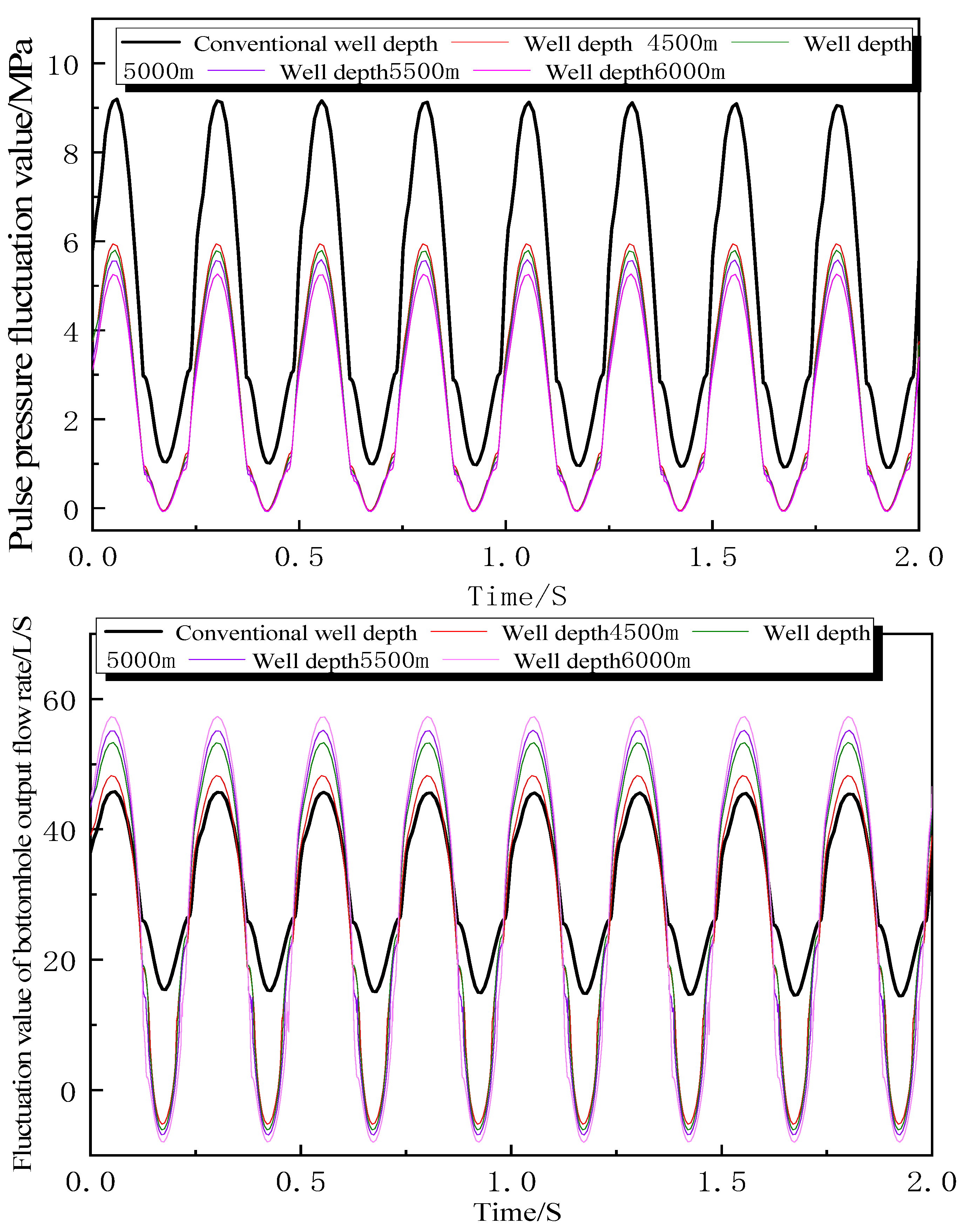
The pressure and displacement comparison curves under different well depths are shown in
Figure 3.
As shown in
Figure 4, after achieving energy conversion under deep well conditions, the maximum drill bit pressure drop generated is 4–10 times higher than that of conventional drill bits, and the maximum output displacement increases by 2–3 times. As the depth of the well increases, the fluctuation amplitude of displacement increases while the fluctuation amplitude of the pressure slightly decreases. This is because the equivalent area of the drill bit nozzle used in the deep well is relatively large. As the device discharges the port, the larger the nozzle area is, the smaller is the pressure oscillation amplitude in the hydraulic cylinder, but the fluctuation amplitude of displacement increases.
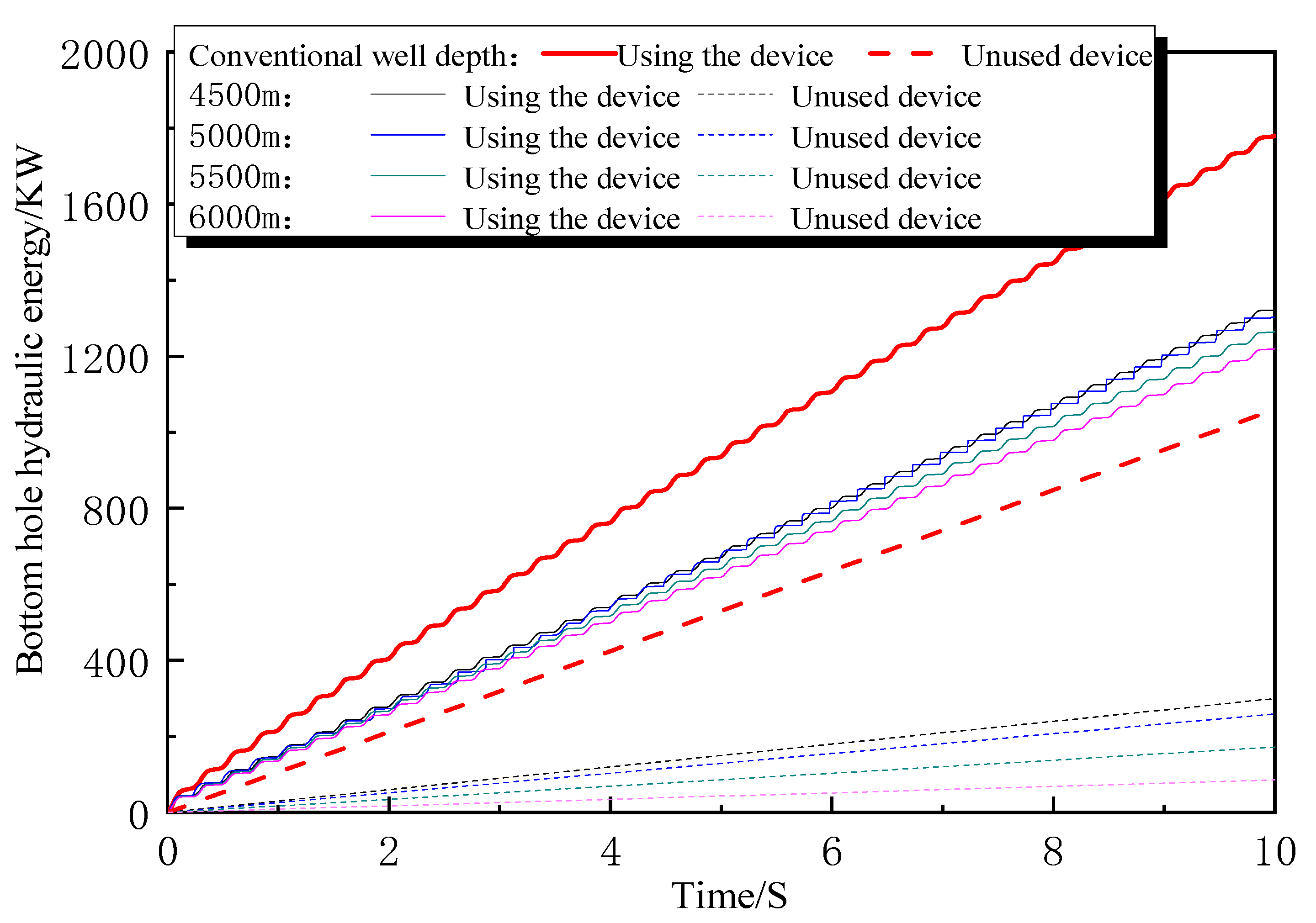
The left figure in
Figure 5 shows the variation of the hydraulic energy value at the bottom of the well with time before and after vibration energy conversion under different well depths. The correct figure shows the variation of the enhanced hydraulic energy value at the bottom of the well with good depth after achieving vibration energy conversion, as shown in the figure. After vibration energy conversion, the hydraulic energy output at the bottom of the well slightly decreases with the increase of well depth. The main reason is that the inherent hydraulic energy value at the bottom of the well before vibration energy conversion is lower (as shown by the dashed line in the left figure). However, the enhancement value of hydraulic energy at the bottom of the well has significantly increased. In shallow wells (below 4000 m), the enhancement value of hydraulic energy at the bottom of the well is 72 KJ, while in deep wells (above 4000 m), the enhancement value of hydraulic energy at the bottom of the well is above 100 KJ, when the well depth is 6000 m, the enhancement value of the hydraulic energy at the bottom of the well can reach 115 KJ. Suppose the conversion of drill string vibration energy to enhance bottom hole hydraulic energy is achieved under deep well conditions. In that case, it can effectively solve the problem of insufficient hydraulic energy at the bottom of deep wells.
4. On-Site Testing of the Acceleration Effect of Vibration Reduction and Energy Enhancement Technology for Bottom Hole Drill String
To test the application effect of the vibration reduction, energy enhancement, and speed increase device for the bottom hole drill string in improving drilling speed, field tests were conducted in the Ningtan 1H well of the Southwest Oil and Gas Field and the M502-H2 well of the Tarim Oilfield.
4.1. On-Site Testing and Analysis of Ningtan 1H Well in Southwest Oil and Gas Field
Ningtan 1H well is the first deep coal and gas exploration in the Sichuan Basin, with a designed depth of 5620 m. This well faces a series of difficulties, such as stuck drilling in the gypsum layer of the Jialingjiang Formation, leakage in the goaf of the Leiyi section (pressure coefficient of 0.4), and anti-deviation drilling. The vibration reduction, energy enhancement, and speed increase device of the bottom hole drill string are installed in the fourth section of the well (Φ A field test was conducted on a 215.9 mm wellbore (as shown in
Figure 6), using a 215.9 mm West Oil Research ZTS516 PDC drill bit + 178 mm shock-absorbing and energy enhancing tool + 431 × 411 double male joint + 172 mm West Oil Research straight screw + D212 mm stabilizer + D172 mm non-magnetic drill collar + D172 mm non-magnetic suspension + 165.1 mm drill collar two columns + bypass valve + 165.1 mm drill collar + 411 × 410 DS conversion joint + 127 mm weighted drill pipe 4 columns + 139.7 mm drill pipe. The tool was inserted into the well from 2622 m to 3246 m (due to screw replacement), with total footage of 624 m, a pure drilling time of 128 h, and an average mechanical drilling speed of 4.88 m/h (
Figure 7). Compared with the adjacent well and the same section, the average speed increased by 32.9%, and the speed improvement effect was significant. The drill bit was slightly worn after being removed, with a freshness of 90%, providing it with good protection.
The self-developed I-DAS supporting system was used to monitor the vibration during the drilling process (
Figure 8). The average drilling string vibration index of the applied well interval is 3.1, which decreased by 35.4% compared to the unused well section. There were no complex accidents such as leakage and blockage during the drilling process, and the well inclination control was reasonable (within 2.6°), with significant vibration reduction and acceleration effects.
4.2. Testing and Analysis of the Acceleration Effect of M502-H2 in Tarim Oilfield
M502-H2 well is an ultra-deepwater horizontal well in Tarim Oilfield, with a designed depth of 8780 m. The vibration reduction, energy enhancement, and speed increase device of the bottom drill string is located in the second section of the well Downhole tests were conducted on the Paleogene, Cretaceous, Jurassic, and Permian strata of the Neogene and Mesozoic in the 333.38 mm wellbore. The test well section was 1500–4024 m (the entire second section of the well), and the lithology of the test well section was mudstone, sandstone, conglomerate sandstone, and igneous rock. Drilling parameters: drilling pressure is 30–100 KN, displacement is 48–65 L/S, pump pressure is 18–25 MPa, rotational speed is 60–100 r/min, and drilling fluid density is 1.05–1.11 g/cm3. The device was installed in the second section of the well, and after hitting the cement plug and accessories, it entered a new formation for testing. The device was underground for 247 h, with a pure drilling time of 119 h and footage of 2524 m. The drilling construction of the entire section of the second section of the well was completed with an average machine speed of 21.2 m per hour.
Drilling tool assembly: Φ 333.38 PDC drill bit + Φ 228.6 mm Bottom Hole Drill String Vibration Reduction, Energy Enhancement, and Speed Enhancement Device + Φ 228.6 Drill Collars × 2 + Φ 318 mm stabilizer + Φ 177.8 mm drill collar × 18 + Φ 177.8 Drilling jar + Φ 177.8 Drill Collars × 3 + Φ 139.0 drill pipe.
According to
Table 2, it can be seen that under the same drilling parameters as neighboring wells M502, M502-H4, and M502-H6 in the same interval, M502-H2 using a bottom hole drill string vibration damping and energy-increasing speed device (increased by more than 67% compared to neighboring wells) has a maximum increase in speed of more than 151% in the Mesozoic Jurassic strata (well section 3286–3780 m) in the lower formation.
Figure 9 shows the wear of the cutting teeth of the M502-H2 well drill bit after being pulled out. The drill bit, in conjunction with the bottom hole drill string vibration damping and energy-increasing device, has footage of 2524 m, and the newness of the drill bit after being pulled out is 95%;
Figure 10 shows the wear of the cutting teeth of the adjacent well drill bit after being pulled out. Combined with conventional drilling tools, the drill bit has footage of 1602 m and a 60% newness of the drill bit after being pulled out.
The M502-H2 well, which uses a bottom hole drill string vibration damping and energy-increasing speed device, has completed the drilling construction of the second opening section of the M502-H2 well with only one PDC drill bit. The freshness of the drill bit after lifting out exceeds 95%. It was found that the vibration reduction and energy enhancement tool does not have a large wear, indicating that the tool can effectively protect the drill bit and improve its service life. In the past, a PDC drill bit, a cone drill bit, or even more drill bits were needed to complete drilling construction in the second section of the block. From the perspective of cost savings and shortening drilling cycles, using a vibration-damping and energy-increasing device for the bottom hole drill string can save one cone drill bit and more, saving at least one trip of drilling time.
4.3. Discussion
The on-site test results show that the application of the downhole drill string vibration damping and energy increasing the device has a good shock-absorption protection effect on drilling tools, converting unfavorable drill string vibration energy into drilling fluid hydraulic energy, reducing the amplitude of drilling string vibration, reducing the harm of downhole vibration, lowering the risk of drilling tool and drill bit failure, reducing the complex situation of drilling tool fracture caused by drilling tool fatigue and stress damage, and effectively extending the service life of downhole drilling tools. The vibration of drilling tools during drilling is much smaller than that of conventional drilling tools, and the torque fluctuation is relatively stable. The torque of the test well is smoother than that of the adjacent well, which perfectly protects the drilling tools from fatigue. The application of this device also has a perfect effect on preserving the drill bit. After pulling out the drill bit and comparing the photos, it can be found that there is no phenomenon of drill bit wear and tooth collapse. The diameter gauge and cutting teeth are basically intact, and there is no damage to the drill bit caused by the rebound, while the damage to the drill bit is significantly reduced. Modulating the vibration energy of the drill string into drilling fluid energy minimizes the vibration of the drill string, protects the drill bit and drill string, and increases the jet pressure, thereby improving the mechanical drilling speed.
Deep rock has a poor drill ability, strong abrasiveness, low rock-breaking efficiency of drill bits, and increased hydraulic energy loss in deep wells, which can easily cause damage to drilling tools due to drill string vibration. Deep drilling generally has problems such as low mechanical drilling speed and long well construction periods. The application of this device results in a significant speed increase and drilling tool protection effects in these situations [
25,
26,
27].


