1. Introduction
Polycrystalline diamond compact (PDC) bits provide significant advantages in terms of efficiency and durability during the drilling process [
1]. Therefore, they are most frequently used in oil drilling. According to statistical data, the market share of PDC drill bits has reached an impressive range of 75% to 80% [
2,
3]. The development of unconventional oil and gas resources is on the rise, and the depth of oil drilling has gradually extended from shallow to deep and even ultra-deep formations [
4,
5]. As the drilling depth increases, the formation’s drill ability deteriorates, and the high abrasiveness and hardness of the formation limit the performance of PDC drill bits [
6]. Traditional PDC drill bits encounter challenges in penetrating rocks in deep formations, leading to vibration phenomena during the drilling process [
7]. Consequently, this results in a decrease in the rock-breaking efficiency and service life of PDC drill bits [
8,
9]. This inadvertently increases the cost of drilling operations. Improving the efficiency and lifespan of PDC drill bits during the rock-breaking process has gradually become a hot and focal research topic among scholars worldwide [
10].
PDC cutters serve as the foundational cutting components of a drill bit, and their performance significantly influences the overall effectiveness of rock breaking by the drill bit [
11]. With the ongoing advancements in manufacturing and design technologies, PDC cutters have, in recent years, progressively shifted towards non-planar structures [
12]. Currently, the three most efficient cutter shapes are the triangular prism, axe, and conical cutters. Among these, the triangular prism cutter was introduced by the Chinese company Sifangda in 2015. This cutter has brought about a revolution in the conventional rock-breaking mode, which predominantly relies on shear stress. Its cutting structure comprises three identical convex ridges, facilitating load concentration and rock fragmentation during the rock-breaking process. Consequently, its rock-breaking efficiency surpasses that of conventional cutters [
11]. The rock-breaking characteristics and patterns of triangular prism PDC cutters have been extensively studied by numerous scholars. Liu et al. compared the rock-breaking characteristics of triangular prism PDC cutters and conventional cutters using finite element analysis. They also investigated the rock-breaking patterns of triangular prism cutters under different back-rake angles, cutting depths, and rake angles. Based on these simulated results and patterns, they conducted field experiments. The results demonstrated that PDC drill bits equipped with triangular prism cutters require lower torque, and exhibit stronger penetration capability, higher rock-breaking efficiency, and more stable drilling performance during the rock-breaking process [
13]. Finite element analysis was employed to simulate the rock-breaking process using triangular prism and conventional cutters. The research findings revealed that under the same back-rake angle and cutting depth conditions, triangular prism cutters consistently demonstrated greater ease in breaking rocks and higher efficiency. These research results contribute to the structural optimization of triangular prism cutters and their practical application in drilling hard rocks [
14]. In a similar vein, Zeng et al. conducted finite element simulations to investigate the rock-breaking process using triangular prism and conventional cutters. They compared the cutting resistance and specific energy consumption of both types of cutters during the rock-breaking process. Through the comparison of simulation results, they observed that the triangular prism PDC cutter experienced lower resistance and consumed less energy when breaking the same volume of rocks [
15]. Furthermore, Wu et al. employed finite element analysis to simulate the rock-breaking process using triangular prism, axe, and conventional cutters. They determined the optimal combination of cutters and compared the rock-breaking simulations with experimental results from several drill bits. The study revealed that the triangular prism cutter exhibited less aggressiveness compared to the axe cutter. However, throughout the overall drilling process, the symmetric structure of the triangular prism cutter ensured a more stable rock-breaking process and higher efficiency. The PDC cutter of axe design exhibits a structural resemblance to the triangular prism cutter. Nonetheless, it is distinguished by a singular convex ridge, which centralizes the load at the juncture where the ridge structure contacts the rock. This attribute notably diminishes the contact expanse between the cutter and the rock during the rock-fracturing process [
16]. Under identical loading conditions, the axe cutter demonstrates a heightened propensity to reach the fracture threshold of rocks in comparison to conventional cutters [
17]. Owing to its superior rock-fracturing efficacy, the axe cutter has been the subject of extensive investigations concerning its rock-fracturing characteristics. Crane et al. undertook laboratory experiments to juxtapose the cutting processes of axe-shaped and traditional cutters. The findings revealed that the axe cutter not only replicates the shearing impact on formations akin to that of the conventional cutter but also imparts a crushing effect reminiscent of a plow. This results in an augmented rock-fracturing efficiency of the axe cutter, which is approximately 40% superior to that of conventional cutters. Field application outcomes have indicated that drill bits integrated with the axe cutter necessitate reduced torque, thereby efficaciously prolonging the drill bit’s operational lifespan [
18]. Shao et al. utilized the same laboratory experimental approach as Crane et al. to compare the cutting process of axe-shaped and conventional cutters. The research findings indicated that the axe cutter exhibited superior wear resistance and cutting performance compared to conventional cutters. When breaking the same volume of rocks, the axe cutter consumes less energy. Additionally, the axe cutter experienced smaller normal and tangential forces during the rock-breaking process, leading to a more stable cutting process [
19]. Conical cutters are mostly used for the trailing edge of PDC drill bits, playing a role in auxiliary cutting during the rock-breaking process and contributing to the enhancement of the drill bit’s rate of penetration (ROP). Similarly, to fully exploit the advantages of conical cutters, scholars have conducted relevant research on their rock-breaking characteristics. Xiong et al. conducted experiments with single cutters to compare the cutting forces, cutting dimensions, and rock fracture morphology between conical and conventional cutters for rock-breaking. The findings demonstrated that the conical PDC cutter incurred approximately 46.14% less cutting force and expended about 34.09% less energy in comparison to traditional cutters during the rock-fracturing process. Nevertheless, this was accompanied by a heightened likelihood of producing larger rock fragments. Post-cutting examinations revealed that the fracture surface of rocks cut with the conical tooth exhibited a distinct “V” shape and a comparatively rougher texture, in contrast to the smoother and “U” shaped fracture surface characteristic of conventional tooth cutting [
20]. In 2022, Xiong et al. embarked on experimental research to scrutinize the rock-fracturing mechanics of conical cutters on granite. Furthermore, they proposed a precise methodology for quantifying the volume of rock fragments and analyzed the impact of varying back-rake angles, cutting depths, and velocities on the cutting forces and mechanical specific energy (MSE). The outcomes indicated that the MSE and cutting forces were predominantly affected by the cutting depth. It was determined that the optimal back-rake angle for conical cutters in granite fracturing was 20° [
21]. Throughout the cutting procedure utilizing conical cutters, the rock primarily underwent tensile stress and point loads, leading to its failure.
Combining the aforementioned studies on triangular prism, axe, and conical cutters, it is evident that the cutter structure directly influences the rock failure mode during the cutting process, thereby impacting rock-breaking efficiency and cutting forces. This implies that a well-designed cutter structure can effectively enhance rock-breaking efficiency and reduce rock-breaking resistance. Consequently, some scholars have sought inspiration from biomimicry, leveraging advantageous structures observed in nature as bio-inspired archetypes, to innovate in the design of cutter structures, achieving notable success [
22]. Wang, inspired by the lifestyle and physical attributes of moles, particularly their claw toes, utilized these as a bio-inspired model for the design of step-shaped and ripple-shaped PDC cutters. Subsequent field experiments revealed that, relative to traditional cutters, the use of step-shaped and ripple-shaped cutters led to a 230% and 204% enhancement in drilling efficiency, respectively. Furthermore, the longevity of these cutters increased by 54% and 345%, respectively, showcasing a substantial improvement in performance [
23]. Zhang et al. embarked on an in-depth exploration of the ripple-shaped PDC cutter through numerical simulation techniques. They ascertained the optimal rake angle, cutting depth, and structural design for the ripple-shaped cutter. Their research has made a significant contribution to the advancement of bioinspired PDC cutter technology [
24]. Xie et al. innovatively amalgamated the step-shaped structure with a ridge configuration to devise the spine-step cutter design. Their indoor experimental findings indicated that, in comparison to axe and conventional cutters, the spine-step cutter manifested a reduction in lateral force, longitudinal force, and overall cutting force during the rock-fracturing process. Utilizing numerical simulations, a comprehensive drilling process comparison was executed among these cutter designs, which unveiled that the spine-step tooth configuration effectively precludes stick-slip vibrations in drilling operations while simultaneously enhancing rock-fracturing efficiency [
12]. Yang et al. engineered a hard alloy drill bit with a non-smooth surface, drawing inspiration from the drag reduction and wear-resistant properties evident in beetle surfaces. Their comparative analysis of the rock-fracturing process between this novel hard alloy drill bit and a conventional drill bit, under identical conditions, demonstrated that the non-smooth surface mitigated the incidence of drill bit sticking and diminished the wear rate, thereby substantially improving the rock-breaking efficiency of the drill bit [
25]. Tang et al. developed an adjustable structure for PDC cutters, inspired by the retractable nature of cat claws. Experimental investigations revealed that this adjustable structure possessed the capacity for adaptive rake angle adjustment in layered formations of varying hardness. This adaptability enabled the PDC cutter to maintain a smaller rake angle in softer formations and a larger rake angle in harder formations, thereby ensuring an extended lifespan of the cutter during the drilling process [
26]. It is evident that by observing the advantageous structures found in nature and incorporating them into the structural design of PDC cutters, the efficiency and lifespan of the drill bit during the rock-breaking process can be effectively improved, thereby reducing drilling costs.
It is challenging for the experimental methods to describe the mechanism of PDC cutters during the rock-breaking process because they cannot directly observe the stress state of the rock. However, the stress state of the rock during its interaction with the cutter can be observed through numerical simulation, which allows for the analysis of the rock-breaking mechanism of the cutter [
27]. Describing the mechanical behavior of the rock accurately during the simulation process is a major challenge, but some existing theories have addressed the difficulties in the simulation. Among them, the Mohr–Coulomb (MC) failure criterion can describe the failure conditions of isotropic materials and mainly describes the principal stress space through linear equations, disregarding the various influences of intermediate principal stress. This criterion has the advantage of simple mathematical expression but has limitations in its descriptive range [
28]. The Drucker–Prager (D-P) model can describe the yield state of the rock after reaching the ultimate stress and is a model related to three-dimensional pressure. In the assumption of this criterion, the relationship between the octahedral shear stress and the octahedral normal stress is linear and depends on the material constants. This model has the advantages of smoothness and simplicity. Additionally, it has a failure surface in the stress space, which helps with its numerical determination in simulations [
29].
The existing research on bioinspired PDC cutter design predominantly focuses on referencing a single biological structure, with limited consideration of the coupled effects of multiple advantageous biological structures. Furthermore, most studies only compare the designed PDC cutters with conventional cutters, lacking sufficient comparative research on the rock-breaking performance of bio-inspired cutters. Given this, the present study is based on the principle of biomimetics, taking the microstructure of shark teeth, mole claws, and biological materials as biomimetic prototypes, considering the coupling effect between biological structures [
30]. A bionic PDC cutter was designed. To fully understand the rock-breaking effect of this PDC cutter, a three-dimensional finite element model of the cutter breaking rock was established using the finite element method, with the Drucker–Prager rock model, which has easily determinable parameters, chosen. A comparative analysis was conducted to elucidate the rock-fracturing processes of triangular prism and axe cutters. To thoroughly comprehend the rock-fracturing efficacy of this particular PDC cutter, a three-dimensional finite element model was developed, employing the finite element method to simulate cutter-induced rock fragmentation. This model was then juxtaposed with the rock-fracturing processes of triangular prism and axe cutters. The study further delved into the effects of varying tooth surface radii, cutting depths, rake angles, and hydrostatic pressure on the rock-fracturing cutting forces and mechanical specific energy (MSE) of the bio-inspired cutter. Subsequently, a simulation-based comparative study was carried out, focusing on the rock-fracturing processes using triangular prism, axe, and conical cutter drill bits. This investigation provides insights into the rock-fracturing mechanisms and patterns of bio-inspired cutters, thereby contributing significantly to the enhancement of rock-fracturing efficiency and the reduction of drilling costs in PDC drill bits.
2. Structure Design of Bionic PDC Cutter
The process of rock cutting by PDC cutters bears a resemblance to the mechanism employed by certain burrowing animals utilizing their clawed toes for soil excavation. Consequently, an analysis of the habitual digging behaviors exhibited by these animals could yield insightful concepts pertinent to the structural design of PDC cutters.
The mole’s claws and toes give it a great advantage in digging, as shown in
Figure 1. The front paws of the mole are equipped with curved sharp claws on each toe. The shape and curvature of these claws enable the mole to effectively grasp and dig into the soil. The mole’s front toes have thin pads that increase the gripping force of the claws on the soil. Additionally, the front toes of the mole are flexible and can be curled into a “pincer” shape, allowing for a firm grip on the soil [
23]. Utilizing these exceptional claw structures, the mole is capable of efficiently and swiftly engaging in soil excavation activities, enabling the rapid construction of underground burrows. The inherent adaptability of its claw structures to soil excavation endows the mole with significant survival advantages.
Upon scrutinizing the claw structure of moles, it becomes evident that their claws are not linear but exhibit a curved configuration. This anatomical feature enables the claw tips of moles to produce a “shoveling” effect upon penetrating the ground, thereby applying tensile stress to the rock strata. Due to the inherently lower tensile strength of rocks compared to their compressive strength, they are more susceptible to fracturing under tensile forces, facilitating their disintegration [
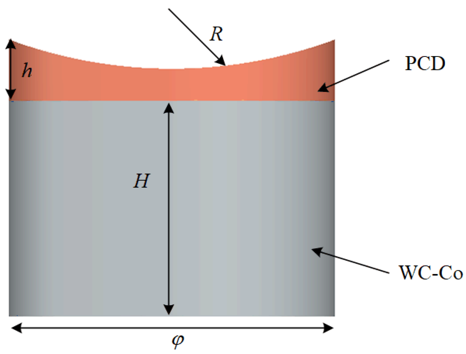
31]. In light of this phenomenon, the cutting surface of the PDC cutter has been initially conceptualized with a curved architecture, as depicted in
Figure 2. The PDC cutter comprises a polycrystalline diamond (PCD) layer paired with a Tungsten Carbide–Cobalt (WC-Co) matrix. The PCD layer possesses a thickness of 3 mm, while the WC-Co layer is 10.6 mm in height. Additionally, the arc radius (R) of the PCD layer is established at 11.5 mm (23/2 mm) and the cutter diameter (φ) measures 16 mm.
The curved structure of the cutting surface of the cutter can induce tensile stress in the rock, enhancing rock-breaking efficiency. However, this mechanism of rock fragmentation occurs after the cutter is pressed into the rock. To further improve rock-breaking efficiency, the initial process of cutter penetration into the rock needs to be considered. Therefore, a sharper structure needs to be designed to facilitate the cutter’s penetration into the rock. The process by which most animals use their teeth to break down food is shown in
Figure 3, where the sharp tooth tip pierces the food, subsequently disrupting the fibers within the food, ultimately causing it to fracture. In this process, the sharp end of teeth reduces the contact area with food, thereby minimizing resistance and facilitating easy penetration [
32]. The teeth of sharks are characterized by a serrated structure, with these serrations inclined backward, making it difficult for sharks to release their prey once bitten. To enhance the sharpness of the cutter, the design takes inspiration from the structure of shark teeth, as depicted in
Figure 4. In the design process, the structural characteristics of a wavy-shaped cutter are combined, coupling the serrated structure onto the curved cutting surface, as shown in
Figure 5. The distance between the tops of adjacent serrated edges is set at 4 mm, and to ensure the strength of the PCD surface, the depth of the serrations is designed to be 0.5 mm [
24].
The distribution of saw structures can be approximated by the following mathematical model:
where
L is the distance from the center of the ground to the perimeter of the sawtooth;
r is the distance between two adjacent sawtooth units; and
H + h is the distance from the apex of the sawtooth to the ground.
The forces on the cutter are constantly changing during the breaking process, which requires high impact resistance, toughness, strength, and wear resistance [
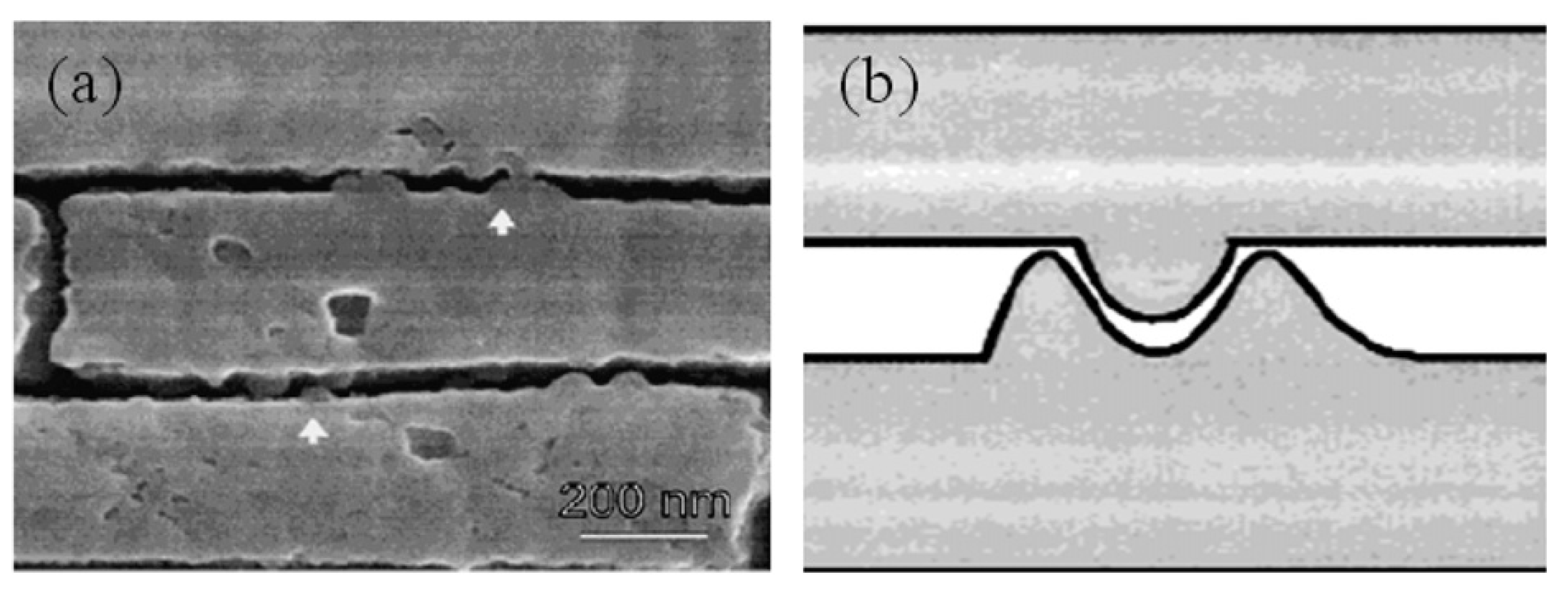
33]. However, the significant material difference between the upper and lower layers of the PDC cutter leads to the occurrence of detachment at the interface during the rock-breaking process. To prevent this phenomenon, it is considered to draw inspiration from the microstructure of materials, as shown in
Figure 6. It can be observed that the edges of the two crystals form a “convex–concave interlocking” structure, which generates elastic friction during crystal sliding. Under loading conditions, this structure induces anisotropy, absorbs more energy, and generates toughening mechanisms [
34]. Based on the toughening mechanism of the microstructure of biological materials, the interface structure of the cutter is considered to be designed as shown in
Figure 7a. In this design, the width (
a1) of the columnar structures, except for the edge region, is set at 1 mm, while the height (b) of the columnar structures is set at 1 mm. The final biomimetic PDC cutter structure is depicted in
Figure 7b, where the columnar structures in the edge region have a width (
a2) of 0.5 mm.
4. Results and Discussion
4.1. Comparison of Rock-Breaking Characteristics
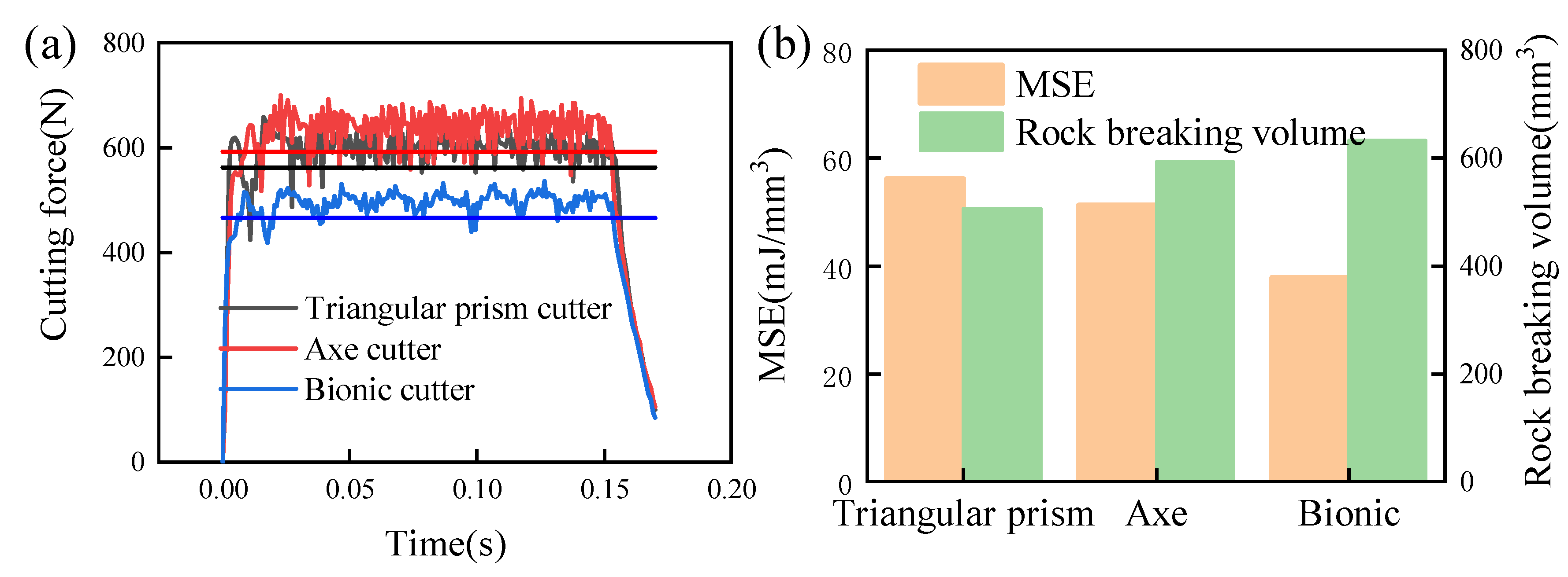
Figure 15 shows the cutting forces and MSE of the triangular prism cutter, axe cutter, and bionic cutter for a back-rake angle of 15°, a depth of cut of 1.5 mm, and a cutting speed of 0.3 m/s.
The data presented in
Figure 15a suggest that, under identical boundary conditions, the variance in cutting force experienced by the bionic PDC cutter during rock fragmentation is notably less than that of the triangular prism and axe cutters. This indicates that the bionic design may effectively diminish frictional resistance encountered during rock penetration, thereby facilitating smoother cutter engagement. Through the computation of the mean cutting force throughout the rock-breaking sequence, it is discerned that the average cutting force exerted by the bionic cutter is approximately 16.9% and 20.9% lower in comparison to the triangular prism and axe cutters, respectively. This reduction in cutting force is instrumental in enhancing the wear resistance of the cutter, averting potential failures, prolonging the operational lifespan of the cutter, and consequently diminishing drilling expenses. Furthermore, when examining the cutting force trajectories of the three PDC cutters throughout the rock-breaking process, it is observed that the bionic cutter displays a consistent pattern of force variation (with peaks aligning with initial cutter-rock contact and troughs corresponding to rock removal), in contrast to the more erratic fluctuations exhibited by the other cutters. To quantitatively evaluate the dispersion of cutting force fluctuations, the standard deviations for the cutting forces of the prism, axe, and bionic cutters were calculated as 115, 128, and 86, respectively. This analysis substantiates that the bionic cutter possesses superior cutting stability during rock fragmentation, while the axe cutter exhibits the least stability in this regard.
The data in
Figure 15b demonstrates that, under the same boundary conditions, the bionic PDC cutter achieves the maximum volume of fractured rock and exhibits the smallest MSE. Compared to the triangular prism and axe cutters, the bionic cutter experiences a reduction in MSE of approximately 32.5% and 35.37%, respectively. This demonstrates the effectiveness of bionic structural design in enhancing the efficiency of the cutter during rock breaking. Moreover, by considering both
Figure 15a,b together, it can be observed that the axe cutter achieves higher rock-breaking efficiency compared to the triangular prism cutter, but with weaker stability. This is consistent with our previous research findings [
16].
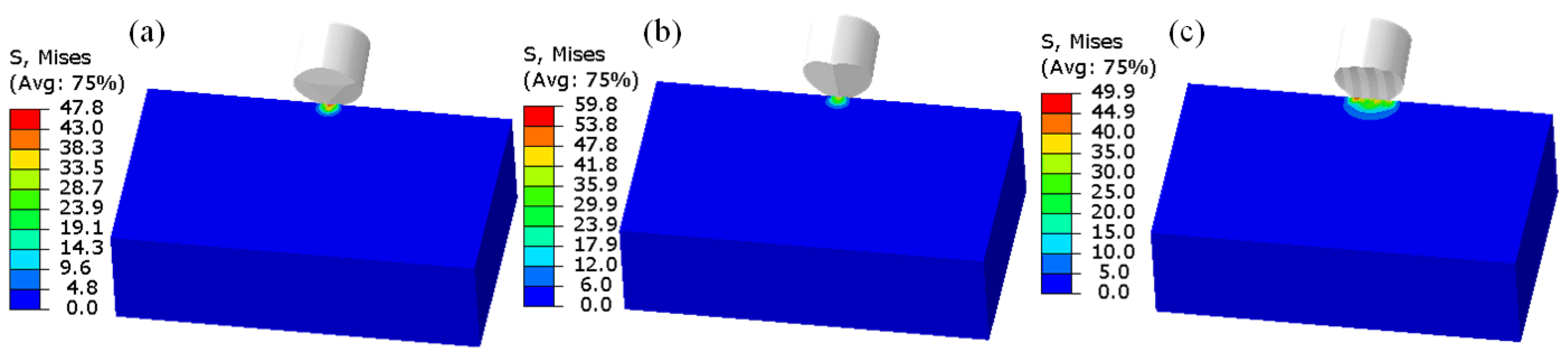
The rock-breaking efficiency as well as the stability of the bionic cutter is significantly improved compared to both the triangular prism cutter and the axe cutter, which is attributed to its unique structural design that changes the rock-breaking method of the cutter. To understand the rock-breaking characteristics of the bionic PDC cutter for subsequent design optimization, the stress contours of the three cutters at the initial moment of the rock-breaking process were recorded using ABAQUS software, as shown in
Figure 16, in MPa.
From the analysis of
Figure 16, it is evident that both the triangular prism and axe cutters exhibit analogous behaviors upon initial contact with the rock. Each employs their ridge-like structures to intensify the load at the contact point, thereby facilitating penetration into the rock for effective rock breaking. Conversely, the bionic cutter, featuring three ridge-like structures, induces multiple points of stress concentration upon contacting the rock. This multiplicity in stress concentrations not only pre-damages the rock by releasing internal stresses but also enhances the ease of subsequent rock fragmentation. Hence, the bionic PDC cutter demonstrates superior initial rock penetration efficiency, contributing to its heightened effectiveness.
Figure 17 displays the cross-sectional stress contours, quantified in megapascals (MPa), for the three different cutters during the rock-breaking process. It is discernible that, although the overall rock-breaking mechanisms of the three cutters are broadly similar—characterized by the generation of high stress upon initial rock contact, followed by the interconnection of high-stress regions culminating in rock removal—the bionic cutter uniquely exhibits a more pronounced stress concentration at the contact point, especially notable at the rock’s curved tip. This distinct feature of the bionic cutter underscores its enhanced efficiency in stress application, compared to the triangular prism and axe cutters, at the critical moment of initial contact with the rock. Therefore, during the rock-breaking process, the bionic cutter is more likely to reach the rock’s fracture limit, resulting in the lowest cutting force and the most efficient utilization of force. This is because, during the rock fracturing process, the damage to the rock depends on the stress concentration area where the cutter acts on the rock. In other words, when a stress concentration area is formed in the rock, the higher the stress value in that area, the more likely it is to reach its own stress yield limit and undergo damage. Therefore, under the same conditions, the use of bionic cutters is more likely to cause damage to the rock and remove rock chips, resulting in lower rock fracturing resistance, lower energy consumption, and higher efficiency. This point is also supported by
Figure 17. Additionally, the axe cutter generates larger volumes of rock debris during the rock-breaking process, while the other two cutters do not exhibit this phenomenon. This indicates that the axe cutter breaks the rock into larger fragments, consuming more energy and resulting in lower rock-breaking efficiency.
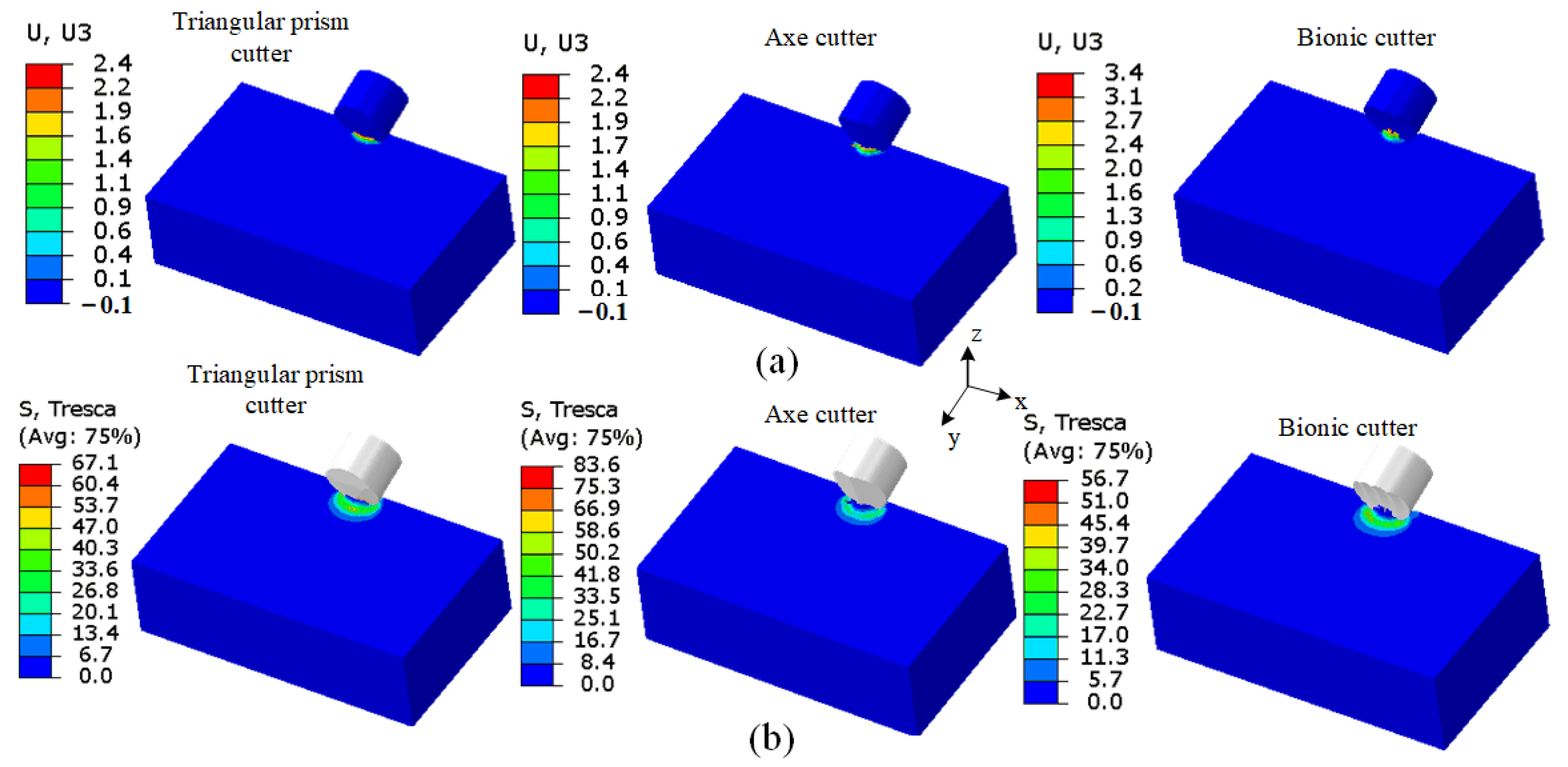
Figure 18 depicts the rock displacement contours (measured in mm) and shear stress contours (measured in MPa) of the three different cutters at the same instant during the rock-breaking process. From
Figure 16a, it can be observed that during the rock-breaking process, the bionic cutter induces larger displacement in the
Z-direction of the rock. This implies that, compared to the triangular prism and axe cutters, the bionic cutter not only exerts crushing and shearing effects on the rock but also has a “shoveling” effect, similar to the process of a mole excavating soil. At this stage, the rock is more easily fractured under tensile stress. This “shoveling” effect is the fundamental reason for the high efficiency of the bionic cutter in the rock-breaking process. Furthermore, this bionic design demonstrates the rock-breaking advantages of mole claws, transforming the rock-breaking mechanism of the PDC cutter from compression to tension, thereby enhancing efficiency. From
Figure 16b, it is evident that the bionic cutter generates the lowest shear stress on the rock, indicating its highest rock-breaking efficiency. This indirectly demonstrates that the coordination of the “shoveling” and crushing actions of the bionic cutter is the key to enhancing rock-breaking efficiency, compared to the other two cutters.
Figure 19 represents the contact stress contours (measured in MPa) during the rock-breaking process for the three different cutters. From the contours, it can be observed that due to the ridge-like structures present in all three cutters, the contact stress is generally symmetric along the ridge lines. Interestingly, the maximum contact stresses for the axe and bionic cutters are concentrated near the ridge structures, while for the triangular prism cutter, the maximum contact stress is located far away from the ridge structure. This can be explained by the fact that the axe cutter exhibits stronger aggressiveness. Compared to the triangular prism cutter, it relies on the ridge structure to exert a stronger crushing effect on the rock. Hence, the axe cutter has higher rock-breaking efficiency, and the mean cutting force of the triangular prism cutter is smaller than that of the axe cutter. The unique curved and three-ridge structure of the bionic cutter allows it to concentrate the load on the rock during operation and facilitates the fracture of the rock under tensile stress. Therefore, it experiences the lowest contact pressure during the rock-breaking process.
4.2. Effect of Back Rake Angle on Cutter Rock Breaking
The back rake angle of the cutter determines its angular position on the cutter blade of the drill bit, and a reasonable choice can effectively improve the rock-breaking efficiency of the drill bit [
41]. Therefore, simulations were conducted for the three different cutters at various back rake angles (5°, 10°, 15°, 20°, 25°) under a fixed cutting depth of 1.5 mm and cutting speed of 0.3 m/s.
Figure 20 shows the relationship between the back rake angle and the average cutting force of three different cutters (
Figure 20a corresponds to the triangular prism cutter,
Figure 20b corresponds to the axe cutter, and
Figure 20c corresponds to the bionic cutter) during the rock fracturing process, where the range of rake angle variation is from 5° to 25°. From
Figure 20a–c, it can be observed that, as the back rake angle increases, the cutting force for the triangular prism cutter significantly increases. In contrast, although the cutting forces for the axe and bionic cutters also increase, the trend is not as pronounced as for the triangular prism cutter. This implies that the triangular prism cutter may require a specific back rake angle to achieve high efficiency in the rock-breaking process, while the cutting forces for the axe and bionic cutters are less sensitive to changes in the back rake angle, allowing for a wider range of back rake angle selection in the rock breaking process. It is worth noting that, under the same conditions, with increasing back rake angle, the cutting force for the bionic cutter consistently remains the smallest among the three cutters (except for the case of a 5° back rake angle, where the cutting force for the triangular prism cutter is slightly smaller than that for the bionic cutter). This sufficiently demonstrates that the bionic structural design reduces the resistance of the PDC cutter during the rock-breaking process, thereby improving its wear resistance and lifespan. Additionally, from
Figure 20c, it can be observed that the rate of increase in cutting force for the bionic cutter becomes greater when the back rake angle exceeds 15°, indicating that 15° may be its critical back rake angle.
Through calculations, the average cutting force growth rates of triangular prism cutters with increasing back rake angles (each angle compared to the previous one) are 21.2%, 13.4%, 19.7%, and 15.9%, respectively. The average growth rates of cutting forces for axe cutters are 3.6%, 7.4%, 3.9%, and 1.2%, while for bionic cutters, they are 5.0%, 2.7%, 6.5%, and 7.7%. From the aforementioned data, it can be observed that, compared to axe and bionic cutters, triangular prism cutters exhibit a significant variation in cutting force when the rake angle increases. When installed on a drill bit, triangular prism cutters require a specific angle to maintain their efficiency, implying that their use is subject to limitations. In contrast, axe and bionic cutters maintain relatively low growth rates of cutting forces as the back rake angle increases. This suggests that, during the drilling process, the applicability of bionic and axe cutters is broader, especially for bionic cutters, as they consistently maintain lower cutting force values.
These results indicate the critical importance of choosing the appropriate cutter in the drilling process. The pronounced variation in cutting force for triangular prism cutters with increasing back rake angle may render them less suitable in certain situations. On the other hand, axe and bionic cutters demonstrate more stable performance, particularly with their relatively low growth rates of cutting forces as the back rake angle increases, making them more suitable for widespread applications.
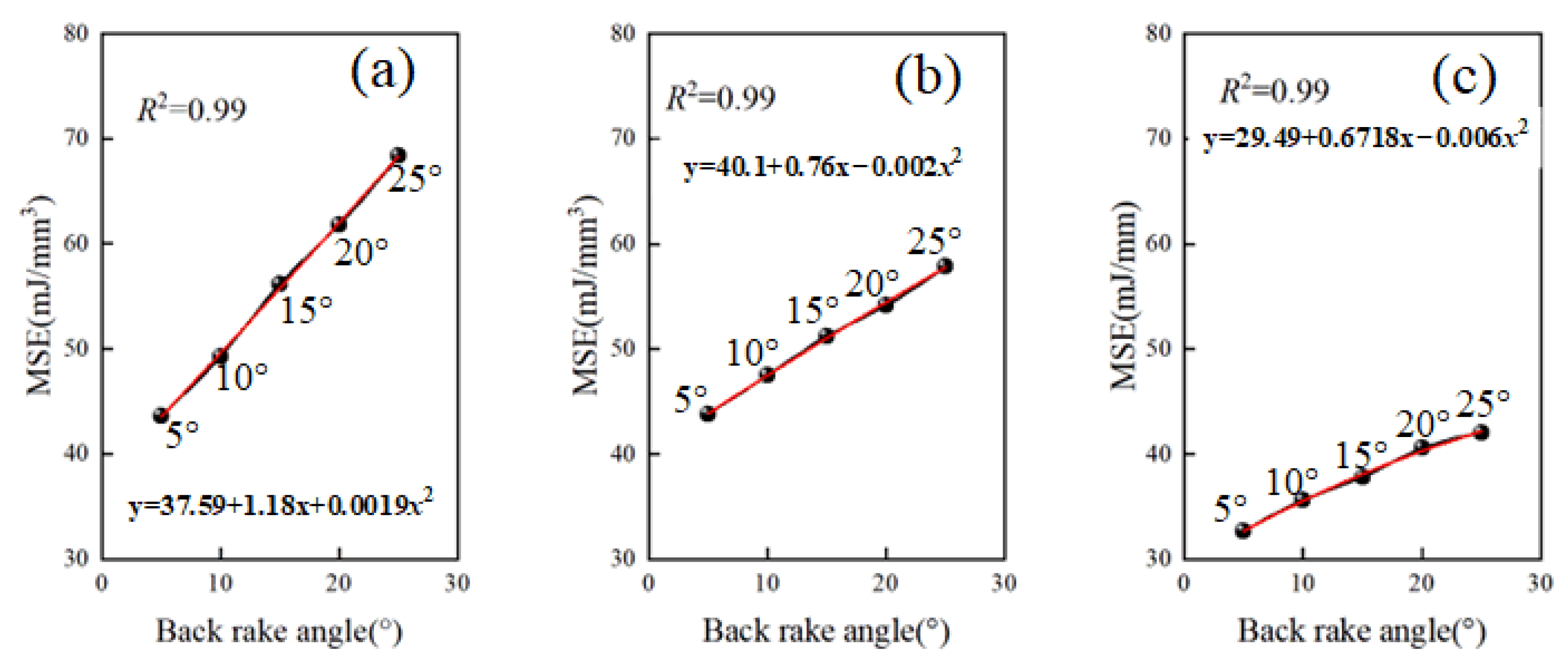
Figure 21 illustrates the relationship between the MSE and the back rake angle (5°, 10°, 15°, 20°, and 25°) for three types of cutters (
Figure 21a corresponds to the triangular prism cutter,
Figure 21b corresponds to the axe cutter, and
Figure 21c corresponds to the bionic cutter) during the rock fracturing process. Based on the data from
Figure 21a–c, it can be observed that the rock-breaking MSE for the triangular prism, axe, and bionic cutters continuously increases with increasing back rake angle. This trend observed for the triangular prism and axe cutters aligns with the findings reported in previous studies [
14,
42]. Through calculations, it has been determined that, at rake angles of 5°, 10°, 15°, 20°, and 25°, biomimetic cutters exhibit a reduction in MSE compared to triangular prism and axe cutters. The reductions are as follows: 26% and 26.9%, 25.3% and 22.5%, 31.2% and 24.6%, 31.5% and 21.8%, 37.3% and 26.2%, respectively. This indicates that bionic PDC cutters demonstrate stronger applicability in the rock-breaking process compared to triangular prism and axe cutters, showcasing their practical value for on-site use.
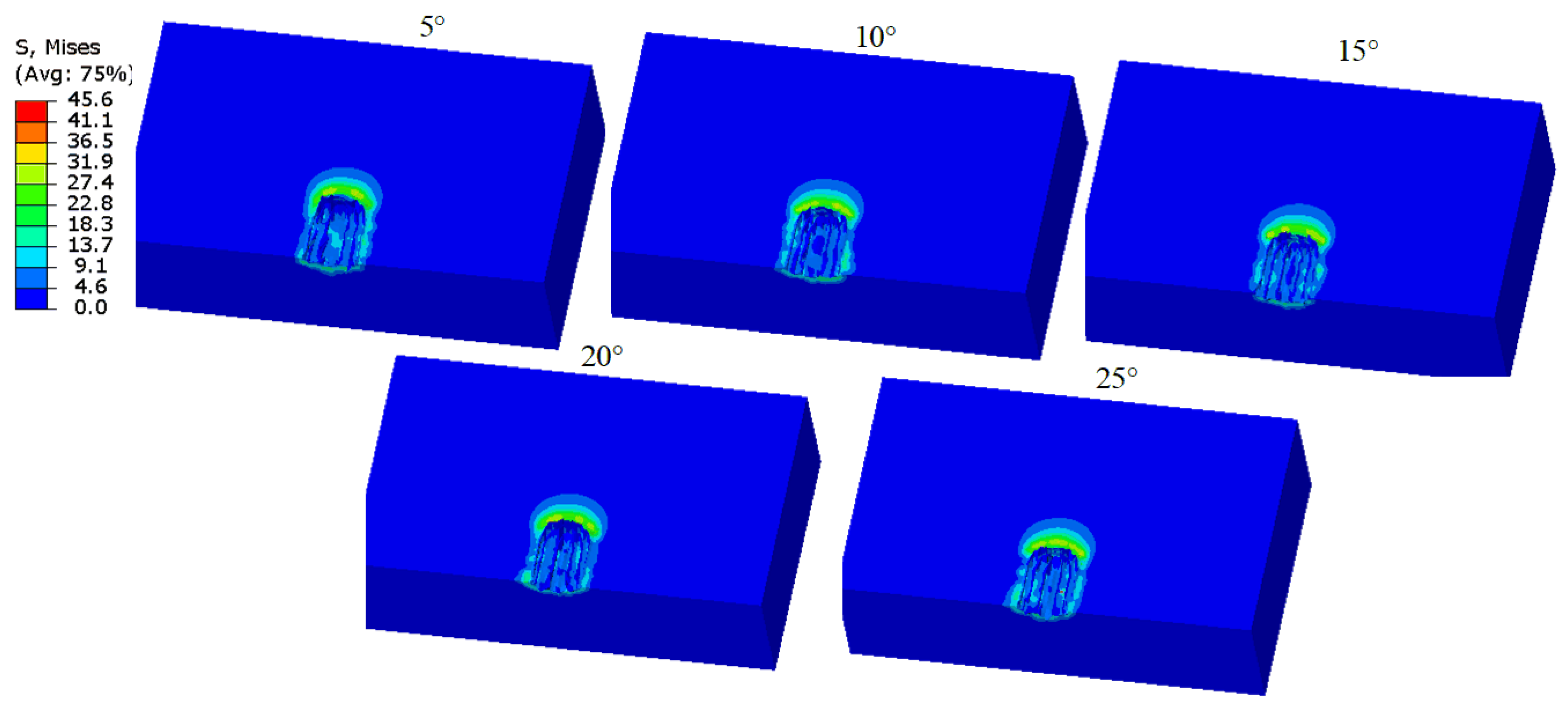
Figure 22 illustrates the contact stress distribution for the bionic PDC cutter under varied back rake angles, while maintaining all other conditions constant. The figure reveals a notable trend: as the back rake angle increases, the contact stress area on the cutter diminishes and shifts downward. This trend suggests that an increase in the back rake angle of the bionic cutter results in a reduced contact area with the rock, thereby intensifying load concentration. Consequently, the stress becomes more focused on the central ridge structure of the cutter’s surface, augmenting the cutting force, as evidenced in
Figure 20. Thus, a higher back rake angle tends to decrease the rock-breaking efficiency of the bionic cutter. Therefore, selecting an optimal rake angle for the bionic cutter, contingent upon the specific geological characteristics, is crucial to maximize its effectiveness in field applications.
The design of the bionic PDC cutter draws inspiration from the sharp structure of shark teeth, which increases the additional stress on the cutter when it bites into the rock. However, when teeth penetrate food at different angles, different mechanisms of damage occur. Therefore, it is necessary to discuss the rock-breaking process of the bionic cutter at different back rake angles.
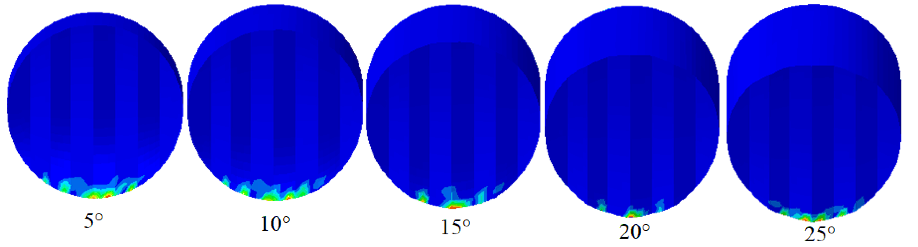
Figure 23 shows the stress contours on the rock generated by bionic cutters with different back rake angles under the same remaining conditions.
From
Figure 23, it can be observed that the stress state of the rock changes with the variation of the back rake angle of the bionic cutter. The position of the yellow region, which represents the pre-damaged area of the rock after being subjected to the cutter, can be visually observed from the figure. As the back rake angle increases, the yellow region of stress on the rock gradually converges from both sides towards the center. When the back rake angle is 25°, the phenomenon of concentration of stress in the yellow region is most pronounced. It can also be noted that, as the back rake angle of the cutter increases, the area of the yellow region of stress on the rock increases. This indicates that the aggressiveness of the cutter is gradually increasing. However, this does not necessarily mean that higher aggressiveness leads to higher efficiency. This is because forces act in reciprocity. In the case of bionic cutters causing pre-damage to a larger area of rock, they may encounter greater resistance, resulting in decreased efficiency, which is consistent with the conclusions drawn from
Figure 20 and
Figure 21.
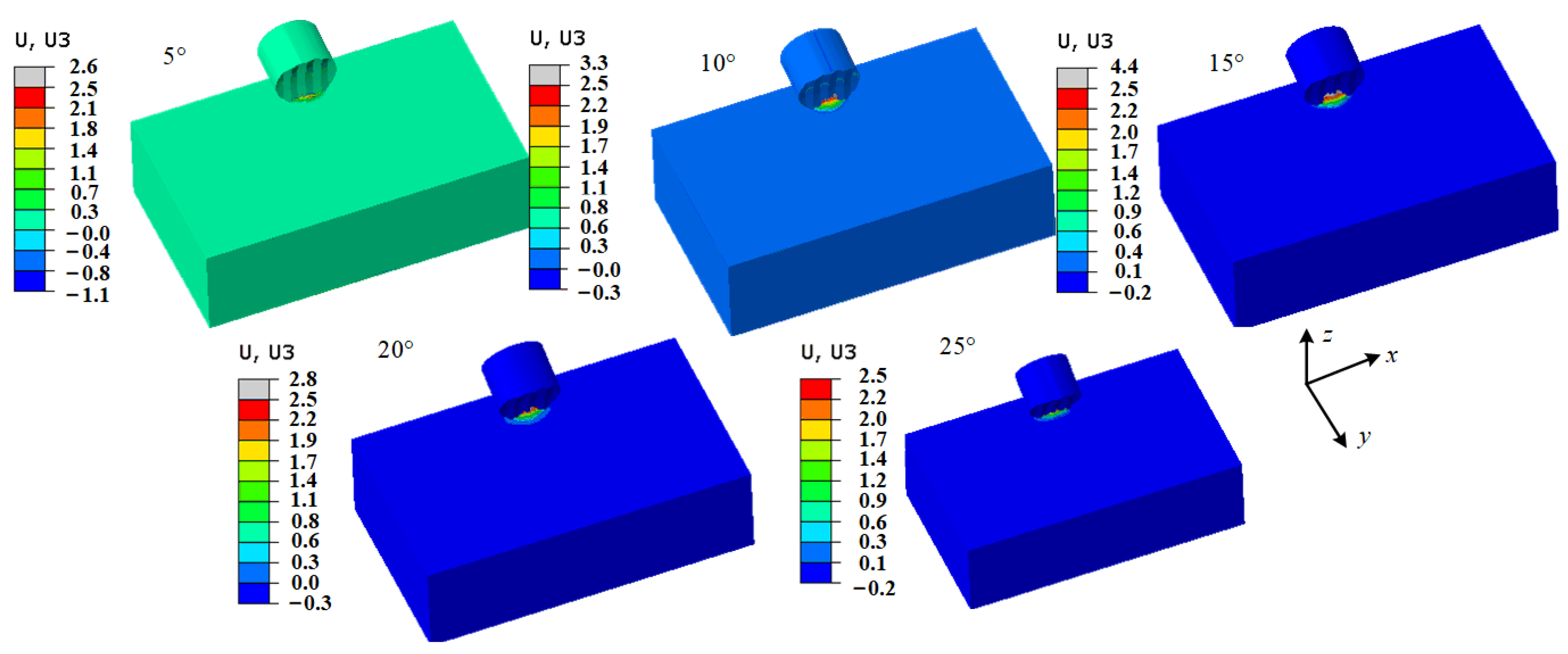
While the bionic cutter incorporates characteristics of both shark teeth and mole claws, it is also necessary to consider the effect of the cutter “shoveling” the rock at different back rake angles. This effect is represented by the displacement of the rock in the
Z-direction, as shown in
Figure 24.
From
Figure 24, it can be observed that as the back-tilt angle of the bionic cutter increases, the displacement of the rock in the
Z-direction initially increases and then decreases. The maximum displacement occurs when the back rake angle is 15°. It can be concluded that within the simulated range, the cutter exhibits the best “shoveling” effect on the rock at a back rake angle of 15°. However, according to the results from
Figure 20 and
Figure 21, the efficiency of the bionic cutter is not the highest at a back rake angle of 15°. This may be related to the contact area between the cutter and the rock, as shown in
Figure 22. Due to the coupling of the arc and sawtooth structures, the contact area between the cutter and the rock gradually decreases at different back rake angles. This implies that the performance of the bionic cutter is limited by the contact area between the cutter and the rock. In other words, under the same remaining conditions, the performance of the cutter is determined by the back rake angle. According to the literature [
43], it is impractical to use a back rake angle that is too small or too large for the cutter in the field. Generally, a range of 10° to 30° is recommended. Therefore, based on the simulation results, we recommend a back rake angle of 10° for the bionic cutter and 15° for use in harder strata.
4.3. Effect of Depth of Cut on Cutter Rock Breaking
Figure 25 reflects the variation of cutting forces for the three cutters at a back rake angle of 15°, a cutting speed of 0.3 m/s, and different depths of cut (1 mm, 1.5 mm, 2 mm, 2.5 mm, and 3 mm).
The data in
Figure 25 indicate that the cutting forces for all three cutters gradually increase with the increase in cutting depth. The primary reason for this phenomenon is that as the cutting depth increases, the contact area between the cutter and the rock increases, resulting in increased frictional forces and a nonlinear growth in cutting forces. Compared to the relationship between back rake angle and cutting forces, the relationship between cutting depth and cutting forces is more complex. Despite the overall increase in cutting forces, the bionic cutter continues to experience the lowest cutting forces, demonstrating its strong applicability in rock-breaking depths and further confirming the effectiveness of the bionic structural design in enhancing the performance of the cutter in rock-breaking. Additionally, from
Figure 25c, it can be observed that the rate of increase in cutting forces for the bionic cutter becomes significantly higher when the cutting depth exceeds 2 mm. This suggests that in the rock-breaking process, it is advisable to avoid exceeding a cutting depth of 2 mm for the bionic cutter on the drill bit.
Figure 26 shows the variation of MSE for the three cutters at different cutting depths (with all other conditions held constant). The data in the figure demonstrate that, as the cutting depth increases, the MSE for all three cutters also increases. This implies that an increase in cutting depth results in a decrease in the efficiency of the rock-breaking process. The reason for this is that as the cutting depth increases, the rock undergoes a transition from plastic deformation to brittle fracture, leading to a reduction in the efficiency of the rock-breaking process [
6]. Although the volume of fragmented rock increases, the removal of rock by the cutter requires more energy due to increased frictional forces, resulting in a decrease in rock-breaking efficiency. It is worth noting that, compared to the axe and triangular prism cutters, the bionic PDC cutter consistently maintains lower average cutting forces. This fully demonstrates the advantages of the bionic cutter in the rock-breaking process.
4.4. Effect of Arc Radius on Rock Breaking by Bionic Cutters
The analysis of the rock-breaking characteristics of the cutter indicates that the radius of the arc on the cutting surface of the bionic cutter plays a role in inducing tensile stress in the rock, thereby effectively enhancing the rock-breaking efficiency of the cutter. Therefore, it is necessary to further investigate the parameters related to the radius of the arc. Rock breaking simulations were conducted for bionic cutters with different arc radii (19 mm, 21 mm, 23 mm, 25 mm, 27 mm) under the conditions of a cutting speed of 0.3 m/s, a cutting depth of 1.5 mm, and a back rake angle of 15°.
Figure 27 illustrates the cutting forces and mechanical specific energy for bionic cutters with different arc radii under the same conditions. The data in
Figure 27a indicate that the cutting forces of the bionic cutter exhibit a trend of initially increasing, then decreasing, and then increasing again with increasing arc radius. The variation of mechanical specific energy in
Figure 27b also follows a similar pattern. This suggests that the influence of the arc radius on the bionic cutter does not exhibit a definitive pattern. However, within the current range of simulations, the optimal arc radius for the bionic cutter is likely to be in the range of 21 mm to 23 mm. This is because, based on the images, within the range of our simulation, both the MSE and cutting force of the bionic cutter are in a decreasing state when the arc radius is between 21 mm and 23 mm. However, beyond this range, both the mechanical efficiency and cutting force start to increase again. This indicates the existence of a minimum value within the range of arc radius from 21 mm to 23 mm. However, our purpose is to conduct preliminary research on the biomimetic PDC tooth and we have not delved into more detailed numerical considerations. This issue will be further investigated in future studies in order to obtain the optimal arc parameters for the bionic PDC cutter.
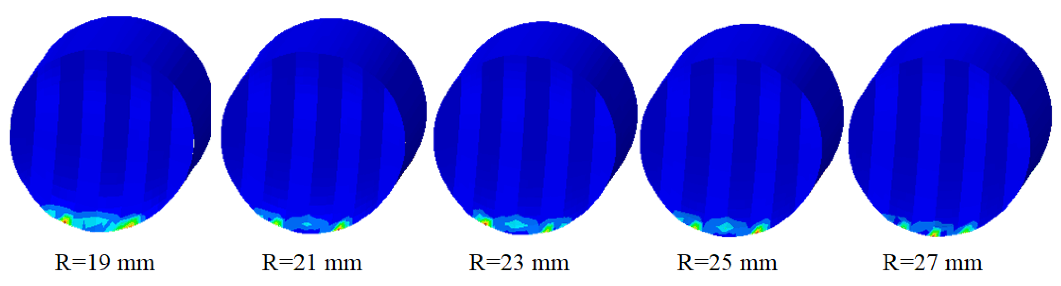
Figure 28 illustrates the distribution of contact stress during the rock-breaking process for cutters with varying arc radii. It is evident from
Figure 28 that when the arc radius (R) is 19 mm and 23 mm, the stress distribution area on the cutter surface is the largest. By correlating this information with
Figure 27, it becomes apparent that in these two scenarios, both the average cutting forces and the MSE of the cutter are reduced. Consequently, it can be inferred that changes in the arc radius impact the contact position between the bionic cutter and the rock. This, in turn, leads to stress concentration on the cutter surface in specific cases, such as arc radii of 21 mm, 25 mm, and 27 mm. This stress concentration results in localized excessive forces, thereby influencing the stability and efficiency of the rock-breaking process. Consequently, it is imperative to ascertain the optimal arc radius for different formations.
4.5. Consider the Hydrostatic Pressure of the Cutter Rock Breaking
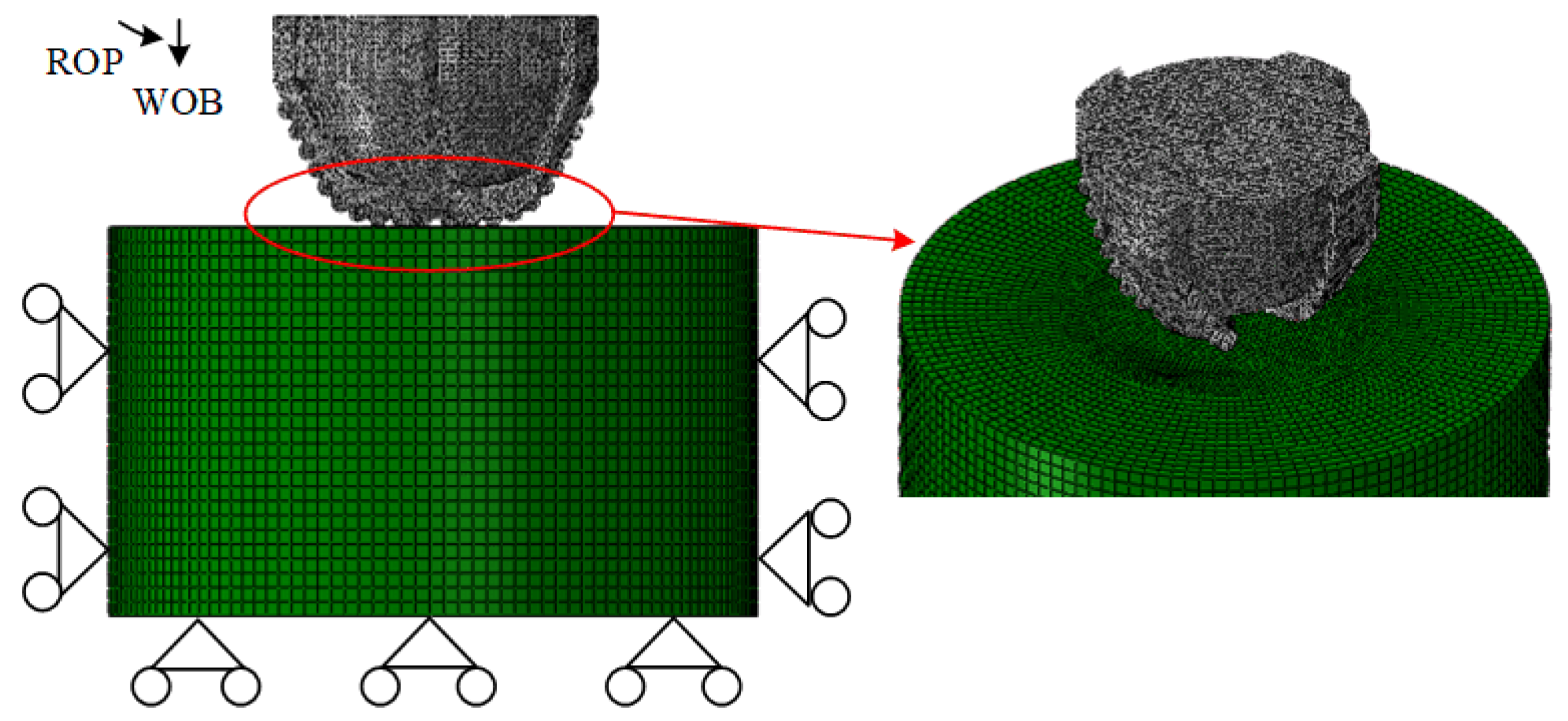
In deep geological formations, the drilling ability of the rock deteriorates due to the influence of hydrostatic pressure, leading to a decrease in the rock-breaking efficiency of the cutter. Therefore, to fully validate the effectiveness of the bionic cutter, simulations of rock-breaking using the bionic PDC cutter were conducted at a back rake angle of 15°, a cutting depth of 1.5 mm, and a cutting speed of 0.3 m/s, under different hydrostatic pressures (5 MPa, 10 MPa, 15 MPa, and 20 MPa). A comparison was made with the axe and triangular prism cutters under the same conditions. The applied hydrostatic pressure is shown in
Figure 29, where all surfaces of the rock, except the bottom surface, were subjected to vertically applied hydrostatic pressure perpendicular to the rock surface.
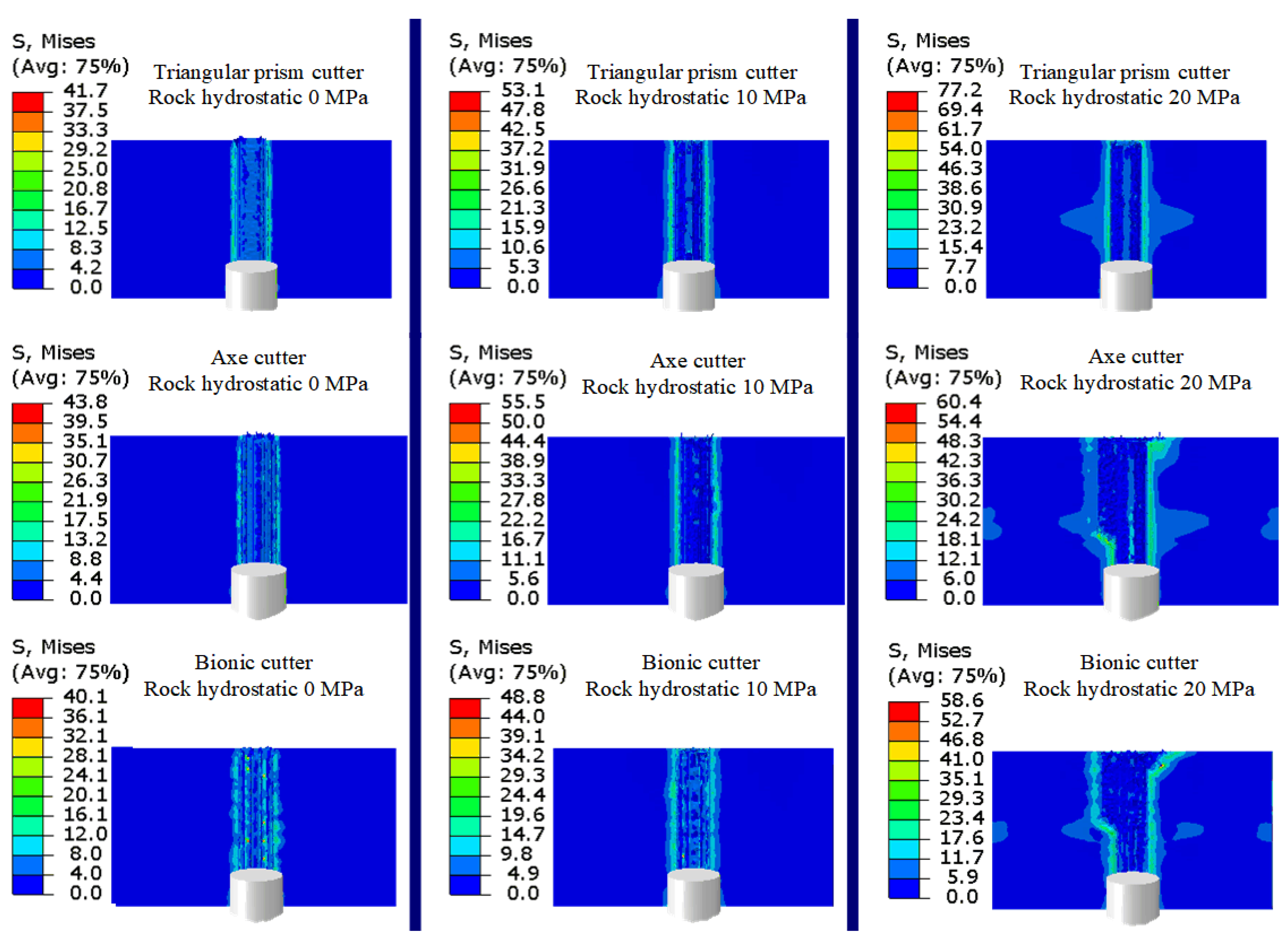
Figure 30 shows the stress distribution maps of rock formations after rock breaking using the three different cutters under varying confining pressures (represented by 0 MPa, 10 MPa, and 20 MPa).
It can be observed that as the hydrostatic water pressure increases, the post-rock-breaking stress in the formations also increases for all three types of cutters. However, the bionic cutter exhibits the lowest stress in the rock formations after rock breaking, even under high hydrostatic water pressure. This suggests that the bionic cutter is more effective in releasing the internal stress within the formations compared to the other two cutters.
To validate the hypothesis regarding
Figure 30, the average cutting forces (
Figure 31a) and MSE (
Figure 31b) of the three cutters were recorded under different net water pressures (5 MPa, 10 MPa, 15 MPa, and 20 MPa). Based on the data in
Figure 31a,b, it can be observed that the rock-breaking resistance and MSE of the three cutters exhibit an almost linear increase with increasing hydrostatic pressure. This indicates that the rock-breaking efficiency of all three cutters decreases as the hydrostatic pressure increases. This is attributed to the increase in hydrostatic pressure strengthening the cohesive forces within the rock, making it more difficult for the cutters to penetrate the rock, thus reducing their drill ability.
However, interestingly, within the range of simulations, it was found that the bionic cutter exhibited an MSE lower by 24.6% and 31.2%, 26.7% and 24.8%, 21.5% and 23.7%, 19.1% and 20.1%, and 13.2% and 12.7% than the triangular prism and axe cutters under different hydrostatic pressures of 5 MPa, 10 MPa, 15 MPa, and 20 MPa, respectively. These data indicate that the biomimetic cutter consistently exhibits the lowest rock-breaking resistance and has a significant advantage in terms of rock-breaking efficiency compared to the other two cutters. Combining this with the rock stress in
Figure 30, it can be concluded that the unique structure of the bionic cutter facilitates the easier release of internal stress within the rock during rock-breaking, thereby enhancing the rock-breaking efficiency. The increase in hydrostatic pressure indicates that the formations are located at greater depths. Therefore, the designed biomimetic cutter demonstrates superior performance in rock-breaking in deep geological formations compared to the axe and triangular prism cutters.
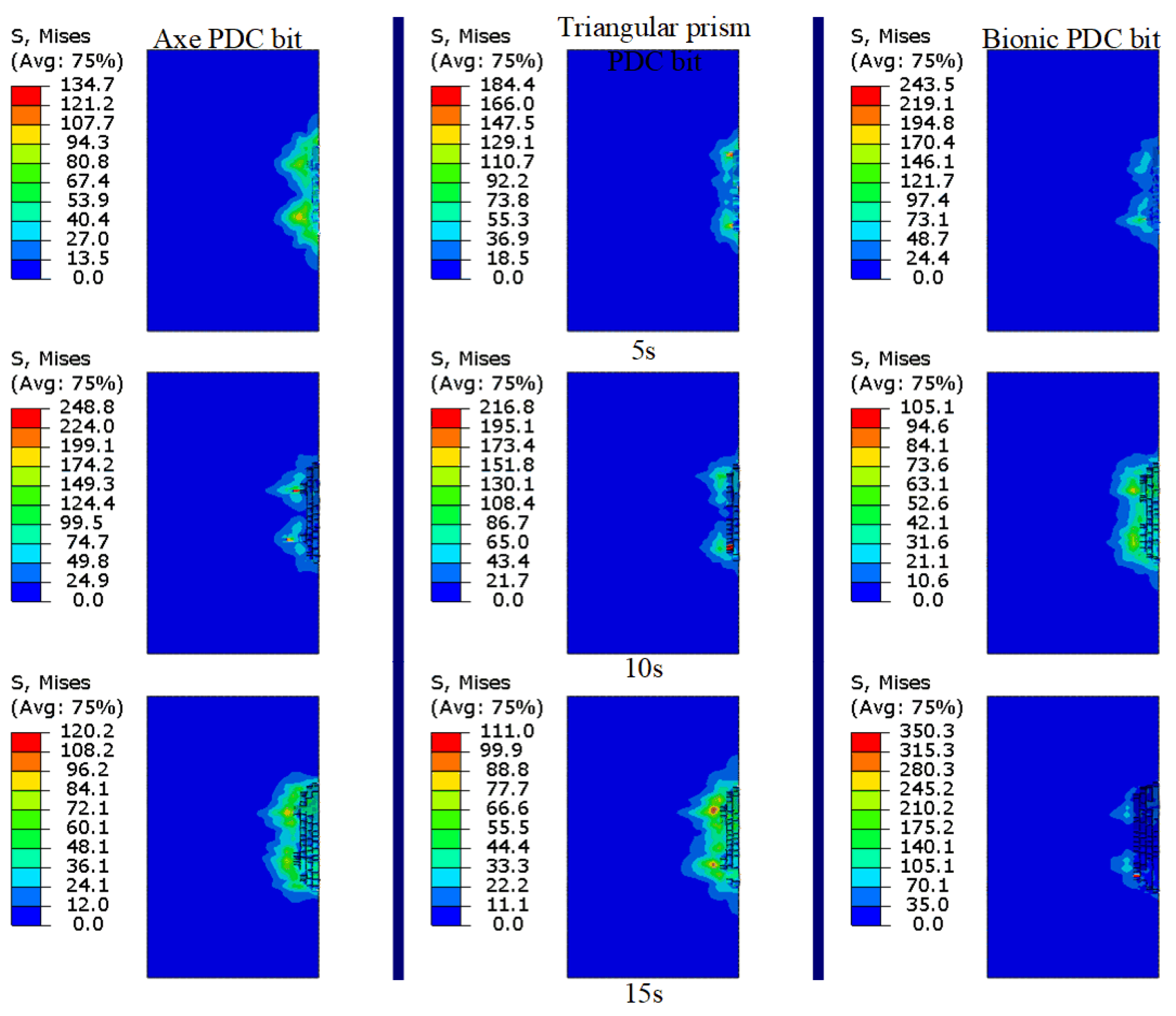
5. Numerical Simulation of Rock Breaking for Full-Size Drill Bits
Figure 32 illustrates the stress distribution at different time steps during the rock-breaking process for the three types of drill bits, with stress values given in MPa. The first row corresponds to a simulation time of 5 s, the second row corresponds to 10 s, and the third row corresponds to 15 s. From the figure, it can be observed that, at the same time step, the bionic drill bit achieves the greatest penetration depth, while the triangular prism drill bit achieves the smallest penetration depth. It can also be seen that, under the WOB, both the triangular prism and axe drill bits generate symmetric stress distributions in the rock, while the bionic drill bit generates a relatively asymmetric stress distribution, indicating a stronger penetration ability. This asymmetry may affect the efficiency of the drill bit in the rock-breaking process, thus resulting in higher rock-breaking efficiency. The reason for this is that the asymmetric stress generation indicates that the drill bit is more capable of transferring energy or stress to one side during the rock fracturing process, making the rock on that side more prone to stress concentration and fracturing, thereby enhancing rock fracturing efficiency [
44].
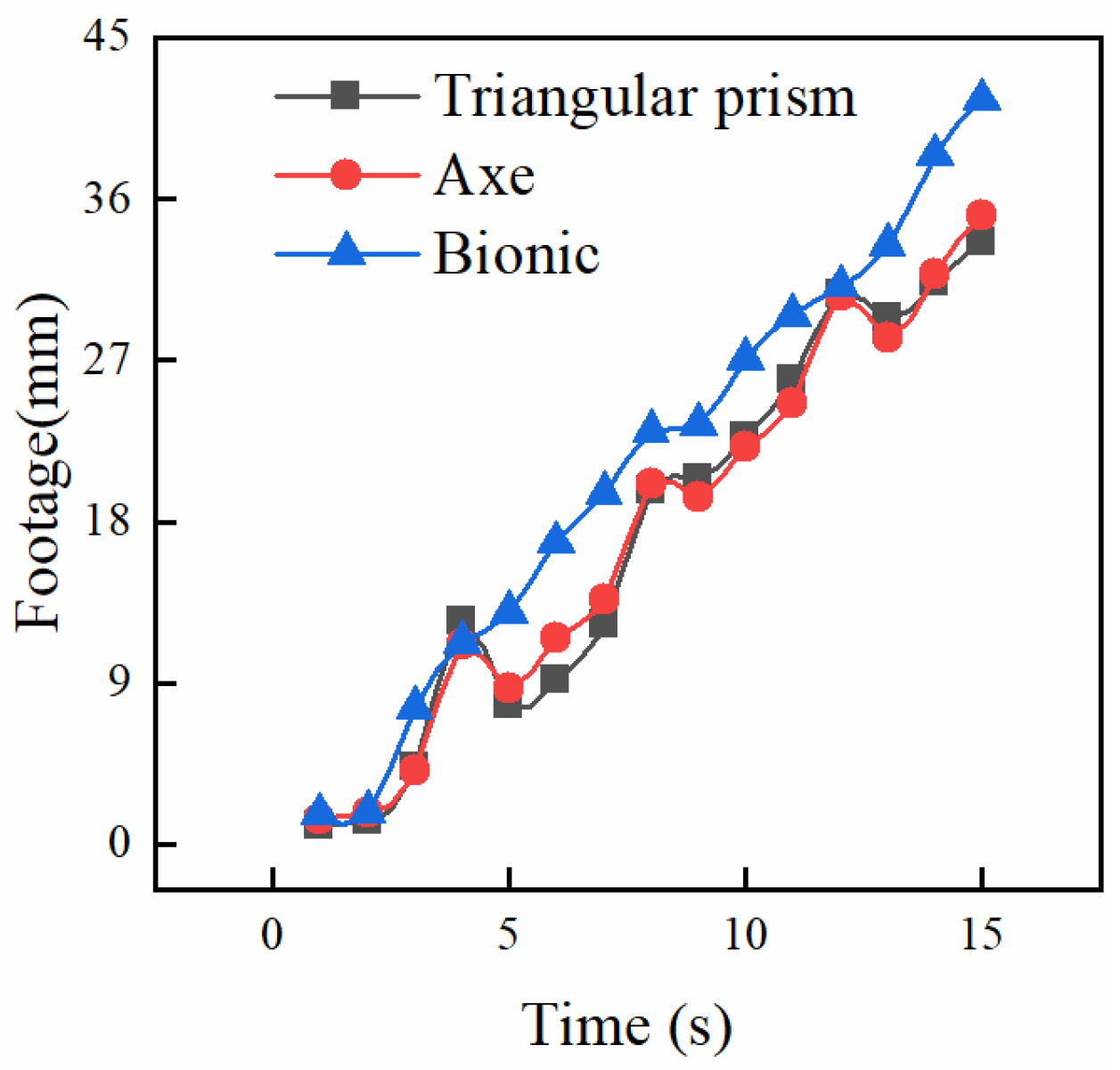
Figure 33 presents the penetration depth of the three types of drill bits over the simulated time. The data in the figure show that, at the end of the simulation, the PDC drill bits with triangular prism, axe, and bionic cutters achieved penetration depths of 33.62 mm, 35.1 mm, and 41.5 mm, respectively. The PDC drill bit with the bionic cutter exhibited an improvement of 23.4% and 18.2% in penetration depth compared to the drill bits with triangular prism and axe cutters, respectively. This indicates that the bionic cutter has great potential in enhancing the efficiency of rock breaking for drill bits and can provide significant support for field applications. Furthermore, in our previous research, the structurally symmetric triangular prism cutter exhibited higher stability and efficiency in rock breaking in complex hard formations compared to the axe cutter, which had a stronger aggressive ability [
16]. However, in this study, the efficiency of the axe cutter was found to be higher than that of the triangular prism cutter, indicating that the axe cutter with stronger aggressive ability has an advantage in breaking softer formations. From the data in
Figure 33, it can also be observed that during the drilling process, there are fluctuations in the displacement of the drill bit. This may be due to longitudinal vibrations resulting from insufficient WOB. However, the PDC drill bit with the bionic cutter exhibited the smallest fluctuations during the rock-breaking process, indicating a lower likelihood of bit bouncing and facilitating stable WOB, thus enhancing the efficiency of rock breaking.
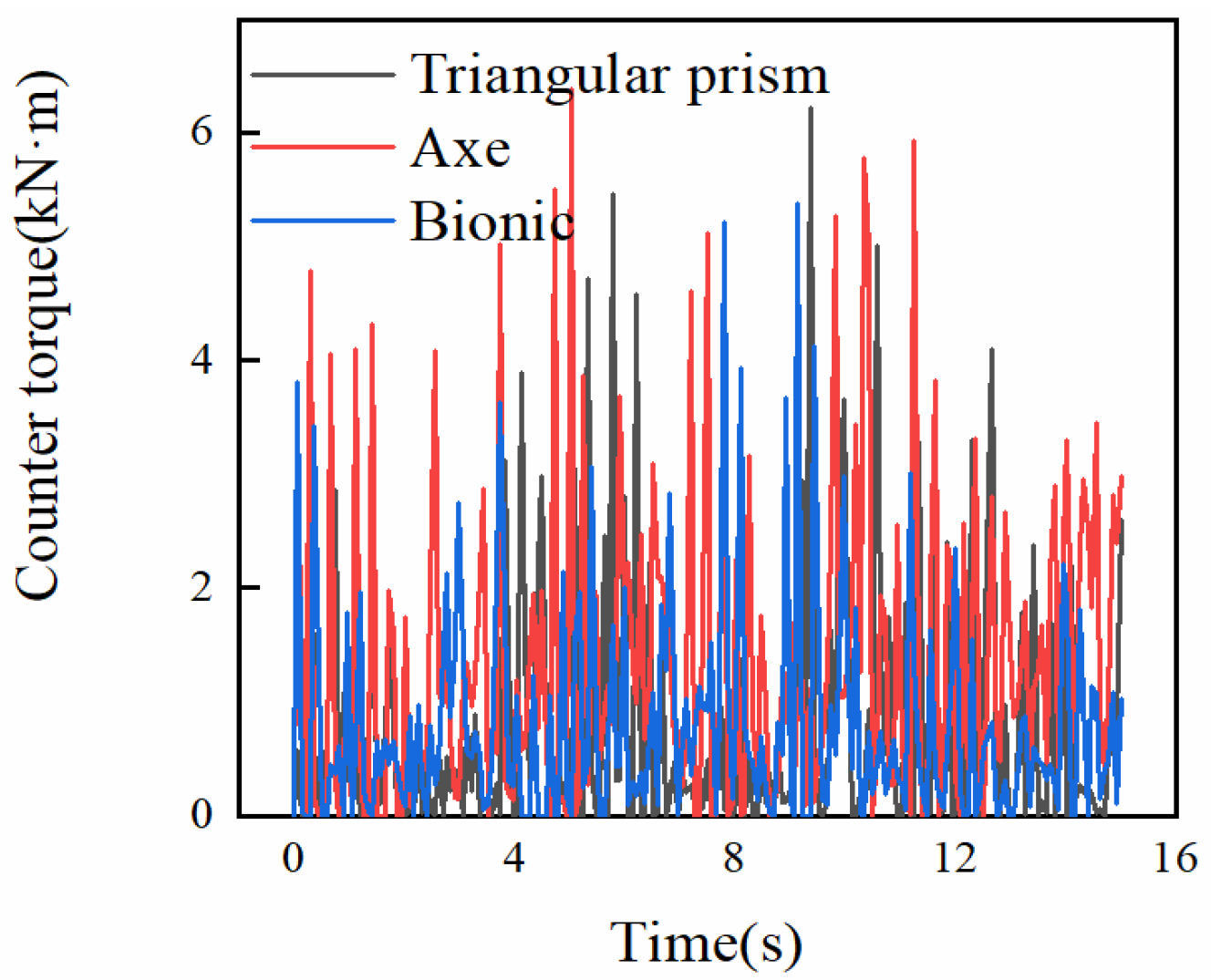
Figure 34 depicts the torsional resistance experienced by the three types of drill bits during the rock-breaking process. The data in the figure show that the torsional resistance on the drill bits fluctuates during the rock-breaking process. This is because the drill bit initially requires a significant amount of energy to penetrate the rock but, as it penetrates, the stress in the rock is released, resulting in a decrease in the torque required by the drill bit. Each type of drill bit exhibits different patterns of torsional fluctuations due to variations in their drilling efficiency.
However, in the majority of cases, drill bits equipped with the bionic cutter experience lower torsional resistance compared to the other two types of drill bits. This suggests that the utilization of the bionic cutter facilitates easier penetration into the fragmented rock. To quantitatively assess the extent of torsional resistance variation, the standard deviations of torsional resistance were computed for the drill bits with triangular prism, axe, and bionic cutters, resulting in values of 1.22, 1.42, and 1.19, respectively. These data indicate that the bionic cutter demonstrates a more stable drilling process compared to the triangular prism cutter, while the cutting process of the axe cutter is the least stable.
Furthermore, the torsional resistance also reflects the “stick-slip” phenomenon during the rock-breaking process. The maximum and minimum torsional resistance values for the triangular prism cutter are 6.2 kN·m and 2.78 × 10⁻¹² kN·m, respectively. For the axe cutter, the maximum and minimum torsional resistance values are 6.38 kN·m and 8.75 × 10⁻¹⁴ kN·m, respectively. The bionic cutter exhibits maximum and minimum torsional resistance values of 5.38 kN·m and 7.87 × 10⁻¹² kN·m, respectively. It can be observed that the bionic cutter exhibits the smallest difference between the maximum and minimum torsional resistance values, indicating a lower torque requirement during the drilling process and a lower probability of experiencing the “stick-slip” phenomenon.


