Abstract
Accurate mathematical patterning of friction has always been a significant research project in the domains of machinery and control, and has played a crucial role in the analysis, control and compensation of mechanical systems containing friction. For high-property electrohydraulic servo control systems, friction compensation is an urgent problem to be solved. The LuGre friction pattern can represent most frictional behaviors, but the LuGre friction pattern is piecewise-continuous, making it non-differentiable. Therefore, the question of how to combine the LuGre friction pattern, enhancing its tracking capacity and robust performance problem, to friction perturbation in hydraulic backstep devices is an important focus for research. In this study, the conventional LuGre friction pattern was enhanced using the continuous differentiability of a friction of rest pattern that laid the foundation of a smooth tangent function. Laying the foundation of an electrohydraulic servo pump-controlled hydraulic roll-gap thickness automatic control system (pump-controlled AGC) pattern, a self-adapting friction compensation controller laid the foundation of the enhanced LuGre pattern. The gradual tracking capacity was determined academically using conditions of parameter, uncertainty and nonlinear friction, and the position control precision of the pump-controlled AGC system was enhanced. The steady-state error of the self-adapting friction compensation control system, which laid the foundation of the enhanced LuGre pattern, attained ±0.1 μm, and the tracking capacity was better than the LuGre pattern control and the conventional PID control strategy at low input speed.
1. Introduction
In applications that require high dynamic characteristics, the response speed of the pump-controlled system is average [1], and the pump-controlled electrohydraulic servo system is subject to certain limitations [2]. Thus, a comprehensive study on a pump-controlled electrohydraulic servo system was conducted to enhance the dynamic response capacity of the system and meet the demands of realistic application. It is of vital consequence to develop a pump-controlled electrohydraulic servo system with wide adaptability, stable operation and low noise [3,4,5]. Previously, the pump-controlled AGC of a lithium battery pole strip mill was studied. As shown in Figure 1, a self-adapting robust controller with eminent capacity was laid into the foundation of the dynamic friction pattern. Nevertheless, the LuGre friction pattern is sectionally continuous, which makes it non-differentiable. Due to this, the differential of the LuGre friction term is often used when devising the backstep to address the mismatched nonlinear friction of the hydraulic system. Combining the LuGre friction pattern with a hydraulic backstep device to enhance tracking capacity and robust performance with friction perturbations remains a research focus [6,7,8].
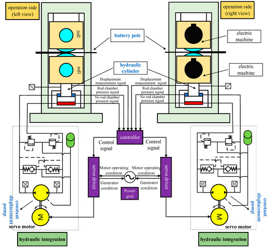
Figure 1.
Working principle of the electrohydraulic servo pump-controlled AGC.
Electrohydraulic servo systems have many pattern uncertainties [9,10,11,12] that cannot be accurately patterned, including exterior interference, leakage and friction. Their nonlinear function positions can be accurately described [13,14,15]. These uncertainties are known as uncertain nonlinearities, and self-adapting control technology can effectively address parameter uncertainties [16,17,18]. Friction is prevalent in mechanical servo systems and is a main source of damping. In particular, it has an important effect on the servo capacity of the system at low speeds. Nonlinear multi-source perturbations and other problems are present in AGC systems controlled by a lithium battery pole plate pump [19,20], imposing high demands for the control capacity of hydraulic AGC in the rolling process.
With continuous industrial development in the industry, the control precision of pump control hydraulic systems is increasing. As a result of this, control of the pump position has received increased attention. Maghareh et al. [5] and Van et al. [21] developed a physical pattern based transformation of the dynamic pattern of a nonlinear physical system, coupling a servo hydraulic actuator with a steerable standard formalization and sensor fault-tolerant control (SFTC) for position-tracking control. To enhance the double-pitch angle control capacity, Yin et al. [22] came up with an article electrohydraulic servo double-pitch system for wind turbines. By making up a specific new Lyapunov function, accurate tracking of the expected pitch angle track and compensation for the pattern indeterminacy and interference were realized. For electric hydrostatic actuator (EHA) positioning systems with faulty cylinder piston seals, Ren et al. [23,24] introduced the device and experimental evaluation for a stationary tone-up fault-tolerant control (FTC) scheme which laid the foundation for quantitative feedback theory (QFT). To limit the position tracking deviation and load pressure within their several capacity confines, Guo et al. devised a controller using the Barrier Lyapunov function (BLF) and combined the dynamic surface, parameter estimation and perturbation estimation [25] to solve the problem of a single rod EHA with hydraulic parameter uncertainty and exterior load perturbation. Zhang [26] used the vector control method to realize the decoupling control of the motor. In order to enhance the low-speed resolution of the speed loop, the low-speed detection method that laid the foundation of the speed observer was adopted for the speed loop, and the LQG control method was adopted for the position loop to achieve the target of low-speed position tracking. Bobo et al. [9] came up with a controller for a servo motor pump direct drive system, and devised an ARC controller with a reverse step for this system. Laying the foundation of nonlinear dynamics and uncertain parameters, the self-adapting robust control (ARC) algorithm was adopted to accurately track the target track. The controller adopted a three-step reverse step control strategy. Xiang et al. [27] combined a nonlinear self-adapting fuzzy backstepping controller with a self-adapting fuzzy controller for real-time tracking control of an electrohydraulic loading system. Compared to the conventional PID controller with velocity feedforward, the nonlinear self-adapting fuzzy backstepping controller (NAFBC) has more satisfactory capacity in the electrohydraulic loading system, including tracking precision and buffeting.
A new friction of rest pattern that laid the foundation for a smooth hyperbolic tangent function was referenced [28] to reflect the Stribeck effect in actual systems. Many experimental results have shown that the friction pattern can accurately describe an actual hydraulic system. The main advantages of the friction pattern are that it is flowing and differentiable. In this paper, the conventional LuGre friction pattern is enhanced by exploiting this continuously differentiable property, and its effectiveness is verified using a hydraulic pump. A self-adapting friction compensation controller laying the foundation for an enhanced LuGre pattern also came up, and the unknown parameters and unmeasured intrinsic states in the LuGre pattern were estimated. The controller is capable of academically obtaining gradual tracking capacity when parameter uncertainty and nonlinear friction are present; it is also capable of tracking robust unpatterned uncertainties, including exterior perturbations in the system [29].
This paper is organized as follows. Section 2 explains the pump-controlled cylinder system pattern, presents the problem description and provides detailed information on the equations used in the research. Section 3 describes the new continuously differentiable pattern, introduces the enhanced LuGre friction pattern and describes the system remake upion. In Section 4, a self-adapting friction compensation controller is devised, laying the foundation for the enhanced LuGre pattern; the capacity of the self-adapting controller is also introduced. Section 5 presents the verification of the simulation experiment, which is summed up in Section 6.
2. System Pattern and Emerson Characterization
The electrohydraulic control system has two categories: a valve control system and pump control system. Within the valve control system, the pipeline loss is large, system efficiency is low and a large amount of gravitational potential energy and braking energy are converted into heat energy, resulting in system heating. Compared to the valve control system, the pump control system eliminates the flow control valve, eliminates the throttling loss and vitally enhances the system efficiency. Under the condition of constant speed, the output flow is a variable pump and the reverse is a quantitative pump. The biggest difference between them is that the shaft of the variable pump is mounted eccentrically. Simply put, after the speed of the quantitative pump is selected, its flow cannot be adjusted. The exportation flow of the variable pump can automatically adjust the flow according to the pressure change of the system (the size of the exterior load), that is, the exportation flow is small when the pressure is high, and the exportation flow is large when the pressure is low; therefore, we can save the number of hydraulic components, thus simplifying the oil circuit system and reducing the oil heating. The disadvantage is that the flow pulsation is serious, the system pressure is not smooth, the pump life is short, the pump bearing is easy to break because it has eccentric installation and the pump noise is loud. Therefore, this paper chooses the quantitative pump as the research object.
The hydraulic pump is the power component of the hydraulic system. It converts the mechanical energy of the motor into a hydraulic energy conversion device, exports flow and pressure and contains high volumetric efficiency. Its function is to provide pressure oil to the hydraulic system, and from the energy conversion point of view, it will be the prime mover (such as the engine) in the exportation of mechanical energy into the pressure energy of liquid, which makes it easy to transport. The hydraulic motor belongs to the executive element, which can convert the pressure energy of the input liquid into the mechanical energy of the exportation shaft rotation, which is used to drag the load and conduct work. Working speed refers to the actual rotation speed of the pump (or motor) at work. Rated speed refers to the highest speed that can operate normally for a long time under rated pressure. If the pump exceeds the rated speed, it will cause insufficient oil absorption, vibration and loud noise, parts will suffer cavitation damage and life will be reduced. The minimum stable speed refers to the minimum speed allowed for normal operation of the motor. At this speed, the motor does not crawl.
The hydraulic system investigated in this section is illustrated in Figure 2. The inertial load is driven by a hydraulic cylinder controlled by a variable pump. In this hydraulic system, the oil supply pressure was maintained constantly by the safety valve and accumulator; the oil return pressure was relatively small because it was directly connected to the oil tank. The working principle of the electrohydraulic servo pump control system established in this study is shown in Figure 3, which is mainly composed of the servo motor, quantitative pump, oil replenisher module and execution unit. The controller exportations included the torque speed command to the servo motor, adjusting the exportation pressure flow of the quantitative pump and controlling the exportation force and displacement of the hydraulic cylinder piston. To ensure that the inertial load tracks smooth position instruction as much as possible, the dynamic equation of the inertial load is:
where and represent the load mass and hydraulic cylinder displacement of the load, severally. is the load pressure; and are, respectively, the pressure of the two chambers of the hydraulic cylinder; is the hydraulic cylinder piston acting area; , is the nonlinear friction and is the unpatterned dynamic, including exterior perturbations.
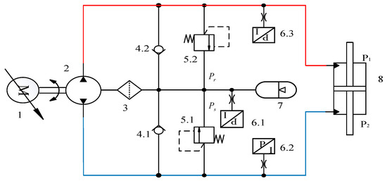
Figure 2.
Electrohydraulic servo pump control system working principle. 1. Servo motor; 2. Quantitative piston pump; 3. Drain filter; 4. Check valve; 5. Relief valve; 6. Pressure sensor; 7. Oil recharge accumulator; 8. Symmetric hydraulic cylinder.
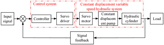
Figure 3.
Constant displacement variable speed control system frame diagram.
Taking into account the compressibility of oil, the pressure dynamics of the hydraulic cylinder can be written as:
where are the control volumes of the two cavities of the hydraulic cylinder, and and are the incipient volumes of the two cavities of the hydraulic cylinder; is the effective volumetric modulus of hydraulic oil; is the total intrinsic leakage related to the load pressure ; and are the patterning deviations of the dynamics, severally; is the oil supply flow into the hydraulic cylinder cavity and is the oil return flow out of the hydraulic cylinder cavity.
Taking into account oil compression, intrinsic and exterior leakages and other elements, the flow distribution characteristics of the quantitative pump are analyzed. and can be patterned as:
where is the total flow gain associated with the control input , and is defined as .
By defining the state variable as , the system can be written in state space formalization:
where:
Hydraulic cylinder leakage causes significant harm and failure, affecting safety and producing environmental pollution. Hydraulic cylinder leakage includes intrinsic and exterior causes, with the main causes being poor sealing and poor contact at the connection. To enhance tracking precision, it is assumed that intrinsic leakage is caused by circular and slot seals in the hydraulic cylinder, regarded as laminar flow combined with poor flow. Thus, the intrinsic leakage pattern is expressed as:
where and denote the compression coefficients of the circular, long and narrow seals, severally.
3. Enhanced LuGre Friction Pattern and System Remake Upion
3.1. Novel Continuous Differentiable Friction of Rest Pattern
General friction of rest patterns contains discontinuous sign functions. Many researchers have come up with approximating friction of rest using the inverse tangent function, or approximating the sign function laying the foundation of a hyperbolic tangent. A new type of continuously differentiable friction pattern laying the foundation of the hyperbolic tangent approximation can be described as [26]:
where represent the amplitude levels of disparate friction characteristics, and represent the form coefficients of friction characteristics. approximates the Coulomb friction; approximates the maximum friction of rest and represents the Stribeck effect of friction. represents the viscous friction term in the pattern. The curve characteristics of this static pattern, with respect to its velocity, are shown in Figure 4.
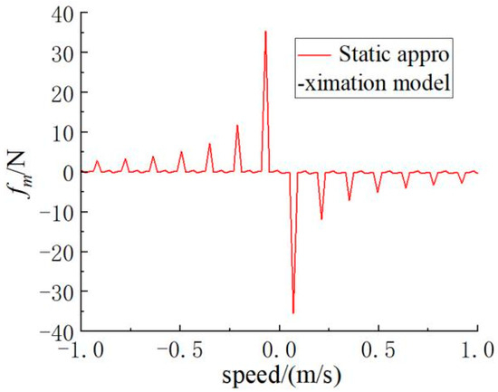
Figure 4.
New static pattern.
Since the hyperbolic tangent function is continuously smooth, using the hyperbolic tangent function instead of the discontinuous switching function can effectively reduce the buffering in the control process.
We define the friction pattern parameter as and its corresponding regressor as ; the friction pattern (7) can be parameterized to linearization:
3.2. Enhanced LuGre Friction Pattern and Reconstruction
The hydraulic pump itself has a zero dead zone nonlinear in it, and the motor has a low-speed jitter at zero speed, including pulse vibration, in it. According to the current analysis, the displacement of the pump is nonlinear, and the motor speed is also nonlinear. We analyze the micro-displacement position control of the pump-controlled AGC system, laying the foundation of the enhanced friction pattern while ignoring the dead zone.
This section enhances the conventional LuGre friction pattern using the continuously differentiable properties of the friction of rest pattern in Section 3.1.
To accurately pattern the friction term in the nonlinear pattern (4), the LuGre pattern was enhanced. The friction force is able to be described as . Where denote the mane stiffness, damping and viscous damping coefficient of the system, and is the relative velocity of motion.
The nonlinear function can be patterned as:
where represents the Coulomb and friction of rest forces; is the Stribeck velocity and sign is the standard symbolic function.
To avoid the inseparability of the LuGre pattern, it is necessary to remake the static Stribeck function in the LuGre pattern to devise a backstep method. Without a symbolic function, the static force is approximately:
where represents the friction of rest force, and and represent the amplitude levels of different friction characteristics. represents the shape coefficient of the friction characteristics.
As a matter of fact, the friction pattern (10) is capable of accurately approaching friction of rest and characterizing all behaviors of friction of rest. Thus, the nonlinear function can be modified using a continuously differentiable hyperbolic tangent function as follows:
A positive function A was defined to improve the discrete controller in the experiment. The enhanced LuGre pattern is expressed as:
For any constant , let and obtain the steady friction force .
Compare Equations (10) and (13) to obtain .
Combined with the enhanced intrinsic leakage and friction pattern, the dynamic equation for the entire system is represented as:
In this equation, and are known nonlinear functions, defined as:
There is parameter uncertainty in the pump control system, and there may be unknown constant values in the patterning deviation. The zero drift of the hydraulic cylinder position should be taken into account, defined as zero drift; then is the practical control voltage applied to the servo valve.
We define the unknown parameter set as and . Thus, the state space is able to be written as:
where and are the time-varying patterning deviations in the third and fourth equations, severally.
Hypothesis 1 (H1).
The expected tracking position instruction is bounded, and , .
Hypothesis 2 (H2).
The defined parameter set
satisfies:
where and are known, and , , where and are positive limited functions.
4. Devising a Self-Adapting Friction Compensation Controller
The parameters are time-varying, generally regarded as perturbations, which are mainly divided into intrinsic perturbations and exterior perturbations. Intrinsic perturbations include changes in oil temperature (causing changes in oil viscosity), changes in system pressure, changes in pattern parameters, etc. Taking the hydraulic cylinder as an example, in addition to the leakage coefficient and friction force, it will change with the temperature, pressure, wear and other perturbation conditions. The natural frequency of the hydraulic cylinder will also change with the different position of the piston (similar to the parallel connection of two hydraulic springs, the spring stiffness will change with the different position of the piston). The elastic modulus of the hydraulic oil itself will also be changed by temperature and the proportion of air mixed in, as well as exterior perturbations, such as load changes (especially load conditions that cannot be accurately predicted), various influencing elements brought by environmental conditions, etc. Taking into account the time-varying parameters, analyzing the inherent characteristics of the system and devising the compensation controller is another problem that we focus on.
For high-accuracy micro-displacement control of the system, self-adapting friction compensation laid the foundation of the enhanced LuGre pattern and was used to devise the controller, as shown in Figure 5.
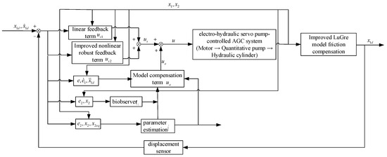
Figure 5.
Self-adapting friction compensation control block diagram of enhanced LuGre pattern.
4.1. Devising a Self-Adapting Friction Compensation Controller Laid the Foundation of Enhanced LuGre Pattern
The system equation has an unmatched parameter uncertainty; thus, it is imperative to devise the controller using the inversion method [30].
Step 1: Define the following deviation variables from system Equation (16):
where is the positive feedback gain.
From Equation (18):
Devising the controller in this step, the dual-observer is applied to calculate the diverse properties of state , to ensure that the observer is stable; the mapping function is applied to guarantee that the calculation of the observer is controlled.
The control function for dynamic Equation (19) has the following structural formalization:
where is the devised controller parameter, the devised comprehensive feedback gains and are sufficiently large enough to make the matrix a positive definite matrix .
The defined offset between the control function and virtual control import is expressed as :
where:
According to (21), is able to be devised to contain the subsequent stabilization conditions:
where is a devised controller parameter that is capable of being faculatively small and positive. is a robust controller, devised as:
where is an arbitrarily small function satisfying: .
The Lyapunov function is defined as .
Its time derivative is:
Step 2: According to the definition of ,
For the unknown parameter , the described parameter self-adapting law is used. Analogous to , the practical control law is devised as [29]:
where is the feedback gain; is the adjustable pattern compensation term with an online parameter self-adapting function; expresses the linear negative definite feedback term used to stabilize the nominal pattern of the system and is the enhanced nonlinear robust feedback term used to address patterning uncertainties. The integrated feedback gain is large enough to apply the matrix , a positive definite matrix .
The devised meets the following stabilization conditions:
where is a controller parameter that is capable of being arbitrarily small or positive.
As indicated in Equation (29), the devised is a robust controller; the robust term is devised as:
where is an arbitrarily small function satisfying .
4.2. Self-Adapting Controller Capacity
Theorem 1.
If the system has only parametric indeterminacy and nonlinear friction, the self-adapting function , which is the state observer of the projection type, learns the following:
where
and
are the learning gains, and the feedback gains
and
are sufficiently large enough to apply the matrix
positive definite:
The described control law (28) ensures that the signal of the entire closed-loop system is bounded. The gradual exportation tracking capacity can be obtained when is .
Define a Lyapunov function as:
Its derivative is:
laid the foundation of the equation and because , , and nonlinear gains and are normal numbers,
Because is always positive for ,
where is the smallest eigenvalue of the matrix . From Equation (37), and signal are bounded. As reported in [29], is bounded. The acceleration of the load is bounded; thus, the derivative of is bounded and the control input is bounded. Dynamics laid in the foundation of easily derive derivatives that are bounded; therefore, is consistently continuous. According to Barbalat’s lemma, when is , Theorem 1 is proven.
Theorem 2.
If the system has a time-varying patterning deviation, A, the described control law (28) guarantees that all signals of the closed-loop system are bounded. The positive definite Lyapunov function is bounded; its bound is:
where , and , , and the signal are bounded. As in the proof of Theorem 1, the boundedness of is proven.
5. Experimental Verification
To assess the capacity of the devised controller and study important issues in high-precision tracking control of the hydraulic system with nonlinear friction compensation [31], simulation experiments were conducted out to certify the precision capacity of the micro-displacement position control of the system in the pump-controlled AGC of a lithium battery pole plate mill. The equipment platform is shown in Figure 6. The dependability of the self-adapting friction compensation controller laid the foundation of the enhanced LuGre pattern and was certified by contrasting it with the conventional LuGre pattern controller, using a roller-formalization experiment on the negative electrode plate of a lithium battery. This paper relies on a pump-controlled AGC prototype to test and analyze engineering data. The pump control unit adopts the integrated structure, and one pump control unit is installed under the roll on the drive side and the operating side, respectively. The roll gap and rolling force are controlled by the displacement and output of the hydraulic cylinder. In the working process of the pole plate mill, according to the type of the pole plate, it can be divided into two rolling conditions: constant roll gap and constant rolling force, which correspond to the pump-controlled AGC position and high performance control mode of force. This paper studies the pump-controlled AGC position control mode.
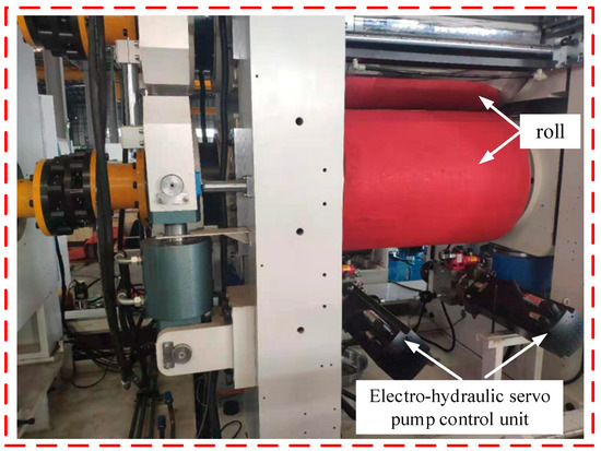
Figure 6.
Pump-controlled AGC equipment experimental system.
According to the rolling process of pole strip mill, the specific technical specifications are shown in Table 1. A Moog Electric servo pump unit (EPU) is selected for the servo motor pump group of pump-controlled AGC. The technical specifications of the EPU unit are shown in Table 2. Hydraulic cylinder indicators are shown in Table 3.

Table 1.
Pump-controlled AGC technical index requirements.
Table 2.
EPU technical indicators of pump-controlled AGC system.
Table 3.
Technical specifications of hydraulic cylinder for a pump-controlled AGC system.
The smooth motion instruction was selected as , and the maximum speed of the instruction was selected as 31.4 mm, as shown in Figure 7. An ALuGre self-adapting friction compensation controller laid the foundation of the enhanced LuGre pattern that is described within this section. ARCm is the friction self-adapting robust compensation controller that laid the foundation of the LuGre pattern.
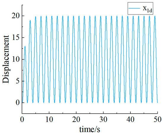
Figure 7.
Smooth motion instruction diagram.
To certify the low-speed tracking capacity of the described self-adapting friction compensation controller that laid the foundation of the enhanced LuGre pattern, the low-speed motion track was used in the experiment. Due to the low-speed of this command, the nonlinear friction force was mainly concentrated in the Stribeck effect region, making it difficult to track the general hydraulic servo system. Thus, nonlinear friction was the dominant factor affecting the tracking capacity. The effectiveness of the controller that laid the foundation of the described friction compensation was verified.
The ALuGre controller exhibited eminent transient tracking capacity. With an incipient deviation, the LuGre controller can quickly control the position; the tracking deviation was relatively small and the speed tracking was good, although there was a small deviation. The tracking capacity is shown in Figure 8 and Figure 9. The input was , and . The devised self-adapting robust sliding mode control can achieve good dynamic tracking capacity with parameter uncertainty and system indeterminacy.
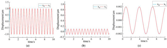
Figure 8.
(a–c) Low-speed tracking capacity–displacement.
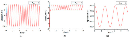
Figure 9.
(a–c) Low-speed tracking capacity–speed.
The low-speed tracking capacities of the ALuGre and conventional PID controllers are shown in Figure 10. The friction compensation in the described ALuGre controller can compensate for unknown effects, even with low-speed instructions and a strong nonlinear influence. Compared to a conventional PID controller, the steady-state deviation was smaller, due to parameter adaptation. The exportation position deviation of the hydraulic cylinder is shown in Figure 11. The steady-state error pairs of each controller are shown in Table 4. The steady-state deviation of the system can achieve ±0.1 μm with friction compensation self-adapting control of the ALuGre controller. The steady-state deviation is capable of achieving ±0.3 μm with the control strategy laid in the foundation of the LuGre pattern. The steady-state precision of the system using the conventional PID control strategy can achieve ±2.5 μm. Nevertheless, this method has a large steady-state deviation. These results indicate that the friction compensation self-adapting control strategy of the ALuGre controller can significantly enhance the control accuracy of the pump-controlled AGC system.
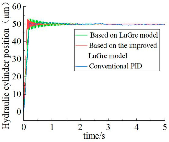
Figure 10.
Hydraulic cylinder piston displacement process.
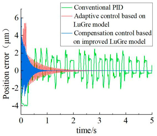
Figure 11.
Hydraulic cylinder exportation position deviation.
Table 4.
Comparison of steady-state errors of controllers.
6. Conclusions
To address the disadvantages of a controller laid in the foundation of a dynamic pattern (the strong assumption condition of the controller with a new continuously differentiable friction of rest pattern), an enhanced LuGre pattern was pioneered. Its Stribeck effect was replaced by a continuous differentiable function. A self-adapting friction compensation controller which laid the foundation of the enhanced LuGre pattern was devised. Laid in the foundation of the simulation platform of the pump control system, the ALuGre, LuGre and conventional PID controllers were devised and built. Compared to the simulation results, the described controller effectively compensated for the dynamic friction behavior and enhanced the low-speed tracking capacity. In practice, the described controller can be conveniently applied to other hydraulic systems. Nevertheless, its low-speed tracking capacity must be further enhanced for higher control precision of the pump-controlled AGC system.
This research is of vital consequence both in theory and practice. In terms of theoretical consequence, through investigation and demonstration of the theoretical system, this study not only enriched the empirical data of the position control of pump-controlled AGC laid in the foundation of a friction pattern, but also integrated a new architecture theory, providing a new perspective and supplementing past research on position control theory. This will promote the theoretical development of the pump-controlled AGC field and fill the shortcomings of previous pump-controlled position control research.
Author Contributions
Funding acquisition, G.C., K.L. and M.W.; formal analysis, K.W. and T.Z.; methodology, G.C., K.W. and F.W.; project administration, G.C.; resources, G.C. and K.W.; software, K.W.; writing—original draft, K.W.; writing—review and editing, K.W. and G.C.; supervision, K.W. and G.C. All authors have read and agreed to the published version of the manuscript.
Funding
This research was funded by the National Natural Science Foundation of China (Grant No. 52275066), the Natural Science Foundation of Xinjiang Uygur Autonomous Region (2022D01A51) and the Natural Science Foundation of Xinjiang Uygur Autonomous Region (2022D01B135).
Data Availability Statement
Data are contained within the article.
Conflicts of Interest
The authors declare no conflicts of interest.
References
- Wong, R.H.; Wong, W.H. Devise of Dual-Axial Electrohydraulic Servo Pump-Controlled Folding Machine. Chin. Soc. Mech. Eng. 2017, 38, 367–372. [Google Scholar]
- Zhang, C.; Wang, S. An Article Indicator for Mechanical Failure and Life Prediction Laid the Foundation of Debris Monitoring. IEEE Trans. Reliab. 2017, 66, 161–169. [Google Scholar]
- Fu, Y.L.; Han, X.; Yang, R.R.; Qi, H. Review on devise methods of electro-hydrostatic actuator. J. Beijing Univ. Aeronaut. Astronsutics 2017, 43, 1939–1952. [Google Scholar]
- Hao, Y.; Xia, L.; Ge, L.; Li, Z.; Zhao, B.; Quan, L. Control and Simulation Analysis of Energy Efficient Hydraulic-Electric Hybrid Linear Driving System. Chin. Hydraul. Pneum. 2020, 7, 49–54. [Google Scholar]
- Maghareh, A.; Silva, C.E.; Dyke, S.J. Parametric pattern of servo-hydraulic actuator coupled with a nonlinear system: Experimental validation. Mech. Syst. Signal Process. 2018, 104, 663–672. [Google Scholar] [CrossRef]
- Jiao, Z.X.; Yao, J.Y. Nonlinear Control of Electrohydraulic Servo System; Science Press: Beijing, China, 2016; pp. 100–102. [Google Scholar]
- Achten, P.; Mommers, R.; Potma, J.; Achten, J. Experimental Investigation of a Hydrostatic Bearing Between Barrels and Port Plates in Floating Cup Axial Piston Pumps. In Proceedings of the BATH/ASME 2020 Symposium on Fluid Power and Motion Control, Virtual, 9–11 September 2020. [Google Scholar]
- Sayed, M.; Habibi, R. Inner-Loop Control for Electrohydraulic (EHA) Actuation Systems. In Proceedings of the Dynamic Systems and Control Conference DSCC 2009, Hamilton, ON, Canada, 27–29 June 2009; Department of Mechanical Engineering, McMaster University: Hamilton, ON, Canada, 2010. [Google Scholar]
- Helian, B.; Yao, B.; Chen, Z.; Yang, C. Deviseing an enhanced Controller for a Pump Direct Driven Electrohydraulic System Using a Nonlinear Flow Mapping. In Proceedings of the Symposium on Fluid Power and Motion Control, Longboat Key, FL, USA, 7–9 October 2019; pp. 1–7. [Google Scholar]
- Chao, Q.; Zhang, J.; Xu, B.; Huang, H.; Pan, M. A Review of High-Speed Electro-Hydrostatic Actuator Pumps in Aerospace Applications: Challenges and Solutions. J. Mech. Devis. 2019, 141, 050801(1)–050801(13). [Google Scholar] [CrossRef]
- Wei, L.; Burton, R.; Habibi, S. Investigation of a High Precision Hydrostatic Actuation System: How Nonlinearities Affect Its capacity. In Proceedings of the ASME International Mechanical Engineering Congress & Exposition, Seattle, DC, USA, 11–15 November 2007. [Google Scholar]
- Lin, Y.; Shi, Y.; Burton, R. patterning and Robust Discrete-Time Sliding-Mode Control devise for a Fluid Power Electrohydraulic Actuator (EHA) System. IEEE/ASME Trans. Mechatron. 2013, 18, 1–10. [Google Scholar] [CrossRef]
- Hu, J.; Sun, Y.; Zhang, Z. Dyanmic analysis of asymmetrical working mechanism with 2 servo-input for mechanical servo press. J. Plast. Eng. 2020, 27, 221–227. [Google Scholar]
- Wei, S.; Li, G. Study oI Torque Control oI Rotating Hydro-elastic Actuator laid the foundation of Robust intrinsic-loop Compensator. Mach. Tool Hydraul. 2020, 48, 104–108. [Google Scholar]
- Nam CN, D.; Yoon, I.J.; Ahn, K.K. Position-control of Electro hydrostatic actuator (EHA) using a modified back stepping controller. J. Drive Control. 2012, 9, 16–22. [Google Scholar] [CrossRef][Green Version]
- Chai, H.; Zhang, Z.; Zhao, D.; Li, W. Study on Dual Pump Direct Drive Volume Control Electrohydraulic Servo System. In Proceedings of the 2019 IEEE 8th International Conference on Fluid Power and Mechatronics (FPM), Wuhan, China, 10–13 April 2020. [Google Scholar]
- Auranne, H.; Koitto, T.; Calonius, O.; Minav, T.; Pietola, M. Direct Driven Pump Control of Hydraulic Cylinder for Rapid Vertical Position-control of Heavy Loads: Energy Efficiency Including Effects of Damping and Load Compensation. In Proceedings of the BATH/ASME 2018 Symposium on Fluid Power and Motion Control, Bath, UK, 12 September 2018. [Google Scholar]
- Helian, B.; Chen, Z.; Yao, B. Precision Motion Control of a Servo Motor-Pump Direct Drive Electrohydraulic System with a Nonlinear Pump Flow Mapping. IEEE Trans. Ind. Electron. 2019, 67, 8638–8648. [Google Scholar] [CrossRef]
- Luo, G.; Gorges, D. Patterning and self-adapting Robust Force Control of a Pump-Controlled Electrohydraulic Actuator for an Active Suspension System. In Proceedings of the Conference on Control Technology and Applications (CCTA), Hong Kong, China, 19–21 August 2019; pp. 592–597. [Google Scholar]
- Zad, H.S.; Ulasyar, A.; Zohaib, A. Robust pattern Predictive position-control of direct drive electrohydraulic servo system. In Proceedings of the International Conference on Intelligent Systems Engineering (ICISE), Islamabad, Pakistan, 15–17 January 2016. [Google Scholar] [CrossRef]
- Van Nguyen, T.; Ha, C. Sensor Fault-Tolerant Control Devise for Mini Motion Package Electrohydraulic Actuator. Processes 2019, 7, 89. [Google Scholar] [CrossRef]
- Yin, X.; Zhang, W.; Jiang, Z.; Pan, L. Self-adapting robust integral sliding mode pitch angle control of an electrohydraulic servo pitch system for wind turbine. Mech. Syst. Signal Proc. 2018, 9, 1–15. [Google Scholar]
- Ren, G.; Esfandiari, M.; Song, J.; Sepehri, N. Position-control of an Electrohydrostatic Actuator with Tolerance to intrinsic Leakage. IEEE Trans. Control Syst. Technol. 2016, 24, 2224–2232. [Google Scholar] [CrossRef]
- Ren, G.; Song, J.; Sepehri, N. Fault-Tolerant Actuating Pressure Controller devise for an Electrohydrostatic Actuator Experiencing a Leaky Piston Seal. J. Dyn. Syst. Meas. Control. 2017, 139, 061004. [Google Scholar] [CrossRef]
- Guo, Q.; Zhang, Y.; Celler, B.G.; Su, S.W. State-Constrained Control of Single-Rod Electrohydraulic Actuator With Parametric indeterminacy and Load perturbation. IEEE Trans. Control. Syst. Technol. 2017, 26, 2242–2249. [Google Scholar] [CrossRef]
- Zhang, M. Low Speed Research of TMT Three-mirror AC Servo System; Graduate School of Chinese Academy of Sciences, Changchun Institute of Optics, Fine Mechanics and Physics: Changchun, China, 2016. [Google Scholar]
- Li, X.; Zhu, Z.C.; Rui, G.C.; Cheng, D.; Shen, G.; Tang, Y. Force Loading Tracking Control of an Electro-Hydraulic Actuator Laid the Foundation of a Nonlinear self-adapting Fuzzy Backstepping Control Scheme. Symmetry 2018, 10, 155. [Google Scholar] [CrossRef]
- Makkar, C.; Dixon, W.E.; Sawyer, W.G.; Hu, G. A New Continuously Differentiable Friction Pattern for Control Systems Devise. In Proceedings of the IEEE/ASME International Conference on Advanced Intelligent Mechatronics, Monterey, CA, USA, 11–15 January 2005; pp. 600–605. [Google Scholar]
- Yao, J.; Deng, W.; Jiao, Z. Self-adapting Control of Hydraulic Actuators with LuGre Pattern Based Friction-Compensation. IEEE Trans. Ind. Electron. 2015, 62, 6469–6477. [Google Scholar] [CrossRef]
- Ahn, K.K.; Nam, D.N.C.; Jin, M. Self-adapting Backstepping Control of an Electrohydraulic Actuator. IEEE/ASME Trans. Mechatron. 2014, 19, 987–995. [Google Scholar] [CrossRef]
- Wang, K.; Chen, G.; Zhang, T. Pump-Controlled AGC Micro-Displacement Position Control of Lithium Battery Pole Strip Mill Based on Friction Model. Processes 2023, 11, 2587. [Google Scholar] [CrossRef]
Disclaimer/Publisher’s Note: The statements, opinions and data contained in all publications are solely those of the individual author(s) and contributor(s) and not of MDPI and/or the editor(s). MDPI and/or the editor(s) disclaim responsibility for any injury to people or property resulting from any ideas, methods, instructions or products referred to in the content. |
© 2024 by the authors. Licensee MDPI, Basel, Switzerland. This article is an open access article distributed under the terms and conditions of the Creative Commons Attribution (CC BY) license (https://creativecommons.org/licenses/by/4.0/).