Article

Enhancing Grid-Forming Converters Control in Hybrid AC/DC Microgrids Using Bidirectional Virtual Inertia Support

1
Department of Electrical Engineering, Faculty of Engineering, Aswan University, Aswan 81542, Egypt
2
Department of Electrical Power Engineering and Mechatronics, Tallinn University of Technology, 19086 Tallinn, Estonia
3
LEVRES Laboratory, Department of Electrical Engineering, El-Oued University, El-Oued 3900, Algeria
4
Department of Mechanical Engineering, Faculty of Engineering, University of Tabuk, Tabuk 47913, Saudi Arabia
5
Wolfson Centre for Magnetics, School of Engineering, Cardiff University, Cardiff CF24 3AA, UK
6
Electrical Engineering Department, School of Engineering, Al-Baha University, Al-Baha 7738-65799, Saudi Arabia
*
Authors to whom correspondence should be addressed.
Processes 2024, 12(1), 139; https://doi.org/10.3390/pr12010139
Submission received: 8 November 2023 / Revised: 31 December 2023 / Accepted: 3 January 2024 / Published: 5 January 2024
(This article belongs to the Section Energy Systems)

Abstract

:
This paper presents a new grid-forming strategy for hybrid AC/DC microgrids using bidirectional virtual inertia support designed to address weak grid conditions. The stability of hybrid AC/DC microgrids heavily relies on the AC mains frequency and the DC-link voltage, and deviations in these factors can lead to undesirable outcomes such as load curtailments and power system congestions and blackouts. This paper introduces a unique approach that leverages bidirectional virtual inertia support to enhance the stability and reliability of hybrid AC/DC microgrids under weak grid conditions. The proposed strategy employs virtual inertia as a buffer to mitigate rapid changes in DC-link voltage and AC frequency, thereby enhancing system stability margins. This strategy significantly contributes to a more stable and reliable grid operation by reducing voltage and frequency fluctuations. A standard hybrid AC/DC microgrid configuration is used to implement the bidirectional virtual inertia support, where a bidirectional interlinking converter control is adjusted to deliver inertia support to both the AC and DC subgrids. This converter utilizes the DC grid voltage and AC grid frequency as inputs, effectively managing active power balance and implementing auxiliary functions. Extensive simulations are conducted under weak grid conditions and standalone mode to validate the effectiveness of the proposed strategy. The simulation results demonstrate a remarkable improvement in frequency nadir, rate-of-change-of-frequency (RoCoF), and DC bus voltage deviation in the hybrid AC/DC microgrids. The bidirectional virtual inertia support substantially reduces voltage and frequency fluctuations, enhancing the microgrid stability and resilience. There is an improvement of over 45% and 25% in the frequency deviation and voltage deviation, respectively, achieved through implementing the proposed control strategy.

1. Introduction

The increasing global concern about climate change and the rapid depletion of fossil fuel reserves have necessitated a swift transition toward renewable energy resources in modern power systems [1]. This transition responds to environmental and sustainability concerns and strategically moves society toward energy independence and security. Distributed energy resources (DERs), such as photovoltaic (PV), wind turbines (WTs), and energy storage systems (ESSs), are progressively integrated into microgrids (MGs). This integration aims to achieve higher penetration levels of renewable energy and enhance power system reliability, resilience, and efficiency [2].
In conventional power systems, synchronous generators interact and operate at the same angular speed, known as the synchronous speed, defining the grid frequency. They mainly act as the primary source of forming the grid. These generators play a crucial role in maintaining the stability of the power system. Any frequency alteration due to a power imbalance between supply and demand causes these generators to autonomously adjust their speed, causing the grid frequency variations [3]. This adjustment allows generators to release or absorb energy into or from the power grid, thereby partially compensating for transient power mismatches. The quantification of these phenomena can be expressed in units of kinetic energy of the synchronous generators, commonly referred to as power system inertia [4].
However, the dynamics of power systems are changing with the increasing integration of renewable energy sources (RESs). Most RESs, like wind and PV energy sources, are connected to the power grid through power electronic converters. Unlike synchronous generators, these grid-tied power converters typically operate at the maximum power point tracking (MPPT) mode to maximize the output energy, contributing no inertia to the system. These power conversion systems do not possess any kinetic energy that can be utilized as rotational inertia [5,6].
As more synchronous generators are phased out and replaced with power converters, the overall power system becomes increasingly inertia-less. The decrease in the power system inertia deteriorates the stability and controllability of the power grid. Without adequate inertia, the grid frequency or rate-of-change-of-frequency (RoCoF) may surpass acceptable limits during severe grid disturbances. This can result in generation tripping, unscheduled load shedding, or even complete system failures [7].
Virtual synchronous machines (VSMs) have emerged as an effective method for adding virtual inertia to the power system by controlling the power electronic converters [8]. The concept of VSMs is particularly relevant in the smart grid, where power electronic converters play a dominant role, but strict requirements are imposed on their control strategies to preserve stability and controllability [9]. The VSM concept offers decentralized control schemes for power converters, providing grid support and allowing for a seamless transition between grid-connected or islanded operations [10,11]. This enables power electronic converters to operate with features similar to synchronous generators. A specific VSM implementation and its mathematical model are presented in detail in [12].
The control strategy of VSM includes (1) enhanced frequency regulation suitable for microgrids, (2) improved dual droop control between the AC frequency and the DC side energy storages, and (3) provisions for large-signal system stability [13]. Microgrids can incorporate distributed generation, loads, and energy storage. Our utility grids predominantly employ AC, so AC microgrids have attracted substantial interest [14]. Since most DERs and common loads such as lighting and electric vehicles connect with DC, adopting a DC microgrid could improve energy conversion efficiency. Consequently, a hybrid AC/DC MG has been proposed, amalgamating the benefits of both AC and DC systems [15,16].
Hybrid AC/DC MG provides more dependable power from AC and DC subgrids, especially for suburban regions. Supported by bidirectional interlinking converters (BICs), distributed subgrids are interconnected to form a comprehensive small-scale electrical system [17]. Microgrids can operate in grid-connected and islanded modes, providing the end users flexibility, energy supply security, and improved power quality [18,19]. During normal operation, energy can flow flexibly via the BIC between the two subgrids [20]. The surplus energy in the AC or DC sectors is adequately utilized for system operation [21,22]. Owing to its inherent advantages, a hybrid system includes AC and DC grid characteristics, which can cater to the demands of various loads and serve as a source of inertia provision.
Various frequency regulation strategies have been derived to improve the inertia of hybrid MGs. Since the rotational mechanism of synchronous generators directly provides inertia, these generators can be run in parallel on the generation side to augment system inertia. However, deploying multiple generators is expensive, and maintaining a substantial spinning reserve is inefficient [23]. A key challenge in controlling hybrid AC/DC MGs is maintaining the stability and power sharing among DERs, especially under transient conditions, such as load variations, fault scenarios, and fluctuations in the output of renewable energy sources [24]. One approach to address this challenge is through virtual inertia support (VIS), which can enhance the dynamic response of an MG and improve its stability [25]. VIS emulates the behavior of synchronous generators by providing a transient power injection proportional to the RoCoF, thereby mitigating the frequency and voltage deviations caused by disturbances in the system.
In the context of generators, it is essential to note that inertia is not readily available when in cold reserve mode, and additional time for restarting is necessary. From both economic and efficiency standpoints, bolstering inertia through generators is not prudent [26,27]. Several studies have proposed the utilization of ESSs like ultracapacitors or batteries for inertia compensation to overcome this limitation [28]. Current approaches to VIS predominantly focus on either AC or DC grids. Moreover, these methods often employ additional energy storage units to emulate inertia, but the high cost of installing such units penalizes their wider adoption [29,30]. In [31], DC capacitors of power converters are utilized to provide limited inertia emulation capability. Consequently, the existing VIS characteristics in hybrid AC/DC grids are addressed inadequately. In order to provide a clearer understanding of the differences among the various research studies that were examined, Table 1 presents a comprehensive comparison of these investigations.
A weak grid denotes an electrical power system with low electrical impedance, insufficient voltage regulation, and restricted capacity to manage power fluctuations. In addition, weak grids are susceptible to voltage and frequency fluctuations, power quality issues, and potential blackouts, which can have severe consequences for residential and commercial consumers. Hybrid AC/DC microgrids offer a promising solution to these challenges by providing local power generation, energy storage, and advanced control capabilities that support and stabilize weak grids [36]. It is recognized that weak grids, characterized by large grid impedances, can render three-phase grid-connected power converters unstable due to the resonance caused by high-order passive filters [37], interaction among multiple power converters [38], and the impact of the phase-locked-loop (PLL) on current control [39]. This paper identifies another factor contributing to instability: the strong coupling between control loops (specifically, the dq-frame control systems) and the differential operator. This coupling can lead to instability in grid-connected power converters implementing VIS with capacitors or ultracapacitors.
This paper presents a comprehensive grid-forming (GF) control strategy in hybrid AC/DC MG with bidirectional virtual inertia support. The proposed control strategy aims to ensure stable operation and optimal power sharing among DERs under various operating conditions while also enhancing the transient response and fault ride-through capability of the MG. The effectiveness of the proposed control strategy is validated through extensive simulation tests. The main contributions of this paper can be summarized as the following:
  • Development of a new control strategy for GF in hybrid AC/DC microgrids with bidirectional virtual inertia support that maintains stability and power sharing among DERs under various operating conditions.
  • Demonstrate that the proposed grid-forming strategy can be utilized in standalone and grid-connected modes for AC/DC microgrids.
  • Validation of the proposed control strategy through extensive simulation tests demonstrates its effectiveness in enhancing the transient response, weak grid operation, and overall hybrid AC/DC MG performance.
The remainder of this paper is organized as follows. Section 2 presents the system configuration and mathematical modeling of the hybrid AC/DC MG. Section 3 describes the proposed control strategy, including the design of the proposed control strategy in grid-forming hybrid AC/DC MG for the bidirectional VIS. Section 4 presents the results obtained from the simulation tests and the performance analysis of the proposed control strategy. Finally, Section 5 concludes the paper and suggests future research directions related to the current study.

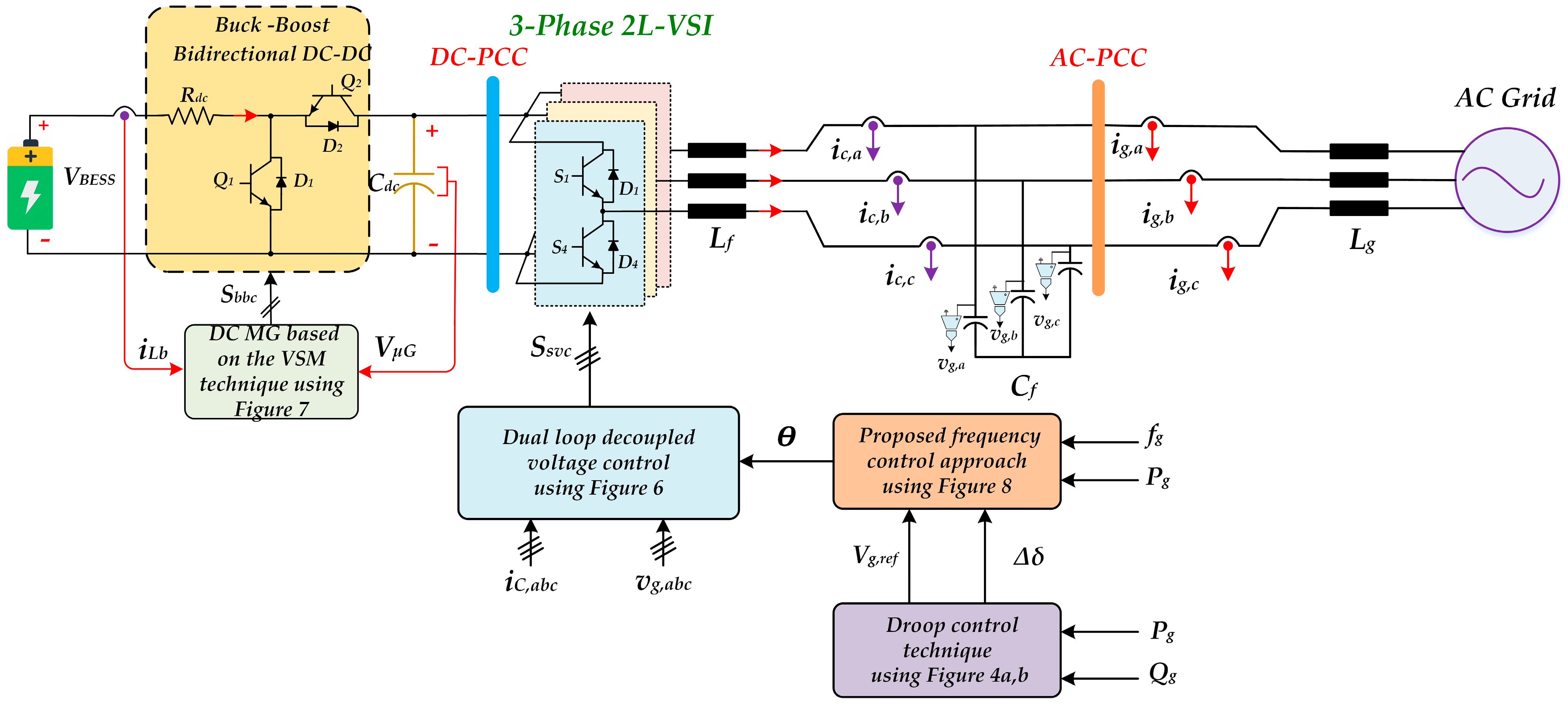
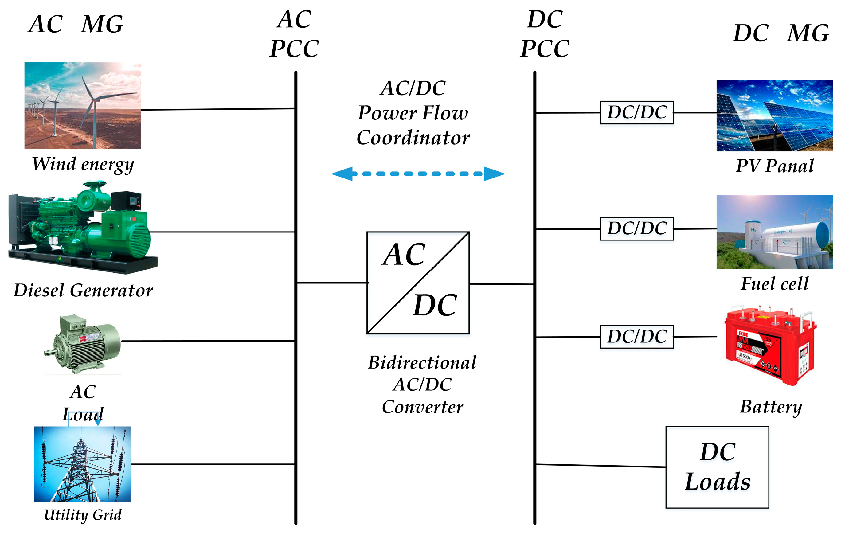
2. Configuration of the Studied Hybrid AC/DC Microgrid

The hybrid AC/DC MG system consists of an AC subgrid, a DC subgrid, and a bidirectional power converter interfacing the two subgrids. Figure 1 provides a schematic diagram of the hybrid AC/DC MG configuration, illustrating the key components and their interconnections. The AC subgrid includes DGs, such as synchronous generators or wind turbines, loads, and energy storage systems connected to the corresponding point of common coupling (PCC). In contrast, the DC subgrid contains PV panels, battery energy storage systems (BESS), and DC loads. The bidirectional power converter enables power flow between the AC and DC subgrids while supporting the virtual inertia for the AC subgrid.
In a hybrid AC/DC MG, integrating both AC/DC power sources and loads is challenging due to the differences in their electrical characteristics. Grid frequency and DC-link voltage fluctuations can affect their stability and performance. By providing bidirectional VIS, the proposed method would help maintain the stability and performance of the hybrid AC/DC MG by quickly responding to any grid frequency or DC-link voltage disturbances.
The control strategy aims to enhance the dynamic stability of the hybrid AC/DC MG by providing bidirectional virtual inertia support through the VSM control algorithm. The proposed VSM control is applied to the converter, interfacing the AC and DC subgrids. The control algorithm consists of three main components:
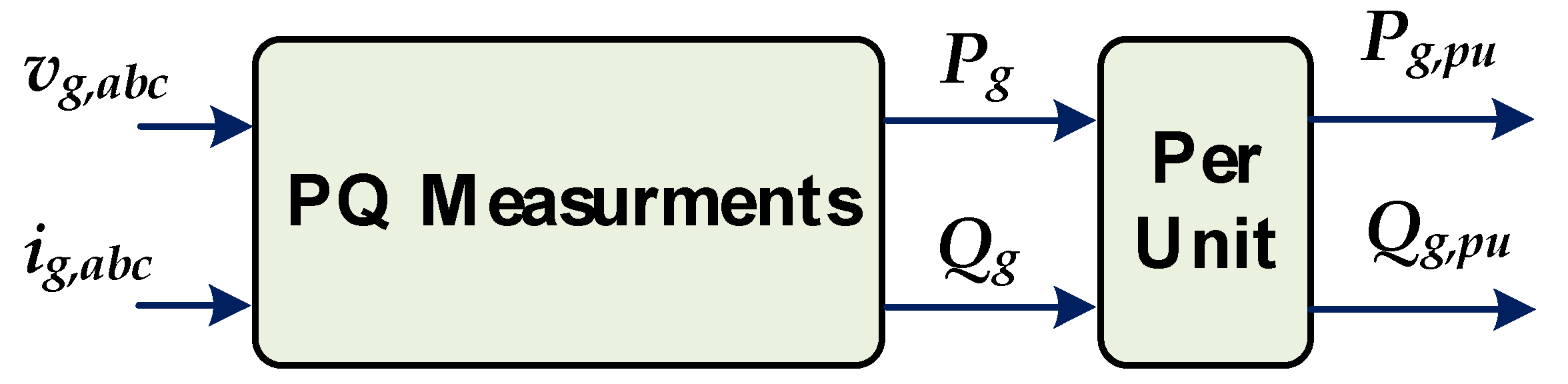
  • Power controller for regulating the active and reactive power exchange;
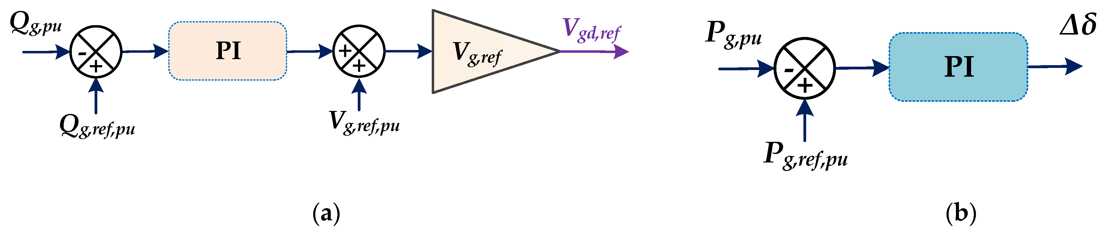
  • Frequency and voltage droop controller for power sharing among DERs;
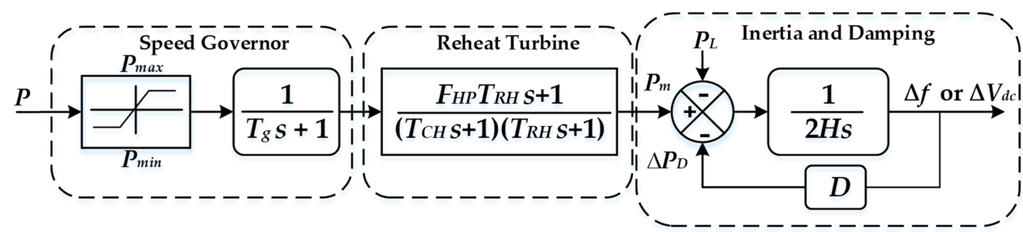
  • Virtual inertia emulator for enhancing transient stability.
The virtual inertia concept refers to emulating the physical inertia of traditional synchronous generators in power systems using power electronic devices such as inverters. Inertia is an essential property of power systems that helps to maintain frequency stability during transient events. The virtual inertia concept aims to overcome this challenge by using control algorithms that adjust the output power of inverters based on the RoCoF in the power system. This additional power injection helps to dampen frequency deviations and improve system stability, reproducing the behavior of synchronous generators with physical inertia. The control schematic illustrating the effective implementation of inertia for system frequency regulation is depicted in Figure 2, where FHP, TCH, and TRH are the coefficients for the reheat turbine. At the same time, Tg represents the time constant of the speed governor. The definition of the electromechanical characteristic of the synchronous generator could be defined as [40]
D f + 2 H d f d t = P i n P L
where H and D are coefficients that represent the frequency-dependent load-lumped inertia and damping factor, respectively. The inputs, i.e., mechanical and load power values, are designated as Pin and PL, respectively. At the same time, the frequency deviation, denoted as Δf, is determined by the coefficient of inertia and the difference between Pin and PL [40]. In physical terms, this refers to the alteration in the amount of power absorbed by motor loads based on frequency changes caused by fluctuations in motor speeds. The additional active power (ΔPD) is injected into the grid based on the RoCoF and the virtual inertia constant (H).
The damping power in the power system is expressed as [40]
P D = D f  
By substituting ΔPD in Equation (1), we obtain a new expression that emulates the behavior of a synchronous generator with physical inertia (note that Pin = Pm):
2 H d f d t = P m P L P D
This equation shows how the virtual inertia control algorithm adjusts the output power of the inverter based on RoCoF to imitate the behavior of traditional synchronous generators and maintain frequency stability in power systems. Under steady-state conditions, the mechanical input power of Pm,ref equals the sum of the load power, PL,ref, and the damping power, PD,ref. As a result, the system frequency remains constant, i.e., ∆f is equal to zero.
Subtracting the steady-state values from Equation (2) yields Equation (4), which describes the small changes in frequency regulation, also known as the small-signal behavior.
P L = P m P D 2 H d f d t
Equation (4) indicates that any variation in the load power (∆PL) should be counterbalanced by deviation of the input mechanical power (∆Pm), the inertia power of 2H(d∆f/dt), and damping power (∆PD). Hence, a significant power difference during load-shifting events within the AC subgrid can result in a substantial deviation in frequency (∆f). This can potentially cause issues with the frequency stability, especially if the inertia coefficient (H) is small due to the high penetration rate of the RESs.
Likewise, Equation (5) represents the swing equation for the DC subgrid.
P L = P m P D 2 H d V d c d t
where V d c is the DC bus voltage deviation. When the inertia coefficient is low, the deviation in the DC bus voltage V d c   is more likely to surpass the acceptable range and cause instability.

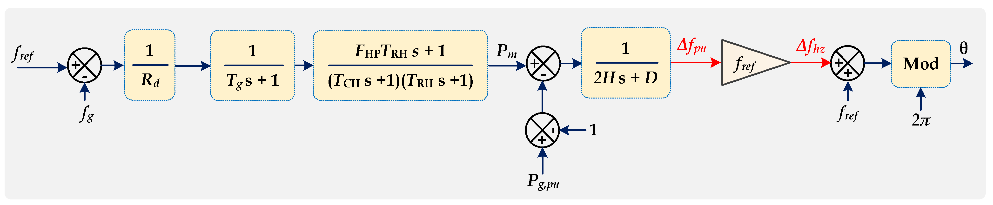
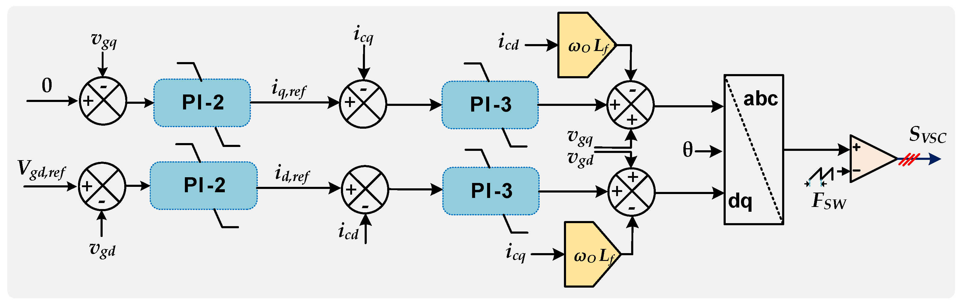
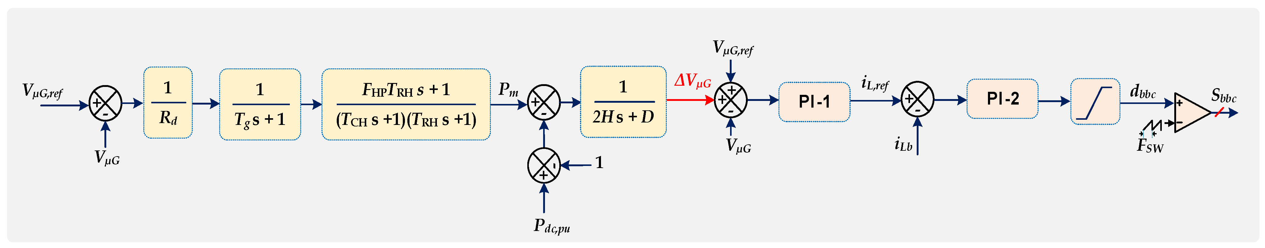
3. Proposed Control Strategy for Grid-Forming Converters of Hybrid AC/DC MG

Considering the constraints of the standalone hybrid AC/DC MG, the suggested approach of implementing virtual inertia control is expanded to grid-forming to enhance system stability. The proposed GF approach for the hybrid AC/DC MG is sketched in Figure 3. It utilizes a two-level, three-phase voltage source converter (VSC) with an output LCL filter. The possible instabilities in a weak grid are investigated. The VSC could be represented as an ideal voltage source vg,abc feeding power to the grid and a grid inductor Lg connected in series. The voltage drop across Lg can be severe in the case of weak grids (high value of Lg), causing the observed voltages at the PCC vg,abc to differ considerably from the ideal grid voltages vg,abc. The circuit breaker connecting the MG to the main grid is severed when operating in the islanded mode. Fuel cells, battery energy storage devices, and other dispersed resources could be used to create the DC link via the BIC.
In the case of inductance-dominated line impedance, the power angle mostly determines the active power P. Still, the output voltage magnitude Vgd primarily determines the reactive power Q. Droop control can simply cover P and Q regulation functions. To simplify the hierarchical control of an MG, active and reactive power references (Pref, Qref) were included in the control scheme illustrated in Figure 4.
In Figure 4a, the P-δ droop method produces the reference angular frequency of output voltage (wref) and its corresponding rotating angle (δref). The P-δ droop control can be reformulated as
δ = δ δ r e f = K d ( P g , p u P g , p u , r e f )
where Kd represents the droop coefficient of the P–δ droop.
Meanwhile, the Q-Vgd droop method generates the output voltage magnitude in the d-axis direction (Vgd,ref). This strategy helps maintain voltage stability in the grid, ensuring optimal power distribution, as illustrated in Figure 4b. Furthermore, Figure 5 illustrates the per-unit representation of the measured active and reactive powers. The reactive power-voltage droop control can be represented as:
V g , p u V g ,   p u , r e f = K v ( Q g , p u Q g , p u , r e f )
where Kv represents the droop coefficient of the Q–Vgd droop.
Typically, grid-tied converters require PLLs, which enable synchronization with the PCC. In the GF mode, the VSC is a voltage source that generates a voltage of the required magnitude and frequency. Figure 6 illustrates a model of synchronous-frame-based PLLs from [41]. The following equation describes the relationship between the converter voltages vc,abc and the grid voltages vg,abc in the synchronous dq-frame [40]:
V c d t = v g d t + L f d i c d ( t )   d t w o L f i c q ( t ) V c q t = v g q t + L f d i c q ( t )   d t + w o L f i c d ( t )
where Vcd(t) and Vcq(t) represent the d- and q-axis components of converter voltages, respectively; vgd(t) and vgq(t) denote the d- and q-axis components of grid voltages, respectively; icd(t) and icq(t) represents the d- and q-axis components of converter currents, respectively; Lf denotes filter inductance. In addition, wo denotes the fundamental angular frequency.
The dual loop decoupled voltage control of the BIC is illustrated in Figure 6, where the outer voltage loop depends on voltage measurements vgq and vqd at the PCC, which are compared to the references Vgq,ref and Vgd,ref, respectively, using the proportional-integral regulator PI-2. In order to achieve unity power factor operation, it is necessary to keep the voltage Vgq,ref equal to zero. The control errors generate the current reference iq,ref and id,ref. An Inner current control loop for GF control regulates icd and icq using the PI-3 regulators. The PWM provides gate control commands, which are delivered to the switches of the VSC, resulting in the generation of the desired voltage (see Equation (8)).
The proposed GF control for the case-study hybrid AC/DC MG is divided into two parts, as shown in Figure 6, Figure 7 and Figure 8: a DC-link voltage control and frequency control, where ∆Vdc is calculated using the control frame using inertia in Figure 7, and ∆f is calculated using the AC subgrid control in Figure 8. The DC-link voltage error ∆Vdc is applied to a PI controller to generate the reference current of the output battery. To eliminate the DC-link and frequency deviations, the sum of Pm,pu, and Pdc,pu is set equal to zero. The notations Ssvc and Sbbc in Figure 6 and Figure 7 designate the AC subgrid and BIC switching signals, respectively.
The observations show that the proposed approach enables the control strategy to offer bidirectional virtual inertia support. By altering the power flow through the BIC, virtual inertia is exchanged between the DC and AC subgrids, fundamentally improving frequency stability regarding frequency nadir and RoCoF. Furthermore, implementing VSM inertia enhancement control under weak grid conditions can support increased virtual inertia. The AC and DC grids experience increased inertia, comparable to the interconnection of multiple power systems using the proposed approach. This increased inertia enhances the stability of both grids during the different events. However, they are also affected by frequency events occurring in the other grid. For instance, without the proposed method, the AC grid would not respond to DC grid faults and vice versa. With the implementation of the proposed method, the AC grid transfers power to the DC grid during DC grid faults, resulting in increased inertia in both grids.
The GF function is implemented by the adjustment of the power reference, Pac,ref, according to Equation (9), based on the relative frequency error (∆f/fref) and the relative DC voltage error (∆VDC/Vdc,ref).
P a c , r e f = f f r e f + V D C V d c , r e f k p + k i s
The gain factors kp and ki in the PI controller define the system response to these errors. This allows the converters in the AC and DC subgrids to respond to changes in frequency and voltage and adjust their output power accordingly. Additionally, using a BIC, power flow can be adjusted between the AC and DC subgrids in response to faults or other disturbances, further enhancing the grid-forming ability of the system. This helps improve the power system’s resilience by allowing it to respond to and recover from disturbances more effectively. By implementing this control strategy, the AC and DC subgrids effectively become grid-forming, contributing to the overall stability of the power system. This is particularly important in power systems with a high penetration of renewable energy resources, as these systems often lack the physical inertia of traditional synchronous generators.
In essence, the grid-forming behavior of the system is greatly enhanced under your proposed method, thus improving the overall stability and resilience of the power system.

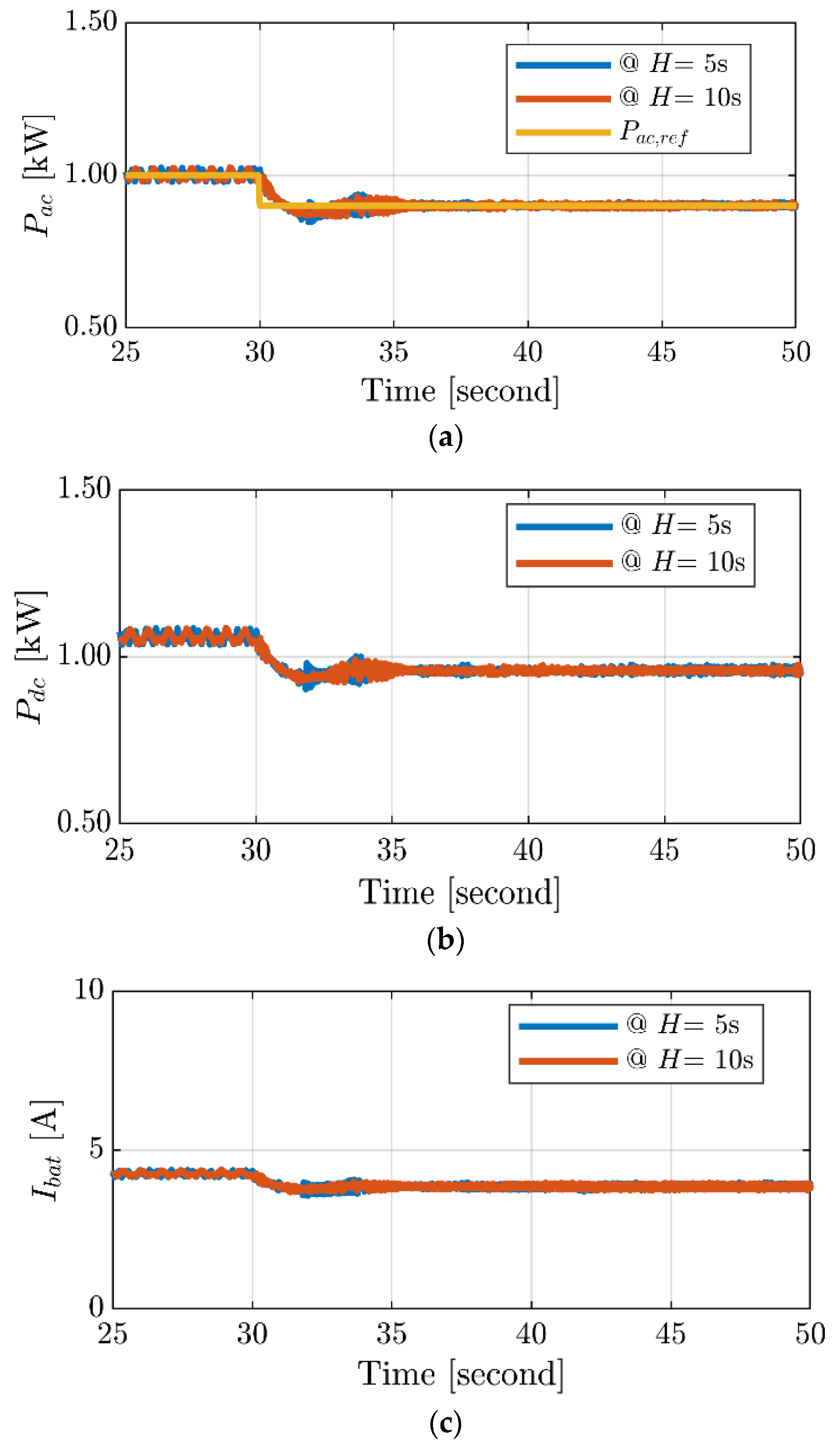
4. Simulation Results and Discussion

The proposed new control strategy for the GF hybrid AC/DC microgrids with bidirectional virtual inertia support was tested using MATLAB/Simulink. A hybrid AC/DC MG model was built, comprising conventional AC and DC power sources interconnected through VSC. At the same time, the control strategies were implemented using the Simulink control system toolbox. Table 2 presents the system parameters encompassing the AC and DC subgrids. Beyond the VSM, Table 3 outlines the parameters for other components within the system. The transition between grid-connected and islanded modes is seamlessly achieved with the proposed strategy. The performance of the proposed strategy was evaluated under a variety of two operational scenarios: (i) grid-connected mode and (ii) standalone mode.

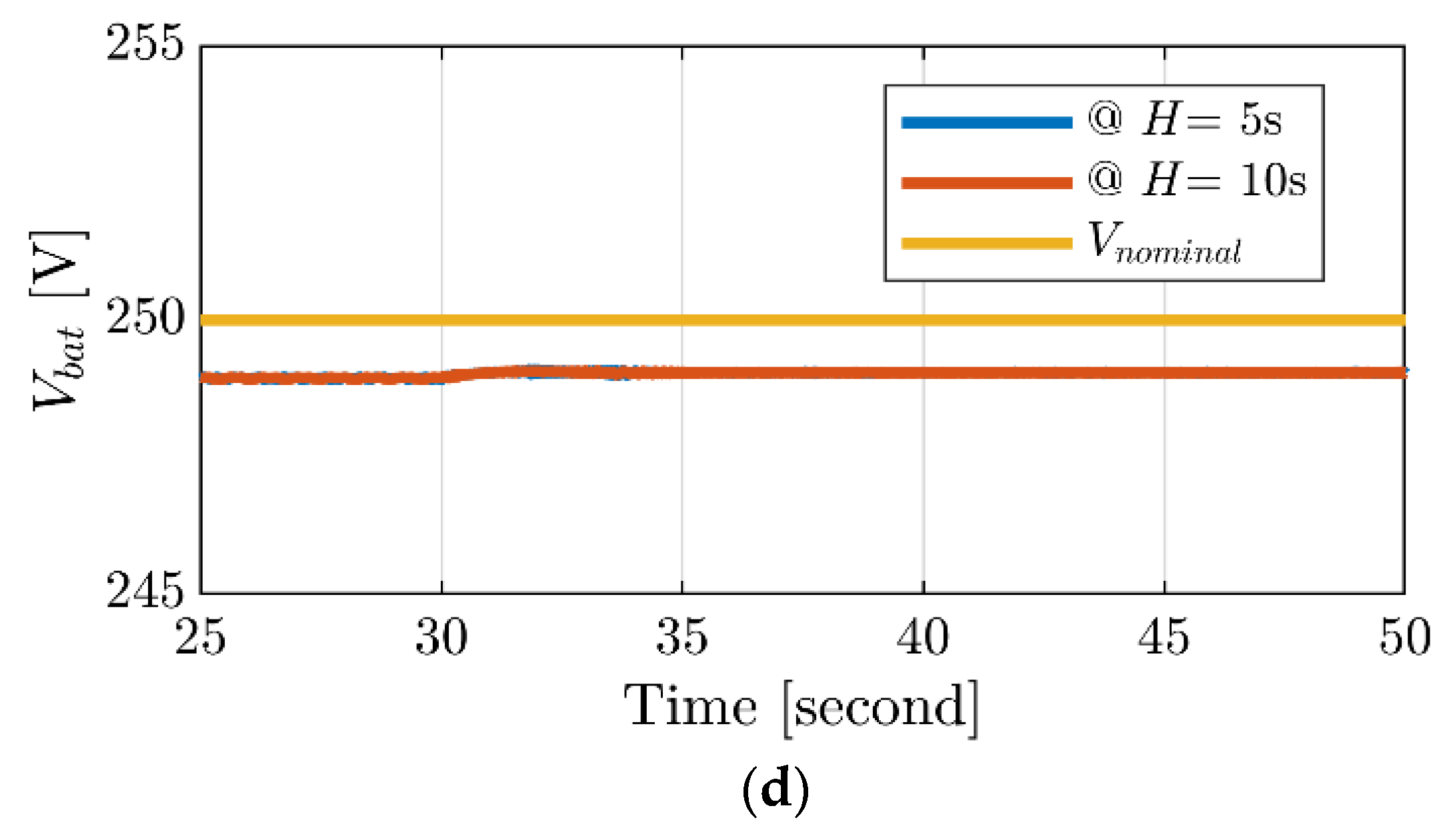
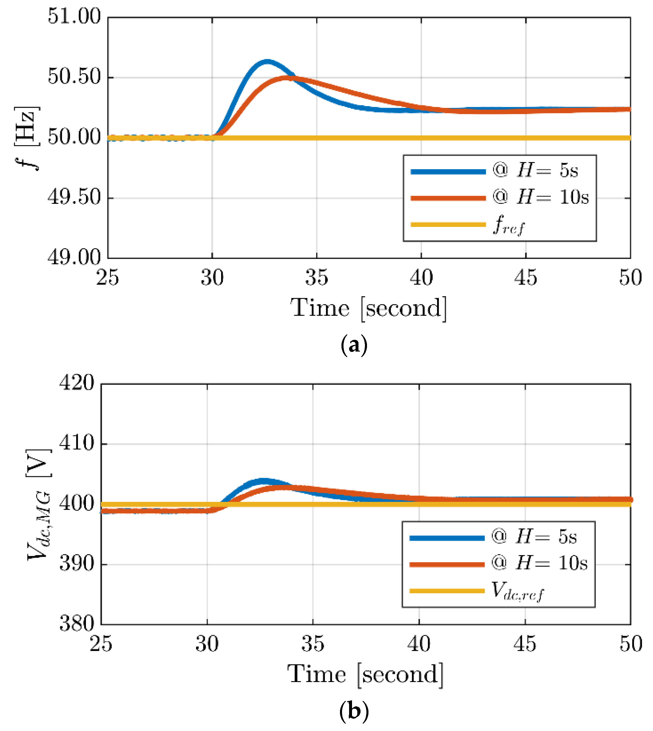
4.1. Case 1: Grid-Connected Mode

Simulations are carried out to assess the efficacy of the proposed control strategy by testing the system in grid-connected mode. The primary objective is to analyze the system’s performance and behavior during weak grid operation. In this scenario, the nominal values for the AC frequency and DC bus voltage in their corresponding subgrids are set at 50 Hz and 400 V, respectively.
As shown in Figure 9a, a step-down in the reference value of the active power Pac,ref from 1 kW to 0.8 kW (i.e., step-down by 20%), is implemented in the AC subgrid at the instance of 30 s. The proposed control system guarantees that the injected active power aligns with the reference for two different H constant values: H = 5 s and H = 10 s. The increased value of H helps to absorb energy more smoothly, which reduces the severity and impact of disturbances on the system (see Figure 9a). This implies that the system is designed to handle power fluctuations and disturbances more smoothly, minimizing their impact on the overall stability.
With respect to Figure 9b, which illustrates the behavior of DC power flow, a decrease in the DC power flow at t = 30 s can be noted by implementing the proposed method. This indicates that the power flowing through the bidirectional buck-boost converter decreases at t = 30 s due to the step-down of the Pac,ref mentioned earlier. The observed decrease in DC power flow could be attributed to the system’s response to a change in the reference signal, prompting an adjustment in power flow accordingly.
As shown in Figure 9c,d, the step-down in Pac,ref decreases the battery current (Ibat) because the proposed system is designed to support the AC subgrid by injecting the power from the BESS (see Figure 9c). Figure 9d shows that the voltage across the battery Vbat increased under the step-down in Pac,ref since the drawn battery current is decreased. Still, it is slightly lower than the nominal voltage Vnominal. The internal resistance of the battery typically causes slight deviations in battery voltage.
Figure 10a demonstrates the enhancement in the RoCoF of the system frequency when employing a high virtual inertia of 10 s for the converter. Meanwhile, Figure 10b shows the enhancement in the DC-link voltage at an inertia constant of 10 s in the DC microgrid.
The steady-state grid voltages and grid currents are depicted in Figure 11a,b when the proposed controller is active. It is evident from the waveforms that they exhibit pure sinusoidal characteristics that help maintain the desired power quality. This is attributed to the support provided by the VSM control, which is part of the proposed controller. By providing inertial support and regulating the power flow, the proposed control method enhances the stability and performance of the power grid without causing any adverse effects.

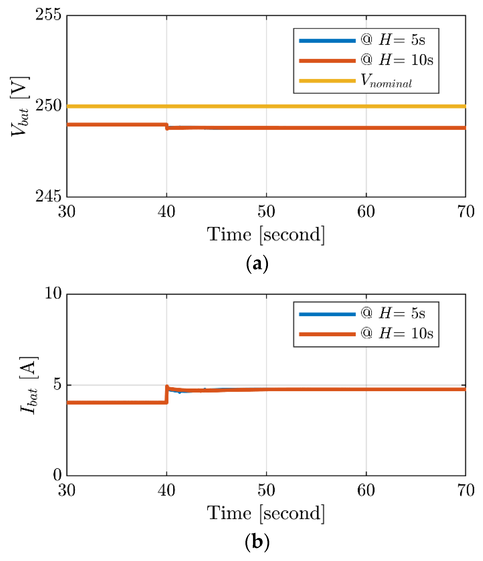
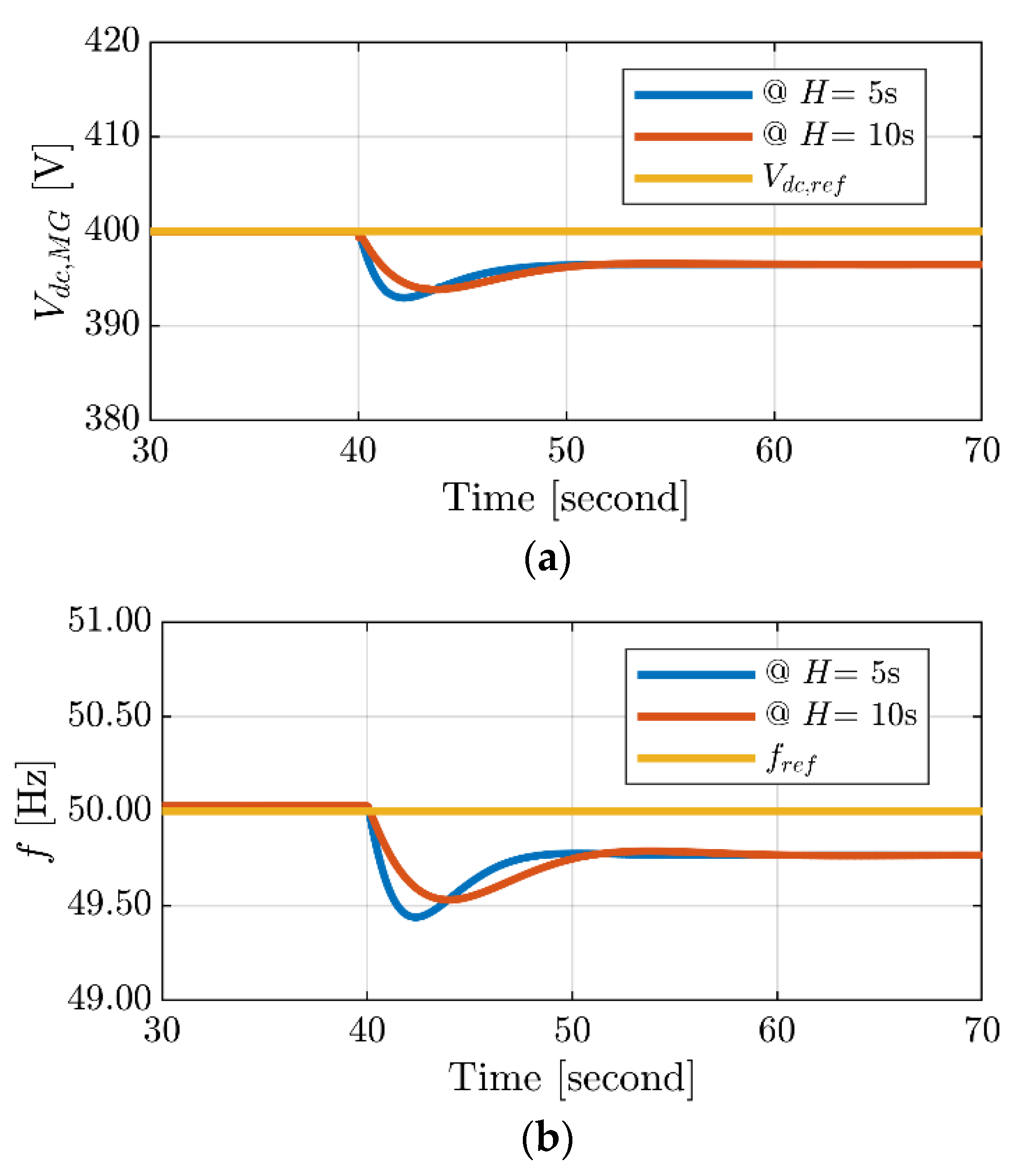
4.2. Case 2: Standalone Mode for Both Grid-Forming Converters

The AC and DC grids operate at their nominal power ratings, representing a 1 kW load in each subgrid. In Figure 12a, the simulation demonstrates an AC loading condition where the AC load increases from 1 kW to 1.2 kW. The DC loading remains constant at 1 kW. To maintain the nominal value of the DC bus voltage, the BIC transfers roughly 200 W of power from the DC subgrid to the AC subgrid, as shown in Figure 12b. The BIC manages the power transfer between the DC and AC subgrids in response to load change. When the AC load increases, the BIC transfers around 200 W from the DC subgrid to the AC subgrid. The simulations validate the effectiveness of bidirectional virtual inertia support in the standalone hybrid AC/DC microgrid.
The power transfer can indeed influence the voltage and current levels of the battery. As power is drawn from the battery to support the augmented AC load, the voltage level of the battery may decrease owing to the higher drawn current. At the instant t = 40 s, there is a noticeable decrease in the battery voltage level, as shown in Figure 13a. This indicates that the battery is supplying a significant amount of power to the AC subgrid. Simultaneously, there is an increase in the battery current, as depicted in Figure 13b, suggesting that the battery is discharging at a higher rate to maintain the desired power level. Figure 13a,b demonstrates how the BIC assists in maintaining stability between the AC and DC subgrids, adjusting their power flow based on load changes.
Figure 14a depicts the enhancement in the DC bus voltage, rising from 392 V to 394 V for the H values of 5s and 10s, respectively. This leads to a notable reduction in voltage deviation, exceeding 45%. Additionally, with the support of inertia from the DC side, the frequency nadir has improved from 49.40 Hz to 49.50 Hz, leading to a more than 25% frequency deviation reduction., as shown in Figure 14b.
As highlighted in Table 4, the proposed strategy showcases superior performance with minimal undershooting in both frequency and DC-link voltage. It surpasses the performance of [42], which consistently exhibits the lowest frequency deviation but the highest voltage deviation. This disparity can be attributed to the fact that the VSC in [42] focuses solely on regulating the inertial response of the AC side, leading to sacrificed frequency stability to maintain DC voltage stability. Conversely, [43] consistently showcases the smallest DC voltage deviation but the largest frequency deviation. The observed results highlighted in [43] lack of involvement in the inertial response resulted in a larger overshoot in the DC-link compared to [42] and a more significant overshoot in frequency relative to [43]. This emphasizes the trade-off between frequency and voltage stability inherent in the respective strategies.

5. Conclusions

This work proposes a new GF hybrid AC/DC MG strategy that utilizes bidirectional virtual inertia support. The strategy aims to enhance system stability and reliability by mitigating AC mains frequency and DC-link voltage deviations. Additionally, a control technique based on the VSM is introduced for the DC subgrid, contributing to overall stability and control. The VSM control actively adjusts the DC bus voltage in proportion to the system frequency, enabling the delivery of inertial power and improving grid stability.
The effectiveness of the proposed strategy has been confirmed through simulation results in both grid-connected and standalone modes. In grid-connected mode, it follows active power references, mitigating voltage and frequency fluctuations and enhancing power quality. Meanwhile, in standalone mode, the bidirectional virtual inertia support ensures stability between AC and DC subgrids, while the VSM control effectively regulates the DC bus voltage and enhances frequency control.
Overall, the proposed bidirectional virtual inertia support strategy, coupled with the VSM-based control for the DC MG, offers significant enhancements of stability and dynamic performance of hybrid AC/DC MGs. It addresses voltage and frequency fluctuations, improves power flow management, and enhances system resilience. These findings provide valuable insights for practical implementation in real-world MG systems, contributing to advancing sustainable and reliable power systems. Despite notable achievements, it is essential for future research to prioritize the integration of renewable resources and energy storage systems to enhance comprehensive grid resilience.

Author Contributions

Conceptualization, A.B.; methodology, A.B. and A.A.; software, A.B.; validation, A.B., A.C. and A.A.; formal analysis, A.B., A.C. and A.A.; investigation, A.B. and H.S.S.; resources, A.C. and S.A.Z.; data curation, A.A. and H.S.S.; writing—original draft preparation, A.B. and A.A.; writing—review and editing, A.C., S.A.Z., T.A.H.A. and H.S.S.; visualization, A.B. and A.A.; supervision, A.C. and S.A.Z.; project administration, S.A.Z. and T.A.H.A.; funding acquisition, T.A.H.A. All authors have read and agreed to the published version of the manuscript.

Funding

This research was supported in part by the Estonian Research Council grant PRG1086.

Data Availability Statement

The data presented in this study are available on request from the corresponding author.

Conflicts of Interest

The authors declare no conflict of interest.

Nomenclature

PrefActive power references (pu)
PinInput power (pu)
PmMechanical power (pu)
PLLoad power (pu)
ΔfFrequency deviation (Hz)
ΔPDAdditional active power (pu)
vg,abcIdeal voltage source (V)
VgdOutput voltage magnitude (V)
QrefReactive power references (pu)
wrefReference angular frequency (rad/sec)
δrefRotating angle (degree)
Vcd(t)d-axis components of converter voltage (V)
Vcq(t)q-axis components of converter voltage (V)
vgd(t)d- and components of grid voltage (V)
vgq(t)q-axis components of grid voltage (V)
icd(t)d-axis components of converter current (A)
icq(t)q-axis components of converter current (A)
woFundamental angular frequency (rad/sec)
SsvcAC subgrid switching signal
SbbcBIC switching signal
(∆f/fref)Relative frequency error
(∆VDC/Vdc,ref)Relative DC voltage error
VBES,refBattery voltage reference (V)
LbDC filter inductance (H)
CdcDC-link capacitance (F)
Vdc,refDC-link voltage reference (V)
Δvdc,maxMaximum DC-link voltage deviation (V)
LfAC filter inductance (H)
CfAC filter capacitance (F)
LgGrid inductance (H)
frefFrequency reference (Hz)
ΔfmaxMaximum frequency deviation (Hz)
Vg,refGrid RMS voltage (V)
PrefActive power reference (pu)
FswSwitching frequency (Hz)
RdroopFrequency/voltage droop coefficient
TgSpeed governor coefficient (s)
FHPTurbine HP coefficient
TRHReheater time constant (s)
TCHThe time constant of main inlet volumes (s)
HInertia coefficient (s)
DDamping coefficient
VNominalNominal voltage (V)
DERsDistributed energy resources
PVPhotovoltaic
WTsWind turbines
ESSsEnergy storage systems
MGMicrogrids
RESsRenewable energy sources
MPPTMaximum power point tracking
VSMsVirtual synchronous machines
BICsBidirectional interlinking converters
VISVirtual inertia support
PLLPhase-locked-loop
VSCVoltage source converter
GFGrid-forming
BESSBattery energy storage systems

References

  1. Sutherland, W.J.; Atkinson, P.W.; Butchart, S.H.M.; Capaja, M.; Dicks, L.V.; Fleishman, E.; Gaston, K.J.; Hails, R.S.; Hughes, A.C.; Le Anstey, B. A Horizon Scan of Global Biological Conservation Issues for 2022. Trends Ecol. Evol. 2022, 37, 95–104. [Google Scholar] [CrossRef] [PubMed]
  2. Al-Shetwi, A.Q.; Hannan, M.A.; Jern, K.P.; Mansur, M.; Mahlia, T.M.I. Grid-Connected Renewable Energy Sources: Review of the Recent Integration Requirements and Control Methods. J. Clean. Prod. 2020, 253, 119831. [Google Scholar] [CrossRef]
  3. Johnson, S.C.; Rhodes, J.D.; Webber, M.E. Understanding the Impact of Non-Synchronous Wind and Solar Generation on Grid Stability and Identifying Mitigation Pathways. Appl. Energy 2020, 262, 114492. [Google Scholar] [CrossRef]
  4. Bevrani, H.; Golpira, H.; Messina, A.R.; Hatziargyriou, N.; Milano, F.; Ise, T. Power System Frequency Control: An Updated Review of Current Solutions and New Challenges. Electr. Power Syst. Res. 2021, 194, 107114. [Google Scholar] [CrossRef]
  5. Fang, J.; Deng, H.; Tashakor, N.; Blaabjerg, F.; Goetz, S.M. State-Space Modeling and Control of Grid-Tied Power Converters with Capacitive/Battery Energy Storage and Grid-Supportive Services. IEEE J. Emerg. Sel. Top. Power Electron. 2021, 11, 234–250. [Google Scholar] [CrossRef]
  6. Zhang, H.; Xiang, W.; Lin, W.; Wen, J. Grid Forming Converters in Renewable Energy Sources Dominated Power Grid: Control Strategy, Stability, Application, and Challenges. J. Mod. Power Syst. Clean Energy 2021, 9, 1239–1256. [Google Scholar] [CrossRef]
  7. Zhang, Z.; Du, E.; Zhu, G.; Zhang, N.; Kang, C.; Qian, M.; Catalão, J.P.S. Modeling Frequency Response Dynamics in Power System Scheduling. Electr. Power Syst. Res. 2020, 189, 106549. [Google Scholar] [CrossRef]
  8. D’Arco, S.; Suul, J.A.; Fosso, O.B. A Virtual Synchronous Machine Implementation for Distributed Control of Power Converters in SmartGrids. Electr. Power Syst. Res. 2015, 122, 180–197. [Google Scholar] [CrossRef]
  9. D’Arco, S.; Suul, J.A. Equivalence of Virtual Synchronous Machines and Frequency-Droops for Converter-Based Microgrids. IEEE Trans. Smart Grid 2013, 5, 394–395. [Google Scholar] [CrossRef]
  10. Zaid, S.A.; Bakeer, A.; Magdy, G.; Albalawi, H.; Kassem, A.M.; El-Shimy, M.E.; AbdelMeguid, H.; Manqarah, B. A New Intelligent Fractional-Order Load Frequency Control for Interconnected Modern Power Systems with Virtual Inertia Control. Fractal Fract. 2023, 7, 62. [Google Scholar] [CrossRef]
  11. Chen, D.; Xu, Y.; Huang, A.Q. Integration of DC Microgrids as Virtual Synchronous Machines into the AC Grid. IEEE Trans. Ind. Electron. 2017, 64, 7455–7466. [Google Scholar] [CrossRef]
  12. Mo, O.; D’Arco, S.; Suul, J.A. Evaluation of Virtual Synchronous Machines with Dynamic or Quasi-Stationary Machine Models. IEEE Trans. Ind. Electron. 2016, 64, 5952–5962. [Google Scholar] [CrossRef]
  13. Malik, S.M.; Ai, X.; Sun, Y.; Chen, Z.; Zhou, S. Voltage and Frequency Control Strategies of Hybrid AC/DC Microgrid: A Review. IET Gener. Transm. Distrib. 2017, 11, 303–313. [Google Scholar] [CrossRef]
  14. Bakeer, A.; Elmorshedy, M.F.; Salama, H.S.; Elkadeem, M.R.; Almakhles, D.J.; Kotb, K.M. Optimal Design and Performance Analysis of Coastal Microgrid Using Different Optimization Algorithms. Electr. Eng. 2023, 105, 4499–4523. [Google Scholar] [CrossRef]
  15. Sahoo, S.K.; Sinha, A.K.; Kishore, N.K. Control Techniques in AC, DC, and Hybrid AC–DC Microgrid: A Review. IEEE J. Emerg. Sel. Top. Power Electron. 2017, 6, 738–759. [Google Scholar] [CrossRef]
  16. Bakeer, A.; Magdy, G.; Chub, A.; Jurado, F.; Rihan, M. Optimal Ultra-Local Model Control Integrated with Load Frequency Control of Renewable Energy Sources Based Microgrids. Energies 2022, 15, 9177. [Google Scholar] [CrossRef]
  17. Khodabakhsh, J.; Moschopoulos, G. Simplified Hybrid AC–DC Microgrid with a Novel Interlinking Converter. IEEE Trans. Ind. Appl. 2020, 56, 5023–5034. [Google Scholar] [CrossRef]
  18. Qu, Z.-W.; Chong, Z.-X.; Wang, Y.-J.; Shi, Z.; Yao, Y.-X. Control Method for Grid-Connected/Islanding Switching of Hybrid AC/DC Microgrid. J. Electr. Eng. Technol. 2023, 18, 15–25. [Google Scholar] [CrossRef]
  19. Ortiz, L.; Orizondo, R.; Águila, A.; González, J.W.; López, G.J.; Isaac, I. Hybrid AC/DC Microgrid Test System Simulation: Grid-Connected Mode. Heliyon 2019, 5, e02862. [Google Scholar] [CrossRef] [PubMed]
  20. Lin, P.; Wang, P.; Jin, C.; Xiao, J.; Li, X.; Guo, F.; Zhang, C. A Distributed Power Management Strategy for Multi-Paralleled Bidirectional Interlinking Converters in Hybrid AC/DC Microgrids. IEEE Trans. Smart Grid 2019, 10, 5696–5711. [Google Scholar] [CrossRef]
  21. Eisapour-Moarref, A.; Kalantar, M.; Esmaili, M. Power Sharing in Hybrid Microgrids with Multiple DC Subgrids. Int. J. Electr. Power Energy Syst. 2021, 128, 106716. [Google Scholar] [CrossRef]
  22. Zhang, Z.; Fang, J.; Dong, C.; Jin, C.; Tang, Y. Enhanced Grid Frequency and DC-Link Voltage Regulation in Hybrid AC/DC Microgrids through Bidirectional Virtual Inertia Support. IEEE Trans. Ind. Electron. 2022, 70, 6931–6940. [Google Scholar] [CrossRef]
  23. Khatibi, M.; Ahmed, S. Z-Source Virtual Synchronous Generator: Operation and Control. In Proceedings of the 2021 IEEE Applied Power Electronics Conference and Exposition (APEC), Phoenix, AZ, USA, 14–17 June 2021; pp. 97–104. [Google Scholar] [CrossRef]
  24. Ahmed, M.; Meegahapola, L.; Vahidnia, A.; Datta, M. Analysis and Mitigation of Low-frequency Oscillations in Hybrid AC/DC Microgrids with Dynamic Loads. IET Gener. Transm. Distrib. 2019, 13, 1477–1488. [Google Scholar] [CrossRef]
  25. Shafiee-Rad, M.; Sadabadi, M.S.; Shafiee, Q.; Jahed-Motlagh, M.R. Modeling and Robust Structural Control Design for Hybrid AC/DC Microgrids with General Topology. Int. J. Electr. Power Energy Syst. 2022, 139, 108012. [Google Scholar] [CrossRef]
  26. Tan, B.; Zhao, J.; Netto, M.; Krishnan, V.; Terzija, V.; Zhang, Y. Power System Inertia Estimation: Review of Methods and the Impacts of Converter-Interfaced Generations. Int. J. Electr. Power Energy Syst. 2022, 134, 107362. [Google Scholar] [CrossRef]
  27. Bakeer, M.; Magdy, G.; Bakeer, A.; Aly, M.M. Resilient Virtual Synchronous Generator Approach Using DC-Link Capacitor Energy for Frequency Support of Interconnected Renewable Power Systems. J. Energy Storage 2023, 65, 107230. [Google Scholar] [CrossRef]
  28. Niu, D.; Fang, J.; Yau, W.; Goetz, S.M. Comprehensive Evaluation of Energy Storage Systems for Inertia Emulation and Frequency Regulation Improvement. Energy Rep. 2023, 9, 2566–2576. [Google Scholar] [CrossRef]
  29. Fang, J.; Li, H.; Tang, Y.; Blaabjerg, F. On the Inertia of Future More-Electronics Power Systems. IEEE J. Emerg. Sel. Top. Power Electron. 2018, 7, 2130–2146. [Google Scholar] [CrossRef]
  30. Magdy, G.; Bakeer, A.; Nour, M.; Petlenkov, E. A New Virtual Synchronous Generator Design Based on the SMES System for Frequency Stability of Low-Inertia Power Grids. Energies 2020, 13, 5641. [Google Scholar] [CrossRef]
  31. Fang, J.; Li, H.; Tang, Y.; Blaabjerg, F. Distributed Power System Virtual Inertia Implemented by Grid-Connected Power Converters. IEEE Trans. Power Electron. 2017, 33, 8488–8499. [Google Scholar] [CrossRef]
  32. Fang, J.; Tang, Y.; Li, H.; Li, X. A Battery/Ultracapacitor Hybrid Energy Storage System for Implementing the Power Management of Virtual Synchronous Generators. IEEE Trans. Power Electron. 2017, 33, 2820–2824. [Google Scholar] [CrossRef]
  33. Salama, H.S.; Bakeer, A.; Magdy, G.; Vokony, I. Virtual Inertia Emulation through Virtual Synchronous Generator Based Superconducting Magnetic Energy Storage in Modern Power System. J. Energy Storage 2021, 44, 103466. [Google Scholar] [CrossRef]
  34. Long, B.; Liao, Y.; Chong, K.T.; Rodríguez, J.; Guerrero, J.M. MPC-Controlled Virtual Synchronous Generator to Enhance Frequency and Voltage Dynamic Performance in Islanded Microgrids. IEEE Trans. Smart Grid 2020, 12, 953–964. [Google Scholar] [CrossRef]
  35. Awais, M.; Khan, L.; Khan, S.G.; Awais, Q.; Jamil, M. Adaptive Neural Network Q-Learning-Based Full Recurrent Adaptive NeuroFuzzy Nonlinear Control Paradigms for Bidirectional-Interlinking Converter in a Grid-Connected Hybrid AC-DC Microgrid. Energies 2023, 16, 1902. [Google Scholar] [CrossRef]
  36. Etxegarai, A.; Eguia, P.; Torres, E.; Iturregi, A.; Valverde, V. Review of Grid Connection Requirements for Generation Assets in Weak Power Grids. Renew. Sustain. Energy Rev. 2015, 41, 1501–1514. [Google Scholar] [CrossRef]
  37. Fang, J.; Lin, P.; Li, H.; Yang, Y.; Tang, Y. An Improved Virtual Inertia Control for Three-Phase Voltage Source Converters Connected to a Weak Grid. IEEE Trans. Power Electron. 2018, 34, 8660–8670. [Google Scholar] [CrossRef]
  38. Maulik, S.; John, V. Synchronization Stability of 3-Phase Grid Connected Inverters in Weak Grids. In Proceedings of the IECON 2022—48th Annual Conference of the IEEE Industrial Electronics Society, Brussels, Belgium, 17–20 October 2022; pp. 1–6. [Google Scholar]
  39. Fang, J.; Yu, J.; Zhang, Y.; Goetz, S.M. An Estimation-Based Solution to Weak-Grid-Induced Small-Signal Stability Problems of Power Converters. IEEE J. Emerg. Sel. Top. Power Electron. 2020, 9, 4558–4572. [Google Scholar] [CrossRef]
  40. Padiyar, K.R. Analysis of Subsynchronous Resonance in Power Systems; Springer Science & Business Media: Berlin, Germany, 1999; Volume 471, ISBN 0792383192. [Google Scholar]
  41. da Silva, C.H.; Pereira, R.R.; da Silva, L.E.B.; Lambert-Torres, G.; Bose, B.K.; Ahn, S.U. A Digital PLL Scheme for Three-Phase System Using Modified Synchronous Reference Frame. IEEE Trans. Ind. Electron. 2010, 57, 3814–3821. [Google Scholar] [CrossRef]
  42. Wang, J.; Huang, W.; Tai, N.; Yu, M.; Li, R.; Zhang, Y. A Bidirectional Virtual Inertia Control Strategy for the Interconnected Converter of Standalone AC/DC Hybrid Microgrids. IEEE Trans. Power Syst. 2023, 39, 745–754. [Google Scholar] [CrossRef]
  43. Fathi, A.; Shafiee, Q.; Bevrani, H. Robust Frequency Control of Microgrids Using an Extended Virtual Synchronous Generator. IEEE Trans. Power Syst. 2018, 33, 6289–6297. [Google Scholar] [CrossRef]
Figure 1. Configuration of the hybrid AC/DC MG.
Processes 12 00139 g001
Figure 2. The framework for regulating the frequency and DC-link voltage via inertia control.
Processes 12 00139 g002
Figure 3. Configuration of the case-study GF converter for hybrid AC/DC microgrids.
Processes 12 00139 g003
Figure 4. Control diagram for (a) Q–Vgd,ref and (b) P-δ droop.
Processes 12 00139 g004
Figure 5. PQ measurements in normalized units.
Processes 12 00139 g005
Figure 6. The voltage/current regulation in the synchronous reference frame.
Processes 12 00139 g006
Figure 7. Proposed control of the DC MG based on the VSM technique.
Processes 12 00139 g007
Figure 8. Configurations of the proposed frequency control approach.
Processes 12 00139 g008
Figure 9. Simulation results for the grid-connected mode during step-down in reference value of the AC power: (a) active power for AC MG, (b) DC output power for DC MG, (c) output battery current, and (d) the battery voltage.
Processes 12 00139 g009aProcesses 12 00139 g009b
Figure 10. Simulation results for the grid-connected mode: (a) frequency and (b) DC-link voltage.
Processes 12 00139 g010
Figure 11. Simulation results for the grid-connected mode: (a) grid current and (b) grid voltage.
Processes 12 00139 g011
Figure 12. Simulation results for the standalone mode: (a) active power in the AC subgrid and (b) the DC output power in the DC subgrid.
Processes 12 00139 g012aProcesses 12 00139 g012b
Figure 13. Simulation results for the standalone mode: (a) battery voltage and (b) battery current.
Processes 12 00139 g013
Figure 14. Simulation results for the standalone mode: (a) DC bus responses of the DC subgrid and (b) frequency response of the AC subgrid.
Processes 12 00139 g014
Table 1. Summary of the existing work.
RefsRESsESSsMain Concept of VSG MethodologyMain ControllerContributions
[22]Not definedBattery storageThe concept of virtual inertia for a bidirectional interlinking converter.Droop control.-The transient performance of frequency is enhanced when the rate-of-change-of-frequency (RoCoF) is reduced.
-It is capable of offering inertia support and voltage regulation.
[30]Wind and PVBattery storageThe control strategy is dependent on the virtual controller.PI controller.Mitigating the changes in system frequency during various disturbances.
[32]Not definedBattery and an ultracapacitorIntroduces a hybrid energy storage system that combines batteries and ultracapacitors for efficient power management (VSGs).Droop control.-Decreases the release duration of stored energy
-Mitigates the impact of high-frequency
-Achieves power regulation of VSGs.
[33]PVSuperconducting magnetic energy storageVSG combined with superconducting magnetic energy storage (SMES).PI controller and decoupled controller.-The load changes can be mitigated and enhanced by suppressing and improving the frequency and voltage fluctuations.
-Enhance the degree of variation in frequency.
[34]Not definedEnergy storage systemA mathematical model of VSG is developed to forecast the best output power of VSG, hence improving the frequency dynamics of the system.The three-step prediction MPC-VSG control method.The proposed method can increase the dynamic features of system voltage and frequency by providing inertia support during transient situations.
[35]Wind and PVBattery storageThe advantages of Q-learning and full recurrent neuro-fuzzy are merged.Model-free control strategy.The optimization of active-reactive power flow, regulation of voltage, frequency, and reduction of THD.
Table 2. System parameters used in the simulation study.
DescriptionSymbolValue
Battery voltage referenceVBES,ref250 V
DC filter inductanceLb5.6 mH
DC-link capacitanceCdc3.76 mF
DC-link voltage referenceVdc,ref400 V
Maximum DC-link voltage deviationΔvdc,max27
AC filter inductanceLf10 mH
AC filter capacitanceCf100 µF
Grid inductanceLg1 mH
Frequency referencefref50 Hz
Maximum frequency deviationΔfmax0.2 Hz
Grid RMS voltageVg,ref110 V
Active power referencePref1 kW
Switching frequencyFsw10 kHz
Table 3. Parameters of the proposed GF control strategy.
DescriptionSymbolValue
Frequency/voltage droop coefficientRdroop0.05
Speed governor coefficientTg0.1 s
Turbine HP coefficientFHP0.3 s
Reheater time constantTRH7 s
The time constant of main inlet volumesTCH0.2 s
Base inertia coefficientH5 s
Base load damping coefficientD1
Per unit reference valuesP/Q/V/f1
Table 4. Numerical analysis of the proposed controller.
Strategy[22][42][43]Proposed Strategy
DC-link voltage deviation/V5.557.503.904.00
Frequency deviation/Hz0.320.230.320.30
Disclaimer/Publisher’s Note: The statements, opinions and data contained in all publications are solely those of the individual author(s) and contributor(s) and not of MDPI and/or the editor(s). MDPI and/or the editor(s) disclaim responsibility for any injury to people or property resulting from any ideas, methods, instructions or products referred to in the content.

