Abstract
Drill bits are the main rock-breaking tools in the petroleum and gas industry. Their performance directly affects the quality, efficiency, and cost of drilling. Drill bit manufacturing mainly employs traditional mold forming processes such as milling molding and press molding, which have low production efficiency and long processing cycles and are not conducive to rapid responses to field requirements. Inadequate production accuracy makes it difficult to produce drill bits with complex structures. Three-dimensional (3D) printing technology has fast molding speeds and high molding accuracy. In this paper, 3D printing was applied for the first time to the manufacture of molds for carcass polycrystalline diamond compact (PDC) drill bits and PDC–cone hybrid drill bits. In comparison with forging and milling molding, 3D printing improved production efficiency. The manufactured molds had higher machining accuracy. The ability of 3D printing to make molds with complex surfaces enables the development of drill bits with complex structures. A field experiment was conducted on a PDC drill bit produced by 3D printing, which had a higher rate of penetration and was more efficient in breaking rocks than bits manufactured by traditional processes. The ROP of the drill bit increased by 20.1–25.8%, and the drilling depth increased by 7.7–29.5%. It is therefore feasible to apply 3D printing to the manufacture of petroleum drill bits.
1. Introduction
At present, the main types of drill bits commonly used in the petroleum industry include roller cone bits, polycrystalline diamond compact (PDC) bits, and mixed cone–PDC bits. The manufacture of the body of a drill bit mainly employs traditional molding processes such as milling molding and press molding, which have long processing cycles and low processing accuracy and are not conducive to rapid responses of the design of individual drill bits to complex strata.
Three-dimensional (3D) printing technology is a cumulative manufacturing technology, which is a kind of rapid prototyping technology. Based on the digital model file, the three-dimensional model designed in the computer is layered to obtain many two-dimensional plane graphics, and then the adhesive powder materials of various materials are printed layer by layer to stack these two-dimensional graphics into three-dimensional entities, including the modeling of three-dimensional models, machinery and its automatic control (mechatronics), model layering and conversion into printing instruction code software (stratasys Design Series objet30), and other technologies [1,2,3]. With the maturity of 3D printing technology, it has been widely used in vehicles and aviation and is rapidly expanding into various other fields.
At present, there are many studies on the processing method of PDC bits using 3D printing technology, which is limited to the processing of bit models, and there are few studies on actual bit manufacturing and field experiments, especially the application of cone–PDC hybrid bits. In this paper, 3D printing technology is introduced into the manufacturing process of PDC bit and cone–PDC hybrid bit dies, the manufacturing accuracy of 3D printing and traditional processing technology is compared and analyzed, and the field application comparison test of the PDC bit is completed, providing data support for the integration of 3D printing technology into the manufacturing process of petroleum bits [4,5,6].
The main contribution is the use of 3D printing technology to manufacture PDC drill bits, which reduces manufacturing time and improves manufacturing accuracy. Through on-site experiments, it is verified that 3D printing technology is suitable for oil and gas drill bits, improving their rock-breaking efficiency and service life.
The research idea of the manuscript is to first introduce the principles and advantages of 3D technology, then use 3D technology to manufacture molds for PDC drill bits and PDC composite drill bits, relying on 3D coordinate instruments to detect the machining accuracy of 3D-printed molds, pressure molds, and milling molds by using traditional processes. Finally, two different types of PDC bit products were manufactured using 3D printing technology, and field experiments were completed, which verified the feasibility of 3D manufacturing technology in oil bit manufacturing and provided ideas and data support for the future application of 3D printing technology for conical PDC composite bits. The research roadmap for the manuscript is shown in Figure 1.
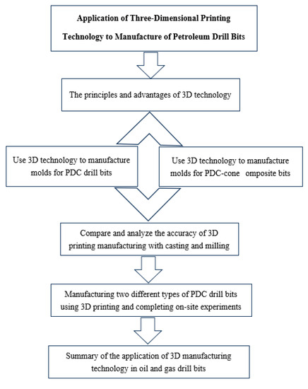
Figure 1.
Research roadmap for the manuscript.
2. The Principles and Advantages of 3D Printing
2.1. The Principles of 3D Printing Technology
With the development of computer technology, the basic principle of 3D printing is first to design the 3D digital model of the object to be printed using the computer, and then use the layer-by-layer method to form the parts. It is suitable for personalized structures, small batches, complex shapes, hollow parts, and other components. This technology can produce a prototype directly from a computer-aided design (CAD) to a 3D solid model within a few hours or more. In comparison with the information provided by drawings and computer screens, rapid prototyping provides richer and more intuitive representations. At present, 3D printing technology mainly includes three different printing methods: laser sintering, light curing, and melt deposition modeling. The 3D printing method used in this paper is the stereolithography apparatus (SLA), which gradually solidifies and forms the light-curing material by irradiating the surface of the material with a specific wavelength and intensity. Its working principle is shown in Figure 2 [7,8]. Due to the advantages of fast forming, great versatility, high processing accuracy, and high cost–performance ratio, the SLA is very suitable for the manufacturing of different molds and models of drill bits [9,10,11].
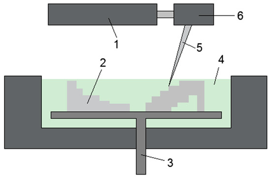
Figure 2.
Working principle of the stereolithography apparatus: (1) laser; (2) cured resin layer; (3) lifting platform; (4) liquid resin; (5) laser beam; (6) scanning system.
2.2. Advantages of 3D Printing Technology
In comparison with traditional processing methods, 3D printing has the following advantages in the manufacture of oil drill bits:
- (1)
- Short processing cycles. Three-dimensional printing is directly driven by CAD model printing equipment for processing and can quickly complete 3D solid parts with arbitrary complex shapes. Especially in the product development stage, the use of rapid prototyping makes it possible to consider various factors and develop a successful product at the first attempt, so as to shorten the development cycle, improve product quality, reduce costs, and avoid investment risk [12,13,14].
- (2)
- High precision of machining. The precision of machining in 3D printing is associated with the particle size and layer thickness of the materials. At present, the particle sizes of printed materials are able to fully meet the precision requirements of drill bit molds. As long as the layer thickness is reduced in the process of machining, it can meet accuracy requirements, and at present most manufacturers have industrial equipment that can reach an accuracy of ±0.01 mm [15,16,17,18].
- (3)
- Three-dimensional printed products can meet the basic requirements of drill bit molds. At present, 3D printing usually uses the laser irradiation sintering of resins, nylon, and other materials, which can meet the requirements for stability and strength of basic molds [19,20].
- (4)
- The non-contact processing method has no residual stress problems of traditional processing, no problems such as tool replacement and wear, no cutting, noise, vibration, etc., which is conducive to environmental protection.
3. Application of 3D Printing Technology to PDC Bit Manufacturing
The PDC bit is a cutting-type bit formed by welding or inlaying an artificial polycrystalline diamond composite sheet in the bit and has a fixed cutting structure. Among the many mechanical strengths of rocks, the lowest is the tensile strength, followed by the shear strength, while the compressive strength is the highest; the compressive strength is several times higher than the shear strength, so it has long been recognized that this method of cutting rocks is the most effective. PDC bits just use PDC teeth to scrape or shear the rock in order to break it.
The PDC bit is composed of a bit body, cutting structure, and hydraulic structure, and the manufacturing process is complex. Mold forming (as shown in Figure 3) is an important stage in the manufacture of carcass PDC bits and is also the key to accurately implementing the design of a bit. The precision and quality of mold forming directly affect the performance of a PDC bit. Traditional processing is mainly carried out by two methods: milling molding and press molding. Milling molding is performed, according to the design, by using a milling machine equipped with a tooling fixture to machine the angle and depth of the cutting teeth of the drill at the designed position in a graphite cavity in a produced outline of the drill and manually placing a sink block to form a sintering mold for the PDC drill. Press molding is, according to the design, performed by processing a master mold using a computer numerical control (CNC) machine tool. The general master mold of the drill is processed in a three-axis CNC machine tool equipped with fixtures and jigs, and the process is supplemented by manual repair [21,22].
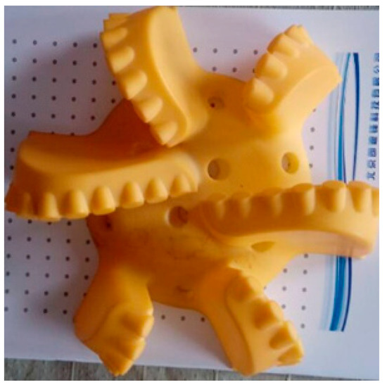
Figure 3.
Mold of a carcass polycrystalline diamond compact (PDC) bit.
Traditional processes for drill bit mold forming such as milling mold forming and press mold forming have low molding accuracy, low production efficiency, and long product development cycles, which are not conducive to rapid responses to field requirements. The production of drill bits with complex structures is even more difficult to achieve. In response to various problems in the manufacture of traditional carcass PDC drill bits, this paper introduces 3D printing into the manufacture of carcass PDC bits, and this new mold-forming process is available to solve the above problems.
The complicated spatial structure of a PDC bit, especially the angle and exposed height of the cutting teeth, makes it difficult to machine. The new process combines computer technology, laser technology, numerical control, plastic molding techniques, and clay powder molding techniques to form the complex shape of a fine PDC bit by sintering and abrasive processing. The manufacturing parameters of the 3D printing model are as follows: the material is polymer polycarbonate, the layer thickness is 0.3 mm, the exposure time is 6 s, the lifting speed is 65 mm/min, the anti-aliasing function is selected as level 4, the printing temperature is 200–210 °C, the filling method considers structural support, and the filling ratio is 20%.
The traditional drill die manufacturing process includes 12 processes such as turning the graphite die, marking the graphite die, and milling the teeth of the graphite die, while the 3D printing drill die manufacturing process reduces the process to 6 processes. The manufacturing process is greatly simplified, while greatly reducing the labor intensity of workers and minimizing human error.
It can be seen from Table 1 that the precision of molds processed by 3D printing is greatly improved. Three-dimensional printing can be used to produce arbitrary complex curved surfaces of molds. This technology is integrated into the manufacture of drill molds with existing soft mold forming processes to process drill base molds for drill manufacturing, which improves traditional mold processing methods and thus realizes the efficient development of PDC bits with complex structures and tip shapes.

Table 1.
Machining errors of three processing techniques.
In comparison with traditional processes for bit mold forming, the new process has the following advantages: (1) Three-dimensional printing simplifies the machining process and can be directly driven by CAD model printing equipment without milling operations, which reduces the labor involved and improves efficiency. It can also be applied to drill bits with complex structures without the need for part programming, and there are no specific skill requirements for technical personnel, which thus shortens the development cycle of new products and improves manufacturing efficiency. (2) Test data have proved that basic molds produced by 3D printing can meet the requirements of drill bit design in terms of accuracy, strength, and surface finish, and the precision is higher than that of molds processed by ordinary techniques. Compared with existing machining processes, the manufacturing accuracy of drill bits has been improved by 5–8 times.
4. Application of 3D Printing Technology to PDC–Cone Hybrid Bits
PDC bits mainly break rocks by scraping or shearing action. When drilling an abrasive hard formation, the PDC teeth continuously cut rocks, and the heat generated by intense friction will make PDC teeth reach a very high temperature. When the temperature exceeds a certain limit, the wear speed of PDC teeth increases significantly, resulting in the thermal wear phenomenon. The failure of individual teeth on the bit (tooth loss, fracture or excessive wear, etc.) will significantly increase the working load of teeth near the bottom of the hole band of the failed tooth, accelerate its wear rate, and lead to premature failure of the bit [23,24,25,26]. Tricone bits break the rock mainly by means of crushing (crushing the rock by pressing teeth into it). The impact of the teeth is very large, the force is extremely complex, and the harsh working conditions result in the teeth pressed into the tooth wheel hole being subject to breaking, falling, and other hidden dangers. The cones of the tricone are assembled in a limited space, and the size is limited. In order to ensure strength, the bearing in the cone cannot be too small, the teeth are large, and the interference is pressed into the cone, so the cone of the tricone may be excessively worn or the shell breaks and falls to the bottom of the well [27,28,29,30].
A PDC–cone hybrid bit (as shown in Figure 4) has two rock-breaking mechanisms, namely, continuous shear and cone crushing. The PDC bit cuts through rock continuously at the bottom of the well, where the PDC cutter penetrates into the formation under the effect of the bit pressure while it is still rotating. In this way, the PDC cutter breaks rock as it penetrates and cuts at the same time. Under the effect of the bit pressure, when the teeth in the same ring alternate with the adjacent teeth, the teeth strike the formation and form several rings of discontinuous concentric crushing pits at the bottom of the well. The crushing pits produced by the teeth can interrupt the continuous scraping action of PDC cutters, which causes overheating of the cutters, and thus mitigate thermal wear on the cutters and contribute to prolonging the lifespan of the cutters. They can also help the PDC bit to penetrate into the formation to achieve the shearing of the rock, which is a highly efficient rock-breaking mechanism in comparison with grinding [31,32].
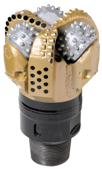
Figure 4.
A 3 + 3 PDC–cone hybrid bit.
Individual PDC bits and roller cone bits are well developed already. Here, the processing of PDC–cone hybrid bit assemblies is mainly considered. Processing errors, assembly errors, and welding deformation of drill parts affect the accuracy of the drill diameter and the matching of the cone and fixed blades. Three-dimensional printing is applied to the manufacture of composite drill bits (as shown in Figure 5).
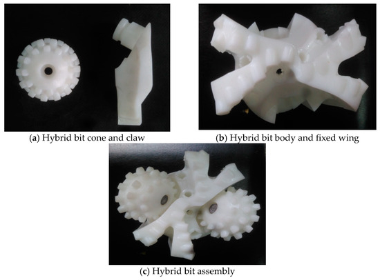
Figure 5.
Three-dimensional printing technology applied to hybrid bits.
The alloy steel (20CrMo or 15MnNi4Mo) in a hybrid bit is made by die forging, by which it is easy to tilt the end face of the cone and the claw toward the axis, but it is not conducive to the assembly of the cone and the claw. Sharp edges and burrs in the corner area need to be polished because the material, temperature, processing technique, and other factors can easily cause forging cracks in the cone. Drilling for machining positioning is needed on the conical surface of the cone, and machining marks are more serious at the bottom of a perforation, where large machining burrs may form the sources of cracks. The larger the interference due to a perforation, the greater the stress on the perforation. The taper of a perforation increases the stress at the bottom of the perforation, and a small distance to the bottom of a perforation also reduces the anti-crack ability of the bottom of the perforation. The fixed blades and body of a composite bit are usually completed on a five-axis interactive machining center.
A hand-held laser scanner was used to scan the composite bit (as shown in Figure 6a), and the generated 3D graph (as shown in Figure 6b) was compared with the 3D printed model. The machining error is shown in Table 2.
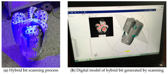
Figure 6.
Three-dimensional laser scanning applied to a hybrid bit.
Table 2.
Machining errors of different processes.
It can be seen from Table 2 that the accuracy of the cone and tooth claw processed by 3D printing was greatly improved in comparison with forging molding. In addition, the precision of 3D printing was on the same order of magnitude as that of the drill body and fixed wing processed by the five-axis CNC center. The application of this technology to the manufacture of hybrid bits can realize the efficient research and development of composite bits while ensuring accuracy.
5. Field Application of PDC Bits
5.1. Application of 3D-Printed PDC Drill Bits in Soft Formations
According to the requirements of the stratigraphic conditions and the drilling process used in the Zu203H3-4 well, one PDC bit with a diameter of 215.9 mm was designed. The bit included two main cutter wings and three secondary cutter wings; the crown height of the bit was 30 mm; the crown top radius was 50 mm; the crown height category was medium; the inner cone depth was 3.5 mm; the inner cone angle was 15°; the inner cone shape category was shallow; the PDC tooth diameter was 15.875 mm; the total number of main cutting teeth was 24; the blade was linear; the total flow area was 14.8 cm2; the chip flute area was 276.5 cm2; and the average runner depth was 43 mm. The model WS505HK drill bit was manufactured by processing a 3D-printed rubber mold, and the product is shown in Figure 7.
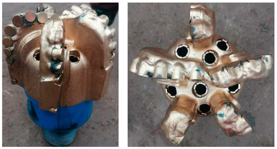
Figure 7.
WS505HK PDC drill bit.
The drilling tool combination was as follows: 215.9 mm PDC bit + 194 mm twist punch + 172 mm screw + floating valve + 158.8 mm drill tappet 1 + 215 mm holdup + 158.8 mm drill tappet 2 + 158.8 mm shocker + 158.8 mm drill tappet 3 + 127 mm drill string.
A new WS505HK drill bit was manufactured and employed in the 203H3-4 well. The drill bit diameter was 215.9 mm, and the nozzle type was 7 × Φ20#. When the bit touched the bottom of the well, the rotational speed was 25 r/min, and the drilling pressure was 60–70 KN. The cement casing at the bottom of the well was swept for about 20 m. At this time, the drilling time was 7–8 min/m. When the bit finished drilling the cement casing into the formation, the drilling time was kept at 1–2 min/m. The formation was the Penglaizhen Formation, and the lithology was purple-red mudstone and siltstone. Drilling was started at 1905.16 m, and the reason for starting drilling was screw tool failure.
After starting drilling with the bit, as shown in Figure 8, there was no wear on the drill bit; the cutting teeth on the inner cone were intact; there was no wear on the diameter-keeping teeth; and the drill bit could go down the well for a second time.
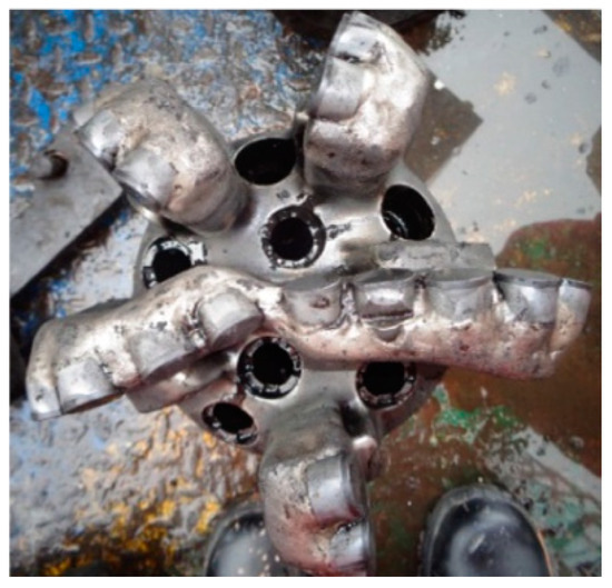
Figure 8.
PDC bit after starting drilling.
From the comparisons of the use of the PDC bit shown in Table 3 and Figure 9, it can be seen that the rate of penetration (ROP) of the new WS505HK PDC bit was at least 14.7% higher than those of bits in the same layer in offset wells. In comparison with the offset wells, the average ROP in the same formation increased by 25.8%. The drilling length was also greater than that of bits in the same layer in offset wells, with a minimum improvement of 3.8% over the same layer in an offset well and an average improvement of 7.7%. The new bit further improved the efficiency of rock breaking in comparison with conventional bits.
Table 3.
WS505HK Comparison of drill applications.
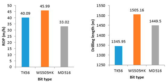
Figure 9.
Comparison of the effect of using the WJ505HK PDC drill bit.
5.2. Application of 3D Printed PDC Drill Bits in Hard Formations
According to the geological conditions and drilling process requirements of the 6-inch wellbore of Well 203H3-4, a 152.4 mm diameter PDC drill bit was designed, which adopts a double row tooth design of three main blades and two auxiliary blades. The crown height of the drill bit is 25 mm; the crown radius is 35 mm; the crown height category is medium; the inner cone depth is 2 mm; the inner cone angle is 18°; the inner cone shape category is medium; the PDC teeth have a diameter of 13.44 mm; the number of main cutting teeth is 20 in total; the blade shape is straight; the TFA is 1.8 in 2; the area of chip removal groove is 35.45 cm2; and the average channel depth is 32 mm. The drill bit model WS503HK is manufactured through 3D-printed rubber mold processing, and the product is shown in Figure 10.
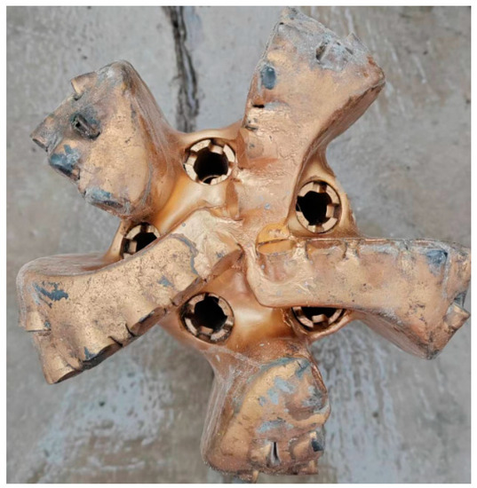
Figure 10.
WS503HK PDC drill bit.
Drilling tool assembly: 152.4 mm PDC drill bit + 120 mm motor ++ float valve + 120 mm drill stem 1 piece + 120 mm centralizer + 120 mm drill stem 22 pieces + 120 mm jar + 120 mm drill stem 3 pieces + 120 mm drill stem string.
The drill bit WS503HK entered well 203H3-4 with nozzle: 5 × Φ22#. When the drill bit contacted the bottom of the well, the rotational speed was 30 r/min, the drilling pressure was 30–50 KN, and the cement slurry at the bottom of the well was cleared for about 20 m. At this time, the drilling time was 7–8 min/m. When the drill bit completed drilling the cement slurry into the formation, the drilling time was maintained at 15–30 min/m. The layer was an Archaean buried hill, and the lithology was granite. When drilling reached 3300.53 m, the drill bit was pulled out. The reason for pulling out was the completion of drilling.
The drill bit after being pulled out is shown in Figure 11. The wear condition of the drill bit was as follows: the inner cone cutting teeth of the drill bit were intact, the outer cone cutting teeth had 2–3 mm wear, and the diameter retaining teeth were not worn. The novelty of the drill bit reaches 80%, and it could be lowered into the well again.
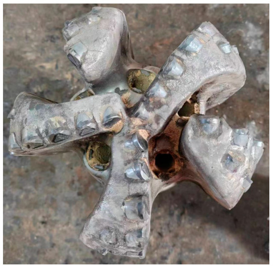
Figure 11.
WS503HKPDC drill bit after drilling out.
From the comparison of PDC bit usage in Table 4 and Figure 12, it can be seen that the mechanical penetration rate of the WS503HK new PDC bit is at least 15.2% higher than that of adjacent wells in the same layer. Compared to adjacent wells, the average mechanical drilling speed in the same layer increased by 20.1%. The new drill bit footage is also at least 19.7% higher than that of adjacent wells in the same layer, and the average footage is 29.5% higher than that of adjacent wells in the same layer. The new drill bit thus further improved its rock-breaking efficiency compared to traditional drill bits.
Table 4.
WS503HK Comparison of drill applications.
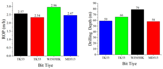
Figure 12.
Comparison of the effect of using the WJ503HK PDC drill bit.
6. Conclusions
The new process devised by applying 3D printing to the forming of drill bit molds has the following advantages: (1) The manufacturing cycle of drill bits will be greatly shortened and can be adapted to the complex and changeable demands of the market. The manufacturing cycle of drill bits was shortened to 3–5 days. (2) With higher machining accuracy, compared with existing machining processes, the manufacturing accuracy of drill bits was improved by 5–8 times. It will be possible to realize the manufacture of PDC bits with complex structures such as spiral flutes and shockproof teeth. (3) In a field application experiment on a PDC bit, it was also found that the new bit has higher rock-breaking efficiency. The ROP of the drill bit increased by 20.1–25.8%, and the drilling depth increased by 7.7–29.5%.
In this paper, 3D printing of dies for PDC bits and PDC–roller cone hybrid bits was carried out and compared with conventional processes in terms of the machining process and precision. A field experiment was also conducted on a new PDC bit, and desirable data were obtained. If more research and innovation can be carried out on the materials and process, this new technology will be widely used in the manufacture of oil drill bits, with great application value and broad market prospects. Three-dimensional printing manufacturing technology is only applied to PDC drill bits. In the future, metal 3D manufacturing technology will be applied to cone–PDC composite drill bits to improve the manufacturing efficiency and accuracy of composite drill bits.
Author Contributions
Conceptualization, B.L. and Y.W.; methodology, J.J.; software, B.Z.; validation, J.Z., K.H. and B.L.; formal analysis, Y.W.; investigation, J.J.; resources, B.Z.; data curation, J.Z.; writing—original draft preparation, K.H.; writing—review and editing, B.L.; visualization, Y.W.; supervision, J.J.; project administration, B.L. and K.H.; funding acquisition, K.H. All authors have read and agreed to the published version of the manuscript.
Funding
This research was funded by the Industry Technology Research Institute of Intelligent Manufacturing, Sichuan University of Arts and Science (fund number: ZNZZ2217), the open fund project of the State Key Laboratory of Oil and Gas Reservoir Geology and Exploitation (Southwest Petroleum University) in 2022 (grant no. PLN2022-29), and the Natural Science Foundation of Sichuan Province (2022NSFSC0265).
Data Availability Statement
Data available on request due to restrictions e.g., privacy or ethical. The data presented in this study are available on request from the corresponding author. The data are not publicly available due to [Signed a technical confidentiality agreement with the enterprise].
Acknowledgments
The authors disclose the receipt of the following financial support for the research, authorship, and/or publication of this article: this work was supported by the Industry Technology Research Institute of Intelligent Manufacturing, Sichuan University of Arts and Science (fund number: ZNZZ2217), the open fund project of the State Key Laboratory of Oil and Gas Reservoir Geology and Exploitation (Southwest Petroleum University) in 2022 (grant no. PLN2022-29), and the Natural Science Foundation of Sichuan Province (2022NSFSC0265).
Conflicts of Interest
The authors declare that there are no conflict of interest regarding the publication of this paper.
References
- Zhang, X.J.; Tang, S.Y.; Zhao, H.Y.; Guo, S.Q.; Li, N.; Sun, B.B.; Chen, B.Q. Research status and key technologies of 3D printing technology. Mater. Eng. 2016, 44, 122–128. [Google Scholar]
- Zhang, S.; Xu, Y.; Sun, S. Research and development of 3D printing materials. Chin. Plast. 2016, 30, 7–14. [Google Scholar]
- Huang, D.; Li, J.; Lv, H.; Zhang, H. Research progress of bio-3d-printed stem cells. Chin. J. Clin. Anat. 2019, 37, 603–607. [Google Scholar]
- Lee, K.; Yoann, D.E.; Ranchert, D.E.; Mim, G.J. Progress in 3D printing technology and application of soft materials. Plastics 2019, 48, 101–106. [Google Scholar]
- Zhang, J.; Zhang, J.; Zhao, J.; Shen, Y.; Hua, G.; Huang, Y. Application research progress of laser rapid prototyping technology. Aerosp. Manuf. Technol. 2002, 7, 34–37. [Google Scholar]
- Qin, X.; Kin, C. Research status and development of laser Rapid prototyping. J. Jiujiang Univ. Sci. 2005, 1, 8–10. [Google Scholar]
- Zhao, B.; Wang, W.; Zhang, S.; Liu, T. Principle and application of 3D printing technology. Technology 2020, 5, 25. [Google Scholar]
- Guo, L. Principle and advantage analysis of 3D printing technology. Ind. Technol. Forum 2018, 17, 59–60. [Google Scholar]
- Jin, W.; Liu, J. Principles of 3D printing technology and market development. Tomorrow Style 2017, 14, 345. [Google Scholar]
- Cheung, H.-D. Research status and key technologies of 3D printing technology. Mod. Ind. Econ. Inf. Technol. 2022, 12, 139–141. [Google Scholar]
- Zhang, J.Y. Principle and application of 3D printing technology. Software 2019, 40, 172–175. [Google Scholar]
- Walters, P.; Davies, K. 3D printing for artists: Research and creative practice. J. Nor. Print Assoc. 2010, 1, 12–15. [Google Scholar]
- Jiang, H.; Kang, X.P. An analysis of the development of 3D printing technology. A. Mater. Ind. 2013, 10, 30–35. [Google Scholar]
- Lo, P.-H.; Li, D.-C. Additive Manufacturing (3D printing) technology development. Mach. Build. Autom. 2013, 42, 1–4. [Google Scholar]
- The Red Army. Research status and development trend of additive manufacturing. J. Beijing Inf. Sci. Technol. Univ. Sci. 2014, 3, 20–24. [Google Scholar]
- Wang, G. Additive Manufacturing Technology and Its Application Example; China Machine Press: Beijing, China, 2014; pp. 23–25. [Google Scholar]
- Yu, J. Advantages and limitations of 3D printing in aeronautical manufacturing. Weapons Knowl. 2016, 5, 60–63. [Google Scholar]
- Calm, D.; Shen, J.; Chen, L.; Si, J.; Peng, Y. Study on machining method of composite bit based on 3D printing technology. Neijiang Technol. 2017, 38, 45–46. [Google Scholar]
- Han, G. Development status and prospect of 3D printing technology. Shandong Ind. Technol. 2019, 4, 48. [Google Scholar]
- Du, Y.-L.; Sun, F.; Yuan, G.; Zhai, S.; Zhai, H. Development of 3D printing materials. J. Xuzhou Inst. Technol. Sci. 2014, 1, 20–24. [Google Scholar]
- Zhou, L. A new technology of sintering mould for matrix PDC bit. Pet. Mach. 2005, 2, 27–28. [Google Scholar]
- Zhang, Y.; Zhou, J.; Dai, Y. Application of laser processing technology in die manufacturing. Die Mould. Ind. 2001, 4, 40–43. [Google Scholar]
- Qin, L.; Dou, X.; Wong, K.; Deng, R.; Yu, D.; Yuan, Y. Study on rock-breaking characteristics and speed-up mechanism of hard formation composite bit. Mech. Sci. Technol. 2017, 36, 347–353. [Google Scholar]
- Kuang, Y.; Zhang, M.; Feng, M.; Guo, C.; Zhang, Y. Rock-breaking simulation model of PDC teeth and full-bit Experiment Research. J. Undergr. Space Eng. 2018, 5, 1218–1225. [Google Scholar]
- Yang, Y.; Yang, Y.; Chen, X.; Ren, H.; Qi, Q. Discussion on rock-breaking mechanism and individualized design of PDC bit in composite drilling. J. Undergr. Space Eng. 2019, 15, 565–575. [Google Scholar]
- Huang, Z.; Xie, D.; Xie, B.; Zhang, W.; Zhang, F.; He, L. Investigation of PDC bit failure base on stick-slip vibration analysis of drilling string system plus drill bit. J. Sound Vibr. 2018, 417, 97–109. [Google Scholar] [CrossRef]
- Zhang, D.; Yang, Y.; Ren, H.; Niu, S. Failure resistance research of the dual-stage hybrid bit. Engineering Failure Analysis. Eng. Fail. Anal. 2023, 145, 107009. [Google Scholar] [CrossRef]
- Huang, K.; Ai, Z.; Yang, Y.; Xie, Z. The improved rock breaking efficiency of an annular-groove PDC bit. J. Pet. Sci. Eng. 2019, 172, 425–435. [Google Scholar] [CrossRef]
- Shi, Z.; Yang, Y. Research on Rock Breaking Mechanism with PDC Impact Composite Drill. Front. Soc. Sci. Technol. 2020, 2. [Google Scholar] [CrossRef]
- Wu, Z.; Lu, L.; Wang, Y. Rock-breaking characteristics and temperature field variation of cone-PDC hybrid bit. Nat. Gas Ind. 2020, 40, 99–106. [Google Scholar]
- Song, D.; Ren, Z.; Yang, Y.; Chen, Y.; Nie, G.; Tan, L.; Peng, H.; Li, Z.; Chen, X.; Li, M.; et al. Drilling performance analysis of impregnated micro bit. Mech. Sci. 2022, 13, 867–875. [Google Scholar] [CrossRef]
- Song, D.; Ren, Z.; Yang, Y.; Ren, H. Research on cutter surface shapes and rock breaking efficiency under high well temperature. Geoenergy Sci. Eng. 2023, 222, 211422. [Google Scholar] [CrossRef]
Disclaimer/Publisher’s Note: The statements, opinions and data contained in all publications are solely those of the individual author(s) and contributor(s) and not of MDPI and/or the editor(s). MDPI and/or the editor(s) disclaim responsibility for any injury to people or property resulting from any ideas, methods, instructions or products referred to in the content. |
© 2023 by the authors. Licensee MDPI, Basel, Switzerland. This article is an open access article distributed under the terms and conditions of the Creative Commons Attribution (CC BY) license (https://creativecommons.org/licenses/by/4.0/).