Article

Evaluation of Hydrogen Addition on Combustion and Emission Characteristics of Dual-Fuel Diesel Engines with Different Compression Ratios

1
Center for Applied Mathematics of Guangxi, Yulin Normal University, Yulin 537000, China
2
Guangxi Key Laboratory of Ocean Engineering Equipment and Technology, Beibu Gulf University, Qinzhou 535011, China
3
School of Mechanical and Automotive Engineering, Guangxi University of Science and Technology, Liuzhou 545006, China
*
Author to whom correspondence should be addressed.
Processes 2023, 11(9), 2675; https://doi.org/10.3390/pr11092675
Submission received: 13 August 2023 / Revised: 1 September 2023 / Accepted: 4 September 2023 / Published: 6 September 2023

Abstract

:
In this paper, a computational fluid dynamics (CFD) model was established and verified on the basis of experimental results, and then the effect of hydrogenation addition on combustion and emission characteristics of a diesel–hydrogen dual-fuel engine fueled with hydrogenation addition (0%, 5%, and 10%) under different hydrogenation energy shares (HESs) and compression ratios (CRs) were investigated using CONVERGE3.0 software. And, this work assumed that the hydrogen and air were premixed uniformly. The correctness of the simulation model was verified by experimental data. The values of HES are in the range of 0%, 5%, 10%, and 15%. And, the values of CR are in the range of 14, 16, 18, and 20. The results of this study showed that the addition of hydrogen to diesel fuel has a significant effect on the combustion characteristics and the emission characteristics of diesel engines. When the HES was 15%, the in-cylinder pressure increased by 10.54%. The in-cylinder temperature increased by 15.11%. When the CR was 20, the in-cylinder pressure and the in-cylinder temperature increased by 66.10% and 13.09%, respectively. In all cases, HC, CO, CO2, and soot emissions decreased as the HES increased. But, NOx emission increased.

1. Introduction

The rapid development of the world economy is inseparable from the consumption of fossil energy [1]. In addition to energy shortages [2], there are problems with environmental issues [3], energy efficiency [4], and emission regulations [5]. Internal combustion (IC) engines have great advantages in terms of thermal efficiency. They are widely used in transportation [6], power generation [7], and other fields. However, compress ignition (CI) engines consume a lot of fossil fuels and emit a lot of pollutants, such as carbon dioxide (CO2), carbon monoxide (CO), nitrogen oxides (NOx) [8,9], incomplete combustion hydrocarbons (HC), and soot [10]. These emissions have many negative impacts on the environment and human beings [11]. On the environmental front, they contribute to the destruction of the ozone layer, rising global temperatures, acid rain, and unusual climate change [12]. Diesel combustion produces harmful carcinogenic emissions, such as formaldehyde, acetaldehyde, and other aromatic hydrocarbons [13]. At present, many countries have issued relevant emission policies to limit pollutant emissions, especially NOx and particulate matter (PM) emissions [14]. These are the reasons that urge researchers to look for alternative fuels. In order to overcome the shortcomings of air pollution and pathogenic risk caused by burning traditional fuels, in addition to optimizing the combustion process, it is also necessary to solve the problem from the source [15]. At present, biodiesel [16,17], methane [18], methanol [19], butanol [20], hydrogen [21], and other alternative fuels are more studied. For example, Kumar et al. [22] claimed that Mahua methyl ester (MME) was perfectly suitable as an alternative fuel to diesel. And, they also noted that modifying the nozzle aperture with smaller orifices could result in better performance, combustion, and emissions than the baseline diesel. In addition, it has been suggested that thermal barrier coatings (TBCs) can reduce emissions. They concluded that MME containing TBC significantly reduced ambient hydrocarbon emissions at all loads [23].
Hydrogen is a potential alternative fuel [24], and it is characterized by rich reserves; it is also clean [25] and efficient. Hydrogen is considered one of the most reliable, renewable, and sustainable fuels [26]. The high self-ignition temperature of hydrogen [27] leads to the inability of hydrogen to burn independently in CI engines. The combustion of a diesel engine with hydrogen is mainly realized by way of a dual-fuel engine [28]. Diesel is used as the pilot fuel to ignite the gas mixture [29,30]. Because hydrogen contains no carbon [31], it can also reduce carbon-based emissions [32]. Hydrogen also has a high diffusion rate, thus improving the uniformity of the combustion chamber mixture, which is conducive to complete fuel combustion [33]. Some researchers have studied the diesel–hydrogen dual-fuel engine and concluded that adding hydrogen could significantly improve the thermal efficiency [34]. This is due to the increase in the combustion rate and the shortening of the whole process’s duration [35]. It was found that when the hydrogen amount was increased under all engine loads, the brake specific fuel consumption (BSFC) and brake thermal efficiency (BTE) were enhanced due to the good mixing of hydrogen and the higher flame speed [36]. Adding hydrogen to diesel fuel has a positive impact on pollutant emissions, but it does not include changes to NOx emission [37]. This is because under the hydrogen-rich condition, the peak value of the gas pressure and the peak value of the heat release rate (HRR) in the cylinder increase. This results in an increase in NOx emission after hydrogenation [38]. Increased NOx emission due to the high energy content of hydrogen fuel is a major challenge [39]. And, the ignition delay time will be shortened after hydrogenation [40]. Ignition delay can be defined as the time between the start of the diesel injection to the cylinder and the start of combustion. Juknelevicius et al. [41] used hydrogen with energy up to 44% as a secondary fuel in CI engines. However, due to the high proportion of hydrogen energy, detonation occurred, which was a bad combustion phenomenon [42]. When the hydrogen concentration was higher than the lower flammability limit, backfire occurred [43].
The compression ratio (CR) is the ratio between the total volume of the engine cylinder and the volume of the combustion chamber. CR is an important parameter in the development process of the engine thermodynamics in the early stage. The choice of CR often determines whether engine performance targets are achieved. Increased CR results in higher temperatures at the compression end of the cylinder and better combustion of the fuel injected into the cylinder. The combination and emission performance of the diesel engine is improved. However, too high a compression ratio will cause the phenomenon of knocking. Therefore, in order to ensure that the diesel engine has a better economy and power at the same time, it is necessary to reasonably select the CR to avoid rough work. Hydrogen and diesel are the fuels used in this paper. The addition of hydrogen increases the temperature in the cylinder and the pressure in the cylinder. The CR chosen in this paper should be chosen carefully and not too high. The role of varying the CR has been studied by scholars. They found that the use of higher CR improved energy efficiency. With an increase in CR from 16.5 to 19.5 at full load operating conditions, exergy efficiency was increased by 2.94%, and exergy destruction was decreased by 4.66%. In terms of emissions, the increase in CR resulted in significant reductions in HC, CO, and smoke emissions, but also an increase in NOx emission [44].
In addition to finding alternative, clean, and sustainable energy sources, it is also very important to design effective technologies for existing traditional engines to improve engine performance and reduce emissions. Some common strategies, such as exhaust gas recirculation (EGR) [45], diesel particulate filter (DPF), selective catalytic reduction (SCR), water addition [46], and diesel injection timing [47], have been used to reduce exhaust emissions and improve engine performance. Karimi et al. [48] developed a numerical model of HDDF combustion and applied it to study the effect of oxygen enrichment on engine performance and emission characteristics. They found a 72% reduction in soot emission and a 63% increase in NOx emission without the use of EGR technology. By combining the oxygen enrichment and EGR strategies, NOx emission was reduced by 79% at an oxygen concentration of 27% and an EGR rate of 24% compared to conventional hydrogen–diesel dual-fuel operation. Based on the above study, Dimitriou et al. [49] conducted low-load and medium-load operational tests on a heavy-duty hydrogen–diesel dual-fuel engine. They found that EGR significantly reduced NOx emission by up to 75%. However, the introduction of a high EGR rate worsens the soot oxidation process and soot emission from the engine exhaust. EGR also improves hydrogen utilization in dual-fuel engines, especially under high load conditions [50]. Kumar et al. [51] advocated that a combination of EGR, DPF, and SCR applications could control both soot and NOx emissions. In addition to EGR technology, there have been many studies using injection strategies to improve performance. Gürbüz [52] investigated the effect of hydrogen injection strategies on engine performance and emissions. The results showed that 2 pilot injections and 1 post injection strategies reduced soot emission more than 1 pilot injection strategy. However, NOx emission increased in all strategies. The method of low-temperature combustion can be adopted to make the combustion start ahead of time, so as to prolong the combustion duration. Tripathi et al. [53] conducted a numerical study on the characteristics of the hydrogen–diesel dual-fuel engine under different diesel injection strategies. The results showed that the best injection time was when the BTDC was 8°.
There are many ways to optimize for parameters [54]. The more commonly used ways are the Taguchi design [55], the response surface method (RSM) [56,57], and the genetic algorithm [58]. Some scholars have solved the multi-objective optimization problem of target conflict by using different optimization techniques, such as regression analysis, artificial neural networks, and genetic algorithms. Wang et al. [59] used the RSM to optimize the emissions and performance of the engine and obtained the optimal tuning parameters of the engine. They claimed that RSM is a very desirable optimization method that can save a lot of repetitive studies. Modeling and reduction of CO and NOx emissions from a direct-injection dual-fuel engine were achieved by combining an artificial neural network with the non-dominated Sorting Genetic Algorithm II by Lotfan et al. [60]. The Pareto optimal frontiers for reducing CO and NOx emissions were extracted to obtain the desired engine speed values at a specific output power. The obtained vector of control values can be used by designers for better environmental performance. Yu et al. [61] used the feasibility of combining an adaptive neuro-fuzzy inference system with a genetic algorithm for diesel engine setup optimization to obtain optimal engine performance and emission behavior. Their work demonstrated the feasibility of applying this prediction-optimization intelligent model to further explore nonlinear phenomena in engine research, such as alternative fuel design.
This literature review provides further clarity on the effect of hydrogen addition on the performance and emission characteristics of diesel–hydrogen dual-fuel engines. However, little research has been conducted on the effect of CR on diesel engines in the case of hydrogen addition. Therefore, these issues need to be investigated in order to fill the gaps in the literature. This paper presents a numerical study of diesel and hydrogen co-combustion in a compression-ignition engine. The HESs and CRs taken were 0–15% and 14–20, respectively. The model was then demonstrated to be usable by comparing data from tests and simulations. The combustion and emission characteristics of the dual-fuel engine were then simulated and obtained. The results showed that the addition of hydrogen and the increase in CR had a positive effect on combustion and emissions.

2. Numerical Method and Modelling Setup

In this work, the 3D drawing software Solidworks2023 was used to model the diesel engine according to its parameters. Then, the model was imported into CONVERGE 3.0 software. The diesel engine model was established and simulated with CONVERGE 3.0 software. The diesel fuel was expressed as C10H22.

2.1. Calculation Principles

2.1.1. Fluid Dynamics Governing Equations

The main conservation equations in the working process are the mass conservation equation, the energy conservation equation, and the momentum conservation equation. The compressible equations for mass transport, momentum transport, and energy transport are given as follows:
ρ t + ρ u i x i = S
ρ u i t + ρ u i x j = P x i + σ i j x j + S i
ρ e t + ρ u j e x j = P u j x j + x j K C v y x + σ i j u i x j + y x j m h m ρ D m e m γ K C p Υ m x j
where S is the source term; u is velocity; ρ is density, g/cm3; Υm is the mass fraction of species m; D is the mass diffusion coefficient; P is the pressure, Pa; e is the specific internal energy, J/kg; K is the conductivity; hm is the specific enthalpy, J/kg; Cp and Cv are the specific heats at constant pressure and volume, respectively; and γ is the specific heat ratio, J/(kg·K).

2.1.2. Modeling and Simulation Flowchart

Figure 1 shows the modeling and simulation flowchart.

2.2. Modelling and Numerical Setup

2.2.1. Turbulence Model

Turbulent motion is very complex and irregular in space and chaotic in time. Turbulence significantly increases momentum, energy, and species mixing rates. The turbulence model chosen in this paper is the Reynolds Averaging Navier–Stokes (RANS). The basic idea of the RNG k-ε method is to simplify the problem through a series of successive transformations on a spatial scale, with a coarse discriminative rate of elaboration of an otherwise very complex system. Compared with the standard k-ε model, the Renormalization Group (RNG) k-ε model has higher accuracy for high-speed flow and higher accuracy for vortex flow. And, the effect of a low Reynolds number is considered by the RNG k-ε model. These characteristics make the RNG k-ε model more accurate and reliable. Therefore, this article chose to use RNG k-ε to simulate turbulent motion. The turbulent kinetic energy transport equation is given by:
ρ k t + ρ u i k x i = τ i j u i x j + x j μ + μ t P r k k x j ρ ε + C s 1.5 S s
And, the transport equation for the dissipation of turbulent kinetic energy is given by:
ρ ε t + ( ρ u i ε ) x i = x j μ + μ t P r k ε x j + C ε 3 ρ ε u i x j + C ε 1 u i x j τ i j C ε 2 ρ ε + C s S s ε k + S ρ R ε
where S is the source term; S s is the source term that represents interactions with discrete phase (spray); τ i j is stress tensor, N/m; u i is turbulent viscosity, cPs/40 °C; k is the turbulent kinetic energy, m 2 · s 2 ; ε is the turbulent energy dissipation rate, m 2 · s 3 ; and C ε 1 , C ε 2 , and C ε 3 are constants, which are used to account for compression and expansion,  C ε 1 = 1.42 , C ε 2 = 1.68 .

2.2.2. Spray Model

The accuracy of the fuel spray simulation can directly affect the simulation predictions of combustion and emissions. The spraying process is very complex. Spray models often contain sub-models for droplet evaporation, spray break-up, droplet collision, and spray touchdown.
The injection of diesel fuel for dual-fuel engine ignition is accomplished in a closed and narrow cylinder. And, due to space constraints, the diesel droplets will inevitably produce friction and collision between each other because of the relative motion. Considering the stochastic variation of the trajectory particles of the droplets under turbulence, the O′Rourke model was used in this study. For the collision model, the NTC collision was chosen. For the drag model, a dynamic drop drag model was chosen. A redound/slide model was chosen to simplify the wall impact model.
In this paper, the Kelvin–Helmholtz/Rayleigh–Taylor (KH-RT) model was used to describe primary and secondary crushing, respectively. The KH-RT model is based on the surface wave theory, which can accurately simulate the spray atomization process.
The KH rupture mechanism is applicable during the whole life cycle of the droplet. The RT mechanism is started only when the droplet reaches the characteristic distance Lb.
  L b = C b l ρ l ρ g d 0
where C b l is the break length constant; ρ l is the density of liquid, kg/m3; ρ g is the density of gas, g/cm3; and d 0 is the droplet radius before breakup, μ m .

2.2.3. Combustion Model

In this design scheme, the mixing of hydrogen and air was completed in the intake tract before entering the cylinder. Among the combustion models that come with CONVERGE 3.0, the SAGE detailed chemical solution model and the G-Equation combustion model are able to simulate the premixed combustion model. In this paper, we used the SAGE detailed chemical kinetics solver. The SAGE detailed chemical solution model can be used for modeling combustion, such as ignition, premixing, and mixture control. This model allows the user to combine CHEMKIN input files with detailed chemical kinetics and apply them to the engine combustion simulation to form a standard set of chemical mechanism files.
A multi-step chemical reaction mechanism can be written in the following form.
m = 1 M v m , i   χ m m = 1 M v m , i   χ m f o r   i = 1,2 , I
where v m , i and v m , i are the stoichiometric coefficients for the reactants and products, respectively, for species m and reaction i ; I is the total number of reactions; and χ m is the chemical symbol for species m . The net production rate of species of m is given by:
ω m ˙ = i = 1 I v m , i   q i f o r   m = 1,2 , M
where M is the total number of species and
v m , i = v m v m

2.2.4. Other Models

The sub-models used in this paper are shown in Table 1.

2.3. Model Setup and Validation

2.3.1. Model Setup

In this paper, Solidworks2023 software was used to model the 3D geometry of the studied engine combustion chamber. Eight nozzle holes were evenly distributed, so the one eighth combustion chamber model was used in this study and the angle of the sector was 45°CA. The geometric model was imported into CONVERGE Studio and then pre-processed for the overall engine parameters, boundary conditions, mesh model, turbulence model, combustion model, etc.

2.3.2. Computational Mesh Study

The engine combustion chamber CFD model is shown in Figure 2.
In this study, the grid control strategies of adaptive grid refinement (AMR) and fixed grid refinement based on the basic grid size of CONVERGE 3.0 were used. The adopted grid strategies and specific parameters are shown in Table 2. In CONVERGE3.0 software, AMR can be based on velocity, temperature, pressure, density, etc. In this study, AMR based on velocity and temperature was chosen. And, the maximum embedding level and sub-grid criterion for velocity AMR were set to 2 and 2.0 m/s, respectively. And, the maximum embedding level and sub-grid criteria for temperature AMR were set to 2 and 5 K, respectively.
The size of the mesh affects the computational accuracy and computational speed of the model. A grid that is too small will lead to slow computation. Conversely, a grid that is too large will lead to a computational accuracy that cannot be guaranteed. In order to exclude the influence of the grid size, the independence of the grid was verified by comparing the simulated in-cylinder pressure of three basic grid sizes. In this paper, three grid sizes, coarse (4 mm), medium (2 mm), and fine (1.25 mm) were chosen. Among them, the number of grids for fine, medium, and coarse grids was 107,692, 434,431, and 932,555, respectively. As can be seen from Figure 3, the difference between the in-cylinder pressure of the fine and medium grids was small, but the data of the coarse grid differed greatly from the fine and medium grids. In order to ensure the accuracy and calculation speed at the same time, the medium grid was chosen in this paper. The subsequent meshes for the numerical study were all used with the 2 mm grid.

3. Experiment Cases and Engine Setup

3.1. Fuel Properties

Table 3 shows the main physicochemical properties of diesel and H2. In the simulation, the HES was 0%, 5%, 10%, and 15%, respectively. Hydrogen entered through the intake tract and premixed with the air [65], and the energy share of each gas in the air was calculated based on the calorific value. In contrast, diesel fuel was injected directly into the combustion chamber.

3.2. Engine Specification

A four-cylinder diesel engine was converted to use hydrogen–diesel as fuel. The high auto-ignition temperature of hydrogen meant that hydrogen could not be combusted independently in a compression-ignition engine. In the diesel–hydrogen dual-fuel engines, diesel was used as a pilot fuel to ignite the mixture. The engine was a four-cylinder, water-cooled, direct injection diesel engine with a bore of 190 mm and a stroke of 210 mm. The engine had a CR of 14. Hydrogen gas was introduced into the intake manifold by a mixer before entering the combustion chamber. The engine was at a constant speed of 1000 rpm. When the engine reached steady-state conditions, the following parameters were measured and recorded: in-cylinder pressure, in-cylinder temperature, heat release rate, HC emissions, CO emissions, etc. The experimental setup is shown in Figure 4.
Hydrogen was injected at 0%, 5%, 10%, and 15% energy percentages to explore the effect of HES on combustion characteristics and emission characteristics at a CR of 14. The CR was then varied from 14 to 16, 18, and 20 at 5% hydrogen energy efficiency using CON-VERGE software to simulate the effect of CR on combustion characteristics and emission characteristics.
Table 4 and Table 5 show the engine performance and operating conditions, respectively. Table 6 shows the measuring instruments used in the experiment.

3.3. Experimental and Simulation Plan

Table 7 describes the experimental and simulation plan. A dual-fuel engine was used for the experimental study. In dual-fuel mode, the values for the energy share of hydrogen were 0%, 5%, 10%, and 15%. And, after that, the effect of CRs on a diesel–hydrogen dual-fuel engine was also investigated. The CRs used were 14, 16, 18, and 20. The engine was operated at a higher load. The load was a full load. Among them, the experiment studied the operation of pure diesel when the CR was 14. After verifying the usability of the model, the changes in the HES and CR were simulated by model simulation.

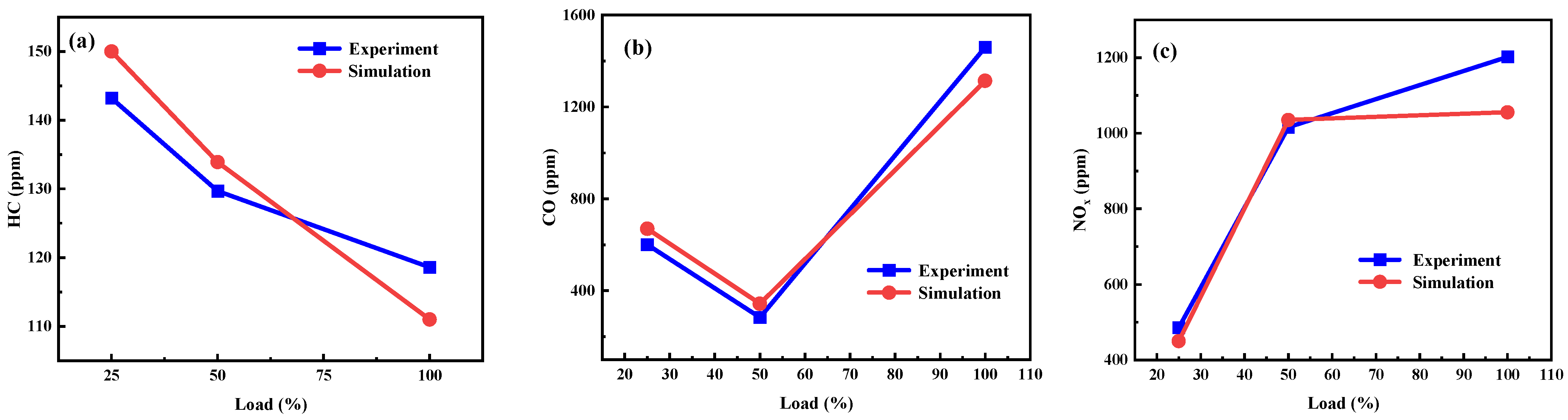
3.4. Model Validation

Numerical results always need to be validated with reference to experimental results. In this experimental study, the engine speed was 1000 rpm and the intake air temperature was kept constant during the experiment. The comparison of experimental and simulation results regarding in-cylinder pressure, HRR and NOx, HC, CO emissions at different loads are given in Figure 5a,b and Figure 6a,b. It can be seen that the pressure results obtained from the numerical study were in good agreement with the experimental study. There are some differences between the modelled and experimental results regarding the HRR and the emissions. But the general trend is consistent. Thus, it is shown that this model could be used for subsequent numerical simulations.

3.5. Error and Uncertainty Analysis

Generally speaking, the accuracy of an experiment is determined by the error and uncertainty of the test. The experimental strategy, conditions, sensor selection, etc. can all lead to experimental errors (as shown in Table 8).

4. Results and Discussions

4.1. Combustion Characteristics

In this section, the combustion characteristics of diesel engine under different CRs of different fuels are investigated in terms of in-cylinder pressure, HRR, and in-cylinder temperature.

4.1.1. In-Cylinder Pressure

The pressure trajectories in the cylinder of a diesel-hydrogen co-combustion engine are given when HES are 0%, 5%, 10% and 15%, respectively. It can be seen from Figure 7a that as the HES increased, the maximum combustion pressure was higher. The maximum Pmax for the operating condition with 15% hydrogen energy share was 8.87 MPa, which was 0.85 MPa higher than the pure diesel operation. This trend is consistent with the findings of Cernat et al. [67]. The in-cylinder pressure variation curve and the HRR variation curve reflect the nature of the in-cylinder combustion process of the dual-fuel engine. Hydrogen burns quickly due to the higher flame speed, increasing the rate of pressure rise as well as the pressure peak [68]. In addition, it can be noticed that after hydrogenation, the pressure peak appears earlier. As the HES increased, the pressure peak occurred earlier. It can be concluded that increasing the HES has a positive effect on in-cylinder pressure.
The results obtained by varying the value of the CR in the range of 14–20 while keeping the HES as 5% are shown in Figure 7b. It can be seen that after increasing the CR, the in-cylinder pressure became much larger, which was consistent with the trend of in-cylinder pressure change when the CR was fixed and the HES was changed. However, it is more obvious that changing the CR had a greater effect on the in-cylinder pressure. When the CR changed from 14 to 20, the in-cylinder pressure rose from 8.26 MPa to 13.72 MPa. The combustion of hydrogen fuel occurs mainly in the premixing stage. This is because the increase in CR results in a better mixing of the fuel and a rise in temperature during compression. During this process, the fuel reacts more quickly, resulting in a rapid increase in temperature in the cylinder.

4.1.2. Heat Release Rate (HRR)

The HRR consists of three distinct phases. In the first stage, the HRR reaches a first peak as the pressure rises sharply, and rapid combustion occurs. In this stage, most of the diesel fuel and a small portion of the hydrogen fuel are premixed and burned to give off heat. In the second stage, as the temperature and pressure increase, the second peak in the HRR occurs when the fuel reaches enough oxygen for a flame to form quickly in the cylinder. In the last stage, when sufficient oxygen is available, the unburned fuel or partially burned components in the combustion chamber in the previous stages continue to burn. A final heat release occurs.
The following conclusions were drawn from Figure 8a. Throughout the process of combustion, there were three more pronounced peaks. The peak values of HRR were increased under hydrogenation conditions compared to pure diesel. In addition, the peak of the HRR increased with increasing HES. This is because hydrogen diffused faster and hydrogen and air can mix more fully. This is consistent with the conclusion reached by Khandal et al. [69]. They concluded that the HRR and peak pressure were higher than the conventional model due to the fast combustion rate of hydrogen.
As shown in Figure 8b, the peak HRR decreased as the CR increased, and the peak appeared earlier. This is due to improved combustion efficiency and shorter ignition delay. With a certain percentage of hydrogen mass, the engine is prone to violent combustion and knocking. However, there is a trade-off between the CR and the HES, and a lower CR increases the share of hydrogen energy required to satisfy the non-knocking cylinder requirement [70].

4.1.3. In-Cylinder Temperature

As shown in Figure 9a, compared to pure diesel operation, the temperature in the cylinder increased from 1370 K to 1580 K with the HES of 15%. At all operating conditions, the peak in-cylinder temperature occurred at 0–10 deg. As hydrogen was added, the cylinder temperature rose. However, during combustion, the relationship between the amount of hydrogen added and the in-cylinder temperature was reversed. In the early stage, the bigger the HES, the lower the cylinder temperature became. However, at the crank angle of −3.09 deg, the addition of hydrogen still increased the cylinder temperature. However, the more hydrogen added, the higher the cylinder temperature. This is due to the fact that a large amount of hydrogen has been ignited and it burns very fast, so the temperature in the cylinder rises dramatically.
As can be seen from Figure 9b, the temperature in the cylinder had risen due to the increase in the CR. At higher CRs, the increased flame speed also contributed to the combustion of the end gas mixture. When the compression temperature was higher, the combustion delay was shorter. The shorter the combustion duration, the more efficient the combustion process. This improved high temperature combustion process increased the conversion efficiency.

4.2. Emission Characteristic
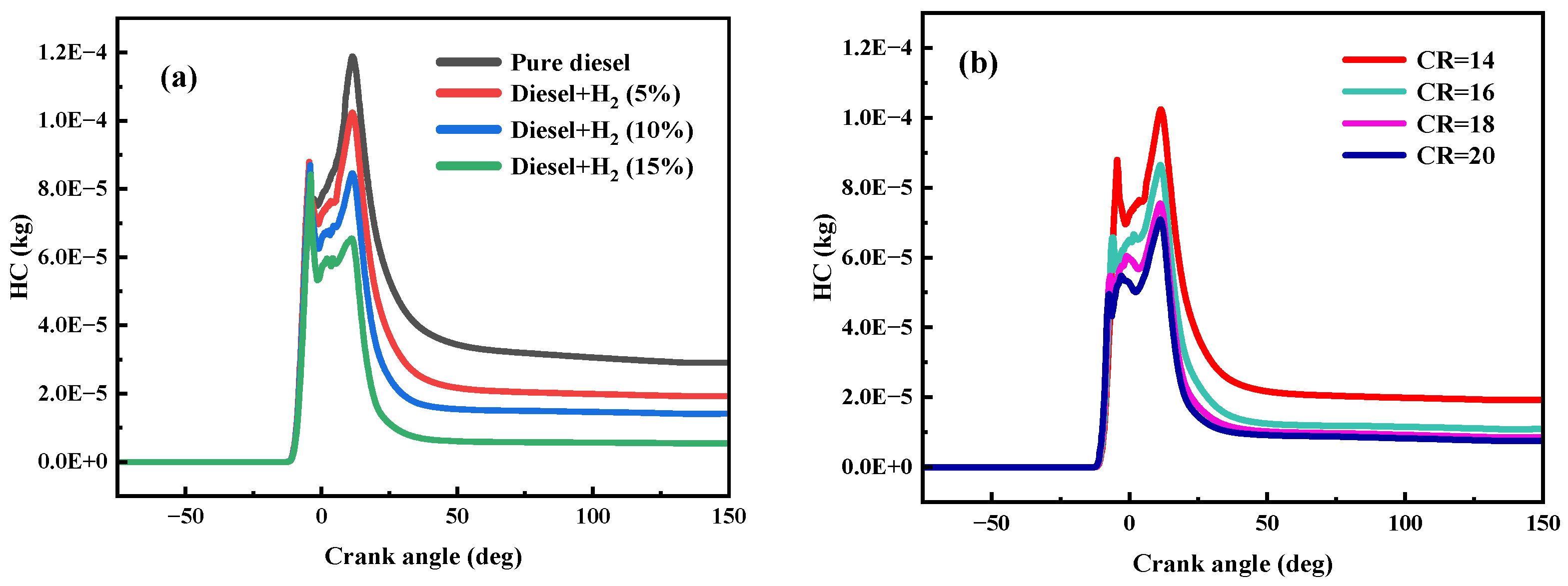
This section discusses the effect of different fuel blends on the emission characteristics of the engine under different HES conditions and different CRs in terms of NOx, HC, CO, CO2, and soot emissions.

4.2.1. HC Emission

The effects of hydrogenation and CR on HC emissions are shown in Figure 10a,b. Compared to the diesel-only model, HC emission was significantly lower for each set of simulations after hydrogen addition. And, the HC emission decreased more with increasing hydrogen addition. As can be seen from the above graph, the peak of HC emission occurred later as the HES increased. HC is produced by incomplete combustion in the cylinder and is mainly generated at lower combustion chamber temperatures. After hydrogenation, HC emission is effectively reduced because hydrogen gas does not contain carbon atoms and because the amount of diesel fuel injected is reduced. In addition, hydrogen has a faster flame spread and more intense combustion. Compared with pure diesel engines, hydrogen–diesel dual-fuel engines contribute to complete combustion.
As the CR increased, the engine’s HC emission reduced, increasing the efficiency of the engine cycle. This is because the flame propagates faster and the combustion process is shortened. This increases the boost temperature and, as a result, reduces the quenching of the flame, which in turn reduces the HC emission. Increasing the CR increases the temperature during compression and reduces the ignition delay time. In addition, higher combustion temperatures contribute to better combustion and reduced HC emissions. Increasing the CR from 14 to 16, 18, and 20 reduced HC emissions by 43.0%, 55.6%, and 60.0%, respectively.

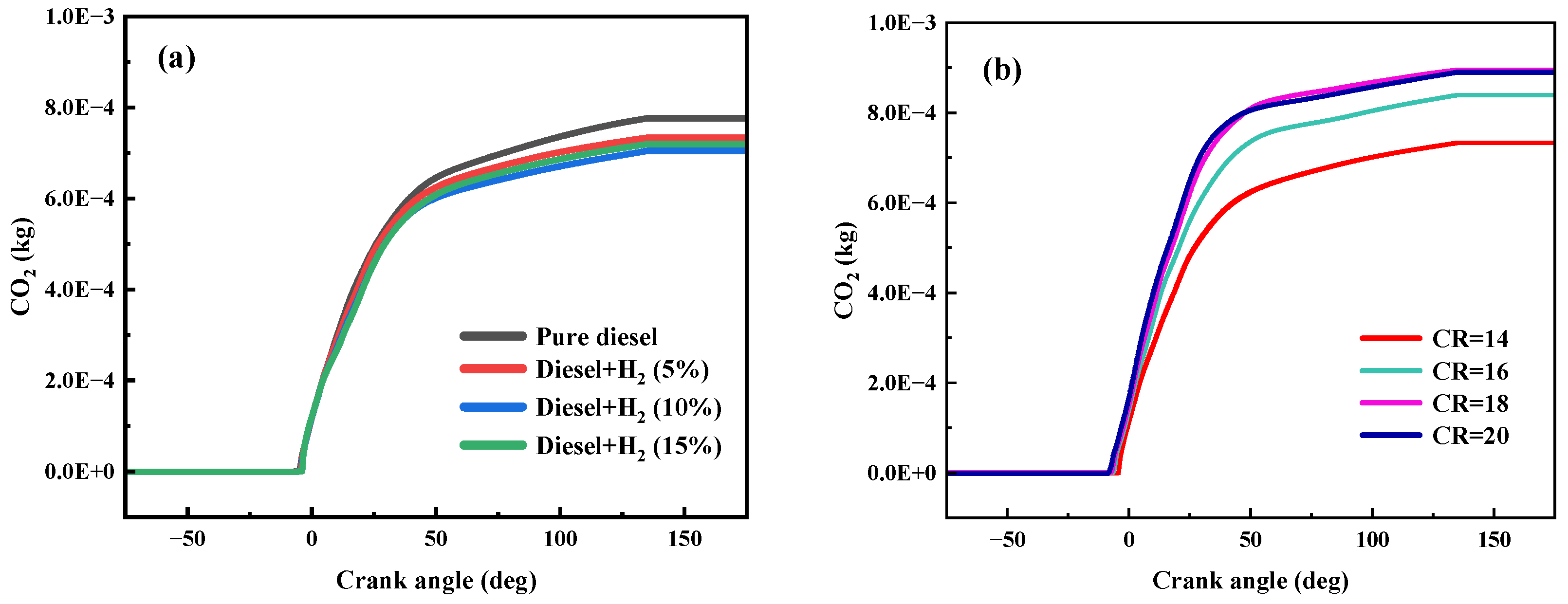
4.2.2. CO and CO2 Emissions

CO emission is the result of incomplete combustion, an intermediate product produced by insufficient oxygen. As can be seen from Figure 11a,b, CO emissions were relatively low, even under the pure diesel condition. This is because diesel engines support lean combustion. Although there is a localized oxygen deficiency zone in the diesel engine, the average excess air coefficient is greater than 1, and there is enough air in the cylinder to oxidize the CO formed. In addition, with the increase in hydrogenation, the CO emission decreased. This is due to the high diffusion coefficient of hydrogen, which makes the combustible mixture more homogeneous and more favorable for combustion. And, after hydrogenation, the cylinder temperature rose, which also made combustion more complete.
As the CR increased, CO emission were greatly reduced. Temperatures and pressures near the TDC were naturally higher as the CR increased. At high loads, the temperature typically increased the rate of chemical kinetics. When increasing the CR from 14 to 16, 18, and 20, the CO emissions were reduced by 22.3%, 35.4%, and 33.6%, respectively.
The pattern of CO2 emission change after hydrogenation is very obvious. It can be seen from Figure 12a that there was a significant decrease in CO2 emission. And, with the increase of the HES, the CO2 emission reduced. There are several reasons to consider for this phenomenon. The first is that hydrogen has been added to the fuel, which contains no carbon atoms. Then, the carbon-to-hydrogen ratio of the total fuel decreases, the combustion duration is shortened, and the combustion efficiency is increased. Finally, it is also considered that hydrogen has a high diffusion coefficient, and this improves the inhomogeneity of the diesel fuel.
As shown in Figure 12b, the effect of CO2 emissions with an increasing CR is opposite to that of the CO emission. The increase in the CR leads to higher cylinder pressure and temperature, which promote further oxidation of CO and more complete combustion.

4.2.3. NOx Emission

Hydrogenation reduces HC, CO, and CO2 emissions, but it increases NOx emission, which is one of the biggest drawbacks of hydrogenation. As shown in Figure 13a, NOx emission rose sharply after hydrogenation. And, the more hydrogen that was added, the higher the NOx emission. Compared with the pure diesel operation, the NOx emission increases by 41.9%, 82.1%, and 166.9% for an HES of 5%, 10%, and 15%, respectively. This is due to the fact that the addition of hydrogen leads to faster combustion and higher temperatures and pressures in the cylinder. NOx emission is mainly determined by the oxygen concentration, local temperature, and reaction time. As the combustion temperature increases, the reactivity between the nitrogen and oxygen atoms increases. When H2 is introduced in the combustion chamber, the NOx emission increases significantly. The reason behind this situation can be explained by the fact that the calorific value of H2 gas is significantly higher than that of diesel fuel. In this case, hydrogen ensures high pressure rates and high in-cylinder temperatures. As the combustion temperature increases, the reactivity between the nitrogen and oxygen atoms increases, leading to an increase in NOx emissions.
This is in agreement with the trend of the experimental findings of Zhang et al. [71]. In that study, increasing hydrogen substitution compared to pure diesel reduced the formation of CO and CO2, but the NOx emission rose.
As shown in Figure 13b, with the increase in the CR, the cylinder temperature increased significantly and, therefore, NOx emissions increased. With the increase in CR, NOx emissions rose by at least 48.23%. Because of the increased CR, the fuel combustion environment is more ideal, and the fuel in the combustion chamber burns more completely.
Hydrogen plays an important role in dual-fuel engines as an alternative fuel and clean energy source [72]. However, high NOx emission is a major problem in hydrogen applications. This problem has been studied before. Serrano et al. [73] injected water into the intake manifold in order to control NOx emission, intake auto-ignition, and combustion detonation. They found that NOx emission rose as the H2/diesel ratio increased. However, with the water injection operation, NOx emission was reduced by about 50%. NOx emission can be reduced by using EGR technology. In addition, the SCR technology has been widely used for the removal of NOx. However, the development of low-temperature SCR catalysts with high removal efficiencies still faces serious challenges. Due to the excellent denitrification ability of manganese-based catalysts at low temperatures, Zhang et al. [74] concluded that the catalytic activity of manganese-based catalysts could be significantly improved by doping other metals or loading manganese-based catalysts on other metal oxides. NOx emission increased significantly with the increase in CR, as shown in Figure 13b. This is because as CR rises, so does the temperature inside the cylinder. More NOx is produced when there is enough oxygen.

4.2.4. Soot Emission

In this paper, soot emissions have been measured using a filter paper smoke meter, and the Filter paper smoke number (FNS) characterization method has been chosen. The FNS is dimensionless [75]. The specific conversion formula is as follows:
C mg / m 3 = 1 0.405 · 4.95 · F S N · e x p ( 0.38 F S N )
Converting this formula gives the amount of carbon soot contained in each cubic meter of exhaust.
As can be seen from the following figures, a portion of the soot generated in the engine cylinder is oxidized before it is discharged. Diesel combustion occurs at the beginning of the premixed combustion stage. Combustion is more complete, and the generation of soot is reduced. But at this time, the combustion temperature is lower, and the oxidation rate of soot is also lower. So the net amount of soot is on the rise. When it enters the diffusion combustion stage, a localized oxygen deficiency region occurs due to the increase in the cylinder temperature. The rate of soot generation is much higher than its oxidation rate, so the net amount of soot is greatly increased. When the soot grows to a certain peak, the oxidation rate of the soot begins to be greater than the rate of its generation, and then the net soot begins to decline.
Analyzing the data in Figure 14a shows that as more hydrogen was added, the soot emission decreased. This is because hydrogen allows the flame to propagate quickly and the fuel mixture to burn more fully, reducing localized areas of oxygen deficiency.
There are two main dangers of soot. The first is the further formation of PM that pollutes the air. Then, soot may also mix into the oil, causing the oil quality to deteriorate. From Figure 14b, it can be seen that increasing the compression ratio could effectively reduce the soot emission, and the soot emission decreased with the increasing CR.

5. Conclusions

In this work, the effects of HES on the combustion characteristics and emission characteristics of diesel–hydrogen dual fuel with different CRs were investigated by a verified model. The values of the HES and CR were taken in the ranges of 0–15% and 14–20, respectively. The obtained results of the numerical study are as follows:
(1)
Hydrogenation improves combustion characteristics. The in-cylinder pressure increased by 10.54% when the HES reached 15% compared to when no hydrogen was added. And, the in-cylinder temperature increased by 15.11%. Hydrogenation is also good for improving emission characteristics. HC emission, CO emission, CO2 emission, and soot emission can be reduced.
(2)
Increasing CR has benefits for both combustion characteristics and emission characteristics. The simulation results show that the in-cylinder pressure and in-cylinder temperature increased by 66.10% and 13.09%, respectively, when the CR rose from 14 to 20 at the HES of 5%.
(3)
It should be also noted that NOx emission increased after hydrogenation, which is one of the biggest problems after hydrogenation. Higher in-cylinder temperatures and in-cylinder pressures lead to increased NOx emission.
In conclusion, increasing the HES and CR has a positive effect on diesel engine performance, combustion characteristics, and emission characteristics. However, after hydrogenation to a certain percentage of the hydrogen mass, the engine is prone to harsh combustion and knocking. And, high emission of NOx is also a problem that needs to be solved. In the future, diesel engine designers will also need to experimentally study the interaction of HES, CR, and other factors to obtain a superior combination of operating conditions.

Author Contributions

Conceptualization, S.W. and J.L.; methodology, S.W. and J.L.; software, S.W. and J.L.; validation, S.W. and S.G.; formal analysis, S.W.; investigation, S.W. and Z.L.; resources, Z.L. and S.G.; data curation, S.W.; writing—original draft preparation, S.W.; writing—review and editing, S.W. and J.H.; visualization, S.W., J.H., J.Z., W.Z. and Z.Z.; supervision, Y.L.; project administration, S.W and Y.L.; funding acquisition, Y.L. All authors have read and agreed to the published version of the manuscript.

Funding

This research is supported by the High-Level Talent Research Fund of Yulin Normal University under the research grants of G2018002.

Data Availability Statement

All relevant data are within the paper.

Conflicts of Interest

The authors declare no conflict of interest.

References

  1. Zhang, Z.; Li, J.; Tian, J.; Dong, R.; Zou, Z.; Gao, S.; Tan, D. Performance, combustion and emission characteristics investigations on a diesel engine fueled with diesel/ethanol/n-butanol blends. Energy 2022, 249, 123733. [Google Scholar] [CrossRef]
  2. Hassan, Q.; Sameen, A.; Olapade, O.; Alghoul, M.; Salman, H.; Jaszczur, M. Hydrogen fuel as an important element of the energy storage needs for future smart cities. Int. J. Hydrogen Energy 2023, in press. [Google Scholar] [CrossRef]
  3. Guan, Y.; Zhao, D. Enhancing ammonia combustion with minimum hydrogen blended in presence of self-excited intermittent pulsating oscillations. Phys. Fluids 2023, 35, 054102. [Google Scholar] [CrossRef]
  4. Muniyappan, M.; Tamil, P.S.; Gopi, P.; Shanmugam, M.; Bhuvendran, A.; Shaisundaram, V.S. Hydrogen behavior in dual fuel mode diesel engine with nano diesel. Mater. Today 2021, 37, 2401–2405. [Google Scholar] [CrossRef]
  5. Roy, A.; Pramanik, S. A review of the hydrogen fuel path to emission reduction in the surface transport industry. Int. J. Hydrogen Energy 2023, in press. [Google Scholar] [CrossRef]
  6. Tarafdar, A.; Majumder, P.; Deb, M.; Bera, U.K. Performance-emission optimization in a single cylinder CI-engine with diesel hydrogen dual fuel: A spherical fuzzy MARCOS MCGDM based Type-3 fuzzy logic approach. Int. J. Hydrogen Energy 2023, in press. [Google Scholar] [CrossRef]
  7. Lalsangi, S.; Yaliwal, V.S.; Banapurmath, N.R.; Soudagar, M.E.M.; Ağbulut, Ü.; Kalam, M.A. Analysis of CRDI diesel engine characteristics operated on dual fuel mode fueled with biodiesel-hydrogen enriched producer gas under the single and multi-injection scheme. Int. J. Hydrogen Energy 2023, in press. [Google Scholar] [CrossRef]
  8. Shi, Z.; Peng, Q.; E, J.; Xie, B.; Wei, J.; Yin, R.; Wei, J.; Yin, R.; Fu, G. Mechanism, performance and modification methods for NH3-SCR catalysts: A review. Fuel 2023, 331, 125885. [Google Scholar] [CrossRef]
  9. Ye, J.; Peng, Q. Improved emissions conversion of diesel oxidation catalyst using multifactor impact analysis and neural network. Energy 2023, 271, 127048. [Google Scholar] [CrossRef]
  10. Zhang, Z.; Tian, J.; Xie, G.; Li, J.; Xu, W.; Jiang, F.; Huang, Y.; Tan, D. Investigation on the combustion and emission characteristics of diesel engine fueled with diesel/methanol/n-butanol blends. Fuel 2022, 314, 123088. [Google Scholar] [CrossRef]
  11. Zhang, Z.; Dong, R.; Tan, D.; Duan, L.; Jiang, F.; Yao, X.; Yang, D.; Hu, J.; Zhong, W.; Zhao, Z. Effect of structural parameters on diesel particulate filter trapping performance of heavy-duty diesel engines based on grey correlation analysis. Energy 2023, 271, 127025. [Google Scholar] [CrossRef]
  12. Barik, D.; Bora, B.J.; Sharma, P.; Medhi, B.J.; Balasubramanian, D.; Krupakaran, R.L.; Ramegowda, R.; Kavalli, K.; Josephin, F.; Vikneswaran, M.; et al. Exploration of the dual fuel combustion mode on a direct injection diesel engine powered with hydrogen as gaseous fuel in port injection and diesel-diethyl ether blend as liquid fuel. Int. J. Hydrogen Energy 2023, in press. [Google Scholar] [CrossRef]
  13. Nag, S.; Dhar, A.; Gupta, A. Hydrogen-diesel co-combustion characteristics, vibro-acoustics and unregulated emissions in EGR assisted dual fuel engine. Fuel 2022, 307, 121925. [Google Scholar] [CrossRef]
  14. Zhang, Z.; Ye, J.; Tan, D.; Feng, Z.; Luo, J.; Tan, Y.; Hu, Y. The effects of Fe2O3 based DOC and SCR catalyst on the combustion and emission characteristics of a diesel engine fueled with biodiesel. Fuel 2021, 290, 120039. [Google Scholar] [CrossRef]
  15. Liu, Z.; Luo, J.; Pan, Y.; Li, J.; Li, L.; Wei, X.; Xu, H.; Tie, Y.; Zhang, C.; Yang, D. Multi-objective optimization of the performance and emission characteristics for a dual-fuel engine with hydrogen addition. Fuel 2023, 332, 126231. [Google Scholar] [CrossRef]
  16. Raju, P.; Masimalai, S.K.; Ganesan, N.; Karthic, S.V. Engine’s behavior on hydrogen addition of waste cooking oil fueled light duty diesel engine—A dual fuel approach. Energy 2020, 194, 116844. [Google Scholar] [CrossRef]
  17. Zhang, Z.; E, J.; Deng, Y.; MinhHieu, P.; Zuo, W.; Peng, Y.; Yin, Z. Effects of fatty acid methyl esters proportion on combustion and emission characteristics of a biodiesel fueled marine diesel engine. Energy Convers. Manag. 2018, 159, 244–253. [Google Scholar] [CrossRef]
  18. Tripathi, G.; Sharma, P.; Dhar, A. Computational study of diesel injection strategies for methane-diesel dual fuel engine. Eng. Technol. 2022, 6, 100393. [Google Scholar] [CrossRef]
  19. Tan, D.; Meng, Y.; Tian, J.; Zhang, C.; Zhang, Z.; Yang, G.; Cui, X.; Hu, J.; Zhao, Z. Utilization of renewable and sustainable diesel/methanol/n-butanol (DMB) blends for reducing the engine emissions in a diesel engine with different pre-injection strategies. Energy 2023, 269, 126785. [Google Scholar] [CrossRef]
  20. Zhang, Z.; Tian, J.; Xie, G.; Li, J.; Xu, W.; Jiang, F.; Huang, Y.; Tan, D. Investigation on the combustion and emission characteristics of diesel engine fueled with diesel/alcohol/ n-butanol blends. Fuel 2022, 314, 123975. [Google Scholar] [CrossRef]
  21. Wang, S.; Zhang, Z.; Hou, X.; Lv, J.; Lan, G.; Yang, G.; Hu, J. The environmental potential of hydrogen addition as complementation for diesel and biodiesel: A comprehensive review and perspectives. Fuel 2023, 342, 127794. [Google Scholar] [CrossRef]
  22. Kumar, M.V.; Babu, A.V.; Kumar, P.R. Experimental investigation on the effects of diesel and mahua biodiesel blended fuel in direct injection diesel engine modified by nozzle orifice diameters. Renew. Energ. 2018, 119, 388–399. [Google Scholar] [CrossRef]
  23. Kumar, M.V.; Reddy, T.S.; Reddy, C.R.; Reddy, S.; Alsharef, M.; Alharbi, Y.; Alamri, B. Impact of a Thermal Barrier Coating in Low Heat Rejection Environment Area of a Diesel Engine. Sustainability 2022, 14, 15801. [Google Scholar] [CrossRef]
  24. Chintala, V.; Subramanian, K.A. Hydrogen energy share improvement along with NOx (oxides of nitrogen) emission reduction in a hydrogen dual-fuel compression ignition engine using water injection. Energy Convers. Manag. 2014, 83, 249–259. [Google Scholar] [CrossRef]
  25. Nag, S.; Sharma, P.; Gupta, A.; Dhar, A. Experimental study of engine performance and emissions for hydrogen diesel dual fuel engine with exhaust gas recirculation. Energy Convers. Manag. 2019, 44, 12163–12175. [Google Scholar] [CrossRef]
  26. Suzuki, Y.; Tsujimura, T.; Mita, T. The Performance of Multi-Cylinder Hydrogen/Diesel Dual Fuel Engine. SAE Int. J. Engines 2015, 8, 2240–2252. [Google Scholar] [CrossRef]
  27. Seelam, N.; Gugulothu, S.K.; Reddy, R.V.; Bhasker, B.; Panda, J.K. Exploration of engine characteristics in a CRDI diesel engine enriched with hydrogen in dual fuel mode using toroidal combustion chamber. Int. J. Hydrogen Energy 2022, 47, 13157–13167. [Google Scholar] [CrossRef]
  28. Ekin, F.; Ozsoysal, O.A.; Arslan, H. The effect of using hydrogen at partial load in a diesel-natural gas dual fuel engine. Int. J. Hydrogen Energy 2022, 47, 18532–18550. [Google Scholar] [CrossRef]
  29. Chintala, V.; Subramanian, K.A. CFD analysis on effect of localized in-cylinder temperature on nitric oxide (NO) emission in a compression ignition engine under hydrogen-diesel dual-fuel mode. Energy 2016, 116, 470–488. [Google Scholar] [CrossRef]
  30. Saravana, N.; Nagarajan, G.; Kalaiselvan, K.M.; Dhanasekaran, C. An experimental investigation on hydrogen as a dual fuel for diesel engine system with exhaust gas recirculation technique. Renew. Energy 2008, 33, 422–427. [Google Scholar] [CrossRef]
  31. Sathishkumar, S.; Ibrahim, M.M. Investigation on the effect of injection schedule and EGR in hydrogen energy share using common rail direct injection dual fuel engine. Int. J. Hydrogen Energy 2021, 46, 11494–11510. [Google Scholar] [CrossRef]
  32. Zhang, Z.; Lv, J.; Xie, G.; Wang, S.; Ye, Y.; Huang, G.; Tan, D. Effect of assisted hydrogen on combustion and emission characteristics of a diesel engine fueled with biodiesel. Energy 2022, 254, 124269. [Google Scholar] [CrossRef]
  33. Dimitriou, P.; Tsujimura, T.; Suzuki, Y. Low-load hydrogen-diesel dual-fuel engine operation—A combustion efficiency improvement approach. Int. J. Hydrogen Energy 2019, 44, 17048–17060. [Google Scholar] [CrossRef]
  34. Hamdan, M.O.; Selim, M.Y.E.; Al-Omari, S.; Elnajjar, E. Hydrogen supplement co-combustion with diesel in compression ignition engine. Renew. Energy 2015, 82, 54–60. [Google Scholar] [CrossRef]
  35. Jamrozik, A.; Grab-Rogaliński, K.; Tutak, W. Hydrogen effects on combustion stability, performance and emission of diesel engine. Int. J. Hydrogen Energy 2020, 45, 19936–19947. [Google Scholar] [CrossRef]
  36. Koten, H. Hydrogen effects on the diesel engine performance and emissions. Int. J. Hydrogen Energy 2018, 43, 10511–10519. [Google Scholar] [CrossRef]
  37. Juknelevičius, R.; Rimkus, A.; Pukalskas, S.; Matijošius, J. Research of performance and emission indicators of the compression-ignition engine powered by hydrogen—Diesel mixtures. Int. J. Hydrogen Energy 2019, 44, 10129–10138. [Google Scholar] [CrossRef]
  38. Karagöz, Y.; Sandalcı, T.; Yüksek, L.; Dalkılıç, A.S. Engine performance and emission effects of diesel burns enriched by hydrogen on different engine loads. Int. J. Hydrogen Energy 2015, 40, 6702–6713. [Google Scholar] [CrossRef]
  39. Rahman, M.A.; Ruhul, A.M.; Aziz, M.A.; Ahmed, R. Experimental exploration of hydrogen enrichment in a dual fuel CI engine with exhaust gas recirculation. Int. J. Hydrogen Energy 2017, 42, 5400–5409. [Google Scholar] [CrossRef]
  40. Ghazal, O.H. Performance and combustion characteristic of CI engine fueled with hydrogen enriched diesel. Int. J. Hydrogen Energy 2013, 38, 15469–15476. [Google Scholar] [CrossRef]
  41. Juknelevicius, R.; Szwaja, S.; Pyrc, M.; Gruca, M. Influence of hydrogen co-combustion with diesel fuel on performance, smoke and combustion phases in the compression ignition engine. Int. J. Hydrogen Energy 2019, 44, 19026–19034. [Google Scholar] [CrossRef]
  42. Kumar, A.; Bhushan, K.C.; Lata, D.B. Effect of hydrogen enrichment on exhaust gas temperature and emission of a dual fuel diesel engine. Mater. Today 2023, 72, 631–635. [Google Scholar] [CrossRef]
  43. Castro, N.; Toledo, M.; Amador, G. An experimental investigation of the performance and emissions of a hydrogen-diesel dual fuel compression ignition internal combustion engine. Appl. Therm. Eng. 2019, 156, 660–667. [Google Scholar] [CrossRef]
  44. Verma, S.; Das, L.M.; Kaushik, S.C.; Bhattii, S.S. The effects of compression ratio and EGR on the performance and emission characteristics of diesel-biogas dual fuel engine. Appl. Therm. Eng. 2019, 150, 1090–1103. [Google Scholar] [CrossRef]
  45. Dahake, M.R.; Malkhede, D.N. Experimental investigation of performance and emissions of CRDI diesel engine in dual fuel mode by hydrogen induction and diesel injection coupled with exhaust gas recirculation. Mater. Today 2021, 46, 2814–2819. [Google Scholar] [CrossRef]
  46. Tan, D.; Wu, Y.; Lv, J.; Li, J.; Ou, X.; Meng, Y.; Lan, G.; Chen, Y.; Zhang, Z. Performance optimization of a diesel engine fueled with hydrogen/biodiesel with water addition based on the response surface methodology. Energy 2023, 263, 125869. [Google Scholar] [CrossRef]
  47. Kumar, M.; Bhowmik, S.; Paul, A. Effect of pilot fuel injection pressure and injection timing on combustion, performance and emission of hydrogen-biodiesel dual fuel engine. Int. J. Hydrogen Energy 2022, 47, 29554–29567. [Google Scholar] [CrossRef]
  48. Karimi, M.; Wang, X.; Hamilton, J.; Negnevitsky, M. Numerical investigation on hydrogen-diesel dual-fuel engine improvements by oxygen enrichment. Int. J. Hydrogen Energy 2022, 47, 25418–25432. [Google Scholar] [CrossRef]
  49. Dimitriou, P.; Kumar, M.; Tsujimura, T.; Suzuki, Y. Combustion and emission characteristics of a hydrogen-diesel dual-fuel engine. Int. J. Hydrogen Energy 2018, 43, 13605–13617. [Google Scholar] [CrossRef]
  50. Verma, S.; Suman, A.; Das, L.M.; Kaushik, S.C.; Tyagi, S.K. A renewable pathway towards increased utilization of hydrogen in diesel engines. Int. J. Hydrogen Energy 2020, 45, 5577–5587. [Google Scholar] [CrossRef]
  51. Kumar, M.; Babu, A.; Reddy, C.; Pandian, A.; Bajaj, M.; Zawbaa, H.; Kamel, S. Investigation of the combustion of exhaust gas recirculation in diesel engines with a particulate filter and selective catalytic reactor technologies for environmental gas reduction. Case Stud. Therm. Eng. 2022, 40, 102557. [Google Scholar] [CrossRef]
  52. Gürbüz, H. Analysis of the effects of multiple injection strategies with hydrogen on engine performance and emissions in diesel engine. Int. J. Hydrogen Energy 2020, 45, 27969–27978. [Google Scholar] [CrossRef]
  53. Tripathi, G.; Sharma, P.; Dhar, A.; Sadiki, A. Computational investigation of diesel injection strategies in hydrogen-diesel dual fuel engine. Sustain. Energy Techn. 2019, 36, 100543. [Google Scholar] [CrossRef]
  54. Yusri, I.M.; Abdul, M.A.; Mamat, R.; Ghazali, M.F.; Awad, O.I.; Azmi, W.H. A review on the application of response surface method and artificial neural network in engine performance and exhaust emissions characteristics in alternative fuel. Renew. Sust. Energ. Rev. 2018, 90, 665–686. [Google Scholar] [CrossRef]
  55. Goyal, D.; Goyal, T.; Mahla, S.K.; Goga, G.; Dhir, A.; Balasubramanian, D.; Hoang, A.T.; Wae-Hayee, M.; Josephin, J.S.F.; Sonthalia, A.; et al. Application of Taguchi design in optimization of performance and emissions characteristics of n-butanol/diesel/biogas under dual fuel mode. Fuel 2023, 338, 127246. [Google Scholar] [CrossRef]
  56. Sharma, P.; Sharma, A.K. Application of Response Surface Methodology for Optimization of Fuel Injection Parameters of a Dual Fuel Engine Fuelled with Producer Gas-Biodiesel blends. Energ. Source. Part A. 2021. [Google Scholar] [CrossRef]
  57. Bora, B.J.; Tran, T.D.; Shadangi, K.P.; Sharma, P.; Said, Z.; Kalita, P.; Buradi, A.; Nguyen, V.N.; Niyas, H.; Pham, M.T.; et al. Improving combustion and emission characteristics of a biogas/biodiesel-powered dual-fuel diesel engine through trade-off analysis of operation parameters using response surface methodology. Sustain. Energy Technol. Assess. 2022, 53, 102455. [Google Scholar] [CrossRef]
  58. Zhang, Z.; Hu, J.; Tan, D.; Li, J.; Jiang, F.; Yao, X.; Yang, D.; Ye, Y.; Zhao, Z.; Yang, G. Multi-objective optimization of the three-way catalytic converter on the combustion and emission characteristics for a gasoline engine. Energy 2023, 277, 127634. [Google Scholar] [CrossRef]
  59. Wang, H.; Gan, H.; Wang, G.; Zhong, G. Emission and Performance Optimization of Marine Four-Stroke Dual-Fuel Engine Based on Response Surface Methodology. Math. Probl. Eng. 2020, 2020, 5268314. [Google Scholar] [CrossRef]
  60. Lotfan, S.; Ghiasi, R.A.; Fallah, M.; Sadeghi, M.H. ANN-based modeling and reducing dual-fuel engine’s challenging emissions by multi-objective evolutionary algorithm NSGA-II. Appl. Energy 2016, 175, 91–99. [Google Scholar] [CrossRef]
  61. Yu, W.; Zhao, F. Predictive study of ultra-low emissions from dual-fuel engine using artificial neural networks combined with genetic algorithm. Int. J. Green Energy 2019, 16, 938–946. [Google Scholar] [CrossRef]
  62. Xiang, L.; Theotokatos, G.; Ding, Y. Parametric investigation on the performance-emissions trade-off and knocking occurrence of dual fuel engines using CFD. Fuel 2023, 340, 127535. [Google Scholar] [CrossRef]
  63. Zhang, Z.; Lv, J.; Li, W.; Long, J.; Wang, S.; Tan, D.; Yin, Z. Performance and emission evaluation of a marine diesel engine fueled with natural gas ignited by biodiesel-diesel blended fuel. Energy 2022, 256, 124662. [Google Scholar] [CrossRef]
  64. Zareei, J.; Haseeb, M.; Ghadamkheir, K.; Farkhondeh, S.A.; Yazdani, A.; Ershov, K. The effect of hydrogen addition to compressed natural gas on performance and emissions of a DI diesel engine by a numerical study. Int. J. Hydrogen Energy 2020, 45, 34241–34253. [Google Scholar] [CrossRef]
  65. Saravanan, N.; Nagarajan, G. Experimental investigation on a DI dual fuel engine with hydrogen injection. Int. J. Energy Res. 2009, 33, 295–308. [Google Scholar] [CrossRef]
  66. Raza, A.; Arif, M.; Glatz, G.; Mahmoud, M.; Al Kobaisi, M.; Alafnan, S.; Stefan, I. A holistic overview of underground hydrogen storage: Influencing factors, current understanding, and outlook. Fuel 2022, 330, 125336. [Google Scholar] [CrossRef]
  67. Cernat, A.; Pana, C.; Negurescu, N.; Nutu, C.; Fuiorescu, D.; Lazaroiu, G. Aspects of an experimental study of hydrogen use at automotive diesel engine. Heliyon 2023, 9, e13889. [Google Scholar] [CrossRef]
  68. Joseph, S.; Shanmugaiah, K.; Sonthalia, A.; Devarajan, Y.; Varuvel, E.G. Application of machine learning algorithms for predicting the engine characteristics of a wheat germ oil–Hydrogen fuelled dual fuel engine. Int. J. Hydrogen Energy 2023, 48, 23308–23322. [Google Scholar] [CrossRef]
  69. Khandal, S.V.; Ağbulut, Ü.; Afzal, A.; Sharifpur, M.; Abdul Razak, K.; Khalilpoor, N. Influences of hydrogen addition from different dual-fuel modes on engine behaviors. Energy Sci. Eng. 2022, 10, 881–891. [Google Scholar] [CrossRef]
  70. Sharma, P.; Dhar, A. Compression ratio influence on combustion and emissions characteristic of hydrogen diesel dual fuel CI engine: Numerical Study. Fuel 2018, 222, 852–858. [Google Scholar] [CrossRef]
  71. Zhang, B.; Wang, S.; Wang, H. Computational investigation of combustion, performance, and emissions of a diesel-hydrogen dual-fuel engine. Sustainability 2023, 15, 3610. [Google Scholar] [CrossRef]
  72. Bakar, R.A.; Widudo; Kadirgama, K.; Ramasamy, D.; Yusaf, T.; Kamarulzaman, M.K.; Sivaraos; Aslfattahi, N.; Samylingam, L.; Alwayzy, S.H. Experimental analysis on the performance, combustion/emission characteristics of a DI diesel engine using hydrogen in dual fuel mode. Int. J. Hydrogen Energy 2022, in press. [Google Scholar] [CrossRef]
  73. Serrano, J.; Jiménez-Espadafor, F.J.; López, A. Analysis of the effect of different hydrogen/diesel ratios on the performance and emissions of a modified compression ignition engine under dual-fuel mode with water injection. Hydrogen-diesel dual-fuel mode. Energy 2019, 172, 702–711. [Google Scholar] [CrossRef]
  74. Zhang, Z.; Li, J.; Tian, J.; Zhong, Y.; Zou, Z.; Dong, R.; Gao, S.; Xu, W.; Tan, D. The effects of Mn-based catalysts on the selective catalytic reduction of NOx with NH3 at low temperature: A review. Fuel Process. Technol. 2022, 230, 107213. [Google Scholar] [CrossRef]
  75. Zhou, Y. AVL 415 Filter Paper Smoke Meter Internal Comprehensive Training. 2012. Available online: https://wenku.baidu.com/view/1a28d7174835eefdc8d376eeaeaad1f34793117a.html?_wkts_=1693928158169 (accessed on 17 June 2023).
Figure 1. Flowchart of modeling and simulation.
Processes 11 02675 g001
Figure 2. CFD model of engine combustion chambers.
Processes 11 02675 g002
Figure 3. Comparison of cylinder pressure for grid independence test.
Processes 11 02675 g003
Figure 4. Schematic diagram of the experimental equipment.
Processes 11 02675 g004
Figure 5. Comparison of experimental and simulated in-cylinder pressure and HRR at different loads. (a) In-cylinder pressure; (b) HRR.
Processes 11 02675 g005
Figure 6. Comparison of experimental and simulated HC, CO, and NOx emissions at different loads. (a) HC emission; (b) CO emission; (c) NOx emission.
Processes 11 02675 g006
Figure 7. Effect of HES (CR = 14) and CR (HES = 5%) on in-cylinder pressure. (a) Effect of HES (CR = 14); (b) Effect of CR (HES = 5%).
Processes 11 02675 g007
Figure 8. Effect of HES (CR = 14) and CR (HES = 5%) on HRR. (a) Effect of HES (CR = 14); (b) Effect of CR (HES = 5%).
Processes 11 02675 g008
Figure 9. Effect of HES (CR = 14) and CR (HES = 5%) on in-cylinder temperature. (a) Effect of HES (CR = 14). (b) Effect of CR (HES = 5%).
Processes 11 02675 g009
Figure 10. Effect of HES (CR = 14) and CR (HES = 5%) on HC emission. (a) Effect of HES (CR = 14); (b) Effect of CR (HES = 5%).
Processes 11 02675 g010
Figure 11. Effect of HES (CR = 14) and CR (HES = 5%) on CO emission. (a) Effect of HES (CR = 14); (b) Effect of CR (HES = 5%).
Processes 11 02675 g011
Figure 12. Effect of HES (CR = 14) and CR (HES = 5%) on CO2 emission. (a) Effect of HES (CR = 14); (b) Effect of CR (HES = 5%).
Processes 11 02675 g012
Figure 13. Effect of HES (CR = 14) and CR (HES = 5%) on NOx emission. (a) Effect of HES (CR = 14); (b) Effect of CR (HES = 5%).
Processes 11 02675 g013
Figure 14. Effect of HES (CR = 14) and CR (HES = 5%) on soot emission. (a) Effect of HES (CR = 14); (b) Effect of CR (HES = 5%).
Processes 11 02675 g014
Table 1. Mathematical models and chemical mechanisms used in computational fluid dynamics (CFD) simulations.
Models/MechanismsSub-Model
Pilot injectionO′ Rurke
Spray break-upKH-RT model [11]
EvaporationFrossling model
Collision modelNTC model
CombustionSAGE model [62]
TurbulenceRNG k- ε [63]
NOx formationExtended Zeldovich Mechanism [64]
Soot formationHiroyasu-NSC soot model
Heat transferO’Rurke and Amsden
Table 2. Mesh control strategy.
Base Grid Size1.25 mm2 mm4 mm
Adaptive mesh
refinement
Max embedding levelSub-grid criterion
Velocity  2  2.0
Temperature  2  5
Fixed embedding   ScaleEmbed layers
Nozzles  2  -
Piston  1  1
Head  1  1
Table 3. Fuel physical properties.
ParameterDieselH2 [66]
Density (kg/m3, at 25 °C)833–8810.0838
Viscosity (Pa·s, at 25 °C)2.419 × 10−38.915 × 10−6
Octane number (-)15–25>130
Cetane number50--
Critical temperature (K)73633.19
Critical pressure (Mpa)--1.313
Auto-ignition temperature (K)530858
Theoretical air/fuel ratio (-)14.634.38
Flammability range in the air (%)0.5–4.14.1–75
Flame velocity in the air (cm/s)30265–325
Low calorific value (MJ/kg)42.8120.1
Table 4. Engine properties.
ParameterValue
Combustion systemFour-stroke diesel with direct injection
Number of cylinders4
Bore × stroke190 mm × 210 mm
Connecting rod length410 mm
Number of injector holes8
Injection hole diameter0.26 mm
Swept volume23.82 L
Compression ratio14
Engine speed1000 rpm
Torque210N·m
Effective power220 kW
Injection pressure40 MPa
Injection time−15°CA
Exhaust valve opening58°BBDC
Exhaust valve closing56°ATDC
Intake valve opening66°BTDC
Intake valve closing54°ABDC
Table 5. Operating conditions.
ParameterValue
Engine speed1000 rpm
Mass of fuel injection49 mg
Intake pressure0.157 Mpa
Intake temperature313.15 K
Hydrogen energy share0%5%10%15%
Mass flow rate of H205.5 kg/h11.0 kg/h16.5 kg/h
Compression ratio14161820
Table 6. Specifications of measurement instruments.
DeviceMeasuredPrecision
Electric dynamometerNIDY S22-2/05251BV-1Speed: ±2 r/min;
Torque: ±0.8% F.S
Dynamometer control systemPUMA OPEN1.4.1±0.8% FS
Diesel flowmeterTOCEIL CMFG0100.1%
Gas flowmeterTOCEIL 20 N125±0.8%
Temperature sensorThermojunction type±0.5 °C
Emission analyzer
(Horiba MEXA-1600DS)
HC, CO, CO2, NOx±1.0% F.S
Combustion analyzerDEWE-2010CA--
AVL GH13P Piezoelectric sensor0–25 MPa±0.3 kPa
AVL 415 S Filter Paper Smoke MeasurementSoot±0.1 FSN
Table 7. Experimental and simulation plan.
No.ParametersLoad %
1Diesel100
2Diesel + H2 (0% 5% 10% 15%), CR = 14100
3Diesel + H2 CR = 14, 16, 18, 20, HES = 5%100
Table 8. Lists of measurements, the measuring range, accuracy, and uncertainty.
MeasurementsMeasuring RangeAccuracyUncertainty (%)
Engine speed1–2000 rpm±0.2%±0.25
Pressure0–25 MPa±10 MPa±0.5
Exhaust temperature0–2000 °C±0.5 °C±0.25
NOx emission0–5000 ppm±10 ppm±0.48
THC emission0–20,000 ppm±10 ppm±0.12
CO emission0–10% vol±0.03%±0.38
Soot emission0–9 FSN±0.1 FSN±3.2
Disclaimer/Publisher’s Note: The statements, opinions and data contained in all publications are solely those of the individual author(s) and contributor(s) and not of MDPI and/or the editor(s). MDPI and/or the editor(s) disclaim responsibility for any injury to people or property resulting from any ideas, methods, instructions or products referred to in the content.

