Article

Thermo-Mechanical Numerical Analysis of Stress and Damage Distribution within the Surrounding Rock of Underground Coal Gasification Panels

1
College of Petroleum Engineering, China University of Petroleum, Beijing 102249, China
2
State Key Laboratory of Petroleum Resources & Engineering, Beijing 102249, China
3
Engineering and Technology Operating Center, Hainan Branch of CNOOC Ltd., Haikou 570100, China
4
Liaohe Oilfield Company of CNPC Ltd., Panjin 124010, China
5
Xibu Drilling Engineering Company of CNPC Ltd., Urumqi 830015, China
*
Author to whom correspondence should be addressed.
Processes 2023, 11(9), 2521; https://doi.org/10.3390/pr11092521
Submission received: 13 June 2023 / Revised: 9 August 2023 / Accepted: 21 August 2023 / Published: 22 August 2023
(This article belongs to the Special Issue Oil and Gas Drilling Rock Mechanics and Engineering)

Abstract

:
Underground coal gasification (UCG) is a promising technology for extracting synthesis gas from coal seams through in situ gasification. This study aims to investigate the thermo-mechanical behavior and integrity of the surrounding rock in the gasification vicinity to facilitate safe and efficient UCG operations. Rock property testing experiments are conducted under varying temperature conditions, revealing significant temperature dependencies for the thermal and mechanical parameters. A thermo-mechanical coupling model is developed to analyze the stress and damage distribution near the gasification chamber. The influence of the temperature dependency of stress states and failure risks during the gasification process is evaluated. In addition, the effects of panel orientation, chamber width, maintaining duration, operating temperature and operating pressure on the failure behavior of the gasification surrounding rocks are illustrated through parametric analysis. The findings have practical implications for the design and assessment of UCG processes, enhancing the safety and efficiency of coal gasification operations.

1. Introduction

Underground coal gasification (UCG) is an alternative way to convert underground coal reserves into a synthesis gas (syngas), such as methane, hydrogen, and carbon monoxide, in situ, where it is infeasible or uneconomical for traditional mining methods [1,2,3,4]. UCG has the potential to be a more environmentally friendly and cost-effective way to extract energy from coal, as it can reduce the amount of waste produced and the impact on the surface environment and increase energy efficiency and the availability of fuel resources [5,6,7,8]. The controlled retraction injection point (CRIP) configuration is a technique used in UCG to reduce cavitation instability in coal seams. The CRIP process involves injecting a small amount of air or oxygen-rich gas into the coal seam and then slowly retracting the injection point away from the original injection point while maintaining the injection pressure [9,10,11,12,13,14,15,16,17]. By controlling the pressure and flow of the injected gas, the CRIP configuration can influence the direction and rate of the gasification front, reducing the risk of unplanned fracturing or collapse of the coal seam.
An underground cavity is formed during the gasification process. The growth rate and geometry of the cavity hold significant importance to UCG technology since they are directly related to the coal seam recovery and energy efficiency and thus economic feasibility. Numerous efforts have been devoted to predicting cavity growth since the 1970s. Some simple analytical solutions were developed based on the chemical process of combustion of the coal in the early years [18,19,20,21]. Recently, to better capture the major features of the complex multi-physics thermo-hydro-chemical-mechanical process of UCG, the use of the computational fluid dynamics (CFD) method is prevalent [22,23].
The thermal excavation effects during the gasification chamber growth will significantly perturbate the stress state of the surrounding rocks in the vicinity of the cavity. On one hand, the support to the surrounding rocks is reduced to the operating pressure, resulting in mechanical stress changes. On the other hand, the temperature within the cavity can be elevated to be higher than 1000 °C, leading to considerable thermal stress. These combined thermo-mechanical stresses may incur excessive deformation and damage of the surrounding rocks, which can induce problems such as the halt of the UCG operation, observable ground subsidence and contamination of the underground aquifers. Thus, it is of critical importance to understand the thermo-mechanical behavior of the surrounding rock next to a UCG cavity to ensure that the risk of operation is minimized.
Due to the difficult accessibility, there is rare field knowledge about the thermo-mechanical behavior of the surrounding rock in UCG. Thus, most research efforts have been concentrated on analytical and numerical modeling works. Saik and Berdnyk focused on the temperature field distribution and presented a mathematical model of heat transfer during UCG [24]. Najafi et al. performed a thermo-mechanical numerical analysis of the stress distribution in the vicinity of UCG panels to calculate the required protection pillar width for commercial scale UCG operation and demonstrated a significant role of thermal stress [9]. Tian developed new thermo-mechanical rock failure criteria that incorporates high-temperature influences on rocks and numerically investigated the potential ground subsidence in a hypothetical UCG area. This research indicated that ground subsidence increases with an increase in the size of a single cavity, the total area of cavities and the number of coal seams gasified [25]. Gao et al. also conducted thermo-mechanical modeling of the underground coal gasification process to gain insights into the induced ground response, and the effects of cavity size and thermal expansion coefficients of the surrounding rocks were reported. It was found that the maximum deformation of the caprock and base rock were small [26]. Considering the possible risk of groundwater pollution, Otto and Kempka implemented thermo-mechanical simulations of rock behavior in UCG, with an emphasis on the damage-induced permeability enhancement of the surround rocks [27]. Their simulation results indicated that notable effects of the temperature dependency of material properties in the distribution of total displacements in the UCG reactor vicinity related to thermal stress but only negligible differences in permeability changes.
As summarized above, the existing research results have provided some insights into the thermo-mechanical deformation and damage of the surrounding rocks of the UCG cavity, especially the ground subsidence and permeability changes in the surrounding rock. However, there is still a lack of comprehensive knowledge about the effects of UCG panel orientation relative to the in situ stress, gasification chamber size and operation parameters on the stress distribution and damage within the surrounding rocks, which is beneficial to the design and assessment of UCG projects. In this paper, a thermo-mechanical coupled numerical model is developed and employed to investigate the evolution of temperature, stress and damage fields in the vicinity of the panel during CRIP gasification, along with the influencing factors on the size of the damage zone. To better characterize the thermo-mechanical behavior of the surrounding rocks, extensive experiments were conducted to quantify the temperature dependency of the thermal and mechanical properties of sandstones and mudstones gathered from the Dacheng Coal Mine in the Hebei Province of China.
The paper is organized as follows: In Section 2, extensive rock property testing experiments are conducted under varying temperature conditions, revealing significant temperature dependencies for thermal and mechanical parameters. Section 3 offers the fundamentals of mathematical description and geometrical definition of the developed thermo-mechanical coupling model. Section 4 explores the analysis of the stress and damage distribution near the gasification chamber, and the influence of temperature dependency of stress states and failure risks during the gasification process is evaluated. As a further exploration of the previous section, Section 5 illustrates the effects of panel orientation, chamber width, maintaining duration, operating temperature and operating pressure on the failure behavior of the gasification surrounding rocks through parametric analysis. Section 6 expounds the discussion on innovations and limitations of this paper. Finally, in Section 7, some conclusions shall be drawn.

2. Experimental Study of Rock Properties with Temperature Dependency

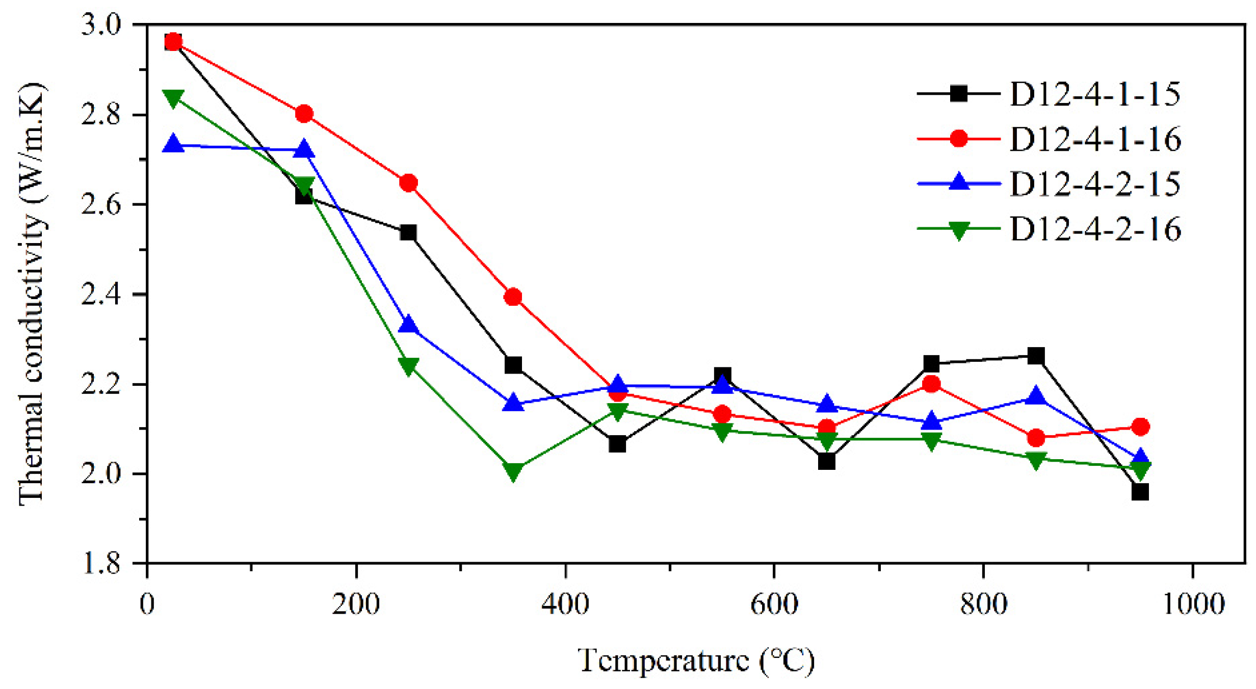
2.1. Temperature Dependency of Rock Thermal Parameters

The thermal conductivity, specific heat capacity and thermal expansion coefficient are the primary thermal parameters of rocks [28,29,30,31]. In this study, sandstone and siltstone samples collected from the strata adjacent to the 10# coal seam at Dacheng Coal Mine were used as experimental objects to investigate the variation of the parameters with temperature dependencies. The 10# coal seam is mainly located near the bottom of the Taiyuan Formation, with a depth of about 1330 m. It is a deep coal seam with a total thickness of 8 m. The coal seam gasification process can be divided into three stages: the heating stage, the temperature maintenance stage, and the cooling stage. Each stage has different temperature changing rates and holding times. Therefore, referring to the stage characteristics of temperature changes in this process, laboratory tests were conducted to examine the temperature-dependent variations of the rock samples’ thermal parameters.
In the experiment, a HotDisk-2500S thermal conductivity and specific heat capacity measuring instrument and a DIL402C thermal expansion coefficient measuring instrument were used. During the experimental process, the prepared rock samples were first heated to the set temperature and then allowed to cool to room temperature before being placed into the measuring instruments for testing. The specific test results are shown in Figure 1, Figure 2 and Figure 3.
The experimental results indicate that the thermal conductivity and specific heat capacity of the coal seam roof rocks decrease with increasing temperature. In the temperature range of 25 °C to 350 °C, the thermal conductivity exhibits a linear decreasing trend with temperature, with a reduction of approximately 0.2 W/m·K for every 100 °C increase in temperature. After reaching 350 °C, the thermal conductivity tends to stabilize and decreases slowly, with a reduction of around 0.02 W/m·K for every 100 °C increase in temperature, as shown in Figure 1.
Similarly, the specific heat capacity shows a linear decreasing trend with temperature in the temperature range of 25 °C to 650 °C, with a decrease of approximately 0.083 MJ/m3·K for every 100 °C increase in temperature. After reaching 650 °C, the specific heat capacity stabilizes within the range of 0.373 MJ/m3·K to 0.400 MJ/m3·K, as shown in Figure 2.
Furthermore, the thermal expansion coefficient of the rock samples exhibits an initial increase followed by a decrease with increasing temperature. Specifically, the thermal expansion coefficient of the roof rock mass shows a roughly linear increasing trend when the temperature rises from an initial temperature of 100 °C to 600 °C (from 12% to 83%), reaching its maximum value at temperatures of 600 °C. However, the thermal expansion coefficient of the roof rocks gradually linearly decreases with increasing temperatures above 600 °C, as shown in Figure 3.

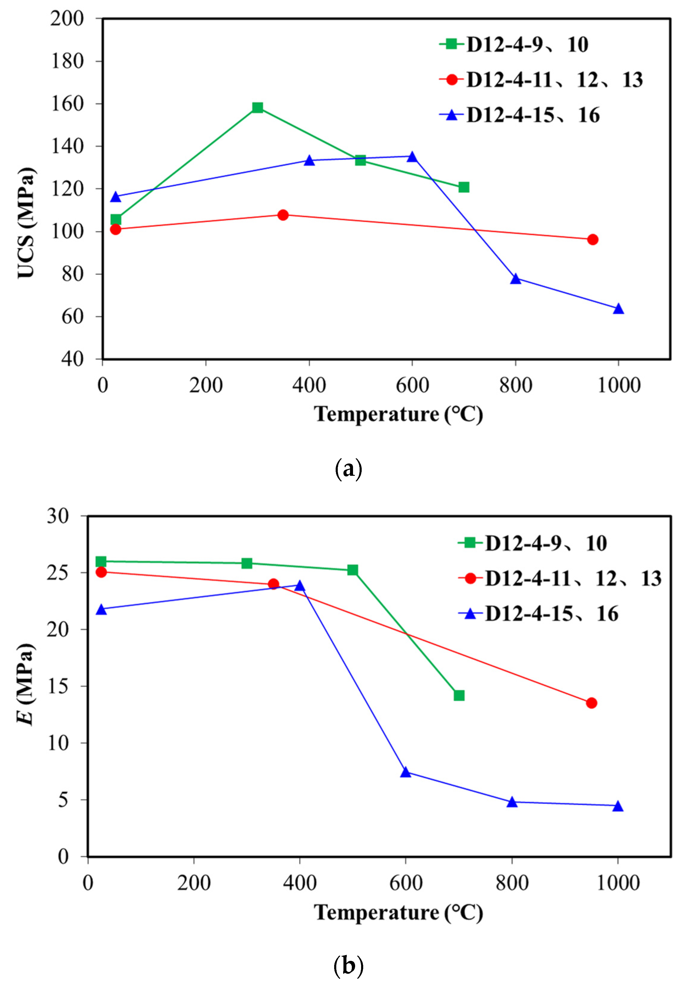
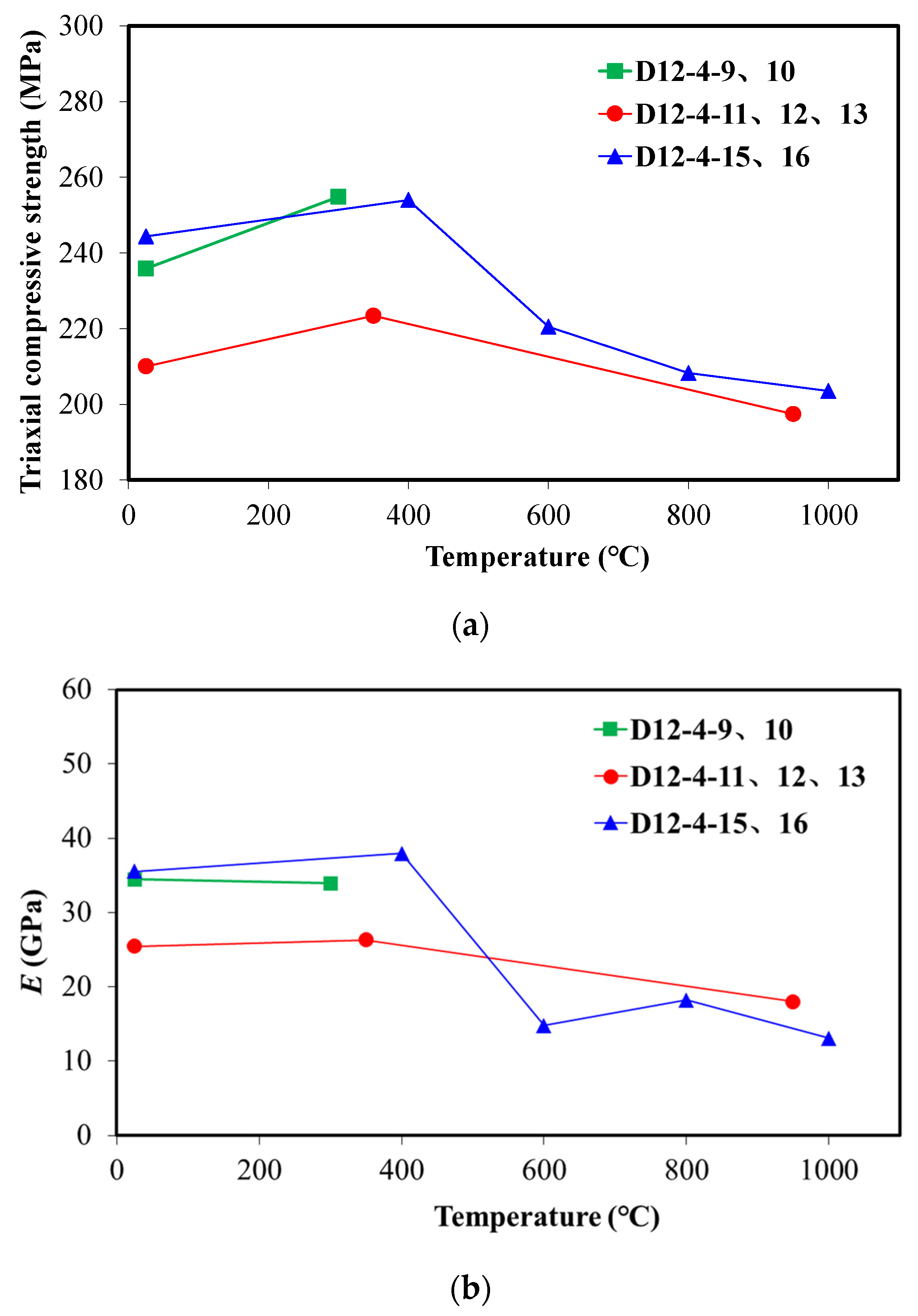
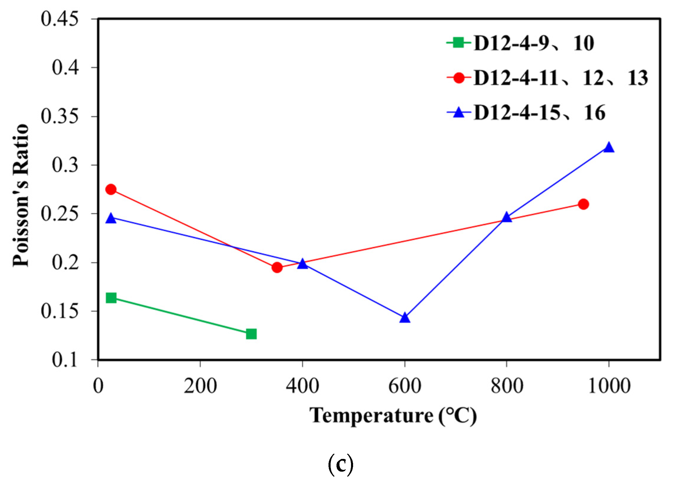
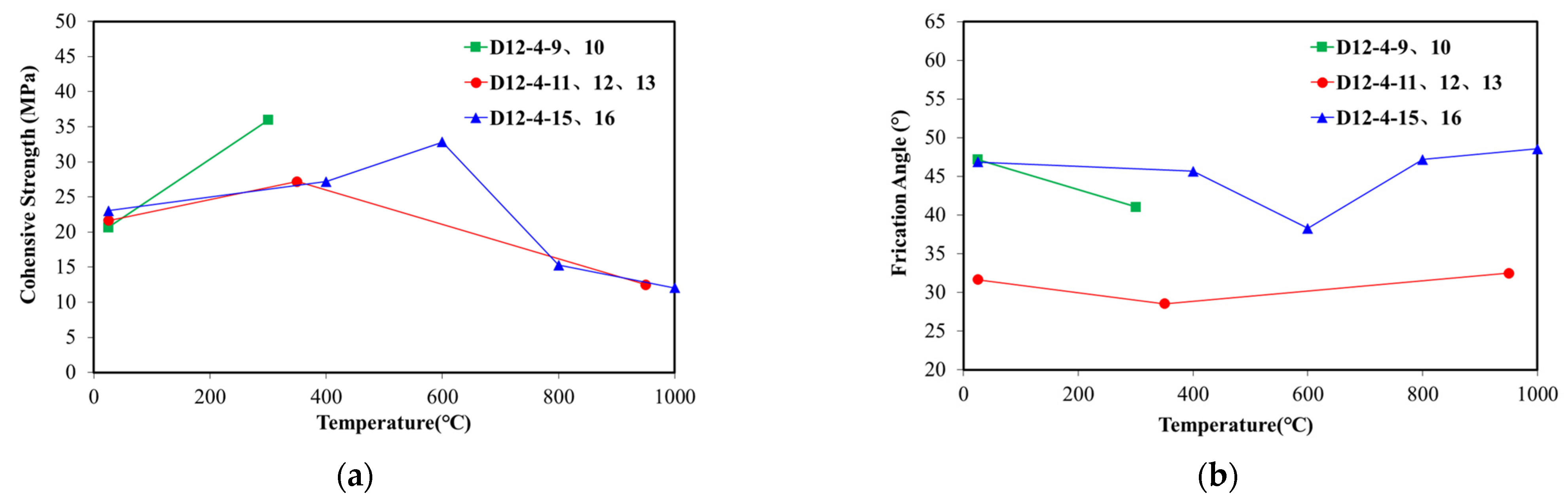
2.2. Temperature Dependency of Rock Mechanical Parameters

The influence of temperature on the mechanical properties of rocks is significant and manifested through the variation of constitutive model parameters and strength with temperature [32,33,34,35,36,37]. The variations of the parameters of sandstone samples under the temperature conditions during coal seam gasification were obtained by conducting uniaxial and triaxial mechanical laboratory experiments. The mechanical experiments were conducted with a TAW-1000 electrohydraulic servo-controlled rock mechanics testing system. During the experimental process, the prepared rock samples were first heated to the set temperature and then allowed to cool to room temperature before being placed into the triaxial apparatus for testing.
The test results of the uniaxial and triaxial mechanical parameters of the sandstone rock samples from the coal seam roof under different temperatures are presented in Figure 4 and Figure 5. Additionally, the cohesion and the angle of internal friction of the sample under different temperature conditions can be calculated utilizing the results of the triaxial tests. The analysis of these parameters is illustrated in Figure 6.
The test results for the sandstone samples from the target test area of the coal seam roof strata indicate a significant temperature effect on the rock mechanical properties in this region. The elastic modulus and the compressive strength of the roof sandstone remain relatively stable with increasing temperature below the critical temperature ranging from approximately 400 to 600 °C. However, once the temperature reaches the critical temperature, both of these measures significantly decrease as the temperature continues to rise. There are reductions of 50–80% in the elastic modulus and the compressive strength after the temperature reaches 1000 °C. The Poisson’s ratio exhibits a different trend compared with the previous two parameters. Below the critical temperature, the Poisson’s ratio decreases with increasing temperature and reaches its lowest value within the critical temperature range, a reduction of up to 50%. The Poisson’s ratio gradually increases with increasing temperature beyond the critical temperature and returns to its initial value at around 1000 °C. Additionally, it is observed that the internal friction angle shows little dependency on temperature, whereas the cohesion gradually increases below the critical temperature and rapidly decreases with increasing temperature above the critical range, with a maximum reduction of over 50%.
By integrating the obtained thermal and mechanical parameters of the rock samples with temperature-dependent behavior into the numerical simulation research process, a more realistic representation of underground construction conditions can be achieved, leading to more reliable simulation results.

3. Fundamentals of Mathematical Description and Geometrical Definition

Understanding the behavior of the rock mass under various conditions is crucial for ensuring the safe and sustainable operation of underground coal gasification. A two-dimension thermo-mechanical coupling model considering the panel orientations and the properties of rock mass with temperature dependences is established in this section to evaluate the stability of the surrounding formations by simulating the gasification process and describing the evolution of the stress field.

3.1. Governing Equations and Assumptions

Temperature plays a crucial role in ensuring continuous and stable production during underground coal gasification. The temperature field variations in the gasifier are influenced by factors such as the gasification agent, gasification modes and changes in the cavity [8,38,39,40,41]. Therefore, it is necessary to explore the evolution of the temperature field during the gasification process before investigating the mechanical integrity of the rock mass surrounding the gasification chamber, especially in determining the range of temperature field diffusion. The heat transfer process during gasification is simulated based on the fundamental theory of thermal conduction and certain assumptions.
The thermal energy transfer in the underground coal seam gasification process primarily occurs through thermal conduction. The spatial distribution of temperature over time can be described as follows:
c ρ T t x ( k T x ) y ( k T y ) = f ( x , y , t )
where ρ is the density of rock mass, m3/kg; c is the specific heat capacity, MJ/(m3·K); and k is the thermal conductivity, W/(m·k).
Based on the initial temperature conditions of the geological strata, the initial conditions of the target coal seam can be determined, which are as follows:
T ( x , y , 0 ) = φ ( x , y )
Furthermore, referring to the initial temperature distribution within the studied system, the temperature distribution and exchange laws between the system boundaries and the surrounding environment are investigated to determine the first and second type boundary conditions, which can be expressed as follows:
T ( x , y , t ) | Ω × ( 0 , + ) = g ( x , y , t )
k T n | Ω × ( 0 , + ) = g ( x , y , t )
The third type of boundary condition refers to the linear relationship between the temperature on the boundary of the thermal conduction system and its derivative on the boundary. It is used to describe the heat exchange between the edges of the thermal conduction system and the surrounding external environment and can be represented as follows:
( T n + α T ) | Ω × ( 0 , + ) = g ( x , y , t )
The temperature difference in the surrounding rock mass of coal seams caused by the various properties of each stratum leads to the generation of thermal expansion stress. The constitutive equation of the rock mass with high temperature during the gasification process is as follows:
{ ε x = 1 E [ σ x v ( σ y + σ z ) ] + α T T ε y = 1 E [ σ y v ( σ z + σ x ) ] + α T T γ x y = 2 ( 1   +   v ) E τ x y
where ε x ,   ε y ,   γ x y are strains; σ x ,   σ y ,   σ z ,   τ x y are stresses, Pa; E is the elastic modulus, Pa; v is the Poisson’s ratio; and α T is coefficient of linear thermal expansion, K−1.
By introducing the shear modulus G, Pa, the Lamé constant λ, Pa, the volumetric strain e and the thermal stress coefficient β, K−1, Equation (7) can be transformed as:
{ σ x = 2 G ε x + λ e β T σ y = 2 G ε y + λ e β T σ z = λ e β T τ x y = G γ x y
where the expressions of the various quantities are:
G = E 2 ( 1 + v )
λ = E v ( 1 + v ) ( 1 2 v )
e = ε x + ε y
β = α T E 1 2 v
in which β is thermal stress coefficient, Pa/K and e is volumetric strain.
By introducing the equilibrium differential equation, Equation (8), and substituting the thermal stress into it, the equilibrium differential equation for the thermal stress problem can be obtained, as in Equation (9):
{ σ x x + τ y x y + X = 0 σ y y + τ x y x + Y = 0
{ λ + G e x + G 2 u β T x + X = 0 λ + G e y + G 2 v β T y + Y = 0
Based on the description of the heat exchange process and mechanical behavior mentioned above, a two-dimensional thermo-mechanical coupling model for the surrounding rocks of the gasification cavity in the coal seam is established by considering the temperature of the geological formation, stratification of the formation, thermal properties of the rocks and characteristics of the coal seam gasification process in the studied area.
For the thermo-mechanical coupling model of surrounding rock in underground coal gasification, the following assumptions are introduced:
(a)
The surrounding rocks are isotropic with no cracks or faults;
(b)
There are no other sources of heat apart from the heat generated during the underground coal gasification process due to the original temperature of the formation;
(c)
The heat transfer within the system is primarily governed by thermal conduction, neglecting factors such as convection or radiation, and the pressure inside the gasification chamber remains uniform at all times;
(d)
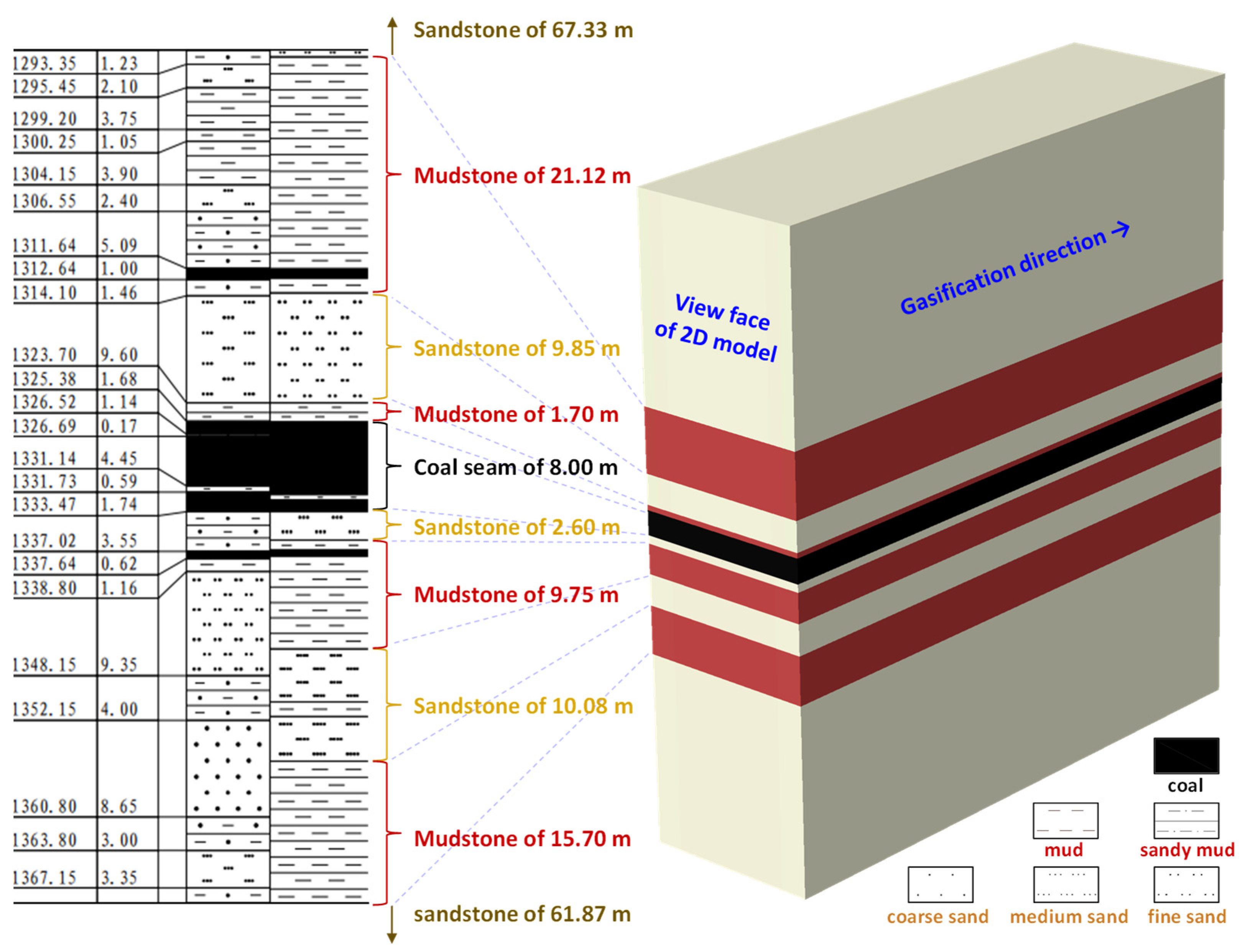
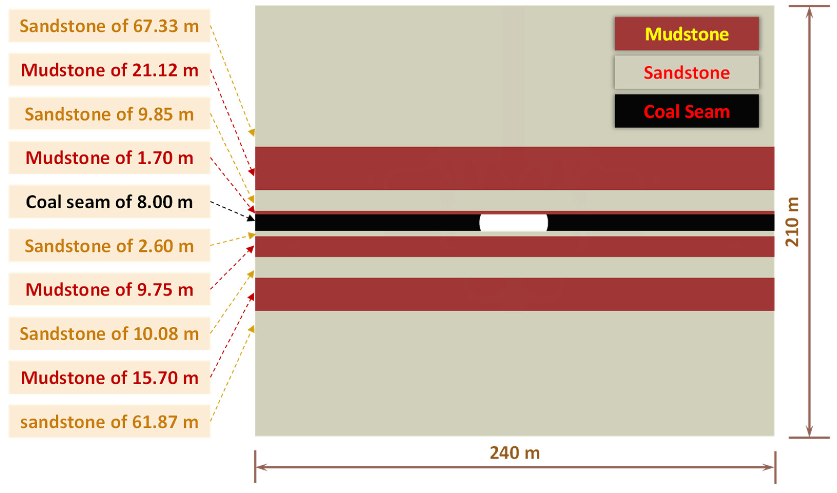
The geological model is simplified as a two-dimensional plane strain model during the gasification process; the initial geometric shape of the gasification chamber is approximated as a cuboid.

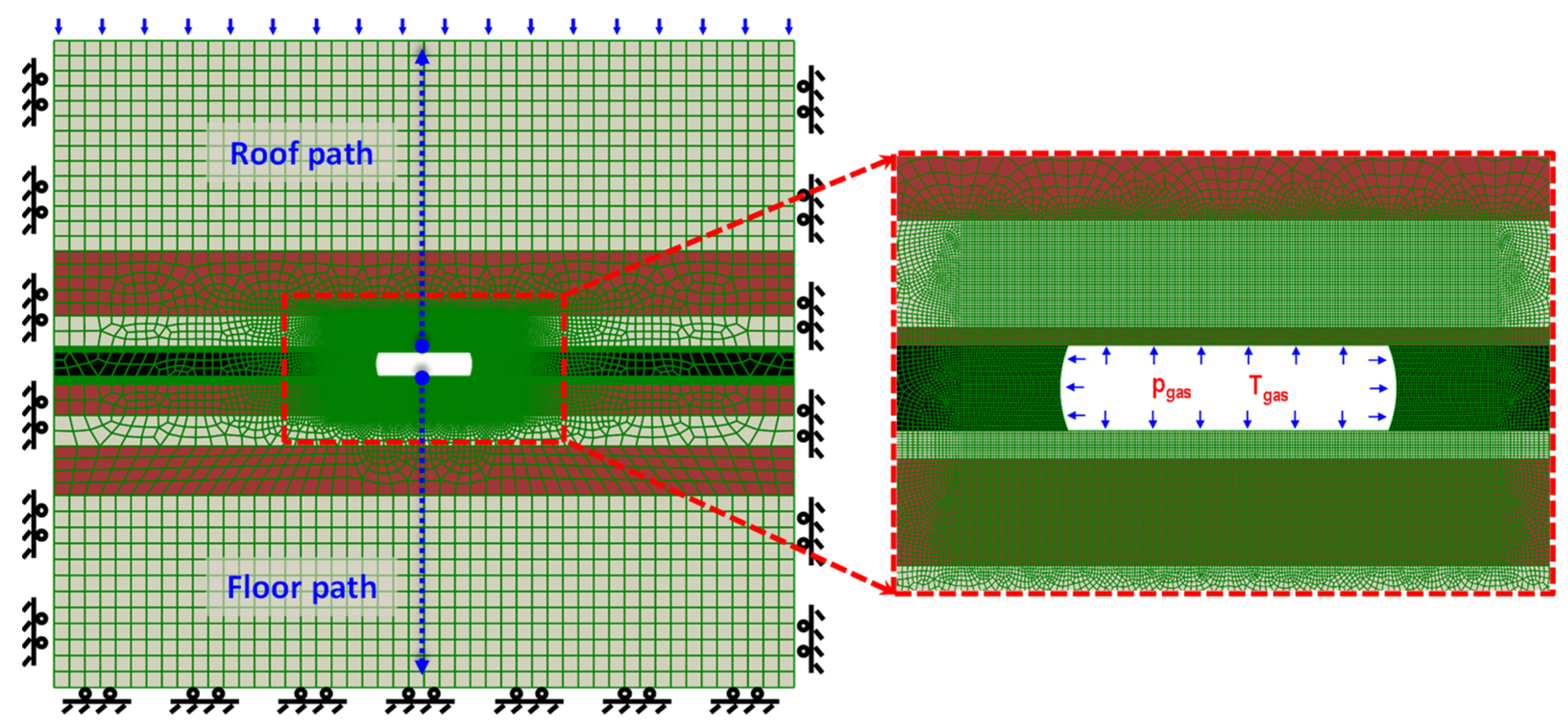
3.2. Geometry Model of the Finite Element Method Simulation
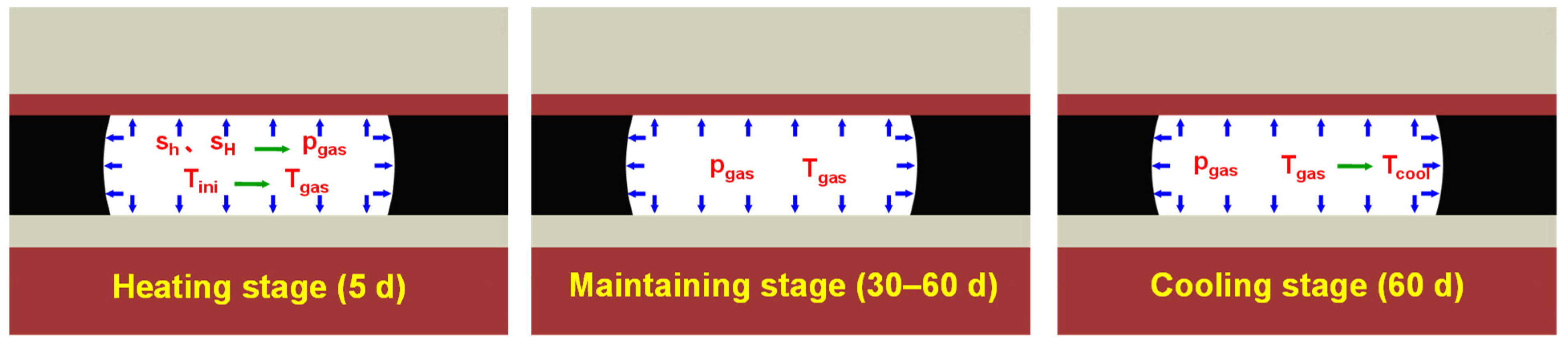
The target of coal seam gasification construction was selected as the main coal seam at the bottom of the Taiyuan Formation in the Dacheng Coal Mine. The roof and floor lithology of the coal seam mainly consist of thick sandstone layers and relatively thin mudstone layers, with numerous small interlayers within the main coal seam. Referring to the stratigraphic information revealed by logging, the thinner layers and small interlayers are simplified and merged, resulting in the stratification within a range of 100 m above and below the coal seam in the model, as shown in Figure 7. This simplification facilitates the subsequent analysis and computation of the model.
Based on the stratification of the formation and the range of the gasification chamber width (10–60 m), a two-dimensional geometric model with a width of 240 m and a thickness of 210 m was established, as shown in Figure 8. This ensures that the model captures the significant temperature variations and diffusion characteristics during the gasification process. Two gasification panel directions were considered along the maximum horizontal stress direction and the minimum horizontal stress direction stress (as presented in Figure 9) for thermo-mechanical coupling simulation and comparison of the stress field evolution.
The lithology and thickness of the roof and floor strata of the combustion zone are shown in Figure 8. Considering the need for high precision in stress field evolution simulation and failure analysis, the mesh around the gasification cavity is refined (0.25 m) and gradually transitions to a coarser mesh (5.0 m) in the boundary. The plane strain quadratic interpolation thermo-mechanical coupling analysis element (CPE8T) was used for meshing. Normal displacement constraints are applied to the left and right sides of the model and the bottom surface. The overburden stress corresponding to the depth was applied to the top surface of the model The internal model was subject to the geostatic stress, as presented in Figure 9. Temperature and pressure boundary conditions were applied to the inner surface of the cavity at different stages, as shown in Figure 10.
The geometric shape of the gasification chamber is complex and worth investigating [42,43]. However, the integrity of the roof and floor strata of the combustion cavity are focused on more than the pillars in this study. The geometric shape of the sidewalls is therefore not emphasized.
Additionally, the model was set with an in situ temperature of 44 °C and an operating temperature of 1200 °C on the chamber walls during the coal seam gasification process. The operating temperature was maintained for 45 days, after which the chamber walls were cooled to a temperature of 200 °C. As the lithology of the roof and floor differs, the thermal properties of the sandstone layer can be referenced from the aforementioned experimental test results for sandstone roof strata. The thermal and mechanical properties of mudstone from previous research are adopted as a reference [44,45,46].
The thermo-mechanical model was established considering two scenarios for gasification panels along the directions of the maximum and minimum horizontal stresses. Typical gasification conditions were set with a panel width of 25 m, a constant gasification temperature of 1200 °C for 45 days and an equivalent density of gasification operating pressure of 0.3 g/cm3. The effects of temperature on properties of surrounding rock mass were also considered.
The thermal coupling simulation process was conducted in three stages during the gasification process, as shown in Figure 11:
(a)
Gasification heating stage (5 days): The supporting load of the chamber internal wall was reduced from the initial in situ stress to the gasification operating pressure pgas and the chamber wall surface temperature was raised to the gasification operating temperature Tgas;
(b)
Temperature maintaining stage (30–60 days): The supporting load of the chamber internal wall maintained the gasification operating pressure pgas, and the chamber internal surface temperature maintained the gasification operating temperature Tgas;
(c)
Cavity cooling stage (60 days): The supporting load of the chamber internal wall maintained the gasification operating pressure pgas, and the chamber wall surface temperature was reduced to the gasification cooling temperature Tcool.
The thermo-mechanical coupled model was implemented with the finite element software ABAQUS 2022 using its coupled temperature–displacement capability. The temperature-dependent thermal and mechanical properties gained from the experiments were incorporated into the simulations through a subroutine (UFIELD) coded in Fortran. The stress distributions were generated directly from the analysis, whereas the damage distributions are represented with the equivalent plastic strain (PEEQ).

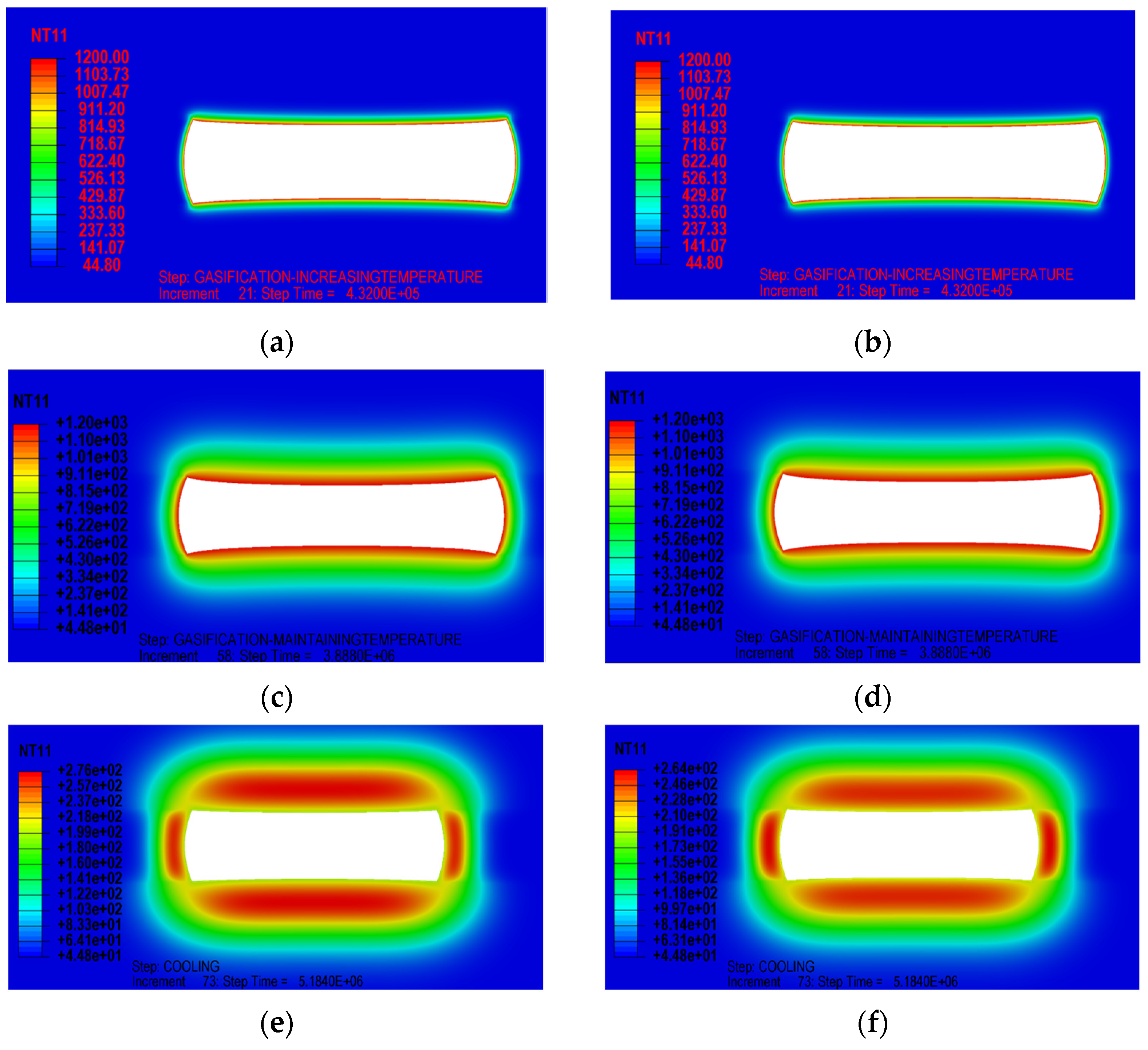
4. Evolution of the Stress and Temperature Field near the Gasification Chamber

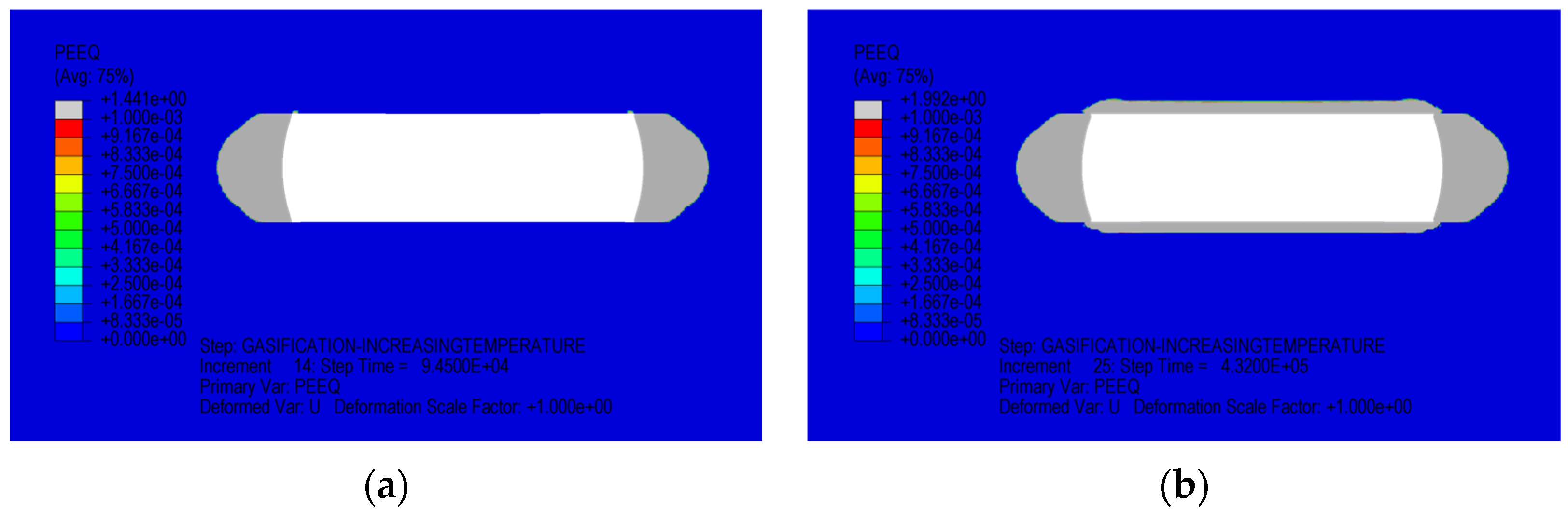
4.1. Stress State and Failure Risk in the Vicinity of the Gasification Chamber

The evolution of the stress and temperature field near the gasification chamber is described with the panel along the largest and the smallest horizontal stress. The initial stress states in the two different situations are shown in Figure 12 and Figure 13, where S22 represents the overburden stress and S11 and S22 represent the principal horizontal stresses.
The tensile strength of rock mass is much lower than their compressive strength, which means that rocks are at great risk of tensile failure under tensile stress. When the gasification chamber is burned out, the chamber walls lose support from the roof and floor strata. Moreover, the support force is reduced to the gasification pressure of 3.99 MPa (at a depth of 1330 m, with equivalent density of 0.3 g/cm3) in the cavity. The roof and floor strata bend and deform towards the inside of the cavity with additional tensile stress generated on the surface of the roof and floor strata. If the tensile stress is higher than the original horizontal compressive stress, the roof and floor strata are in a tensile stress state and may undergo tensile failure.
A vertical upward path for obtaining data was set at the middle of the roof to visually observe the stress state of the roof (see Figure 10). From the calculation results, the original horizontal compressive stress was relatively low when the gasification panel was arranged along the direction of the largest horizontal stress. With bending and subsidence, the surface of the roof strata was in a tensile stress state. The deformation results of the roof and floor strata in Figure 14 show that the roof strata of the gasification chamber subsided by 5.39 cm in the middle, whereas the floor strata uplifted by 3.58 cm, which may lead to tensile fracture. However, when the gasification panel was arranged along the direction of the smallest horizontal stress, the situation was improved. The results in Figure 15 show that the stress state was compressive stress and the risk of tensile failure was significantly reduced.

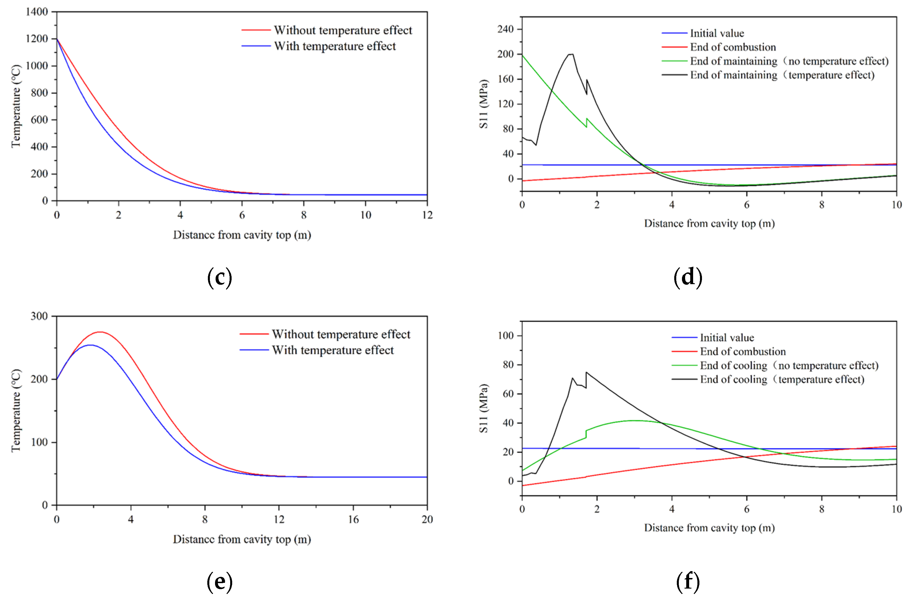
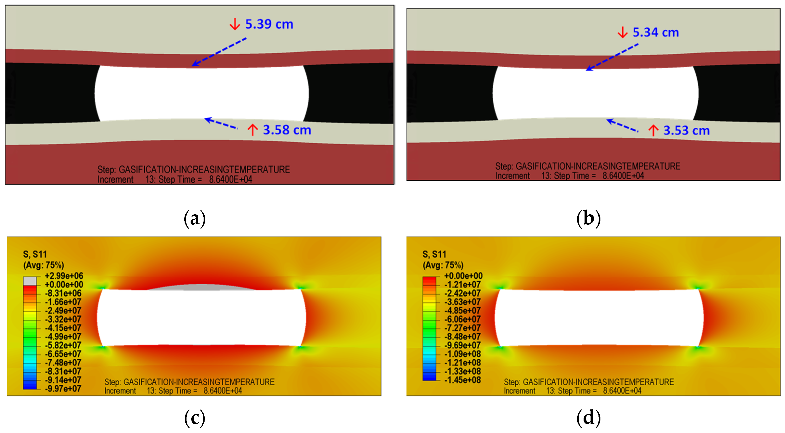
4.2. Influence of Temperature Dependency on Stress State during the Gasification Process

The temperature dependency of the thermal and mechanical properties of rock was considered in the simulation of the evolution of the temperature and stress field in the gasification chamber. To verify the specific influence of temperature effects on the roof and floor strata, a comparative analysis of whether to concern temperature effect was carried out in the three stages of gasification. The distribution of temperature and stress in Figure 16 and Figure 17 shows that the temperature effect has different influences on the diffusion of the temperature field and the distribution of the stress field. The obtained data in Figure 18 are still along the vertical upward path in the middle of the roof.
Due to the relatively short duration of the 5-day gasification heating stage, the temperature diffusion range was just 1.5 m. However, during the 45-day temperature maintaining stage, the temperature diffusion zone of the rock surrounding the gasification cavity gradually expanded. During the cooling stage, the temperature diffusion zone still expanded because the heated region still had a higher temperature than the rock further away. Therefore, the diffusion process of the temperature field continued to occur. It can be observed from Figure 18 that the temperature effect had a minimal impact on the temperature field. The thermal conductivity of the rock decreases when considering the temperature effect, resulting in a slower diffusion of the temperature field during a temperature increase or decrease. Additionally, due to the reduction in the specific heat capacity when considering the temperature effect, the temperature field during the cooling stage was also lower than considering temperature effect.
The highest stress level occurred during the heating stage, where there was a large temperature difference in the surrounding rock mass of the gasification chamber. As a result, the stress concentration was pronounced near the gasification cavity wall, where the stress may reach above 240 MPa. At this moment, the rock may experience potential failure and start to collapse. During the temperature maintaining stage, the stress concentration gradually alleviated with the diffusion of the temperature field but remained at a relatively high level. The damage region may expand at this stage. After the 60-day cooling gasification stage, the horizontal thermal stress near the roof decreased, whereas the temperature diffusion zone gradually expanded. With the further diffusion of high-temperature stress (S11, S33) to the inside of the roof, the range of the compression damage of roof strata continued to expand. The temperature dependency’s effect on the stress field was not as significant as predicted. The stress levels are nearly the same before the cooling stage, whereas the positions of stress concentration are slightly shifted due to the different temperature dependencies of thermal property between layers. However, the stress field considering the temperature effect is higher at the end of the cooling stage. This is because the temperature field cools down more slowly and the thermal stress is not completely released in time.

5. Evolution of Stress and Temperature Field near the Gasification Chamber

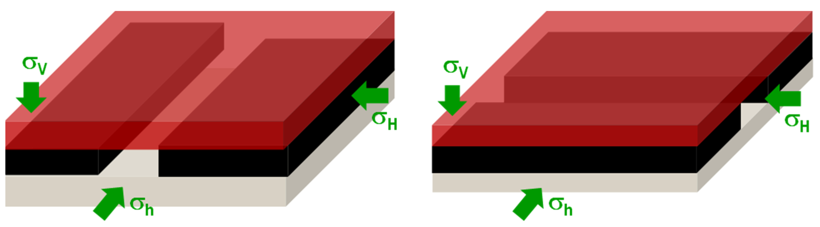
5.1. Influence of Panel Orientation on Vicinity Stability during the Gasification Process

In the design of UCG operations, the orientation of panels is a crucial factor that needs to be considered emphatically. The orientation of the gasification panels plays a significant role in determining the stress distribution and potential failure mechanisms within the rock mass. In conventional oil and gas extraction processes, the wellbore orientation is determined by considerations related to reservoir development, as well as the feasibility of drilling and subsequent stimulation such as hydraulic fracturing. Selecting the appropriate channel orientation involves considering factors such as the stress concentration, effective gasification area and potential for strata instability. Furthermore, it is important to consider the temperature dependency of the rock mass and its impact on channels with different orientations.
To simulate the typical conditions of the gasification process, the gasification chamber width was set as 25 m and a constant gasification temperature of 1200 °C was assumed with a gasification duration of 45 days under a pressure equivalent density of 0.3 g/cm3. In the model, the Mohr–Coulomb strength criterion considering the temperature dependence is used to describe the shear failure of the surrounding rock. These conditions provide a representative basis for analyzing the potential failure mechanisms in the surrounding rock mass of the gasification chamber.
The results in Figure 19 illustrate the evolution process of rock failure in the vicinity of a typical gasification chamber. During the heating stage, the roof strata show initial signs of noticeable damage, with a range of nearly 1 m in the roof and floor strata. However, the area of the failure zone is not extensive due to the relatively short duration. As the maintaining stage progresses, the damage zone gradually expands, with a range of nearly 3–4 m in the roof and floor strata. By the end of the cooling stage, the damage zone spreads to a larger range of more than 6 m towards the floor strata. Therefore, the deformation characteristics of the roof and floor strata during the maintaining and cooling stages were investigated, as depicted in Figure 20. Two predefined paths are utilized to collect data on the equivalent plastic strain (PEEQ). One path followed a vertical upward direction along the middle of the roof, as previously mentioned. The other path correspondingly followed a vertical downward direction along the midsection of the floor. The potential degradation of materials due to temperature dependency was also simultaneously taken into consideration.
By comparison, it can be observed that the orientation of the gasification chamber along the direction of the smallest or largest horizontal stress had a relatively minor influence on the range of damage to the roof and floor strata. The reason for this is that the damage to the roof and floor strata during the gasification process is primarily caused by compressive/shear failure induced by thermal stresses. The differences in the original horizontal stresses with different orientations of the gasification chamber are relatively small compared with the thermal stresses generated at high temperatures. The mechanical and thermal properties of the roof and floor strata have a relatively small impact on the range of damage to the strata. However, they have a significant influence on the degree of rock damage within the damage zone. This is because the mechanical properties of the rock need to surpass a certain critical temperature (500–600 °C) to undergo changes, whereas the thermal stresses generated when the temperature reaches the critical threshold are sufficient to cause damage to the roof and floor strata. During each gasification cycle and subsequent gasification processes, although the temperature of the roof and floor strata decreases, the influence zone of high temperatures within the strata continues to expand. Therefore, during this stage, the range of the damage zone will continue to enlarge despite the decreasing temperatures of the roof and floor strata.

5.2. Variation of Damage Zone in Surrounding Rock of the Combustion Chamber

In order to explore the influence of various factors on the damage characteristics in the surrounding rock of the combustion chamber, numerical simulations were conducted under different variable conditions. These conditions included variations in the gasification chamber width, temperature maintaining duration of the gasification reactor, gasification operating temperature and gasification operating pressure equivalent density. Thus, the simulations were carried out based on typical gasification parameters: gasification chamber width (10 m, 15 m, 20 m, 25 m, 30 m, 40 m, 60 m), temperature maintaining duration (30 days, 35 days, 40 days, 45 days, 50 days, 55 days, 60 days), gasification operating pressure equivalent density (0.1 g/cm3, 0.2 g/cm3, 0.3 g/cm3, 0.4 g/cm3, 0.5 g/cm3) and gasification constant temperature operating temperature (900 °C, 1000 °C, 1100 °C, 1200 °C, 1300 °C, 1400 °C). The distribution maps of equivalent plastic strain obtained from numerical simulations provide a visual representation of the influence of various factors on the size of the damage zone. However, to compare the range and severity of the damage zone under different conditions, the two created vertical paths previously mentioned along the middle of the roof and floor strata need to be utilized.

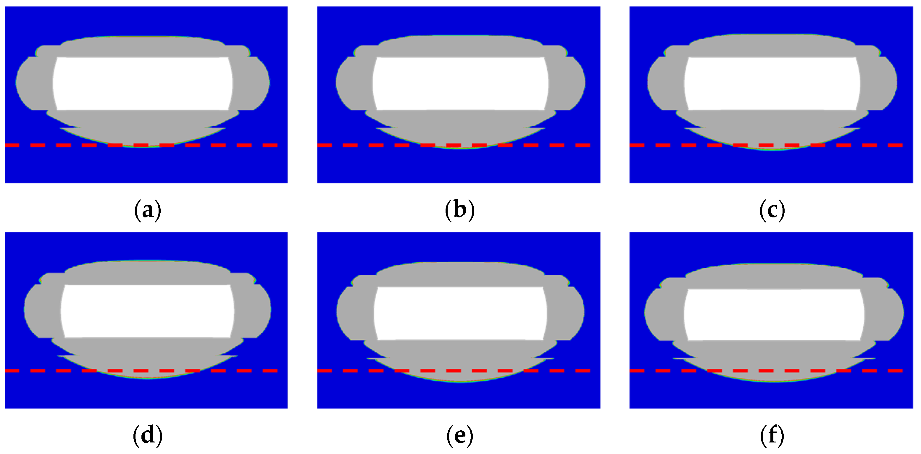
5.2.1. Influence of Gasification Chamber Width

The influence of different gasification chamber widths on the range of the damage zone is relatively minor, as observed in Figure 21. However, the comparison in Figure 22 indicates that the range of the damage zone is significantly smaller when the gasification chamber width is 10 m. The discrepancy can be attributed to the fact that the gray area in Figure 21 is defined as PEEQ > 0.001, which corresponds to the observation criteria for conventional sanding issues. Regarding the severity of the damage, it is observed that a smaller gasification chamber width leads to a more severe level of damage within a distance of 2 to 3 m from the floor strata. It should be noted that within a range of 2.6 m beneath the coal seam floor exists sandstone, whereas within a range of 1.7 m above the coal seam floor exists mudstone. It can be inferred from Figure 22 that the mudstone roof and floor strata exhibit a higher sensitivity to the gasification chamber width.
The width of the damage zone in the roof and floor strata increases with the increasing width of the chamber. The thickness of the damage zone in the roof and floor slightly increases with the increase in the chamber width. As the chamber width increases from 10 m to 60 m, the thickness of the roof damage zone increases from 3.1 m to 3.6 m and the thickness of the floor damage zone increases from 4.0 m to 6.2 m; however, the increase is not significant. This is mainly due to the dominant influence of thermal expansion stress on the damage in the roof and floor strata of the gasification chamber, whereas the stress distribution resulting from dimensional changes in the chamber has a minor impact on the damage zone in the roof and floor strata.

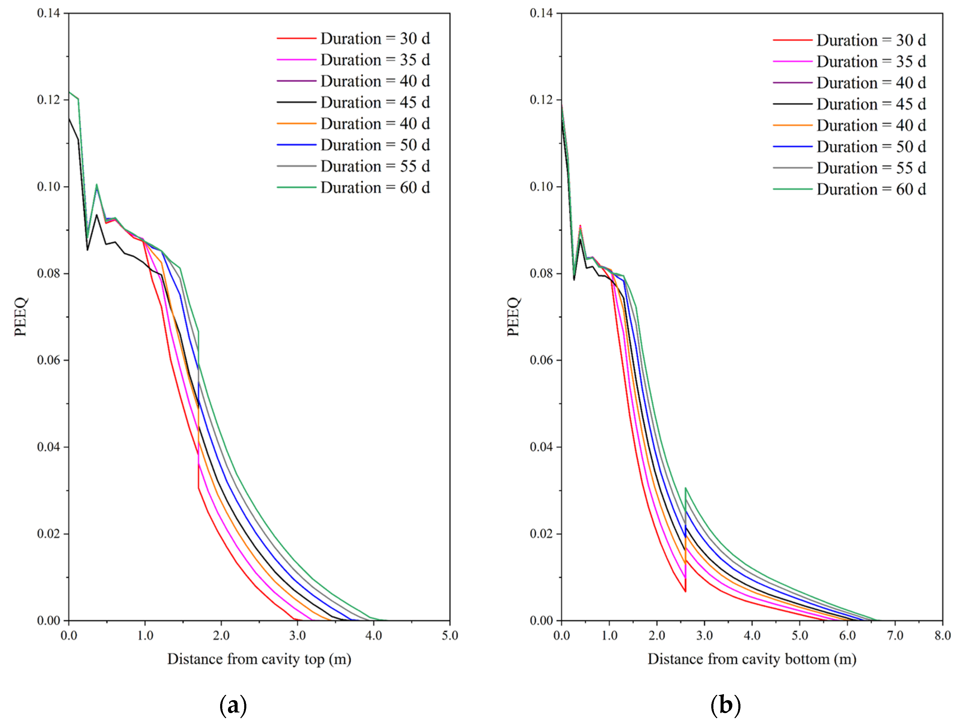
5.2.2. Influence of Temperature Maintaining Duration

Due to the prolonged duration of the maintaining temperature stage, most of the damage behavior and the spreading of the damage zone occur during this stage. Therefore, a simulation study was conducted specifically for the duration of this stage. The results indicate that the longer the duration of the maintaining temperature stage, the larger the diffusion range of the damage zone. As the duration of the gasification at a constant temperature increases from 30 days to 60 days, the thickness of the roof strata damage zone increases from 3.1 m to 4.2 m and the thickness of the floor strata damage zone increases from 5.6 m to 6.6 m, as shown in Figure 23. However, the impact of maintaining the temperature duration on the range of damage to the roof and floor strata is not significant. The influence is more pronounced on the roof strata than on the floor strata according to Figure 24.

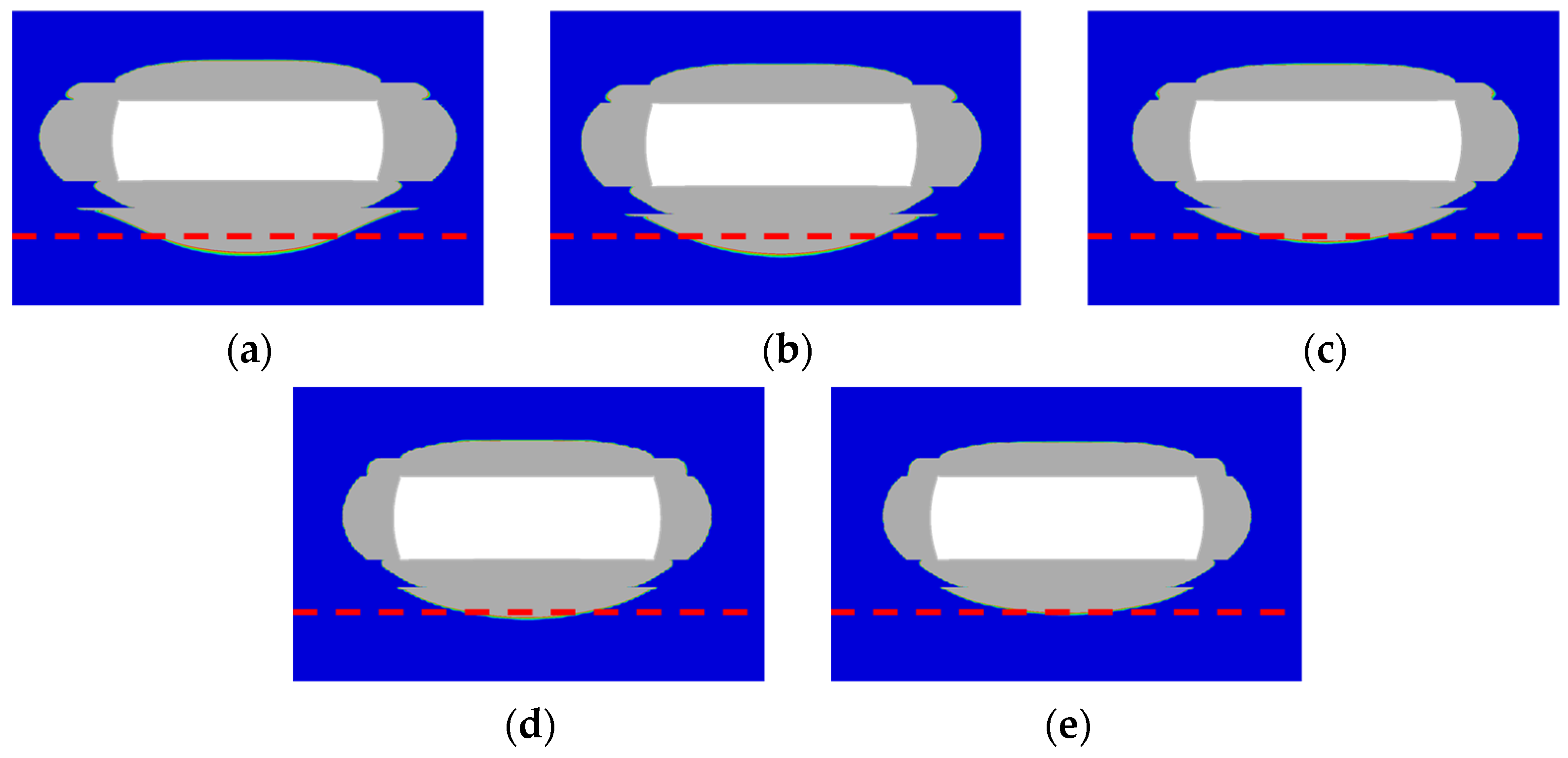
5.2.3. Influence of Gasification Operating Temperature

Different gasification operating temperatures not only influence the temperature field around the gasification chamber, leading to thermal stress, but also alter the thermal and mechanical material properties of the surrounding rock mass. Under the combined influence, the gasification operating temperature has the greatest impact on the degree of damage among the considered factors. However, it does not imply that the gasification operating temperature has a greater effect on the size of the damage zone, as shown in Figure 25. According to the results for 4 m in Figure 26, it can be observed that the thickness of the roof and floor strata damage zone increases with the increase in the operating temperature during the maintaining temperature stage. As the operating temperature increases from 900 °C to 1400 °C, the thickness of the top plate damage zone increases from 3.2 m to 3.9 m and the thickness of the floor strata damage zone increases from 5.6 m to 6.4 m.

5.2.4. Influence of Gasification Operating Pressure

The magnitude of the gasification operating pressure directly affects the degree of damage in the damage zone. The gasification operating pressure directly acts on the surrounding rock mass by exerting support on the internal wall of the gasification chamber during the gasification process after combustion. Therefore, the range of the damage zone decreases as the gasification operating pressure increases, as shown in Figure 27. According to the results in Figure 28, it can be observed that the regions in close proximity to the internal wall of the gasification chamber are most affected by the operating pressure. The gasification pressure equivalent density is used here to represent the gasification operating pressure. The influence of gasification pressure is more significant on the floor strata than on the roof strata. As the gasification pressure equivalent density increases from 0.1 g/cm3 to 0.5 g/cm3, the thickness of the roof strata damage zone decreases from 4.0 m to 3.3 m, whereas the thickness of the floor strata damage zone decreases from 7.9 m to 5.3 m.

6. Discussions

In this paper, the distributions of temperature, stress and damage in the vicinity of the surrounding rocks of the UCG cavity have been investigated through thermo-mechanical coupled numerical simulations. The temperature dependency of the thermal and mechanical properties of surrounding rocks were experimentally tested and considered in the analysis. The effects of gasification panel orientation and gasification chamber size, as well as gasification operation parameters on the stress and damage distributions were also quantified. The experimental and numerical results offer valuable data and understanding for the design and assessment of future UCG projects. For example, once the distance between the aquifer and the target coal seam is given, then the risk of underground water contamination can be evaluated and the operation parameters can be optimized to reduce the risk.
Despite the findings presented, the work in this paper still leaves a few open questions unaddressed. One specific aspect is that even though the stress and damage distributions within the surrounding rocks can be predicted, the amount of rock mass that will collapse is still to be determined. Additionally, the critical size of the damage zone that should lead to a halt in the UCG operation remains unsolved. In addition, the sustained integrity of the rocks surrounding the gasification chamber in the long run during the UCG process still need to be investigated. All these questions justify further study, especially combined experimental/numerical and field studies.

7. Conclusions

This study aimed to investigate the thermo-mechanical behavior and integrity of the surrounding rock in the gasification vicinity to facilitate safe and efficient UCG operations. The study began with an experimental study of the temperature dependency on the thermal and mechanical properties for the Decheng Coal Mine. The findings are incorporated into a thermo-mechanical coupling model developed to analyze the stress and damage distribution near the gasification chamber. In addition, the effects of panel orientation, chamber width, maintaining duration, operating temperature and operating pressure on the failure behavior of the gasification surrounding rocks are illustrated through parametric analysis. The following conclusions and observations can be drawn:
  • The thermal conductivity exhibits a linear decreasing trend with temperature in the range of 25 °C to 350 °C and tends to stabilize and decreases slowly beyond 350 °C. The specific heat capacity shows a linear decreasing trend with temperature in the range of 25 °C to 650 °C and stabilizes after reaching 650 °C. The thermal expansion coefficient shows a roughly linear increasing trend when the temperature rises from 100 °C to 600 °C and decreases linearly with temperature after surpassing 600 °C;
  • The elastic modulus and the compressive strength remain relatively stable with increasing temperature below a critical temperature ranging from approximately 400 to 600 °C. However, once the temperature reaches the critical temperature, both measures significantly decrease as the temperature continues to rise. The Poisson’s ratio decreases with increasing temperature below the critical temperature, gradually increases with temperature beyond the critical temperature and can return to its initial value at around 1000 °C;
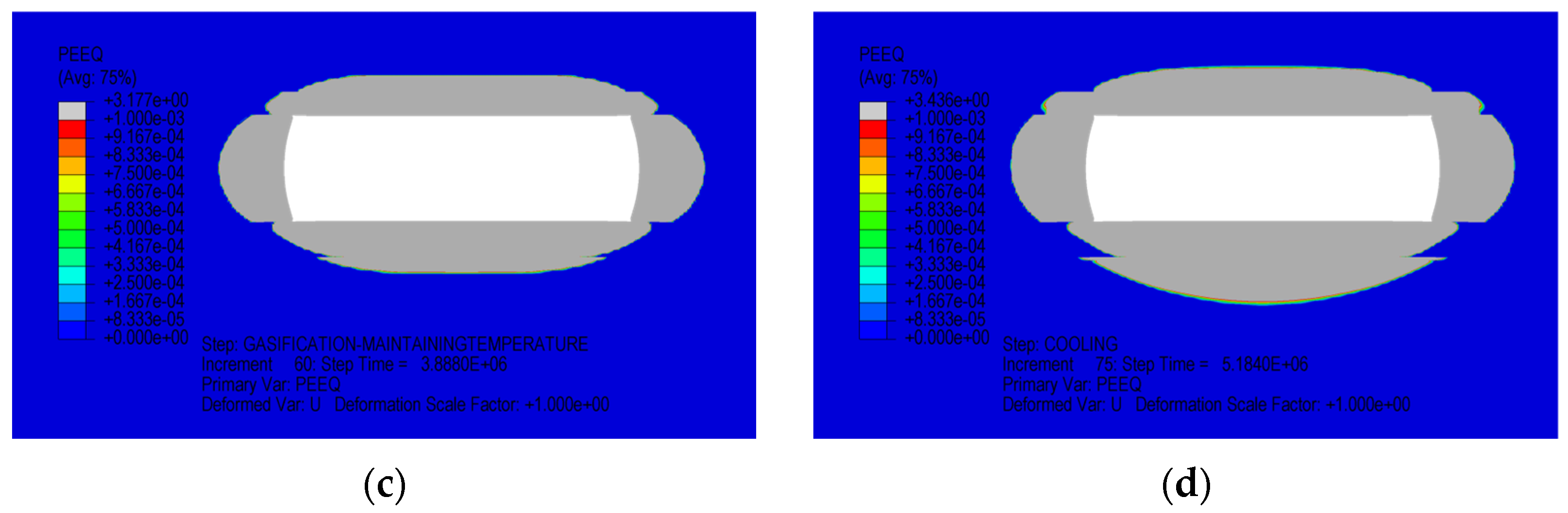
  • The roof strata show initial signs of noticeable damage during the heating stage, with a range of less than 1 m in the roof and floor strata. As the maintaining stage progresses, the damage zone gradually expands with a range of nearly 3–4 m in the roof and floor strata. By the end of the cooling stage, the damage zone spreads to a larger range of more than 6 m towards the floor strata;
  • The orientation of the gasification chamber has a relatively minor influence on the range of damage to the roof and floor strata. The width and thickness of the damage zone in the roof and floor strata increase when the width of the chamber is increased. The longer the duration of the maintaining temperature stage, the larger the diffusion range of the damage zone. The gasification operating temperature has the greatest impact on the degree of damage among the considered factors. The magnitude of the gasification operating pressure directly affects the degree of damage in the damage zone, and the influence is more significant on the floor strata than on the roof strata.
The findings have practical implications for the design and assessment of UCG processes, enhancing the safety and efficiency of coal gasification operations.

Author Contributions

Methodology, P.W. and W.L.; Formal analysis, P.W., Q.X., Q.L. and Y.Z.; Data curation, Q.X.; Writing—original draft, P.W.; Writing—review & editing, W.L.; Visualization, Y.H.; Supervision, J.D. and W.L.; Project administration, W.L. All authors have read and agreed to the published version of the manuscript.

Funding

This research was funded by Science Foundation of China University of Petroleum Bejing: No. ZX20200116.

Data Availability Statement

The data that support the findings of this study are available on request from the corresponding author. The data are not publicly available due to privacy restrictions.

Conflicts of Interest

The authors declare no conflict of interest.

References

  1. Couch, G.R. Underground Coal Gasification; Technical Report, CCC/151; IEA Clean Coal Centre: London, UK, 2009. [Google Scholar]
  2. Bhutto, A.W.; Bazmi, A.A.; Zahedi, G. Underground Coal Gasification: From Fundamentals to Applications. Prog. Energy Combust. Sci. 2013, 39, 189–214. [Google Scholar] [CrossRef]
  3. Burton, E.; Upadhye, R.; Friedmann, S. Best Practices in Underground Coal Gasification; Lawrence Livermore National Lab (LLNL): Livermore, CA, USA, 2017.
  4. Perkins, G. Underground Coal Gasification—Part I: Field Demonstrations and Process Performance. Prog. Energy Combust. Sci. 2018, 67, 158–187. [Google Scholar] [CrossRef]
  5. Feng, L.; Dong, M.; Wang, B.; Qin, B. Gas Production Performance of Underground Coal Gasification with Continuously Moving Injection: Effect of Direction and Speed. Fuel 2023, 347, 128425. [Google Scholar] [CrossRef]
  6. Feng, M.; Xin, L.; Wang, Z.; Li, K.; Wu, J.; Li, J.; Cheng, W.; Wang, B. Discussion on Requirements of Gasifier Gas Tightness for Underground Coal Gasification Production. Sustain. Energy Technol. Assess. 2021, 47, 101550. [Google Scholar] [CrossRef]
  7. Kačur, J.; Laciak, M.; Durdán, M.; Flegner, P.; Frančáková, R. A Review of Research on Advanced Control Methods for Underground Coal Gasification Processes. Energies 2023, 16, 3458. [Google Scholar] [CrossRef]
  8. Yu, L.; Liu, S.Q. Thoughts on Commercialization of the LLTS-UCG New Technique. Sci. Technol. Rev. 2003, 2, 51–53. [Google Scholar]
  9. Najafi, M.; Jalali, S.M.E.; KhaloKakaie, R. Thermal–Mechanical–Numerical Analysis of Stress Distribution in the Vicinity of Underground Coal Gasification (UCG) Panels. Int. J. Coal Geol. 2014, 134–135, 1–16. [Google Scholar] [CrossRef]
  10. Seifi, M.; Chen, Z.; Abedi, J. Numerical Simulation of Underground Coal Gasification Using the CRIP Method. Can. J. Chem. Eng. 2011, 89, 1528–1535. [Google Scholar] [CrossRef]
  11. Oliver, R.L.; Mason, G.M.; Spackman, L.K. Field and Laboratory Results from the TONO I (CRIP) UCG Cavity Excavation Project, Widco Mine Site, Centralia, Washington. FUEL Sci. Technol. Int. 1989, 7, 1059–1120. [Google Scholar] [CrossRef]
  12. Thorsness, C.B.; Britten, J.A. Lawrence Livermore National Laboratory Underground Coal Gasification Project; Lawrence Livermore National Lab: Livermore, CA, USA, 1989.
  13. Thorsness, C.B.; Hill, R.W.; Britten, J.A. Execution and Performance of the CRIP Process during the Rocky Mountain 1 UCG Field Test; Lawrence Livermore National Lab: Livermore, CA, USA, 1988.
  14. Cena, R.J.; Thorsness, C.B.; Britten, J.A. Assessment of the CRIP (Controlled Retracting Injection Point) Process for Underground Coal Gasification: The Rocky Mountain I Test; Lawrence Livermore National Lab: Livermore, CA, USA, 1988.
  15. Cena, R.J.; Britten, J.A.; Thorsness, C.B. Excavation of the Partial Seam CRIP Underground Coal Gasification Test Site; Lawrence Livermore National Lab: Livermore, CA, USA, 1987.
  16. Rossi, B.; Estreich, P. Feasibility Study of Coal Gasification/Fuel Cell/Cogeneration Project. Fort Hood, Texas Site. Project Description; Ebasco Services Inc.: New York, NY, USA, 1985. [Google Scholar]
  17. Cena, R.J.; Hill, R.W.; Stephens, D.R.; Thorsness, C.B. Centralia Partial Seam CRIP Underground Coal Gasification Experiment; Lawrence Livermore National Lab: Livermore, CA, USA, 1984.
  18. Riggs, J.B.; Edgar, T.F.; Johnson, C.M. Development of Three-Dimensional Simulator for Cavity Growth during Underground Coal Gasification. In Proceedings of the 5th Annual UCG Symposium, Alexandria, VA, USA, 18–21 June 1979; pp. 245–252. [Google Scholar]
  19. Fausett, L.V. An Analysis of Mathematical Models of Underground Coal Gasification; University of Wyoming: Laramie, WY, USA, 1984; ISBN 9798204991606. [Google Scholar]
  20. Jung, K.S. Mathematical Modeling of Cavity Growth during Underground Coal Gasification; University of Wyoming: Laramie, WY, USA, 1987; ISBN 9798206556254. [Google Scholar]
  21. Sansgiry, P.S. A Numerical Technique to Track the Growth of Cavities in Underground Coal Gasification; University of Wyoming: Laramie, WY, USA, 1990; ISBN 9798207223780. [Google Scholar]
  22. Luo, Y.; Coertzen, M.; Dumble, S. Comparison of UCG Cavity Growth with CFD Model Predictions. In Proceedings of the Seventh International Conference on CFD in the Minerals and Process Industries (CSIRO), Melbourne, Australia, 9–11 December 2009; pp. 9–11. [Google Scholar]
  23. Sarraf, A.; Mmbaga, J.P.; Gupta, P.; Hayes, R.E. Modeling Cavity Growth during Underground Coal Gasification. In Proceedings of the COMSOL Conferences, Boston, MA, USA, 13–15 October 2011. [Google Scholar]
  24. Saik, P.; Berdnyk, M. Mathematical Model and Methods for Solving Heat-Transfer Problem during Underground Coal Gasification. Min. Miner. Depos. 2022, 16, 87–94. [Google Scholar] [CrossRef]
  25. Tian, H. Development of a Thermo-Mechanical Model for Rocks Exposed to High Temperatures during Underground Coal Gasification. Ph.D. Thesis, Rheinisch-Westfälischen Technischen Hochschule Aachen, Aachen, Germany, 2013. [Google Scholar]
  26. Gao, W.; Zagorščak, R.; Thomas, H.R. Insights into Ground Response during Underground Coal Gasification through Thermo-Mechanical Modeling. Int. J. Numer. Anal. Methods Geomech. 2022, 46, 3–22. [Google Scholar] [CrossRef]
  27. Otto, C.; Kempka, T. Thermo-Mechanical Simulations of Rock Behavior in Underground Coal Gasification Show Negligible Impact of Temperature-Dependent Parameters on Permeability Changes. Energies 2015, 8, 5800–5827. [Google Scholar] [CrossRef]
  28. Li, M.; Wang, D.; Shao, Z. Experimental Study on Changes of Pore Structure and Mechanical Properties of Sandstone after High-Temperature Treatment Using Nuclear Magnetic Resonance. Eng. Geol. 2020, 275, 105739. [Google Scholar] [CrossRef]
  29. Rao, Q.; Wang, Z.; Xie, H.; Xie, Q. Experimental Study of Mechanical Properties of Sandstone at High Temperature. J. Cent. South Univ. Technol. 2007, 14, 478–483. [Google Scholar] [CrossRef]
  30. Miao, S.; Zhou, Y. Temperature Dependence of Thermal Diffusivity and Conductivity for Sandstone and Carbonate Rocks. J. Therm. Anal. Calorim. 2018, 131, 1647–1652. [Google Scholar] [CrossRef]
  31. Sun, Q.; Lü, C.; Cao, L.; Li, W.; Geng, J.; Zhang, W. Thermal Properties of Sandstone after Treatment at High Temperature. Int. J. Rock Mech. Min. Sci. 2016, 85, 60–66. [Google Scholar] [CrossRef]
  32. Shi, Y.; Yun, X.; Zuo, J.; Li, Z.; Sun, Y.; Yu, M. Investigation on Coal Pillar Stability between Different Shapes of Gasifier Cavities under High Temperatures during UCG. Geofluids 2022, 2022, e7809560. [Google Scholar] [CrossRef]
  33. Wu, G.; Wang, Y.; Swift, G.; Chen, J. Laboratory Investigation of the Effects of Temperature on the Mechanical Properties of Sandstone. Geotech. Geol. Eng. 2013, 31, 809–816. [Google Scholar] [CrossRef]
  34. Zhang, Y.; Sun, Q.; He, H.; Cao, L.; Zhang, W.; Wang, B. Pore Characteristics and Mechanical Properties of Sandstone under the Influence of Temperature. Appl. Therm. Eng. 2017, 113, 537–543. [Google Scholar] [CrossRef]
  35. Yin, T.B.; Li, X.B.; Wang, B.; Yin, Z.Q.; Jin, J.F. Mechanical Properties of Sandstones after High Temperature under Dynamic Loading. Chin. J. Geotech. Eng. 2011, 33, 777–784. [Google Scholar]
  36. Wang, H.; He, M.; Zhang, Z.; Zhu, J. Determination of the Constant Mi in the Hoek-Brown Criterion of Rock Based on Drilling Parameters. Int. J. Min. Sci. Technol. 2022, 32, 747–759. [Google Scholar] [CrossRef]
  37. Wang, H.; He, M.; Zhao, J.; Zhang, Y.; Yang, B. Cutting Energy Characteristics for Brittleness Evaluation of Rock Using Digital Drilling Method. Eng. Geol. 2023, 319, 107099. [Google Scholar] [CrossRef]
  38. Yang, L.H.; Zhang, X.; Liu, S. Characteristics of Temperature Field during the Oxygen-Enriched Underground Coal Gasification in Steep Seams. Energy Sources Part Recovery Util. Environ. Eff. 2009, 32, 384–393. [Google Scholar] [CrossRef]
  39. Wang, J. Temperature Field Distribution and Parametric Study in Underground Coal Gasification Stope. Int. J. Therm. Sci. 2017, 111, 66–77. [Google Scholar] [CrossRef]
  40. Yang, L.; Zhang, X. Modeling of Contaminant Transport in Underground Coal Gasification. Energy Fuels 2009, 23, 193–201. [Google Scholar] [CrossRef]
  41. Yang, L.H.; Song, D.Y. Study on the Method of Seepage Combustion in Underground Coal Gasification; China University of Mining and Technology Press: Xuzhou, China, 2001. [Google Scholar]
  42. Jiang, L.; Chen, S.; Chen, Y.; Chen, Z.; Sun, F.; Dong, X.; Wu, K. Underground Coal Gasification Modelling in Deep Coal Seams and Its Implications to Carbon Storage in a Climate-Conscious World. Fuel 2023, 332, 126016. [Google Scholar] [CrossRef]
  43. Nitao, J.J.; Camp, D.W.; Buscheck, T.A.; White, J.A.; Burton, G.C.; Wagoner, J.L.; Chen, M. Progress on a New Integrated 3-D UCG Simulator and Its Initial Application; Lawrence Livermore National Lab: Livermore, CA, USA, 2011; p. 13.
  44. Liu, X.; Guo, G.; Li, H. Thermo-Mechanical Coupling Numerical Simulation Method under High Temperature Heterogeneous Rock and Application in Underground Coal Gasification. Energy Explor. Exploit. 2020, 38, 1118–1139. [Google Scholar] [CrossRef]
  45. Liu, X.; Guo, G.; Li, H. Study on the Propagation Law of Temperature Field in Surrounding Rock of Underground Coal Gasification (UCG) Combustion Cavity Based on Dynamic Thermal Parameters. Results Phys. 2019, 12, 1956–1963. [Google Scholar] [CrossRef]
  46. Zhang, L.Y. Research on Damage Evolution and Fracture Mechanisms of Mudstone under High Temperature; China University of Mining and Technology: Xuzhou, China, 2012. [Google Scholar]
Figure 1. Thermal conductivity of sandstone sample with temperature dependency.
Processes 11 02521 g001
Figure 2. Specific heat capacity of sandstone sample with temperature dependency.
Processes 11 02521 g002
Figure 3. Thermal expansion coefficient of sandstone sample with temperature dependency.
Processes 11 02521 g003
Figure 4. Test results of mechanical properties of sandstone samples with temperature dependencies in uniaxial tests: (a) uniaxial compressive strength; (b) elastic modulus; (c) Poisson’s ratio.
Processes 11 02521 g004aProcesses 11 02521 g004b
Figure 5. Test results of mechanical properties of sandstone samples with temperature dependencies in triaxial tests with a confining pressure of 20 MPa: (a) compressive strength; (b) elastic modulus; (c) Poisson’s ratio.
Processes 11 02521 g005aProcesses 11 02521 g005b
Figure 6. Test results of Mohr–Coulomb parameters of sandstone samples with temperature dependencies: (a) cohesive strength; (b) internal frictional angle.
Processes 11 02521 g006
Figure 7. Stratigraphic model obtained by lithology simplification.
Processes 11 02521 g007
Figure 8. Geometry of the thermo-mechanical coupled UCG model based on the simplified geological data of the Dacheng Coal Mine.
Processes 11 02521 g008
Figure 9. The gasification panel along the minimum and maximum horizontal in situ stress direction.
Processes 11 02521 g009
Figure 10. Meshing of the thermo-mechanical coupled geometry model. The blue arrows repressent the node paths for data acquisition in later analyses.
Processes 11 02521 g010
Figure 11. The definition of boundaries in the chamber during the three stages of gasification.
Processes 11 02521 g011
Figure 12. The initial stress state with the gasification panel along the largest horizontal stress.
Processes 11 02521 g012
Figure 13. The initial stress state with the gasification panel along the direction of smallest horizontal stress.
Processes 11 02521 g013
Figure 14. Calculation results of deformation and horizontal stress of roof and floor strata: (a) deformation of roof and floor strata with the gasification panel along the direction of the largest horizontal stress; (b) deformation of roof and floor strata with the gasification panel along the direction of the smallest horizontal stress; (c) horizontal stress S11 field after combustion depressurization with the gasification panel along the direction of the largest horizontal stress; (d) horizontal stress S11 field after combustion depressurization with the gasification panel along the direction of the smallest horizontal stress. The grey zone in the roof strata of (b) represents the tensile failure zone. The deformation scale factor is 20. The magnitudes and directions of the displacements of the top and bottom strata are marked in the figure (a,b).
Processes 11 02521 g014
Figure 15. Distribution of the vertical stress S22 and horizontal stress S11 along the roof path after the combustion process with different gasification panel orientations: along the directions of (a) vertical stress S22 with the panel along the direction of the largest horizontal stress; (b) horizontal stress S11, the smallest horizontal stress, with the panel along the direction of the largest horizontal stress; (c) vertical stress S22 with the panel along the direction of the smallest horizontal stress; (d) horizontal stress S11, the smallest horizontal stress, with the panel along the direction of the smallest horizontal stress.
Processes 11 02521 g015aProcesses 11 02521 g015b
Figure 16. Temperature field with and without temperature effect: (a) without temperature effect at the end of heating stage; (b) with temperature effect at the end of heating stage; (c) without temperature effect at the end of maintaining stage; (d) with temperature effect at the end of maintaining stage; (e) without temperature effect at the end of cooling stage; (f) with temperature effect at the end of cooling stage.
Processes 11 02521 g016
Figure 17. Stress field of S11 with and without temperature effect: (a) without temperature effect at the end of heating stage; (b) with temperature effect at the end of heating stage; (c) without temperature effect at the end of maintaining stage; (d) with temperature effect at the end of maintaining stage; (e) without temperature effect at the end of cooling stage; (f) with temperature effect at the end of cooling stage.
Processes 11 02521 g017
Figure 18. Temperature and horizon stress S11 distribution along the roof path: (a) temperature distribution at the end of heating stage; (b) S11 distribution at the end of heating stage; (c) temperature distribution at the end of maintaining stage; (d) S11 distribution at the end of maintaining stage; (e) temperature distribution at the end of cooling stage; (f) S11 distribution at the end of cooling stage.
Processes 11 02521 g018aProcesses 11 02521 g018b
Figure 19. Damage zone of surrounding rock mass with temperature effect and gasification panel along the direction of minimum horizontal stress: (a) at the end of combustion; (b) at the end of heating stage; (c) at the end of maintaining stage; (d) at the end of cooling stage.
Processes 11 02521 g019aProcesses 11 02521 g019b
Figure 20. Distribution of equivalent plastic strain: (a) along the roof path at the end of the maintaining stage; (b) along the bottom path at the end of the maintaining stage; (c) along the roof path at the end of the cooling stage; (d) along the bottom path at the end of the cooling stage.
Processes 11 02521 g020
Figure 21. Damage zone of surrounding rock mass under different gasification chamber widths: (a) width = 10 m; (b) width = 15 m; (c) width = 20 m; (d) width = 25 m; (e) width = 30 m; (f) width = 40 m; (g) width = 60 m.
Processes 11 02521 g021
Figure 22. Equivalent plastic strain distribution under different gasification chamber widths: (a) along the roof path; (b) along the floor path.
Processes 11 02521 g022
Figure 23. Damage zone of surrounding rock mass under different temperature maintaining times: (a) duration = 30 d; (b) duration = 35 d; (c) duration = 40 d; (d) duration = 45 d; (e) duration = 50 d; (f) duration = 55 d; (g) duration = 60 d. The red dashed line represents a reference line at the same position in the model.
Processes 11 02521 g023
Figure 24. Equivalent plastic strain distribution under different temperature maintaining durations: (a) along the roof path; (b) along the floor path.
Processes 11 02521 g024
Figure 25. Damage zone of surrounding rock mass under different operating temperatures at the end of maintaining stage of gasification: (a) temperature = 900 °C; (b) temperature = 1000 °C; (c) temperature = 1100 °C; (d) temperature = 1200 °C; (e) temperature = 1300 °C; (f) temperature = 1400 °C. The red dashed line represents a reference line at the same position in the model.
Processes 11 02521 g025
Figure 26. Equivalent plastic strain distribution under different gasification operating temperatures: (a) along the roof path; (b) along the floor path.
Processes 11 02521 g026
Figure 27. Damage zone of the surrounding rock mass under different gasification operating pressures: (a) equivalent density = 0.1 g/cm3; (b) equivalent density = 0.2 g/cm3; (c) equivalent density = 0.3 g/cm3; (d) equivalent density = 0.4 g/cm3; (e) equivalent density = 0.5 g/cm3. The red dashed line represents a reference line at the same position in the model.
Processes 11 02521 g027
Figure 28. Equivalent plastic strain distribution under different gasification operating pressure equivalent densities: (a) along the roof path; (b) along the floor path.
Processes 11 02521 g028
Disclaimer/Publisher’s Note: The statements, opinions and data contained in all publications are solely those of the individual author(s) and contributor(s) and not of MDPI and/or the editor(s). MDPI and/or the editor(s) disclaim responsibility for any injury to people or property resulting from any ideas, methods, instructions or products referred to in the content.

