1. Introduction
Coiled tubing drilling technology is relatively mature at present, and it has the advantages of a short operation cycle [
1], low pollution (small waste treatment volume), and cost saving [
2]. When operating in a horizontal well, the coiled tubing cannot enter the well by its own gravity, and the tubing string in the well will be subjected to the axial friction of the well wall, causing problems of buckling and "locking up” [
3], making it difficult to run the tubing string [
4,
5]. Some scholars have used mechanical drag reduction [
6] and lubrication [
7] to reduce the drag reduction to extend the length of the pipe string, but the total extension length is far from enough. For example, Yue et al. [
8] used real drilling data for analysis: under the condition of 10 kN effective WOB, the extension length of the horizontal section is less than 150 m. The difficulty of running the coiled tubing drilling string severely limits the popularization and application of coiled tubing drilling technology in extended reach directional wells and horizontal wells.
In response to the above problems, Hallundaek [
9] designed the first underground traction robot in 1987. Formica et al. [
10] invented a towing robot with multiple support mechanisms and traction mechanisms. This towing robot has good obstacle clearance performance and can adapt to complex underground environments. In logging operations, the towing robot designed by Duthie et al. [
11] can perform real-time data measurement and analysis on small wells over 10,000 feet. At present, downhole tractors are also developing from a simple traction function to a drilling robot with “traction and drilling integration”, but there are no reports of field applications.
Research has found that the friction teeth in the supporting mechanism of the drilling robot have a greater impact on its supporting performance. In recent years, some scholars only carried out related mechanical studies on the obstacle crossing performance, nonlinear dynamics, sealing performance, control performance and frictional resistance of drilling robots [
12,
13,
14,
15,
16]. Further research on the support mechanism only stays in the optimization design of the support mechanism [
17,
18]. At present, the research on the mechanical characteristics of downhole drilling robots mainly focuses on the mechanical characteristics of its supporting mechanism, and there is no research on the mechanical characteristics of the friction block teeth of the drilling robot.
In this paper, based on the actual reaction torque conditions generated by coiled tubing drilling, a static model of the friction block teeth of the coiled tubing drilling robot under the conditions of axial traction and reverse torque is established, and the friction block teeth of the CTD robot are analyzed in the axial direction. The interaction mechanism under reverse torque conditions reveals the tooth profile parameters and the design principle of the borehole and friction block teeth that can withstand the reverse torque while being stressed.A single-tooth simulation experiment and a single-spindle torsion coupling experiment were carried out to test the indentation and damage effects of the single tooth with different tooth shapes and different included angles on the borehole wall. The contact performance was analyzed to guide the friction block tooth design.
2. Statics Model of Friction Block Teeth of CTD Robot
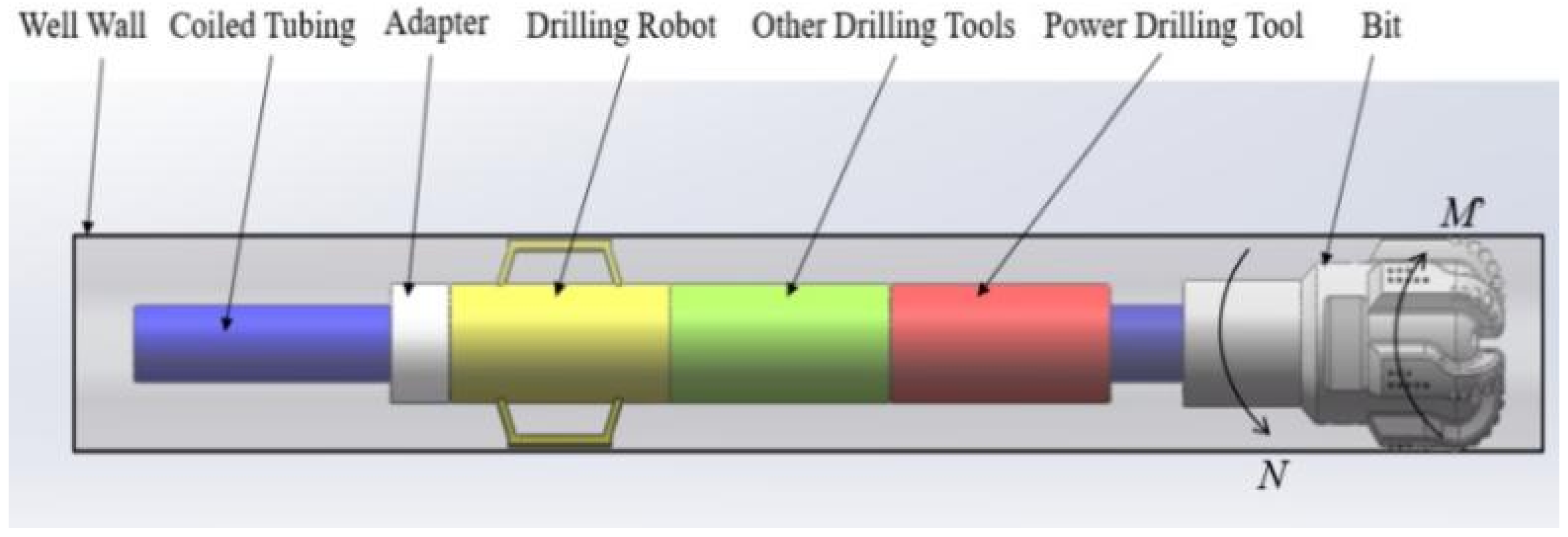
During the actual drilling process, the power drill tool provides the torque to drive the drill bit to break the rock. When the drill bit breaks the rock, the rock will generate a reaction torque on the drill bit. The reaction torque is transmitted to the coiled tubing through the bottom drill tool, as shown in
Figure 1. The drill bit in real drilling will produce torsional vibration, which will cause torsional vibration of the coiled tubing. Torsional vibration will reduce the sealing performance of the CTD and shorten the service life of the CTD robot. Therefore, the CTD robot developed in this paper needs to overcome the anti-torque. The CTD robot mainly overcomes the reaction torque through the contact between the friction block and the well wall.
Assuming that the CTD robot has three axisymmetrically arranged support arms, there are three axisymmetrically arranged friction blocks in contact with the borehole wall. Therefore, the CTD robot shown in
Figure 1 generates continuous reaction torque during the drilling process. The arrangement of the friction block teeth on the well wall is shown in
Figure 2, where
is the angle between the connecting rod and the radial direction of the drilling robot body, °, and
and
are the angle between the friction block and the push block, °.
Figure 3 shows the force model of robot friction block. From the figure, it can be seen that in order to overcome the reaction torque, the CTD robot is subjected to the circumference of the well wall. The frictional force
directly acts on the friction block of the CTD robot. The friction block of the CTD robot is also subjected to the axial friction force
. The axial friction force is mainly to overcome the reaction force of the traction force
of the CTD robot.
If the friction block can overcome the reaction torque generated by the rock breaking of the drill bit without slipping, the force condition in the above figure should meet the following formula:
where
is the i-th circumferential friction force of the wellbore to the friction block, N;
is the wellbore diameter, m; and
is the drill bit reverse torque, N·m.
Assuming that the circumferential friction force of the wellbore against each support block is the same, the calculation formula (2) for the circumferential friction force of any friction block can be obtained:
where
is the circumferential friction force of the shaft against any friction block, N.
Considering the three friction blocks as a whole, according to the static balance relationship, the formula of axial friction and traction in
Figure 3 is as follows:
where
is the i-th axial friction force of the shaft against the friction block, N.
Assuming that the axial friction force of the wellbore to each support block is the same, the calculation formula for the axial friction force of any friction block can be obtained:
where
is the axial friction force of the shaft against any friction block, N.
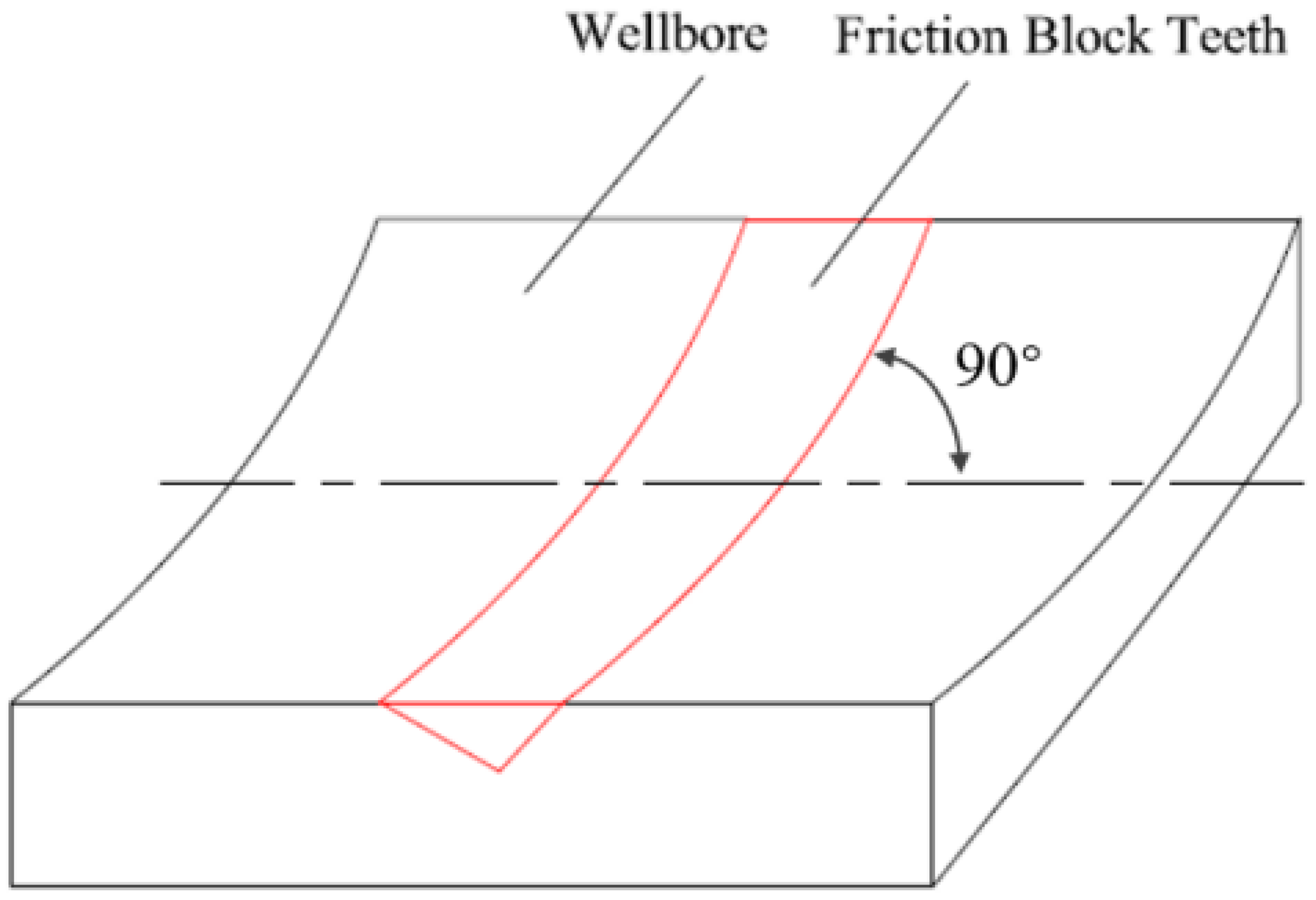
In order to increase the friction between the friction block of the CTD robot and the wellbore so that the friction block can effectively support the wellbore, teeth are usually machined on the friction block, and the teeth of the friction block are distributed at 90° to the axis of the wellbore (
Figure 4).
According to the working mechanism of the CTD robot, a schematic diagram of the force on a single tooth of the friction block tooth is established as shown in
Figure 5.
In order to simplify the calculation, the friction block teeth of the CTD robot in
Figure 5a are simplified to the triangular prism friction block teeth in
Figure 5b. Assuming that the teeth are grasped stably and no slippage occurs, the teeth of the friction block in
Figure 5 should meet the following conditions:
From the above formula, combined with the force analysis in
, the formula is derived as follows:
where
is the axial traction reaction force on a single tooth of the friction block of the CTD robot,
;
are the friction force in different directions on a single tooth of the friction block of the CTD robot,
;
is the axial-included angle of the friction block teeth of the CTD robot, °;
are the tilt angle of the friction block teeth of the CTD robot, °;
are the positive pressure on the inclined surface of the friction block of the CTD robot,
;
is the circumferential force on a single tooth of the friction block of the CTD robot,
;
is the radial support force of a single tooth of the friction block of the CTD robot,
.
When the friction block teeth are pressed into the casing or well wall, both sides of the teeth are subjected to the force of the casing or well wall. However, when the CTD robot is drilling normally, the front of the friction block teeth will bear the entire load, so the formula (7) can be simplified:
In fact,
and
should meet the following conditions:
where
is the friction coefficient between the teeth of the friction block of the robot and the wellbore constant. Combining formulas (8) and (9), the following formula can be obtained:
The tooth load of the friction block of the CTD robot can be obtained by the following formula:
where
is the number of friction teeth of the CTD robot, and
is the inner diameter of the wellbore, m. Combining formulas (9) and (10), the following formula can be obtained:
where
is the resultant force of the tooth slope of the friction block of the CTD robot, N.
3. Analysis of Influencing Factors on Statics Characteristics of Friction Block Teeth of CTD Robot
In order to analyze the static characteristics of the friction block teeth of the CTD robot, the following two points are explained for the initial parameter setting:
(1) The traction force FT of the CTD robot adopts 30,000 N;
(2) The reaction torque of the CTD robot is determined by the downhole power drilling tool screw. The downhole power drilling tool used in CTD is usually a small size power drilling tool (0.089 mm or 0.095 mm screw drilling tool). The rated torque of small screw drilling tool is about 1000 N·m, and the torque that can be provided generally does not exceed 2000 N·m, so the reaction torque it can generate will not exceed 2000 N·m. That is to say that as long as the CTD robot support mechanism can withstand sufficient reverse torque, the CTD robot can successfully drive the downhole drilling tool well. To improve the ability of the CTD robot to withstand the reverse torque, this article assumes that for the CTD robot, the maximum torque that can be withstood is 2000 N·m, that is, the reaction torque M = 2000 N·m.
(3) The number of teeth in the friction block is mainly determined by the shape of the teeth and the damage to the wellbore. In order to be able to calculate the formula (9) numerically, the number of teeth is tentatively set here as
, and the inner diameter of the wellbore
.
,
,
,
,
,
,
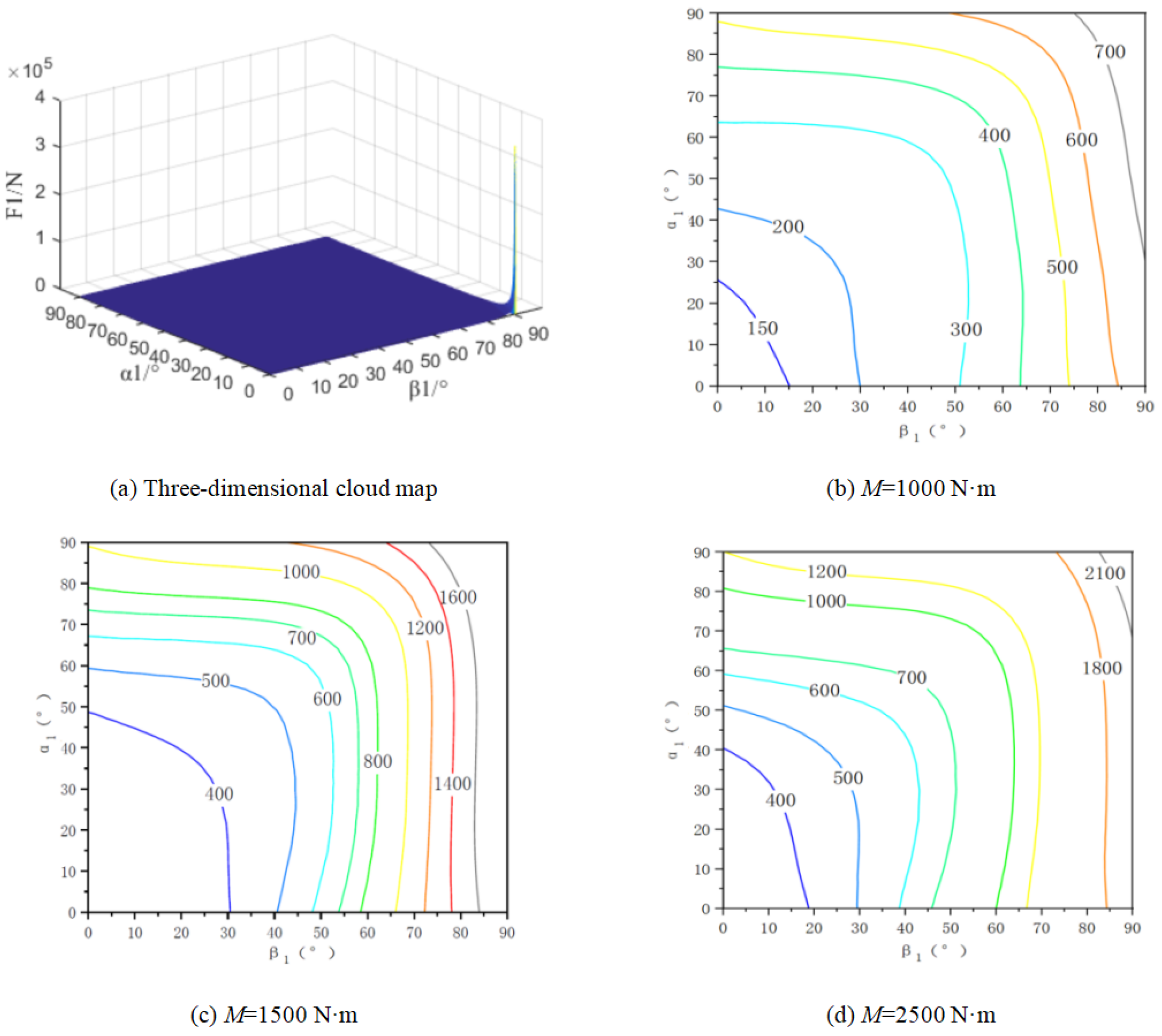
. Bring the above parameters into the Formulas (11) and (13), and calculate the changes in the mechanical characteristics of the friction block teeth of the CTD robot as shown in
Figure 6 and
Figure 7.
3.1. The Influence of , and M on Supporting Force
The following can be seen from
Figure 6:
(1) With the increase in , the supporting force of the CTD robot increases. When is small, the change of is small, and when is large, the change of is large.
(2) When is a certain value, with the increase in , increases, and the magnitude of the change is relatively large.
(3) The curve of is the criticality of self-locking, that is, the parameters of and are on the left side of . The friction block of the CTD robot can realize self-locking support. On the contrary, the parameters of and are at . The right side is non-self-locking support.
(4) Within the range of and , the F s changes greatly, which exceeds the limit of the supporting force that the coiled tubing CTD robot can provide.
(5) As the reaction torque M increases, the self-locking critical line shifts to the left, that is, with the increase in M, if the CTD robot is to realize the self-locking function, the angle should decrease accordingly.
3.2. The Influence of , and M on the Force of Friction Block Teeth
(1) With the increase in , the force of the wellbore on the friction block teeth of the CTD robot first decreases and then increases. The reasons are as follows: (a) When the value of is relatively small, the friction block teeth can effectively resist the reaction torque. At this time, the main factor that affects is the axial force. When increases, it can be done without adding additional force, bearing part of the axial force, so is reduced. (b) When the value of is relatively large, also due to the principle of self-locking of the inclined surface, the friction block teeth can effectively resist the axial force. At this time, the main factor affecting is the reaction torque. When increases, in order to resist the action of the reaction torque, increases.
(2) As
increases,
increases. It can be obtained from
Figure 7 that the smaller
and
are, the smaller
is, that is, the force between the teeth and the wellbore is also smaller.
(3) As the reaction torque M increases, under the same conditions of and , increases.
3.3. The Influence of , and on Supporting Force
Assuming
M = 2000 N·m, the supporting force change law shown in
Figure 8 is obtained. It can be seen from the figure that with the increase in
, the self-locking critical line
= 0 of the CTD robot shifts to the right, that is, with the increase in
, the optional range of
is actually expanded. The reason is that the friction block is traction in the axial direction. Self-locking support can be realized in the
direction, and the traction force promotes the positive pressure of the friction block on the wellbore, which is much larger than the critical value of the axial slip of the friction block. The margin can offset the positive pressure of the circumferential torsion, which is much larger than the critical value of the axial slip of the friction block. The value margin can offset the positive pressure of the circumferential torsion, which is much larger than the critical value of the axial slip of the friction block, and the margin can offset the circumferential torque
M. Therefore, when
M does not change, the self-locking range of
is expanded.
3.4. The Influence of Friction Coefficient and on Supporting Force and
Assuming
= 30,000 N,
M = 2000 N·m, the influence law of friction coefficient on supporting force
as shown in
Figure 9 is obtained. It can be seen from
Figure 9a that (1) as
increases,
gradually decreases, and (2) as
increases,
gradually increases.
It can be seen from
Figure 8b that (1) with the increase in
,
gradually decreases, and (2) with the increase in
,
does not change. Through the above analysis, the size of
affects
and
at the same time, and the trend is opposite, so a more appropriate friction coefficient should be selected in the actual application process;
only affects
, but has no effect on
, so
should be as small as possible.
3.5. The Influence of , and M on Supporting Force
Assuming:
= 30,000 N,
= 45°,
= 45°, the influence law of
,
,
M on supporting force on supporting force
as shown in
Figure 9 is obtained. The following can be seen from
Figure 10:
(1) With the increase in and , gradually increases;
(2) The self-locking critical line = 0 is only related to , and has nothing to do with ;
(3) With the increase in M, the self-locking critical line =0 moves to the left. The reason is that the friction block can achieve self-locking support in the direction of the shaft traction force . The traction force promotes the positive pressure of the friction block on the wellbore. The pressure is far greater than the critical value of the axial slip of the friction block, and the positive pressure margin can offset the circumferential torque M. Therefore, when M changes, the self-locking positive pressure margin is not enough to resist the action of the torque. Therefore, in order to achieve self-locking under different torque conditions, the value of should be calculated under the limit torque conditions.
The mechanics models developed in this paper are all based on the self-locking mechanics model. However, under complex downhole drilling conditions, if the downhole tools are prone to failure and self-locking, it may cause serious downhole sticking accidents. Therefore, the downhole tool design is being carried out. At the time, the non-self-locking structure parameters close to the self-locking condition can be selected. This solution can not only effectively improve the working performance of the CTD robot, but also ensure that the CTD robot will not self-lock in actual working conditions.
4. Experimental Analysis
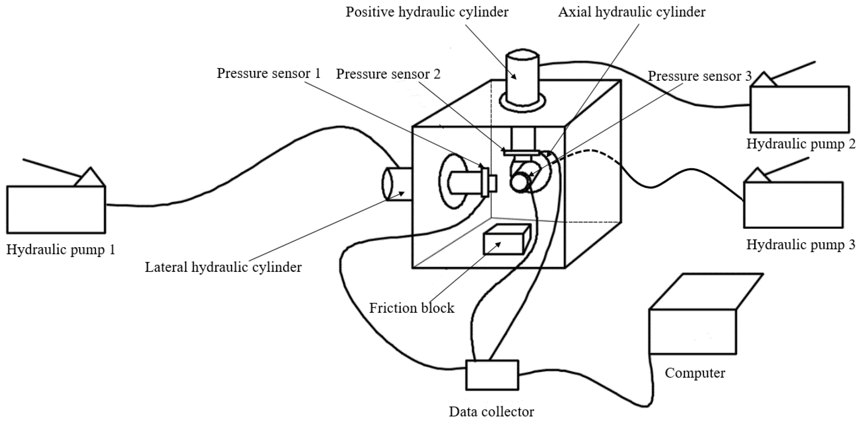
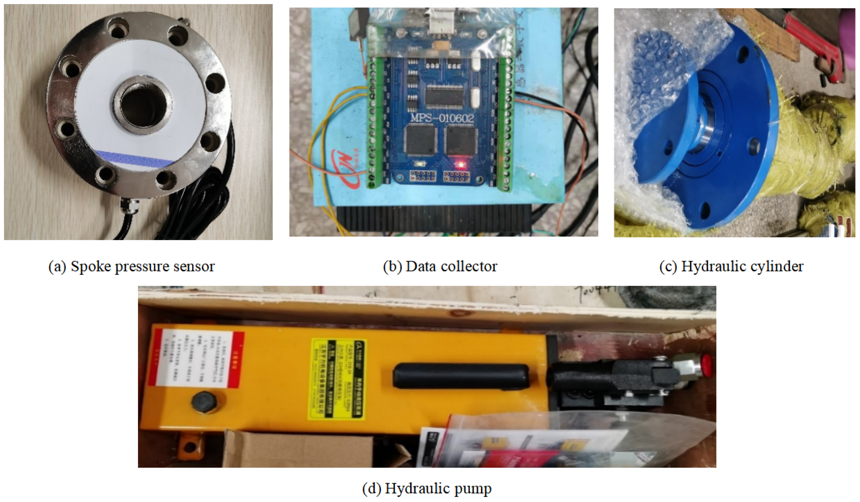
The schematic diagram of friction block performance experiment system as shown in
Figure 11. The part of the physical map of the experimental device as shown in
Figure 12. The external image of experimental device as shown in
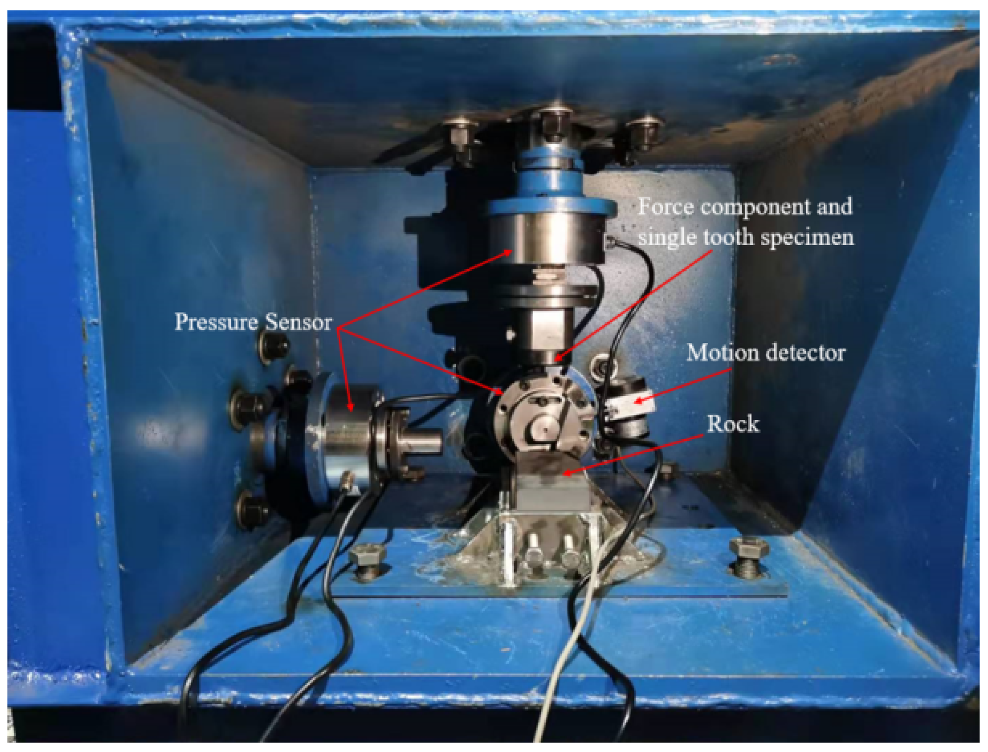
Figure 13. The internal diagram of the experimental device as shown in
Figure 14. The experimental goal and experimental principle are as follows:
(a) Experimental goal: By applying simulated radial positive pressure and axial traction to a single tooth, the state and performance of different single tooth profiles are tested, and the equivalent friction coefficient of the corresponding conditions is obtained. Then, the self-locking performance of different tooth profiles is judged.
By applying simulated radial positive pressure, axial traction force and lateral torque force to a single tooth, test the pressing and damage of a single tooth to the borehole wall, subject a single tooth with different angles to axial traction and lateral torque at the same time performance under the condition of force, analyze the contact effect, and obtain the equivalent friction coefficient of the corresponding condition.
(b) Experimental principle: The experiment scheme of friction block tooth single tooth is shown in the figure, in which the driving force of the hydraulic piston simulates the supporting force, axial force and torque. Install tension and compression sensors on the hydraulic piston to test the supporting force, axial force and torque, respectively. Perform rock simulation of open hole wall.
4.1. Single Tooth Simulation Experiment
Select the angle of the tilt angle of friction block teeth
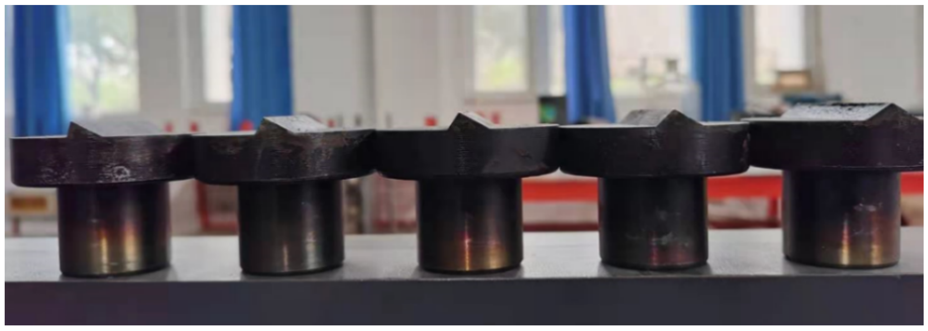
to be 22°–55°, and set the positive pressure range to 2000–6000 N. The single tooth specimen after quenching as shown in
Figure 15. Install rock and fixed single tooth, press the forward hydraulic pump to the specified positive pressure
, pressurize the axial hydraulic pump, and observe the displacement. When the displacement sensor reaches 5 mm, it is regarded as the grip failure. Record the display of the axial pressure sensor at this time data
, and draw a data graph.
As shown in
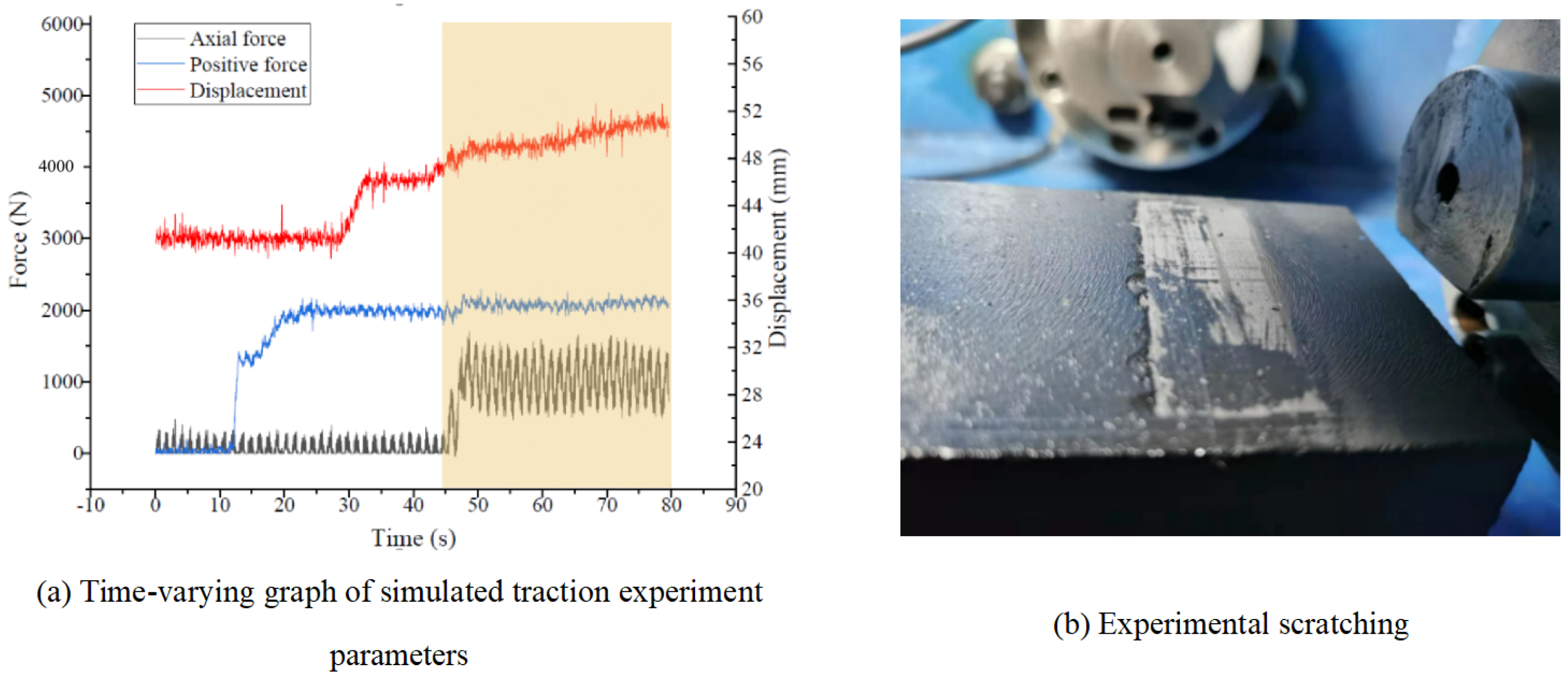
Figure 16a, the red curve in the figure is the displacement curve. One end of the displacement sensor is fixed to the inner wall of the device, and one end is fixed to the flange of the axial hydraulic cylinder, so there is an initial displacement in the figure; it starts when the friction tooth has not touched the rock sample. Record the data. After about 10s, the friction tooth touches the rock sample, and the pressure rises rapidly, reaching the set value of 2000 N in about 25 s. Starting from about 30 s, the axial hydraulic cylinder moves, and the rear force component gradually approaches the single-tooth indenter. The displacement increases rapidly; at about 40 s, the rear force application component contacts the single-tooth indenter and starts to push the single-tooth indenter to move. At this time, the axial pressure sensor display increases rapidly, and the displacement also increases slowly. During the sliding process, due to the short sliding distance, the positive pressure does not change much, and the axial force tends to be stable.
After intercepting the pressure data of the displacement section (shaded area of
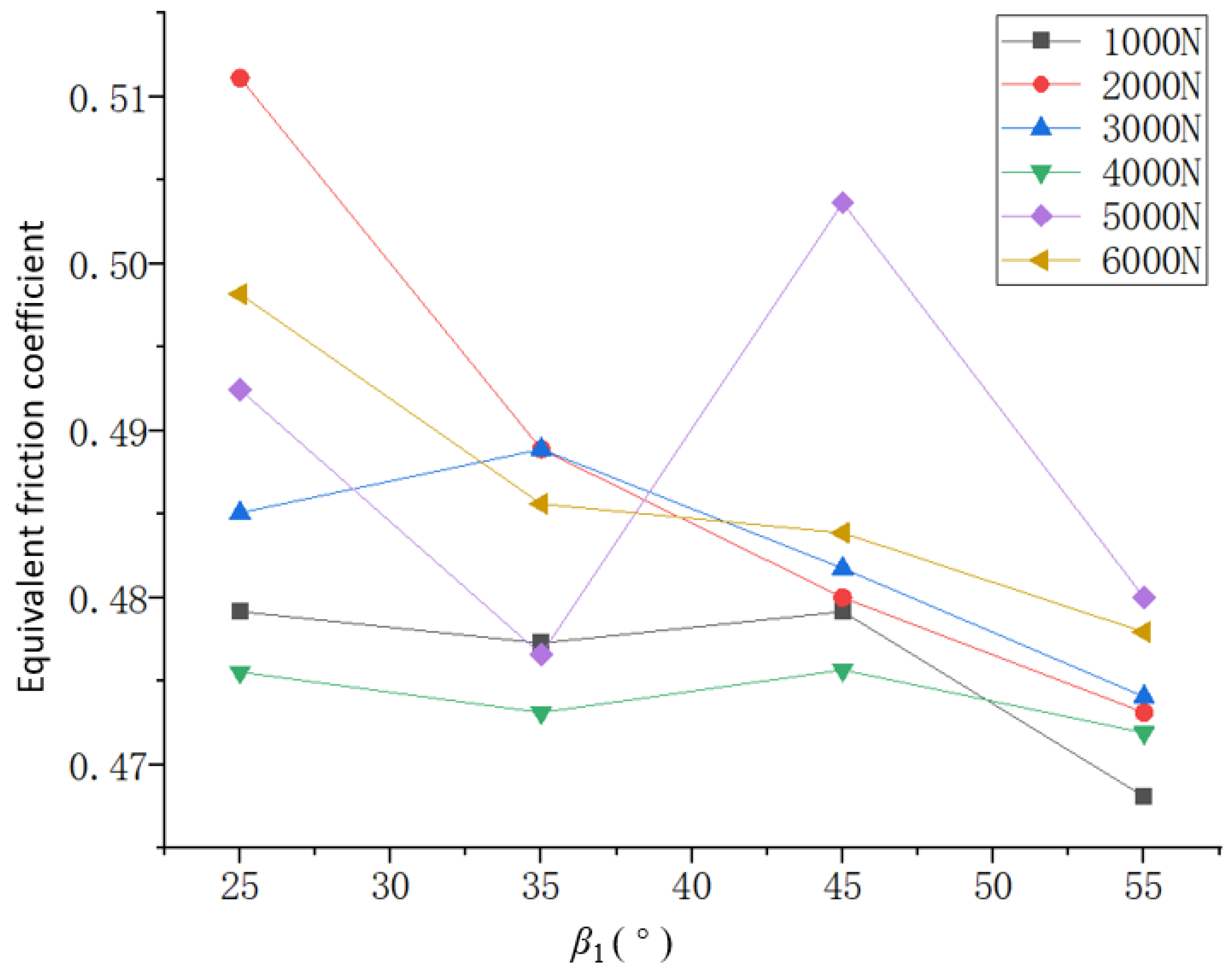
Figure 16a) and calculating the equivalent friction coefficient, the data are numerically fitted, and the friction coefficient of the stationary section is intercepted to obtain the equivalent friction coefficient as shown in
Figure 17.
It can be seen from
Figure 17 that as
increases, the equivalent friction coefficient tends to gradually decrease. This is because under the same positive pressure, the increase in the rake angle leads to a decrease in the embedding depth. The sliding equivalent friction coefficient range of friction tooth contact with well wall is about 0.47–0.52. Comparing the friction coefficient of shale slab [
19], it shows that setting
30° on the friction block can significantly increase the equivalent friction coefficient, thereby improving the self-locking effect of the support mechanism.
4.2. Single Tooth Shaft and Torsion Coupling Simulation Contact Experiment
Select the friction teeth with the tilt angle of friction block teeth of 30°, set the positive pressure to 3000 N, respectively carry out the axial included angle of friction block teeth in the range of 60°–90°, install the rock and the fixed single tooth, and pressurize the positive hydraulic pump to the specified positive force . The axial hydraulic pump and lateral hydraulic pump apply pressure at the same time. When there is obvious sliding, record the data displayed by the pressure sensor at this time axial force and lateral force , and draw the data graph.
The curve changes of the axial force and the lateral force in
Figure 18 are almost synchronized, which realizes the design and simulation of the shaft torsion coupling load, and the effect of simultaneous loading of the axial force and the lateral force. Due to the load in both directions at the same time, due to the sensor error, the lateral force output load fluctuation in the figure is relatively large, but the values and laws of the two are almost the same, so the two calculations are based on the same equivalent friction coefficient.
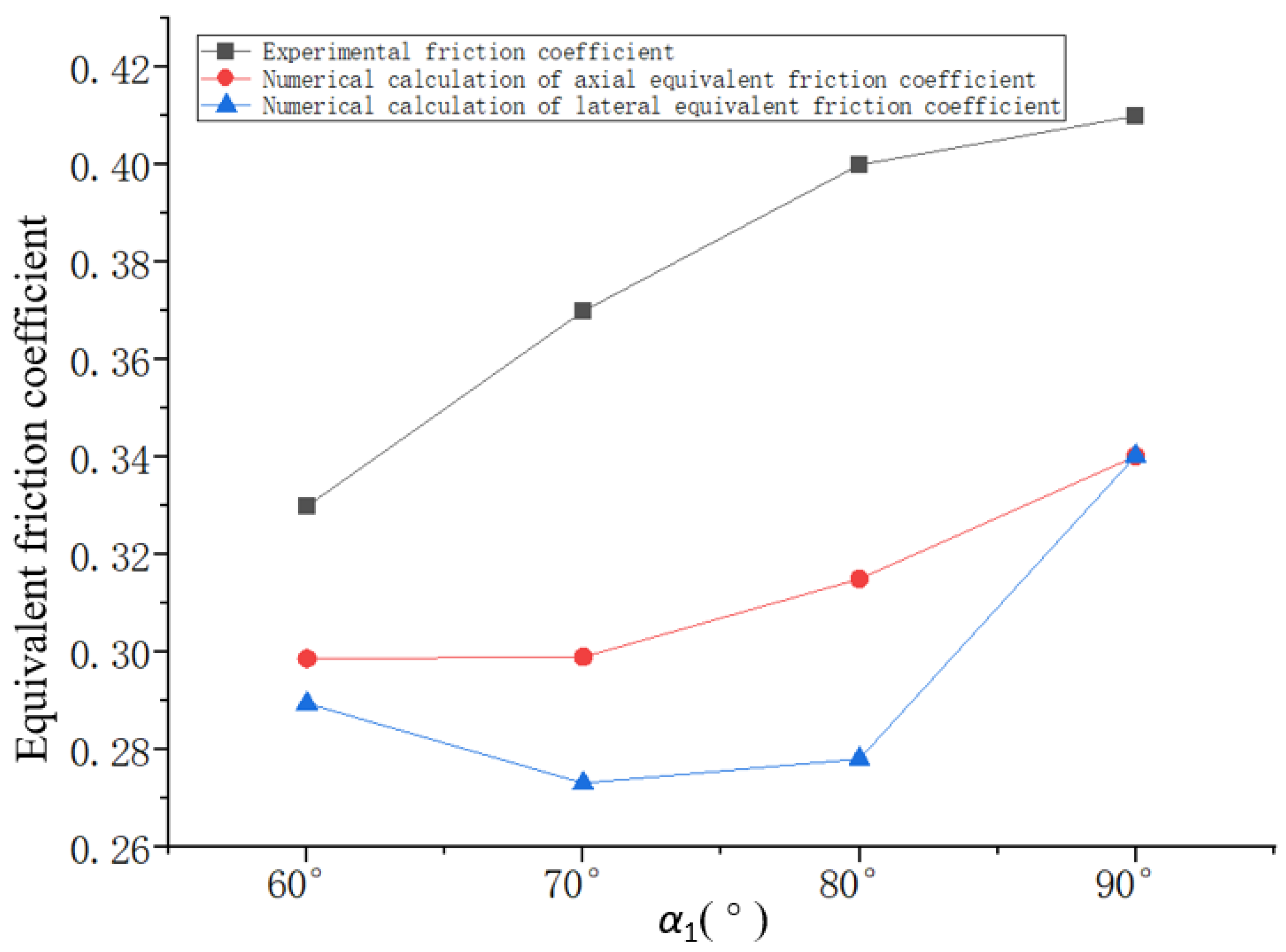
Summarize the values obtained from the fitting curve in the figure, calculate the equivalent friction coefficient, and establish the same multi-directional force numerical model of the helical tooth in the simulation software to obtain the simulated axial and lateral equivalent friction coefficients of the numerical calculation. Draw them together as shown in
Figure 19.
It can be seen from
Figure 19 that the equivalent friction coefficient obtained under the single-tooth simulation shaft and torsion coupling condition is slightly smaller than the value obtained in the experiment compared with the friction coefficient of the numerical simulation. Therefore, under the condition of similar friction coefficients between materials, the slaw of numerical simulation and experiment are similar, and both show a downward trend, but the value of the equivalent friction coefficient is low, indicating that the actual sliding load of the tooth is not deep in the actual contact. It should be greater than the result of the numerical simulation. When the experimental equivalent friction coefficient is 0.33–0.41, and
is about 90°, the self-locking performance is the best.
6. Conclusions
According to the requirements of the CTD robot’s large traction force and small size, this paper mainly carried out the research on the statics characteristics of the friction block of the CTD robot’s large traction force support mechanism.
(1) Based on the research of domestic and foreign literature, analyzing the mechanical characteristics of the supporting mechanism of the drilling robot, combined with the actual working conditions of CTD, a static model of the friction block teeth of the CTD robot under the combined action of anti-torque and axial load is established. When teeth are processed on the friction block, the critical condition for autonomous support of the inclined block will change, that is, the inclination angle of the support block that plays a role in self-locking will increase. The axial included angle of the friction block teeth is > 5°, and the inclination angle of the friction block teeth is < 85°, which can effectively assist self-locking. The CTD robot bears the axial load and the torsional load at the same time. When the torsional load is smaller than the axial load to a certain extent, the CTD robot can realize self-locking support. This is because the axial load is torsion while achieving axial self-locking. The load provides a certain amount of axial self-locking support force margin.
(2) Through analysis, it is found that the CTD robot can only be locked under the reaction torque, that is, use the support force margin generated by the axial traction force to withstand the reaction torque of the CTD robot. When the reaction torque of the drilling robot is greater than the traction force, the support of the CTD robot will fail with the generated supporting force margin, so the CTD robot cannot achieve anti-torque self-locking.
(3) The interaction mechanism between different tooth parameters and the well wall/pipe wall is revealed, and the design principle of friction block teeth that can withstand the reaction torque while providing axial force is obtained.
(4) Through a single-tooth simulation traction experiment, under the condition of a positive pressure of 1000-6000 N and the tilt angle of friction block teeth 25–55°, the equivalent friction coefficient calculated by the experiment is in the range of 0.47–0.51. Through the single pinion torsion coupling simulation contact experiment, when is 30°, the positive pressure is 3000 N, the axial included angle of the friction block teeth is 60–90°, and the equivalent friction coefficient calculated by the experiment is in the range of 0.33–0.41. Combining the two, it is obtained that the self-locking performance is the best when is about 30° and is about 90°. This provides a reference for the design of the friction teeth of the support mechanism.
