Article

Study on Oxy-Methane Flame Stability in a Cylindrical Porous Medium Burner

1
The State Key Laboratory of Refractories and Metallurgy, Wuhan University of Science and Technology, Wuhan 430081, China
2
National-Provincial Joint Engineering Research Center of High Temperature Materials and Lining Technology, Wuhan 430081, China
3
Department of Mechanical Engineering, The Hong Kong Polytechnic University, Kowloon, Hong Kong SAR, China
4
The Hong Kong Polytechnic University Shenzhen Research Institute, Shenzhen 518000, China
*
Author to whom correspondence should be addressed.
Processes 2023, 11(7), 2182; https://doi.org/10.3390/pr11072182
Submission received: 20 June 2023 / Revised: 17 July 2023 / Accepted: 19 July 2023 / Published: 21 July 2023

Abstract

:
Combustion in a porous medium can be beneficial for enhancing reaction rate and temperature uniformity. Therefore, considering the combination with oxy-fuel combustion can address some shortcomings in oxy-fuel burners, a cylindrical two-layer porous burner model is established based on OpenFOAM in this paper. A two-temperature equation model is adopted for the simulation of the heat transfer process. The CH4 skeletal kinetic mechanism is adopted for complex chemistry integration based on OpenSMOKE++. Corresponding experimental methods were used for complementary studies. The walls of the burner are wrapped with three types of thermal insulation materials to present different levels of heat loss. The results show that considering the convection and radiative heat loss of the burner wall, the temperature near the wall is reduced by more than 300 K compared to the adiabatic condition. As a result, the flame propagation speed and CO oxidation rate slowed down. The stable range will be destructively narrowed by more than 50%, and CO emissions will increase by more than 10 times. These defects will be aggravated by increasing the diameter of the burner. It is observed that when the diameter of the burner increases from the initial 5 cm to 10 cm, the effect of heat loss on the stable range is insignificant.

1. Introduction

The goal of carbon neutrality will facilitate China’s industrial restructuring from a high-pollution, high-carbon industry mode to a low-carbon one [1]. Fossil fuel burning accounts for 85% of global energy production and remains a major source of anthropogenic carbon dioxide (CO2) and pollution in the atmosphere [2]. As renewable energy sources like wind, hydro, and solar energy are cyclical and susceptible to environmental impacts, it is foreseeable that fossil fuels will continue to dominate energy structure for some time in the future. Therefore, improving fossil energy utilization efficiency and reducing CO2 emissions play an important role in reaching the goal of carbon neutrality strategy. Additionally, carbon capture, utilization and storage technology (CCUS) is currently recognized as a technical means to achieve large-scale CO2 emission, and oxy-fuel combustion is an essential part of CCUS [3,4]. In the oxy-fuel combustion process, pure oxygen is employed for fuel combustion, resulting in only H2O and CO2 as products. The chemical reaction rate and flame temperature are controlled by the CO2 circulating flow [5,6]. Moreover, the combustion-supporting gas does not contain N2, so it does not produce any form of NOx. Compared with N2 in the air atmosphere, CO2 has higher density and heat capacity. Therefore, the CO2 atmosphere usually has the disadvantages of a slow chemical reaction rate and low combustion temperature, resulting in unstable combustion and accompanied by more CO generation [7]. Porous medium combustion (PMC) has emerged as a viable solution to address the aforementioned problems to a significant extent. PMC is an internally self-organized process of heat recuperation that differs markedly from homogeneous flames. The solid matrix of a porous medium has a higher heat capacity, conductivity, and emissivity than gas. This results in significant changes in the combustion process when it takes place within a porous medium. The numerous pores or paths in the solid matrix heat up the fresh reactants as they flow through the medium. Additionally, heat recirculation mechanisms from the burning region to the fresh reactant gas increase the flame velocity, resulting in a high heat release rate at the combustion chamber [8]. PMC has a lot of design freedom since they are able to burn a wide variety of fuels, from ultra-lean to ultrarich mixtures, due to the intense heat exchange from the combustion zone throughout the solid. This form of combustion produces an excess enthalpy flame [9]. Under certain test operating conditions, the apparent burning velocities can exceed the open flame laminar burning velocities by over 40 times [10]. In addition to the benefits mentioned earlier, the use of porous media in combustion processes can also lead to prolonged gas residence times. This is due to the complex and variable flow passageways within the porous medium, which promote efficient mixing and heat transfer. As a result, the heat transfer intensity is significantly increased when compared to combustion without porous media [11]. As the combustion becomes more efficient, the possibility of formation of NOX and CO becomes minimal. It is considered that the unique advantages of PMC technology may make up for the shortcomings of oxy-fuel combustion technology. Therefore, the combination of PMC and oxy-fuel combustion technology may be an efficient and clean fuel utilization technology in the future.
However, the development of porous media combustion technology also faces many challenges, one of which is how to achieve stable combustion [12,13]. In the homogeneous porous medium material, flame stabilization is most commonly attained when the flame speed matches the upstream flow velocity of the air and fuel mixture, but this condition is usually difficult to achieve. More often, the flame will move within the burner, which will lead to a potential risk of blow-out or flashback [14]. The two-layer porous media burner is an ingenious design. Two porous medium materials with different structures are placed in the burner in turn. At the upstream, the flame propagation speed is slower than the gas flow rate, and the flame moves downstream. Conversely, downstream, the flame propagation velocity is greater than the airflow velocity, and the flame gradually moves upward. The final result is that the flame resides at the interface of the two porous medium materials, and stable combustion is achieved. The burner of this structure can achieve stable combustion within a specific flow velocity range rather than a specific velocity value, which is called the stable range. One of the research focuses on PMC is to obtain the stable range of the burner. The factors that affect the stable range are the properties of porous medium materials, such as pore size, porosity, and thermal conductivity [15,16,17].
In the experiments of Arrieta et al. [18], it was found that different equivalence ratios and gas mixture compositions have obvious effects on the temperature, stability, and radiation intensity of the flame. Coutinho et al. [19]. studied the effects of inlet velocity, excess air coefficient, porosity, and thermal conductivity of porous medium materials on the temperature field and pointed out that increasing the inlet mass flow (velocity or energy) can increase the temperature in the burner. Hashemi et al. [20] studied the effects of preheating section and combustion section geometry, equivalence ratio, and inlet velocity on flame stability based on Fluent’s non-thermal equilibrium model. Pan et al. [21]. studied the flammability limits of burners with rectangular, circular, and square cross-sections. The variables include inlet velocity, equivalence ratio, and -OH mass fraction. The researchers discovered that equivalence ratio and intake air velocity play a crucial role in the combustion process, affecting the temperature and flow fields, as well as the concentration of key radicals. Ahmed et al. [22]. studied the combustion behavior of air and oxy-fuel in microchannels. However, their results showed that the temperature difference between oxy-fuel and air-fuel was nearly the same even though the reaction rate in oxy-fuel was lower than the latter.
Moreover, the inserted porous medium obstructs the flow at the center zone and guides it towards the inner wall, which enhances the heat transfer to the wall [23]. This allows PMC technology to be applied in some places that need to rely on radiation for heat exchange, such as radiant burners [24] and thermophotovoltaic (TPV) applications [25]. Nevertheless, it is precisely due to the higher wall temperature of the porous media burner that considerable heat loss is caused. Obviously, this phenomenon will reduce the temperature and flow rate near the wall, which is detrimental to the stable combustion in the burner and may also lead to more CO generation. Many scholars have revealed the influence of the wall effect on flame behavior in the research of mesoscale and microscale porous media combustion. In their research work on porous media burners in thermo-photoelectric systems, Gentillon et al. [26] pointed out that the materials of the thermal insulation layer and the anti-radiation layer of the burner have a significant effect on the flame propagation speed in the burner so that the stable combustion range is significantly different. In a similar study by Peng et al. [27], it was mentioned that there was an optimum burner diameter where the outer wall surface had the greatest radiation capability. Xie et al. [28] simulated a reciprocating porous media burner based on the commercial software Fluent (version 2020 R1); a 2D model was adopted and results were compared with the 1D model. It was also pointed out that wall heat loss is the assumption that has the most significant impact on the model accuracy. It may be difficult to accurately describe combustion characteristics without considering heat loss. Therefore, a two-dimensional model is required, and the convective and radiative heat loss boundary conditions must be considered.
Most of the studies on PMC mentioned above are under air-fuel conditions, while the work on oxy-fuel is still relatively lacking. Under oxy-fuel combustion conditions, the physical parameters (specific heat capacity, thermal conductivity) of combustion-supporting gas are quite different from those under air-fuel conditions. As a result, these differences lead to significant changes in properties such as ignition, with consequent lower reaction rates and more CO emissions. In our previous work [29], the combination of porous media and oxy-fuel combustion technology has been proven to be feasible. Its advantages lie in compensating for the shortcomings of slow reaction rate, low flame propagation speed, and low flame temperature of oxy-fuel combustion technology. However, it also reveals the defects that need to be overcome, one of which is the narrow stable velocity limit. Since the stable limit represents the power adjustment range of the combustion device, this indicator plays an important role in the applicability of the burner. In addition, one of the limitations of the previous research work is that the heat loss on the burner wall was not considered. According to the research of scholars mentioned above, wall heat loss will significantly narrow the stable limit. Therefore, in the current research, the wall boundary conditions are improved, and corresponding experiments are carried out to verify the mathematical model. The main focus of this paper is determining ways to broaden the stable limit and reduce the impact of wall effects on the stable limit. The diameter of the burner is considered a variable to investigate the significance of its impact on the stable limit and to explore the minimum diameter that can resist negative effects. It is hoped that the study in this paper will be helpful to the application of oxy-fuel porous media combustion technology.

2. Research Method

2.1. Experimental Setup

The experimental equipment consists of three components: 1. Two-layer porous media burner; 2. Fuel mixture supply system; 3. Data measurement and collection system. The schematic diagram is shown in Figure 1.
1. Two-layer porous media burner. The primary part of the burner refers to the previous research system by Gao et al. [16]. Alumina pellets with a diameter of 3 mm are used as the porous medium material in the preheating zone of the burner, and the combustion zone is filled with 10 PPI SiC ceramic foam. The thermophysical parameters of the material, which were calculated from empirical equations combined with porosity as well as pore size, are summarized in Table 1. The diameter of the burner is D = 5 cm. To mitigate the potential danger caused by flashback states, a 60 PPI SiC ceramic foam (referred to as Pre-SiC) is installed at the inlet of the burner. This gadget not only reduces the risk of flashback, but also improves the speed uniformity at the entrance of the burner. At the same time, the heat exchange between Pre-SiC and the downstream burner needs to be avoided. Therefore, a cavity between the preheating zone and direct contact between the two layers of porous media is avoided.
In this work, the wall heat loss of the burner is one of the fundamental objects to be investigated. Three types of wall insulation are used to wrap around the side of the burner. As shown in Figure 2, (1) 25 mm thick refractory fiber is an approximately insulated condition, and the burner of this structure is named PMB(A) in the work; (2) 3 mm thick stainless steel shell, due to the low emissivity of stainless steel, represents the heat loss under medium intensity radiation and convection conditions, which is named PMB(B); (3) 3 mm thick quartz glass tube has the ability to withstand high temperature of about 1500 K, and it is transparent to the radiated light of the porous material of the burner, representing the maximum intensity of radiation and convective heat loss conditions, which is named PMB(C). It is pointed out here that due to the temperature limitation of the experimental equipment, only a part of the conditions (temperature within 1500 K) is experimentally studied.
2. Fuel mixture supply system. The mixture entering the burner is CH4 and O2 diluted with CO2. The gas enters the gas supply pipeline from the gas cylinder (99.99%) through the mass flow controller (2% accuracy of full scale). A four-way valve is used for the first premix of the species. Subsequently, the mixed gas is briefly held in the porous media mixer to achieve adequate premixing. The mixer is a tubular cavity with a diameter of 30 mm and a length of 70 mm, and the interior of the mixer is filled with inert glass spheres of 10 mm in diameter. After that, the mixed gas enters the burner through pipes.
3. Data measurement and collection system. The key parameters to be measured in this work include the temperature field inside the burner and the emission concentration at the outlet. A total of 9 locations on the burner are perforated for thermocouple placement. This corresponds to 9 S-type thermocouples with a diameter of 2 mm and an uncertainty error of ±2.5 K that are distributed on the central axis of the burner. It should be noted that to capture the temperature changes in the burner, the thermocouples are not equally spaced in the burner. As shown in Figure 3, there are three in the preheating zone, five in the combustion zone, and the remaining one is located at the interface, and they are more inclined to be placed in the area with a relatively large temperature gradient. A data collector model (NI cDAQ-9174 and NI 9214) is used to collect temperature data measured by thermocouples, and the supporting NI LabVIEW (version 2020 SP1) commercial software is used to display the data. In addition, a hand-held K-type thermocouple and FLUKE TiX660 thermal imaging system are used to measure the burner wall temperature. The gas analyzer Testo350 pro is used for CO measurement at the outlet. The experimental equipment is included in Table 2.
At the beginning of the experiment, each pure species is transported in the pipeline to the mixing valve and mixer to be fully mixed. Since the solid matrix is not preheated, the O2 fraction provided at this time is higher than the preset value. The premixed gases are ignited at the burner outlet using a long-nose lighter. Due to the excess O2, the flame is able to reach a fairly high temperature, and thus the flame propagates towards the preheated zone. After a few minutes, the combustion zone is sufficiently preheated, and then the O2 fraction is adjusted back to the preset value. The system reaches a steady state after about 20 min, at which time the flue gas analyzer and thermal camera are used to collect the flue gas composition and burner wall temperature.
It should be pointed out that a large number of thermocouples are used to collect the burner temperature in this work. Since the diameter of the thermocouple is close to the pore size of the porous medium material, it will hinder and interfere with the flow field, thus having a non-negligible effect on the temperature field. There is no clear conclusion on whether the temperature will increase or decrease. At the same time, some researchers pointed out that the temperature obtained by the measurements exhibits values between the calculated gas and solid phase temperatures, which indicates the influence of the solid phase radiation [30].

2.2. Mathematical Model

2.2.1. Governing Equations

Modeling the porous medium combustion system is intensive in terms of both time and money [31]. Due to the complex structure of porous medium materials, primarily ceramic foams, the physical structure is challenging to model directly and geometrically [32,33]. Consequently, simplified porous models have been widely applied to solve the temperature field. Based on the CFD solver OpenFOAM (version 8) coupled with OpenSMOKE++, numerical models of a two-layer porous burner are established. Combined with the methane skeletal kinetic mechanism (24 species, 155 reactions) [34], the laminar combustion process in the porous media burner is simulated. In the mathematical model, the potential catalytic effects of the high-temperature solid are negligible. Moreover, the Dufour effect is negligible. The governing equations included are as follows:
Continuity equation:
ε ρ g t + ε ρ g U = 0
Momentum equation:
ε ρ g U t + ε ρ g U U = P + μ U + S i
where ε is the porosity of the porous media, ρ g is the density of the premixed gas, and μ is the dynamic viscosity. The Ergun resistance model source term S i is defined as [35]:
S i = 180 1 ε 2 ε 3 U u i d 2 + 1.8 1 ε ε 3 ρ g u i U d
where d is the pore diameter.
Gas-phase energy equation:
t ε ρ g C g T g + U ε ρ g C g T g = ε λ g T g ε i = 1 N ω i h i W i S
Solid-phase energy equation:
1 ε t ρ s C s T s = λ e f f T s + S
where C and λ are the heat capacity and thermal conductivity, respectively, and ω i , h i , and W i are the molar production rate, molar enthalpy, and molecular weight of the i-th species, respectively. The subscripts g and s denote the gas and solid matrix, respectively. The temperature source term S of the two equations is defined as:
S = H v T g T s
The above formula indicates the convective heat transfer rate between the gas and solid matrix, and H v is defined as the volumetric heat transfer coefficient:
H v = N u v λ g d 2
In the above equation, N u v is defined as the volume-based Nusselt number:
In packed beds [36]:
N u = 1.18 Re 0.58 4 + 0.23 Re / ε 0.75 4 1 / 4 1 Re / ε 7.7 × 10 5
In foams [37]:
N u v = 0.819 1 7.33 d / L Re 0.36 1 + 15.5 d / L ( 5.1 Re 564 , 0.005 < d / L < 0.136 )
where L is the thickness of the solid matrix, and Re is the Reynolds number with the pore diameter as the characteristic length.
The radiation diffusion model has been employed to simulate the radiation heat transfer process in the solid matrix [38]. In Equation (5),   λ e f f is the equivalent thermal conductivity, which consists of two parts:
λ e f f = λ s + λ r a d
where λ r a d is the radiant thermal conductivity and is defined as:
λ rad = 16 σ T s 3 3 k
where k is the radiative extinction coefficient, obtained from Howell [39], and it is given by:
k = 3 d ( 1 ε )
The model is valid for pore diameters larger than 0.6 mm.
Species transport equation:
ρ Y i t + ρ V Y i = ω i W i
where Yi and V are the mass fraction and diffuse velocity, respectively, of the i-th species.
The ideal gas equation of state is adopted to calculate the density:
ρ g = W ¯ P R T g
In the above equation, W   ¯ is the average molar mass of the mixture gas, and R is the universal gas constant.
For the basic chemical solver reactingFoam in OpenFOAM, some assumptions used in the prediction of the species diffusion coefficient may not be appropriate [40]. Therefore, the code was ported to laminarPimpleSMOKE based on OpenSMOKE++ for simulating laminar reactions with detailed mechanisms. The species diffusion coefficients in the solver are calculated by using the mixture-averaged approach. The time step was selected to be approximately 10−5 s with a corresponding Courant (CFL) number of 0.3. High-temperature ignition method is adopted, and the preheating zone temperature is initialized to 1300 K. The maximum temperature and the flame front position are monitored as a reference for reaching a steady state. Due to the large thermal inertia of the solid matrix, the burner system takes at least 15 min to reach a steady state position. This means that one case requires unacceptably more than 10 days of computation time, which is also too expensive for the work. Consequently, the time of the conjugate heat transfer is scaled, accompanied by scaling the product of density and heat capacity of the solid. The scaling will affect neither the Fourier nor the Biot number of the problem for transient simulations [41,42]. This method reduces the computational cost by more than 10 times.

2.2.2. Boundary Conditions

The following boundary conditions of the 2D model were adopted for the gas, solid, and species:
Inlet (x = 0 cm):
T g = T g , i n l e t = 300 K
( 1 ε ) λ e f f T s x = 0
Y i = Y i , i n l e t , i = 1 , 2 , N
u = u i n l e t v = 0
Outlet (x = 12 cm):
T g x = 0
1 ε λ e f f T s x = ε σ T s 4 T 0 4
Y i x = 0 , i = 1 , 2 , N
u x = v x = 0
where T0 = 300 K is the ambient temperature, ε is the emissivity of the solid material, and σ is the Stefan–Boltzmann constant (5.67 × 10⁻⁸ W/(m2·K4)).
Side wall (y = 2.5 cm):
T g y = 0
1 ε λ e f f T s y = 0
Y i y = 0 , i = 1 , 2 , N
u = 0 v = 0
Velocity inlet and pressure outlet are adopted as boundary conditions at the burner inlet and outlet, respectively. The axisymmetric boundary conditions (y = 0 cm) and wedge boundary condition (z-direction) are adopted by the 2D model.

3. Results and Discussion

3.1. Combustion Behavior of PMB(A)

Our previous work [29] presents simulations and experiments of oxy-fuel combustion in a porous solid matrix, a relatively new area of research that aims to address some of the shortcomings found in oxy-fuel burners (high temperatures and poor uniformity). In the simulations and experiments, the combustion behavior of PMB(A) is studied in detail. Variables include porous medium material parameters and premixed gas composition. Table 3 shows the combustion behavior of PMB(A), which includes the minimum (Vmin) and maximum (Vmax) velocity values and the corresponding peak temperature (Tg,vmin and Tg,vmax) and CO emissions (COvmin and COvmax) at the outlet under stable combustion conditions. The mentioned Vmin and Vmax refer to the velocity limit value for maintaining the flame front stationary on the interface of two layers of a solid matrix. It can be foreseen that the fuel entering the burner increases with the equivalence ratio (φ) or O2 fraction, resulting in a greater heat load, higher combustion temperature, and faster flame propagation. As a consequence, a faster inlet velocity is required to locate the flame at the interface of the two layers of material while avoiding the occurrence of flashback. The results show that the Vmin and Vmax for the stable range will be significantly faster as the heat load increases. In addition, it can be seen that the effect of the inlet velocity of the premixed gas on the combustion peak temperature is within 150 K. However, the peak temperature will increase rapidly by about 100 K when the flame enters the combustion zone from the preheating zone. As a complementary analysis, Figure 4 reveals the gas temperature field of PMB(A) under velocity conditions of 7 and 8 cm/s. The most remarkable result is that when the inlet velocity increases to 8 cm/s, the primary chemical reaction occurs in the combustion zone instead of the preheating zone. The pore diameters of the former suddenly increase, which reduces the convective heat transfer between the high-temperature gas and the solid matrix. As a result, the heat released by the chemical reaction is retained in the gas phase, resulting in a higher flame temperature.
Influenced by combustion temperature and residence time, CO emissions will first decrease and then increase with the increases in equivalence ratio and O2 fraction. Preferably, Table 2 also reflects that when the flame peak temperature is controlled between 1300 K and 1700 K, the CO fraction will be below 5 ppm. When the flame temperature is lower than 1300 K, the oxidation rate of CO is slow, and the residence time is not enough to complete the oxidation to CO2. According to the characteristics of PMC, the flame temperature and the inlet velocity of the premixed gas are related. If the flame temperature is higher, faster inlet velocity is required to achieve stable combustion. The result is a rapid reduction in residence time with increasing temperature. When the temperature is higher than 1700 K, the residence time becomes the limiting factor hindering the oxidation of CO, resulting in the gradual increase of CO.

3.2. Combustion Behavior of PMB(B) and PMB(C)

The diversion effect of the internal structure of the porous medium material on the high-temperature exhaust gas will lead to more high-temperature gas to the wall of the burner, which will significantly increase the wall temperature, resulting in more radiation and convective heat exchange to the external environment. In addition, due to the existence of the porous matrix and its high emissivity, the PMC burner has considerable advantages in heat radiation capability. Thus, radiant heating is one of the potential applications for PMC burners, such as thermophotovoltaic systems and dryers. It can be easily predicted that the effect of heat loss on the flame temperature can be significant, which in turn affects the flame propagation speed and stability. Its impact and how to avoid it are the focus of this work. Therefore, PMB(B) and PMB(C), which with different thermal insulation forms, were compared in detail in this section. The stable range, temperature fields, and CO emission were quantitatively analyzed to study the effect of wall heat loss on combustion characteristics. For PMB(B), since the emissivity of stainless steel is highly temperature-dependent, the average value was adopted, which was 0.2 in the preheating zone and 0.4 in the combustion zone. Quartz glass is translucent but has a lower transmittance for rays with wavelengths above 4.2 um. Some researchers have revealed that the radiant thermal power of alumina through the quartz wall only accounts for less than 10% of the total radiance [43]. Therefore, for PMC(C), the emissivity of the quartz glass at 1000 K (0.8) is used. The following are the boundary conditions of the burner wall of PMB(B) and PMB(C):
Side wall (y = 2.5 cm):
T g y = 0
1 ε λ e f f T s y = ω σ T s 4 T 0 4 h f ( T s T o )
Y i y = 0 , i = 1 , 2 , N
u = 0 v = 0
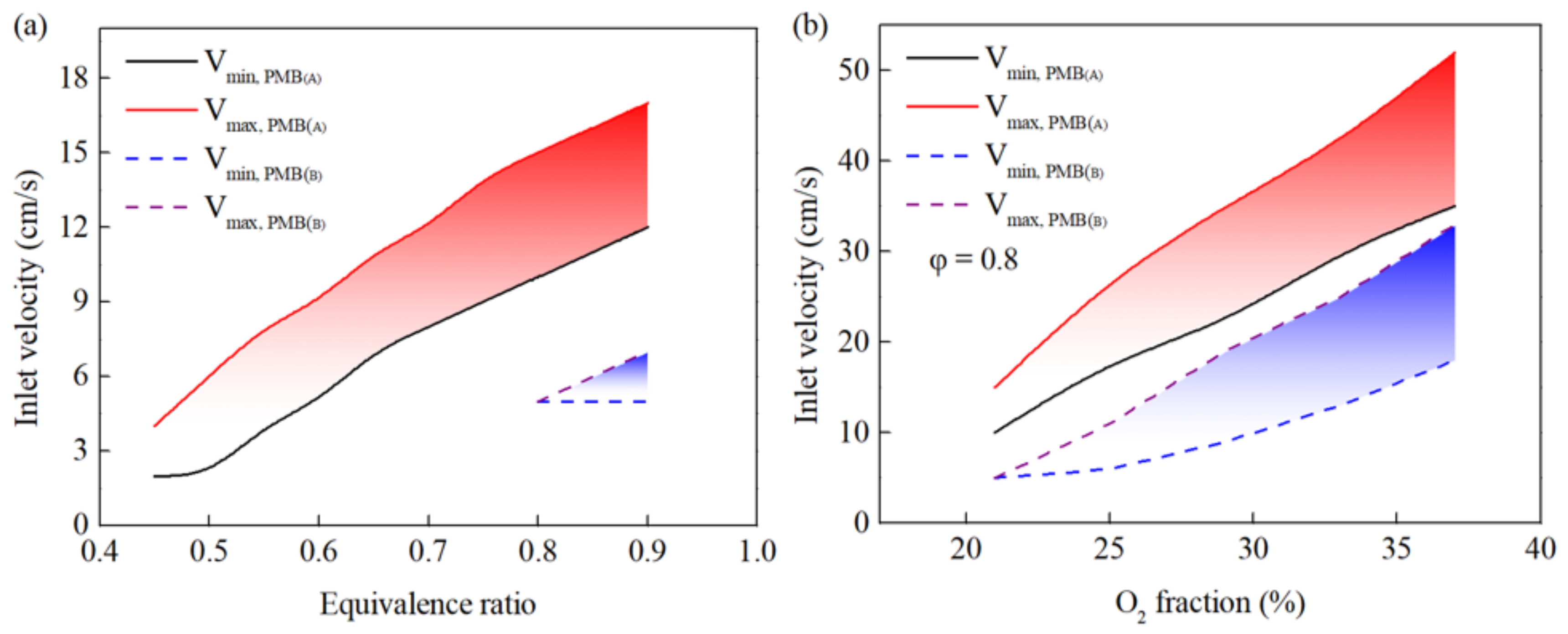
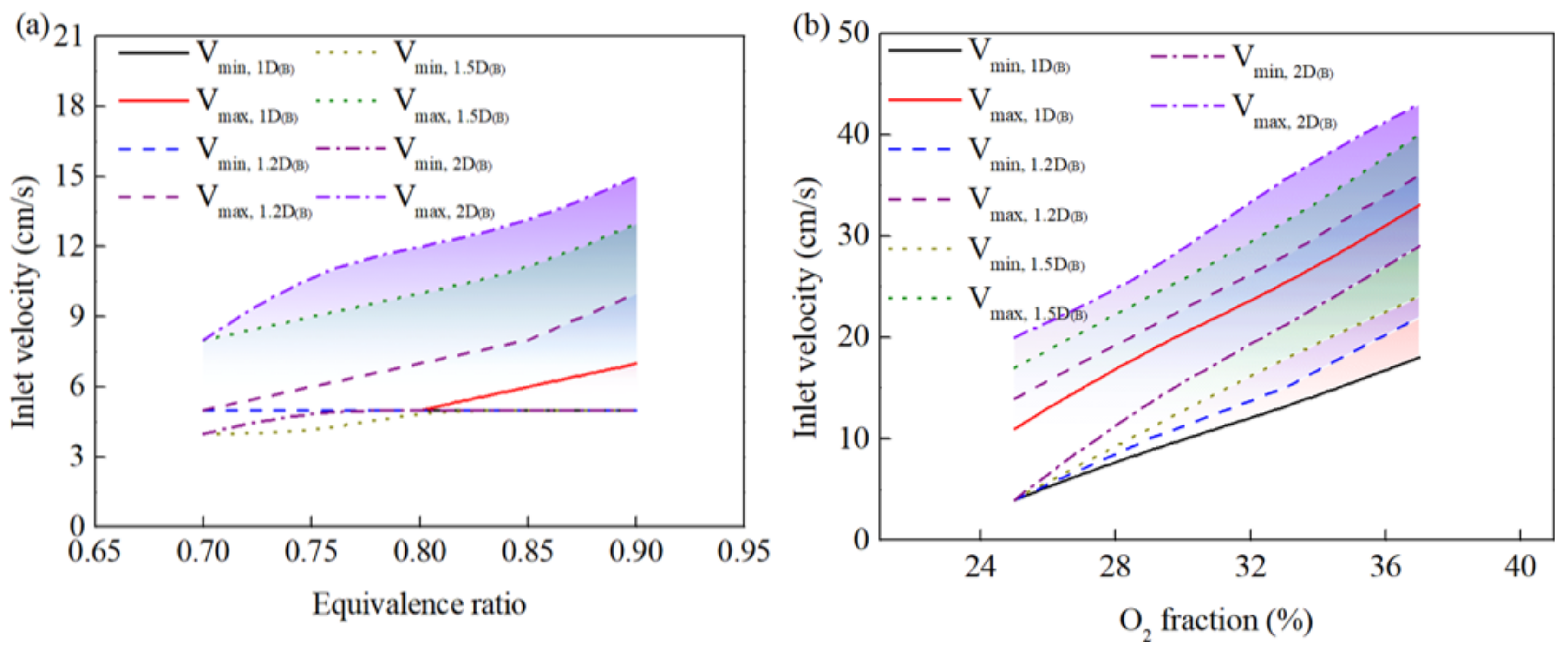
where hf = 5 W/(m2·K) is the convective heat transfer coefficient between the burner wall and the environment, and ω is the emissivity of the wall. When the heat loss of the wall is taken into account, the combustion behavior changes significantly. In Figure 5, the comparison of the stable range of PMB(A) and PMB(B) is shown. In the calculation and experiment of PMB(B), the combustion phenomenon with an equivalence ratio of less than 0.8 while the O2 fraction was 21% was not found. The burner cannot be ignited or burned steadily since the flame front will gradually move downstream and blow out. This situation is more prominent in PMB(C), which cannot be sustained even when the equivalence ratio is less than 1. The comparison with PMB(A) under the condition of an equivalence ratio of 0.8 is shown in Figure 6. Unfortunately, the stable range was also observed to be extremely narrowed for both burners under successful ignition conditions. Under the condition that the combustion can be maintained, the stable range of PMB(B) is reduced by 40–60% on average compared with that of PMB(A), while that of PMB(C) is 60–80%.
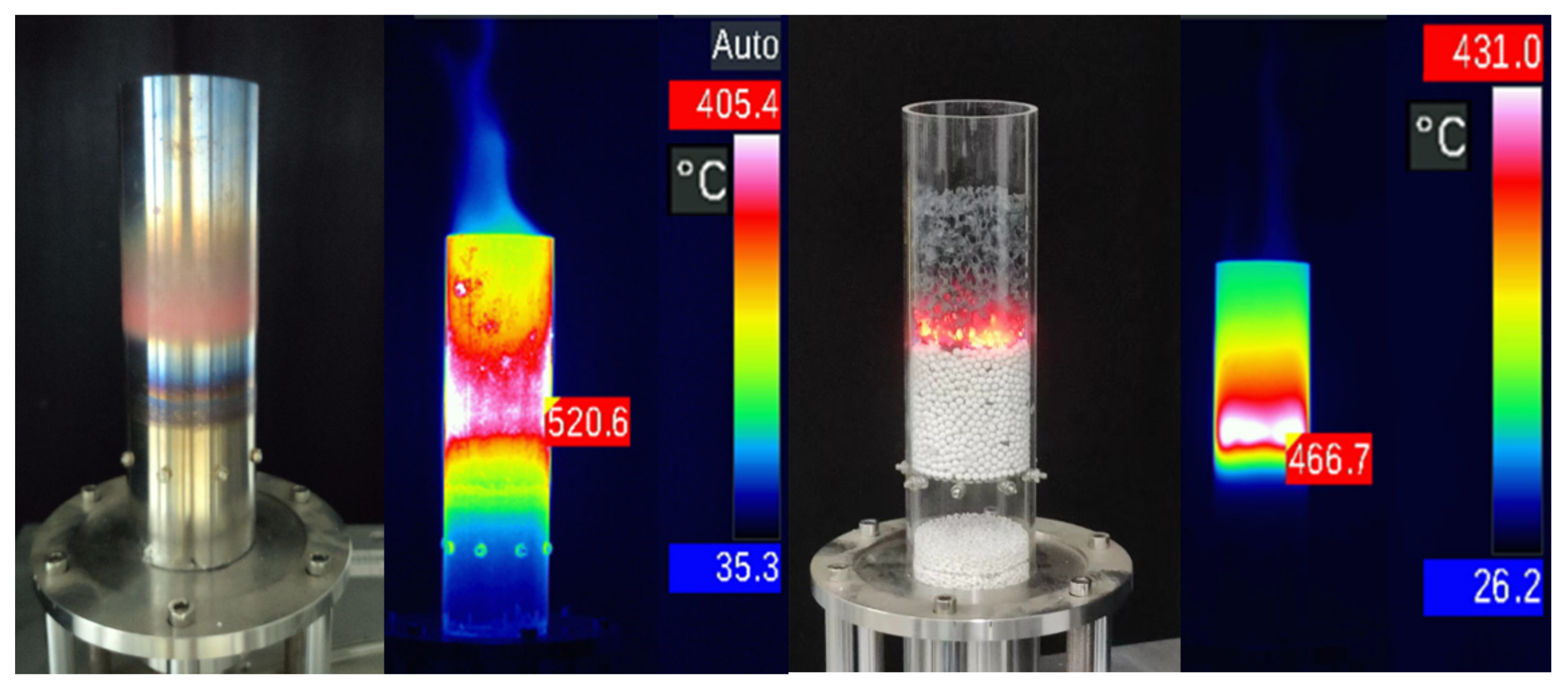
As mentioned previously, the effect of the inlet velocity on the combustion temperature is not remarkable in PMB(A). This feature is also consistent for PMB(B) and PMB(C), since heat loss does not significantly affect the temperature at the center of the burner. For example, the corresponding peak temperature difference between Vmax and Vmin is 130 K under the condition of φ = 0.8 and O2 = 37% Vol. The most remarkable difference is the flame front presents an apparent two-dimensional shape after considering the heat exchange between the wall and the environment. Figure 7 shows the temperature fields of PMB(B) and PMB(C) when the equivalence ratio is 0.8, and the O2 fraction is 25%. The wall temperature captured with the thermal imaging system under the same conditions is revealed in Figure 8. For PMB(C), the wall temperature is replaced by SiC foam and packed bed temperature near the wall. The results show that the peak wall temperature of PMB(B) is 110 K higher than that of PMB(C), and the estimated heat loss according to Equation (28) of the two burners account for 36.2% and 44.7% of the heat load. As a result, after considering heat loss, the wall temperature is about 300 K lower than that of PMB(A).
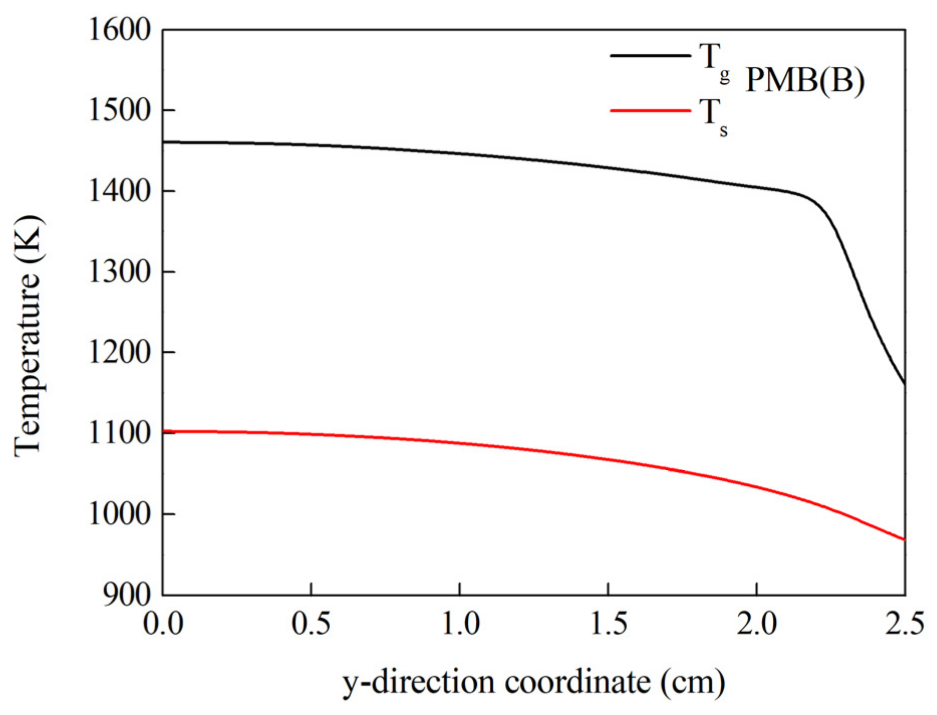
Due to the heat loss, the temperature of the solid matrix near the wall is lower than that near the center of the burner. When the premixed gas near the center of the burner reaches the ignition temperature, the heat released by reactions will transfer to the wall. The premixed gas closer to the wall needs more residence time to reach the ignition temperature, and the ignition position will be closer to the downstream. If the velocity of premix gas increases, the angle of the inclination of the flame front will be larger. When the unburnt gas reaches the burner outlet before reaching the ignition temperature or the flame front is broken off, the phenomenon of fuel leakage or even blow-out will occur. At the same time, the temperature decrease at the burner wall causes the flame propagation speed to slow down, which also aggravates the inclination of the flame front. This is also one of the reasons why the stable combustion range of the burner is narrowed. It can be seen from the temperature distribution at the interface (Figure 9) that the heat loss results in a significant decrease in Tg and Ts values near the wall, which may be lower than the ignition temperature of the fuel, leading to a blow-out. This means that a higher flame temperature is required to maintain stable combustion after considering heat loss. It was observed that under adiabatic conditions, combustion stability was challenging to maintain at peak temperatures below 1100 K. However, this value was 1450 K in PMB(B) and PMB(C).
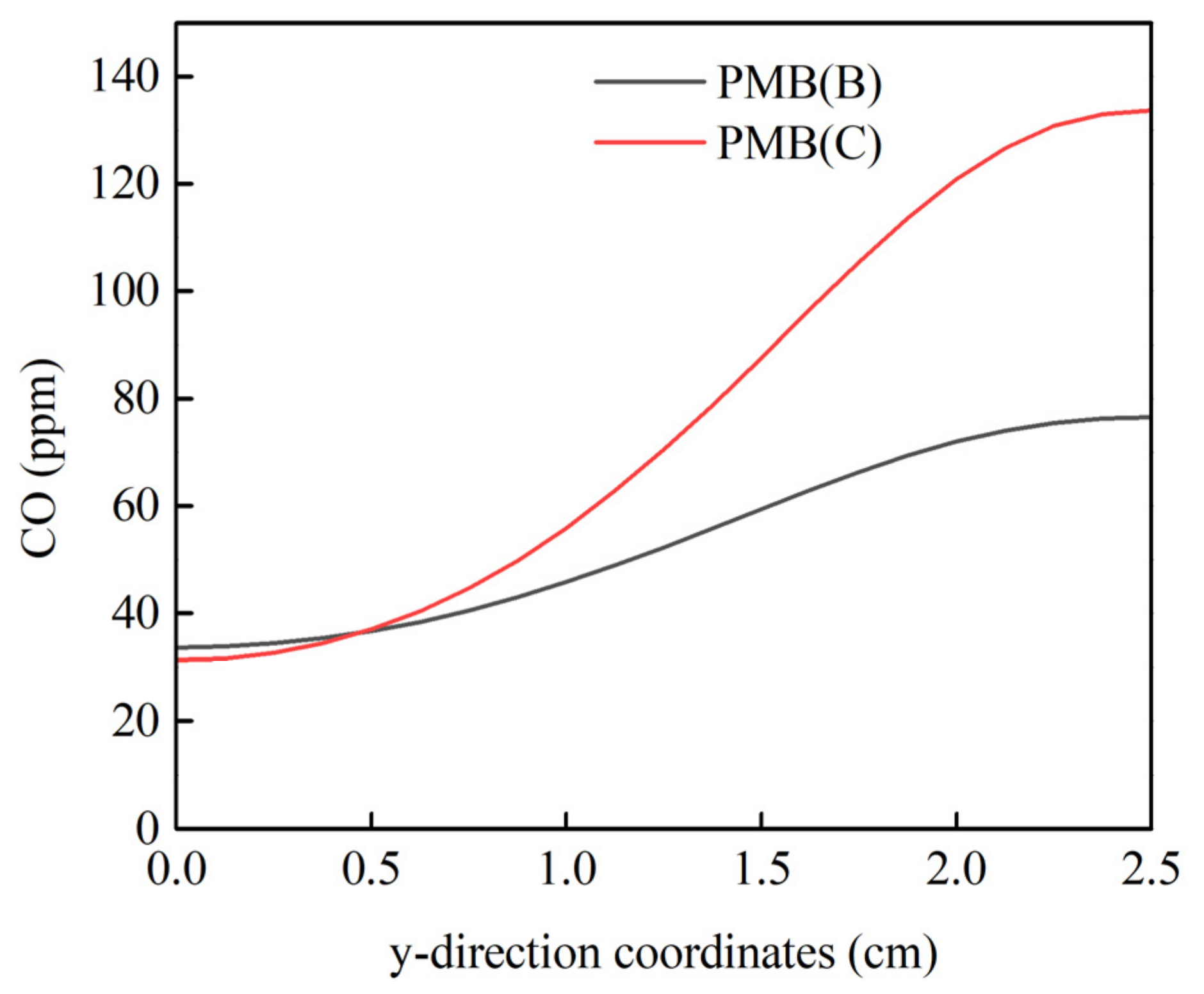
According to the CO emissions in Table 2, it can be found that the CO emissions of the burner under adiabatic conditions are extremely low. After accounting for heat loss, the decrease in temperature at the wall reduces the oxidation rate of CO, resulting in incomplete combustion. The CO emissions of PMB(B) and PMB(C) are enormous in some cases in which the peak temperature is lower than 1450 K. Especially for PMB(C), it exceeds 10,000 ppm. Figure 10 reveals the CO mole fraction at the outlet, and the operating parameters are the same as those in Figure 9. Clearly, the CO concentration near the wall is much greater than that at the center of the burner. One of the reasons is that the ignition of premixed gas near the wall is delayed, and the residence time of exhaust gas is shorter than that near the center of the burner. On the other hand, the temperature of exhaust gas near the wall is reduced due to heat loss, which slows down the oxidation rate of CO. This phenomenon will improve with the increase in combustion temperature. For example, when the equivalence ratio is 0.8, and the O2 fraction is 33%, the combustion temperature reaches about 2000 K, and the average CO emission at the outlet decreases to less than 20 ppm for PMB(C).

3.3. Effect of Burner Diameter on Combustion Behavior

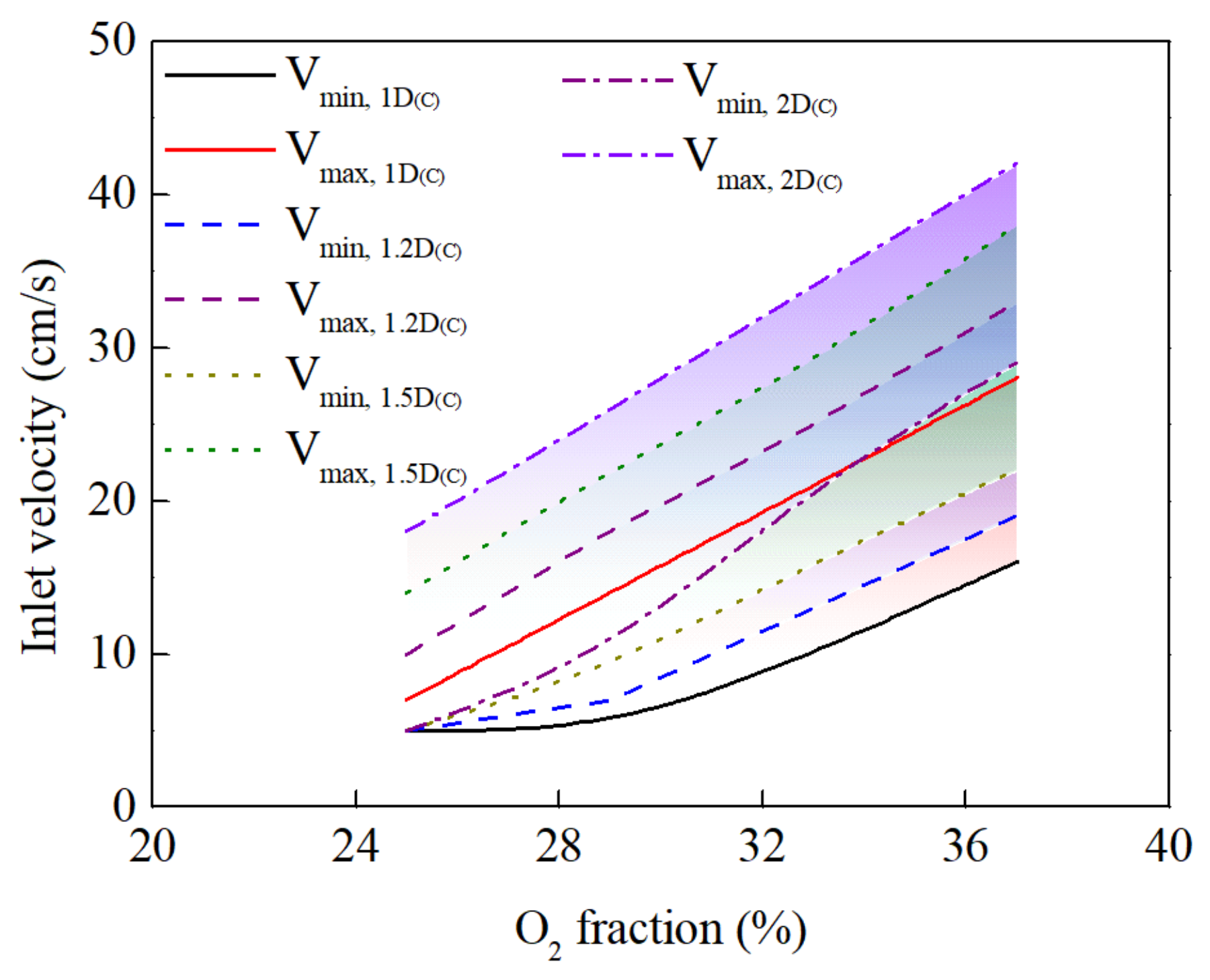
In this work, it was observed that after the flame temperature is lower than 1450 K, the situation of blow-off, as well as CO emission, will increase significantly. Therefore, ensuring that the flame temperature is still higher than 1450 K after considering the heat loss is one of the methods to maintain flame stability. Increasing the insulation layer to reduce heat loss is the most cost-effective way. Since radiation may be required in some application environments, this method therefore has limitations. Increasing the heat load is another appreciable method. It is practical to increase the equivalence ratio or O2 fraction, but as revealed in Figure 5, the stable range is extremely narrow compared with the adiabatic condition. As a result, the burner’s dynamic power load adjustment range is also significantly reduced. Another way to increase the heat load is to increase the cross-sectional area of the burner, that is, the pipe diameter. We evaluated the cases where the pipe diameter was enlarged by 1.2, 1.5, and 2 times, respectively. The 1.2D, 1.5D, and 2D mentioned below represent the ratio of the diameter of the burner to that of the original. The corresponding stable ranges are shown in Figure 11 and Figure 12. It can be seen that with the increase of the burner diameter, the stable range gradually wides and approaches the result of PMB(A). When the heat load increases, more heat can be supplied to the burner to resist heat loss on the wall. Here, we define η (= hloss/hload) as the ratio of heat loss (hloss) to heat load (hload). As the burner diameter increases, the η gradually decreases, and more heat can remain in the burner. Under the conditions of Figure 7, when the diameter is 2D, the η of PMB(B) and PMB(C) are reduced to 21.7% and 21.9%, respectively. Therefore, the peak temperature gradually increases and becomes closer to the temperature of PMB(A). Specificlly, the Tg peak temperature increased by about 80 K, while the peak temperature of wall increased by about 300 K.
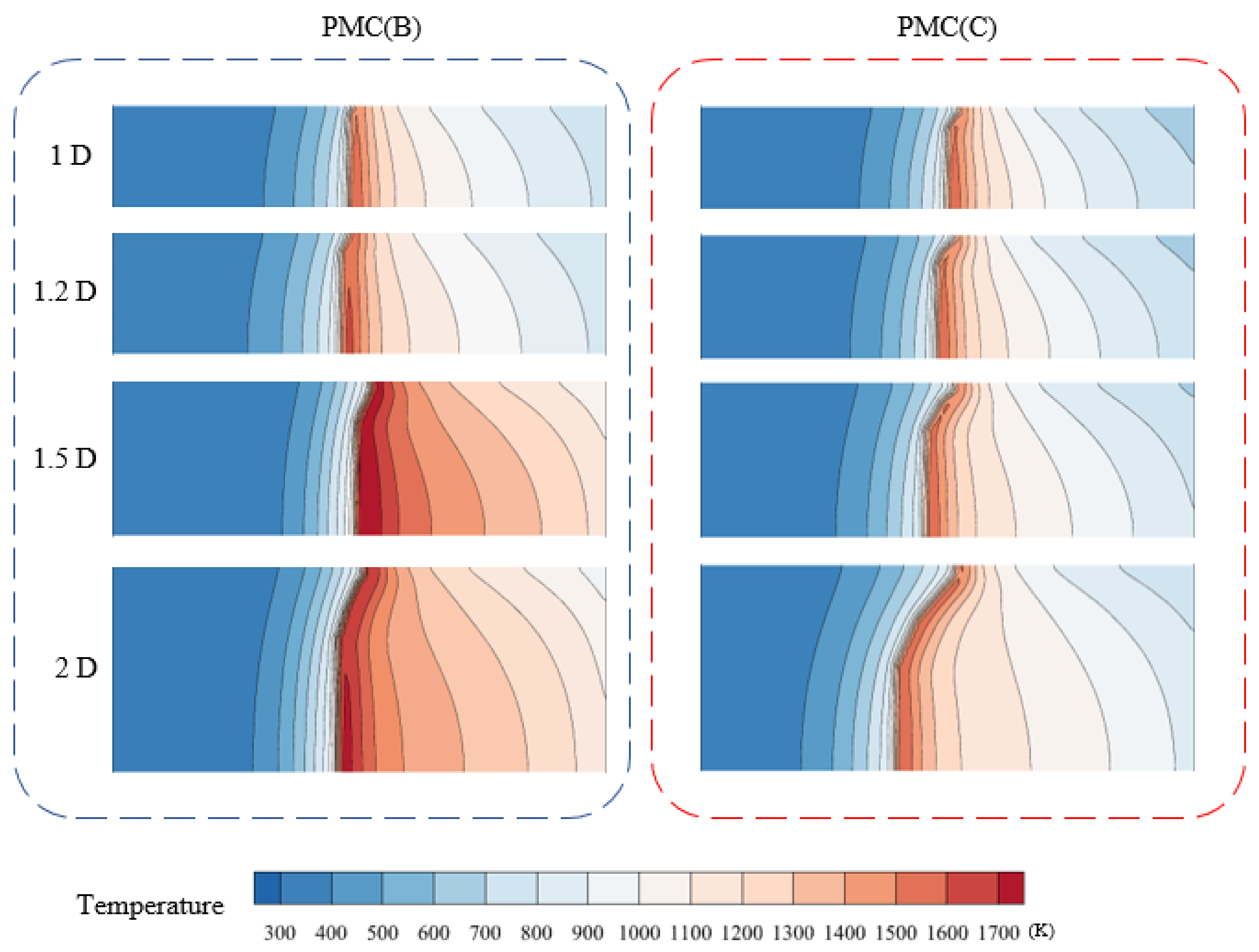
Figure 13 shows the temperature field of the burners with different diameters (φ = 0.8, O2 = 25%, and Vin = 7 cm/s). It can be clearly seen that as the diameter of the burner increases, the flame temperature increases gradually, but at the same time, the inclination of the flame front increases. As the burner diameter increases, the wall area increases, resulting in more heat loss, which promotes flame inclination, but has little influence on the propagation velocity [44]. In addition, Figure 14 depicts the temperature field when the flame front positions are in the preheating zone and the combustion zone, respectively. It can be seen that the flame front located in the combustion zone is more likely to be inclined. It can be explained as follows: in the preheating zone, the porous medium material with minor porosity leads to large flow resistance, and the heat transfer rate between solid and gas is higher at a small pore size. The heat release of the chemical reaction at the center of the burner can be rapidly transferred to the burner wall in a thermally conductive manner through the solid matrix. Therefore, the phenomenon of the inclination of the flame front is difficult to occur when the diameter of the burner is small. On the contrary, the heat transfer resistance between the solid matrix and gas phase in the combustion zone increases so that the heat at the center of the burner is more difficult to supplement the heat loss at the wall, resulting in poor temperature uniformity. At the same time, another consequence of this phenomenon is that the CO emissions will be higher when the flame front is located in the combustion zone than in the preheating zone.
With the increase of the diameter of the burner, the area of the flame front becomes larger, and the heat load increases so that the stable range is broadened. The heat loss of the quartz glass tube is the worst case of thermal insulation, but it can be seen that the stable range is 29–42 cm/s of PMB(C), which is close to PMB(B) (29–43 cm/s) when the burner diameter increases to 10 cm. It can be concluded that the influence of the boundary effect on the stable range gradually weakens with the increase of the diameter of the burner. When the diameter of the burner is larger than 10 cm, the reduction of the stable range caused by the heat loss is negligible.
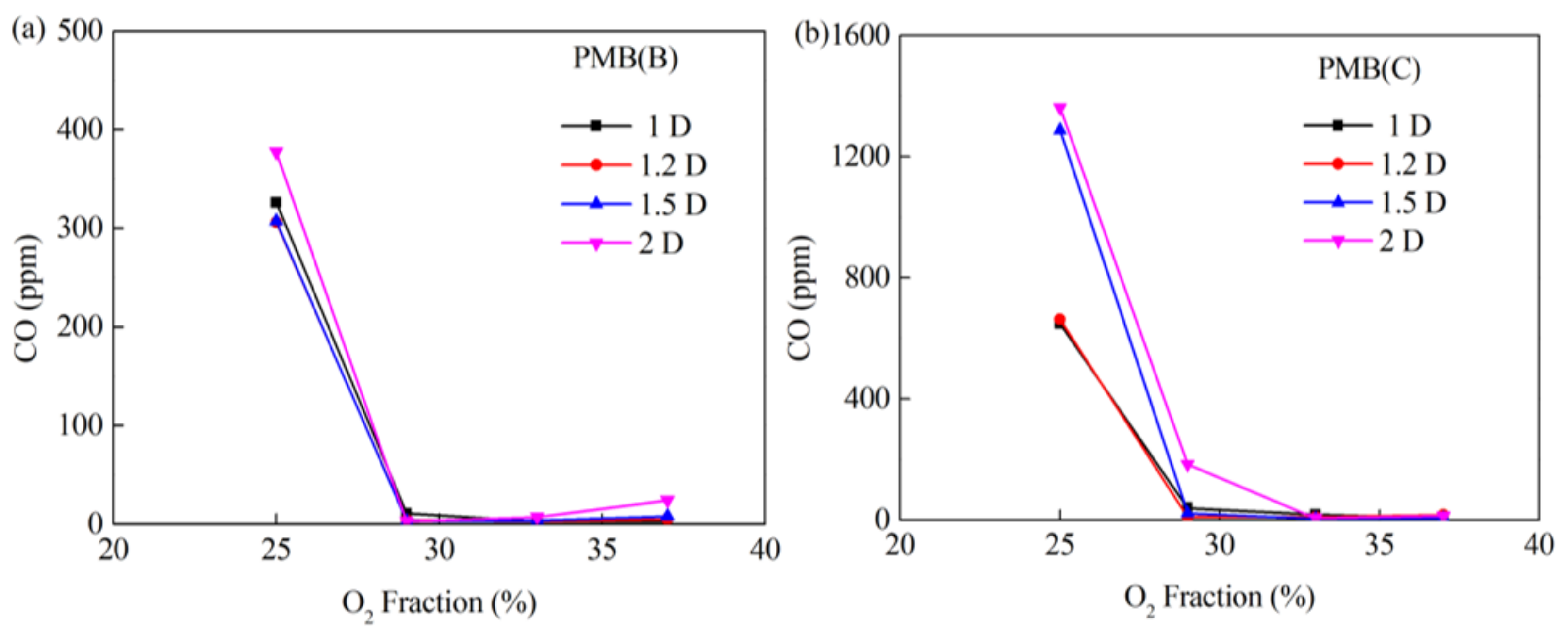
As mentioned earlier, CO emissions are related to combustion temperature and residence time. Since the burner diameter can affect the combustion temperature, it can infer that the CO emissions will also be related to the diameter. Figure 15 shows that the average CO fraction distribution at the outlet varies with burner diameter. The most remarkable result is that the increase in burner diameter is not conducive to CO emission. As the diameter of the burner increases, the heat loss at the wall increases, but the heat near the center of the burner is difficult to supplement quickly. As a result, the inclination of the flame increases, and the ignition of unburned gas near the wall is more delayed. This is more pronounced when the combustion temperature is low. When the O2 fraction of PMB(B) reaches 27%, the CO emission will be lower than 100 ppm, and here, the peak temperature is reached at about 1600 K. Since the wall temperature of PMB(C) is lower than that of PMB(B), more oxidant is needed to increase the reaction rate and temperature to provide sufficient oxidation rate for CO near the wall. In general, when the Tg peak temperature is higher than 1600 K, the CO emission will be significantly reduced, but it is still more than 10 times higher than that of PMB(A). When the temperature exceeds 2100 K, the effect of residence time is more significant, and more CO cannot be oxidized in time, resulting in more emissions.

4. Conclusions

In this paper, a radiant two-layer porous media combustion model was established. The walls of the burner are wrapped with three types of thermal insulation materials to present different degrees of heat loss. The effect of heat loss of the burner wall on flame stability and pollutant emissions are studied in detail under oxy-fuel condition. The numerical flame instability agrees well with the results of the experiments. The results reveal that:
(1) In this paper, the heat loss of wall by convection and thermal radiation are considered for medium and high strengths, which account for 36.2% and 44.7% of the thermal power at an equivalence ratio of 0.8 and O2 fraction of 21%, with a burner diameter of 5 cm. When the heat loss is taken into account, the gas and solid phase temperatures near the burner wall are significantly reduced. As a result, the stable range is reduced by more than 50% under the influence of the wall effect compared to the adiabatic condition. At the same time, it also increases the incomplete combustion near the wall, and the CO emission will increase by more than 10 times.
(2) The wall heat loss results in a lower solid matrix temperature near the wall than at the axial center of the burner. Consequently, the premixed gas at the near-wall will be delayed in ignition compared to the center, resulting in a lower flame propagation speed. As a result, the flame at the near wall will be tilted downstream. This phenomenon is more pronounced when the flame front is located in the combustion zone rather than preheating zone.
(3) Increasing the burner diameter has a positive effect on the stable range. Due to the increase in diameter, the proportion of heat loss to heat power decreases, and the combustion process is closer to the adiabatic conditions. Since PMB(C) represents the maximum heat loss condition, the influence of heat loss on the stable range can be ignored when the diameter of the burner increases to 10 cm. Therefore, it is recommended to set the diameter above 10 cm in the design of the cylindrical two-layer porous media burner. It should be noted that the increase in diameter will promote CO emissions. Under conditions where the peak flame temperature reaches above 1600 K (increasing the equivalent ratio or oxidizer ratio), the oxidation rate of CO near the wall is sufficient and results in emissions below 100 ppm. It is important to note that flame temperatures exceeding 2100 K should be avoided.

Author Contributions

Conceptualization: Z.H.; methodology: M.L.; validation: Z.H.; resources: X.X., T.L.C., X.L. and Y.L.; writing—original draft preparation: M.L.; writing—review and editing: Z.H. All authors have read and agreed to the published version of the manuscript.

Funding

This work was financially supported by the National Natural Science Foundation of China [Project No. U22A20127,11572274], The Hong Kong Polytechnic University [Project Nos.: 4-BCD3 and 88Y9].

Data Availability Statement

The authors will provide data and material upon reasonable request.

Conflicts of Interest

The authors declare no conflict of interest.

References

  1. Mostafa, M.M.H.; Liu, R.; Wang, Z.; Chen, H.; Yang, J.; Manickam, S. Study on the Effect of Standardization on Energy Demand and Economic Growth. E3S Web Conf. 2021, 261, 01018. [Google Scholar] [CrossRef]
  2. Lei, R.; Feng, S.; Lauvaux, T. Country-scale trends in air pollution and fossil fuel CO2 emissions during 2001–2018: Confronting the roles of national policies and economic growth. Environ. Res. Lett. 2021, 16, 014006. [Google Scholar] [CrossRef]
  3. Wu, F.; Argyle, M.D.; Dellenback, P.A.; Fan, M.H. Progress in O2 separation for oxy-fuel combustion—A promising way for cost-effective CO2 capture: A review. Prog. Energy Combust. Sci. 2018, 67, 188–205. [Google Scholar] [CrossRef]
  4. Zheng, L. Oxy-Fuel Combustion for Power Generation and Carbon Dioxide (CO2) Capture; Woodhead Publishing: Sawston, UK, 2011; pp. 1–13. [Google Scholar]
  5. Habib, M.A.; Badr, H.M.; Ahmed, S.F.; Ben-Mansour, R.; Mezghani, K.; Imashuku, S.; la O’, G.J.; Shao-Horn, Y.; Mancini, N.D.; Mitsos, A. A review of recent developments in carbon capture utilizing oxy-fuel combustion in conventional and ion transport membrane systems. Int. J. Energy Res. 2011, 35, 741–764. [Google Scholar] [CrossRef]
  6. Mao, Z.; Zhang, L.; Zhu, X.; Zheng, C. Experiment investigation of coal MILD-Oxy combustion integrated with flue gas recirculation at a 0.3 MW th furnace. Fuel Process. Technol. 2017, 162, 126–134. [Google Scholar] [CrossRef]
  7. Yin, C. Prediction of air-fuel and oxy-fuel combustion through a generic gas radiation property model. Appl. Energy 2017, 189, 449–459. [Google Scholar] [CrossRef]
  8. Peng, Q.; Jiaqiang, E.; Chen, J.; Zuo, W.; Zhao, X.; Zhang, Z. Investigation on the effects of wall thickness and porous media on the thermal performance of a non-premixed hydrogen fueled cylindrical micro combustor. Energy Convers. Manag. 2018, 155, 276–286. [Google Scholar] [CrossRef]
  9. Mathis, W.M.; Ellzey, J.L. Flame stabilization, operating range, and emissions for a methane/air porous burner. Combust. Sci. Technol. 2003, 175, 825–839. [Google Scholar] [CrossRef]
  10. Sanmiguel, J.E.; Mehta, S.A.; Moore, R.G. An Experimental Study of Controlled Gas-Phase Combustion in Porous Media for Enhanced Recovery of Oil and Gas. J. Energy Resour. Technol. 2003, 125, 64–71. [Google Scholar] [CrossRef]
  11. Keramiotis, C.; Founti, M.A. An experimental investigation of stability and operation of a biogas fueled porous burner. Fuel 2013, 103, 278–284. [Google Scholar] [CrossRef]
  12. Akbari, M.H.; Riahi, P.; Roohi, R. Lean flammability limits for stable performance with a porous burner. Appl. Energy 2009, 86, 2635–2643. [Google Scholar] [CrossRef]
  13. Zangeneh, V.; Alipoor, A.; Lund, H.; Kaiser, M.J. Stability study of hydrogen-air flame in a conical porous burner. Energy 2021, 215, 119140. [Google Scholar] [CrossRef]
  14. Fruzza, F.; Lamioni, R.; Tognotti, L.; Galletti, C. Flashback of H2-enriched premixed flames in perforated burners: Numerical prediction of critical velocity. Int. J. Hydrogen Energy 2023, in press. [Google Scholar] [CrossRef]
  15. Gao, H.B.; Qu, Z.G.; Feng, X.B.; Tao, W.Q. Combustion of methane/air mixtures in a two-layer porous burner: A comparison of alumina foams, beads, and honeycombs. Exp. Therm Fluid Sci. 2014, 52, 215–220. [Google Scholar] [CrossRef]
  16. Gao, H.B.; Qu, Z.G.; Feng, X.B.; Tao, W.Q. Methane/air premixed combustion in a two-layer porous burner with different foam materials. Fuel 2014, 115, 154–161. [Google Scholar] [CrossRef]
  17. Shi, J.; Mao, M.; Li, H.; Liu, Y.; Liu, Y.; Deng, Y. Influence of Chemical Kinetics on Predictions of Performance of Syngas Production From Fuel-Rich Combustion of CO2/CH4 Mixture in a Two-Layer Burner. Front. Chem. 2019, 7, 902. [Google Scholar] [CrossRef]
  18. Arrieta, C.E.; García, A.M.; Amell, A.A. Experimental study of the combustion of natural gas and high-hydrogen content syngases in a radiant porous media burner. Int. J. Hydrogen Energy 2017, 42, 12669–12680. [Google Scholar] [CrossRef]
  19. Coutinho, J.E.A.; de Lemos, M.J.S. Laminar flow with combustion in inert porous media. Int. Commun. Heat Mass Transf. 2012, 39, 896–903. [Google Scholar] [CrossRef]
  20. Hashemi, S.M.; Hashemi, S.A. Flame stability analysis of the premixed methane-air combustion in a two-layer porous media burner by numerical simulation. Fuel 2017, 202, 56–65. [Google Scholar] [CrossRef]
  21. Pan, J.F.; Yu, H.; Ren, H.M.; Zhang, Y.; Lu, Q.B.; Quaye, E.K. Study on combustion characteristics of premixed methane/oxygen in meso-combustors with different cross-sections. Chem. Eng. Process. -Process Intensif. 2020, 154, 108025. [Google Scholar] [CrossRef]
  22. Ahmed, P. Characteristics of air and oxy-fuel combustion in micro-channels. In Proceedings of the HEFAT2012 9th International Conference on Heat Transfer, Fluid Mechanics and Thermodynamics, St. Julian’s, Malta, 16–18 July 2012. [Google Scholar]
  23. Habib, R.; Yadollahi, B.; Saeed, A.; Doranehgard, M.H.; Karimi, N. On the Response of Ultralean Combustion of CH4/H2 Blends in a Porous Burner to Fluctuations in Fuel Flow-an Experimental Investigation. Energy Fuels 2021, 35, 8909–8921. [Google Scholar] [CrossRef] [PubMed]
  24. Qiu, K.; Hayden, A. Premixed gas combustion stabilized in fiber felt and its application to a novel radiant burner. Fuel 2006, 85, 1094–1100. [Google Scholar] [CrossRef]
  25. Chou, S.K.; Yang, W.M.; Li, J.; Li, Z.W. Porous media combustion for micro thermophotovoltaic system applications. Appl. Energy 2010, 87, 2862–2867. [Google Scholar] [CrossRef]
  26. Gentillon, P.; Southcott, J.; Chan, Q.N.; Taylor, R.A. Stable flame limits for optimal radiant performance of porous media reactors for thermophotovoltaic applications using packed beds of alumina. Appl. Energy 2018, 229, 736–744. [Google Scholar] [CrossRef]
  27. Peng, Q.; Yang, W.; Jiaqiang, E.; Xu, H.; Li, Z.; Yu, W.; Tu, Y.; Wu, Y. Experimental investigation on premixed hydrogen/air combustion in varied size combustors inserted with porous medium for thermophotovoltaic system applications. Energy Convers. Manag. 2019, 200, 112086. [Google Scholar] [CrossRef]
  28. Xie, M.Z.; Shi, J.R.; Deng, Y.B.; Liu, H.; Zhou, L.; Xu, Y.N. Experimental and numerical investigation on performance of a porous medium burner with reciprocating flow. Fuel 2009, 88, 206–213. [Google Scholar] [CrossRef]
  29. Liao, M.; Jia, S.; Wang, Q.; Chan, T.L.; Li, Y.; Xu, X.; He, Z. Numerical Simulation of Methane Combustion in Two-Layer Porous Media Under Oxy-Fuel Condition. Flow Turbul. Combust. 2022, 110, 649–670. [Google Scholar] [CrossRef]
  30. Zheng, C.; Cheng, L.; Saveliev, A.; Luo, Z.; Cen, K. Gas and solid phase temperature measurements of porous media combustion. Proc. Combust. Inst. 2011, 33, 3301–3308. [Google Scholar] [CrossRef]
  31. Banerjee, A.; Paul, D. Developments and applications of porous medium combustion: A recent review. Energy 2021, 221, 119868. [Google Scholar] [CrossRef]
  32. Yakovlev, I.; Zambalov, S. Three-dimensional pore-scale numerical simulation of methane-air combustion in inert porous media under the conditions of upstream and downstream combustion wave propagation through the media. Combust. Flame 2019, 209, 74–98. [Google Scholar] [CrossRef]
  33. Ferguson, J.C.; Sobhani, S.; Ihme, M. Pore-resolved simulations of porous media combustion with conjugate heat transfer. Proc. Combust. Inst. 2021, 38, 2127–2134. [Google Scholar] [CrossRef]
  34. Stagni, A.; Frassoldati, A.; Cuoci, A.; Faravelli, T.; Ranzi, E. Skeletal mechanism reduction through species-targeted sensitivity analysis. Combust. Flame 2016, 163, 382–393. [Google Scholar] [CrossRef]
  35. Macdonald, I.F.; El-Sayed, M.S.; Mow, K.; Dullien, F.A.L. Flow through Porous Media-the Ergun Equation Revisited. Ind. Eng. Chem. Fundam 1979, 18, 199–208. [Google Scholar] [CrossRef]
  36. Achenbach, E. Heat flow characterstics of packed beds. Exp. Therm. Fluid Ence 1995, 10, 17–27. [Google Scholar] [CrossRef]
  37. Youngis, B.L.; Viskanta, R. Experimental determination of the volumetric heat transfer coefficient between stream of air and ceramic foam. Int. J. Heat Mass Transf. 1993, 36, 1425–1434. [Google Scholar] [CrossRef]
  38. Dobrego, K.V.; Gnesdilov, N.N.; Lee, S.H.; Choi, H.K. Overall chemical kinetics model for partial oxidation of methane in inert porous media. Chem. Eng. J. 2008, 144, 79–87. [Google Scholar] [CrossRef]
  39. Hsu, P.F.; Howell, J.R. Measurements of thermal conductivity and optical properties of porous partially stabilized zirconia. Exp. Heat Transf. 1993, 5, 293–313. [Google Scholar] [CrossRef]
  40. Cuoci, A.; Frassoldati, A.; Faravelli, T.; Ranzi, E. OpenSMOKE++: An object-oriented framework for the numerical modeling of reactive systems with detailed kinetic mechanisms. Comput. Phys. Commun. 2015, 192, 237–264. [Google Scholar] [CrossRef]
  41. Shi, Y.; Ding, S.; Qiu, T.; Liu, C.; Zhang, S. Bi-Fo time scaling method in the numerical simulation of transient conjugate heat transfer. Propuls. Power Res. 2021, 10, 15. [Google Scholar] [CrossRef]
  42. Maffulli, R.; Marinescu, G.; Li, H. On the Validity of Scaling Transient Conjugate Heat Transfer Characteristics. J. Eng. Gas Turbines Power 2020, 142, 031021. [Google Scholar] [CrossRef]
  43. Chen, X.; Li, J.; Zhao, D.; Rashid, M.T.; Wang, N. Effects of porous media on partially premixed combustion and heat transfer in meso-scale burners fuelled with ethanol. Energy 2021, 224, 120191. [Google Scholar] [CrossRef]
  44. Wang, G.; Tang, P.; Li, Y.; Xu, J.; Durst, F. Flame front stability of low calorific fuel gas combustion with preheated air in a porous burner. Energy 2018, 170, 1279–1288. [Google Scholar] [CrossRef]
Figure 1. Schematic diagram of the experimental device (a); photo of experimental equipment (b).
Processes 11 02182 g001
Figure 2. Burners and porous medium materials used in the experimental system.
Processes 11 02182 g002
Figure 3. Distribution of thermocouples.
Processes 11 02182 g003
Figure 4. Gas-phase temperature at inlet velocities of 7 cm/s and 8 cm/s (φ = 0.6, O2 = 21%).
Processes 11 02182 g004
Figure 5. Comparison of the stable range of PMB(A) and PMB(B) varies with: equivalence ratio (a); O2 mole fraction (b).
Processes 11 02182 g005
Figure 6. Comparison of the stable range of PMB(A) and PMB(C) varies with O2 mole fraction (φ = 0.8).
Processes 11 02182 g006
Figure 7. Temperature field of PMB(B) and PMB(C).
Processes 11 02182 g007
Figure 8. Wall temperature of: left (PMB(B)); right (PMB(C)).
Processes 11 02182 g008
Figure 9. Temperature field of PMB(B) at x = 6 cm (φ = 0.8, O2 = 25%Vol, and Vin = 6 cm/s).
Processes 11 02182 g009
Figure 10. CO emissions of PMB(B) and PMB(C) at the outlet (φ = 0.8, O2 = 25%Vol, and Vin = 6 cm/s).
Processes 11 02182 g010
Figure 11. Stable range of PMB(B) varies with the diameter: equivalence ratio (a); O2 mole fraction (b).
Processes 11 02182 g011
Figure 12. The stable range of PMB(C) varies with the diameter.
Processes 11 02182 g012
Figure 13. Temperature field varies with the burner diameter.
Processes 11 02182 g013
Figure 14. Temperature field at Vin = 19 and 21 cm/s.
Processes 11 02182 g014
Figure 15. Variation in CO emissions with burner diameter: PMB(B) (a); PMB(C) (b).
Processes 11 02182 g015
Table 1. Physical properties of the porous medium material.
PropertyUnitPreheating ZoneCombustion Zone
Densitykg/m339003200
Heat capacityJ/(kg·K)910825
Porosity-0.40.8
Extinction coefficient1/m800234.1
Thermal conductivityW/(m·K)0.280.71
Pore diametermm32.56
Table 2. List of experimental equipment.
EquipmentModelMeasurement RangeError or Uncertainty
Mass flow controllerD07-9E
D07-7B
D07-7B
0~50 SLM for CO2
0~10 SLM for O2
0~5 SLM for CH4
2% F.S.
Gas analyzerTesto350 pro0~10,000 ppm for CO±2 ppm (0~39.9); 5% measured value (40~500 ppm)
ThermocoupleS-type273~1400 K±2.5 K
ThermocoupleK-type233~650 K±2.5 K
Thermal imaging cameraFLUKE TiX660233~1473 K±1.5 K or 1.5%
Thermocouple input modelNI 9214233~1700 K±4.5 K
Table 3. The combustion behavior of PMB(A).
φO2 Fraction
(%)
Vmin
(cm/s)
Vmax
(cm/s)
NumericalExperimentalNumericalExperimental
Tg,vmin
(K)
Tg,vmax
(K)
Tg,vmin
(K)
Tg,vmax
(K)
COvmin (ppm)COvmax (ppm)COvmin (ppm)COvmax (ppm)
0.452124124213662.60.9
0.52126129214331.40.7
0.552148140515330.51.2
0.6215914601574132313810.51.9344
0.652171115581619138014731.04.3162
0.72181215841684142714881.79.883
0.752191416451727141015223.822.925
0.821101516701781154016107.553.0534
0.61724125915012.18.7
0.625914161816981.37.1
0.6291318175918065.719.0
0.63317241903193021.168.9
0.63721292008206255.0197.0
Disclaimer/Publisher’s Note: The statements, opinions and data contained in all publications are solely those of the individual author(s) and contributor(s) and not of MDPI and/or the editor(s). MDPI and/or the editor(s) disclaim responsibility for any injury to people or property resulting from any ideas, methods, instructions or products referred to in the content.