Abstract
A cylindrical plunge grinding process was modeled to investigate nonlinear regenerative chatter vibration. The rotating workpiece was a slender Euler–Bernoulli beam, and the grinding wheel was a rigid body moving towards the workpiece at a very low feed speed. A numerical method was proposed to provide the critical boundaries for chatter-free grinding. It was demonstrated that the intersection set surrounded by these critical boundaries was the chatter-free region for the considered parameters. When these parameters were outside of the chatter-free region, the stable grinding process underwent a supercritical Hopf bifurcation, resulting in the loss of the chatter-free behavior and the emergence of periodic chatter motions. Then, the periodic motions of both the grinding wheel and the workpiece were predicted analytically using the method of multiple scales, showing the effect of the regenerative force on the grinding process. We demonstrated that the analytical prediction was valid since it agreed with the numerical simulation. The results showed that there exist three kinds of nonlinear chatter motion, with different amplitudes and mode frequencies.
1. Introduction
Grinding plays a significant role in the manufacturing industry, especially for surface finishing. Due to the increasing automotive applications in the industry, the adoption of high-efficiency grinding technologies is facing many new challenges [1]. Regenerative chatter, as a kind of vibration with a small amplitude and high frequency, exists widely in all kinds of machining processes [2,3]. To design a chatter-free grinding process with maximum workpiece quality, a minimum machining time, and high economic efficiency, the complex relationships between the system parameters and the dynamical behaviors of the process should be shown explicitly [2]. Starting with Altintas [3], many scholars have shown interest in both externally and internally excited vibration in the grinding process. Externally excited vibration is mainly caused by the imbalance or eccentricity of the grinding wheel, and it can be easily eliminated by removing the excitation source derived from the imbalance or eccentricity of the grinding wheel. Internally excited vibration, also called regenerative chatter, is induced by the regenerative effects on the surfaces of both the workpiece and the grinding wheel [4], which result from certain physical parameters of the grinding system. Since regenerative chatter vibration always induces poor surface quality [5], it is necessary to study the relationship between the dynamical behaviors and the physical parameters of the grinding system in order to eliminate such vibrations.
It has been realized that the occurrence of grinding chatter is a kind of doubly regenerative vibration [5,6]. Unlike the turning [7,8] or milling [9,10] processes, which involve a single time delay from the regeneration of the workpiece, the dynamic behavior of the grinding process is affected by two distinct time delays induced by the regenerative effects on the surfaces of both the workpiece and the wheel. An experimental analysis of grinding chatter with a single delay representing wheel regeneration was presented by Jiang, Guo, and Li [11], revealing high-frequency tool–workpiece chatter in grinding operations. Alternatively, time-domain simulations involving geometrical interactions between the grinding wheel and the workpiece were used by Yuan, Järvenpää, Keskinen, and Cotsaftis [12], as well as Li and Shin [13], to investigate many critical characteristics, including chatter regions.
Besides experimental and numerical studies, some constructive theoretical works have also been developed for regenerative chatter analysis. Instead of Laplace transform, Thompson [14] proposed an alternative method to analyze the stability of the steady-state response of the plunge grinding process with wear on both the grinding wheel and the workpiece. The exponential growth in the grinding force was regarded as an index of chatter, and the effects of the grinding wheel speed, workpiece speed, contact stiffness, and wave filtering on the grinding stability were discussed. For a case in which the contact force between the grinding wheel and the workpiece was time-varying, the grinding process was modeled by Yuan, Järvenpää, Keskinen, and Cotsaftis in a system of functional differential equations [12], since Thompson’s consideration failed to produce a model. In this work, the regenerative force was represented as a function of the cutting depth determined by the differences in the current and previous relative positions between the workpiece and the wheel, resulting in time-delayed regenerative force. This dynamic model was then simplified by Liu [15], given the two delays introduced by the double regenerative effects, with the stability information obtained by numerically calculating eigenvalues. When the delayed system under consideration lost its stability, the onset of the chatter vibration in the grinding process was the major concern of these researchers. Such chatter is related not only to the nonlinearity of the beam, but also to the differences in the current and previous relative positions, i.e., the time delay. To predict the nonlinear chatter motions, many analytical methods, such as an incremental perturbation scheme [16], central manifold reduction [17], and the method of multiple scales [18], are applicable. For example, Chung and Liu [19] studied the cylindrical transverse grinding chatter with nonlinear contact force using an incremental perturbation scheme (IPS), while Nayfeh, Chin, and Pratt [20] studied nonlinear turning chatter using the method of multiple scales.
To investigate the effects of regeneration on the stability of a cylindrical plunge grinding process, the contact stiffness and the rotation speeds of both the workpiece and the grinding wheel, which lead to the delays mentioned above, were considered as design parameters in this paper. Based on the aforementioned regenerative force models, we first proposed a dynamic model of the cylindrical plunge grinding process, where the workpiece was taken as a damped hinged–hinged slender Euler–Bernoulli beam and the grinding wheel a damped spring–mass system. Then, the Galerkin technique was applied to decompose the workpiece modes, with only the first-order mode kept to represent the major property of the regenerative chatter. The model was then linearized in the vicinity of the system’s equilibrium in order to study the cutting stability. With the Newton–Raphson method employed for the numerical calculation of the eigenvalues, a parametric continuation algorithm was also proposed to automatically generate initial guesses for parameter iteration [21,22]. As a result, critical boundaries for marginal stability in the parameter space were obtained, the union of which determined the stability boundaries dividing the chatter and chatter-free regions. For the parameters located outside of the chatter-free region, regenerative chatter vibration occurred during the grinding process. To predict the nonlinear chatter motions of the grinding process, the method of multiple scales was then employed to express the relationship between the chatter and the parameters mentioned above in an analytical form. It was found that the analytical prediction agreed well with the numerical simulation, which verified the theoretical investigations. The results showed that a soft grinding wheel should always be the primary choice in most work conditions for chatter avoidance. Nonetheless, the rotation speeds of the workpiece and the grinding wheel can be alternated as well for chatter-free motion when the contact stiffness is too great.
The primary motivation of this study is to propose a full algorithm for the study of stability and nonlinear chatter in the grinding processes, which involves two distinct time delays. Since the eigen equations are transcendental, without analytical solutions, a continuation algorithm with a procedure generating an initial guess is proposed. Moreover, the method of multiple scales in vector form is adopted for the analysis of grinding chatter once the stability has been lost. As a result, the motions of both of the wheel and the workpiece can be revealed to present the dynamic characteristic of grinding chatter, which yields various chatter frequencies and almost asynchronized motions.
2. Materials and Methods
2.1. Dynamic Model of the Cylindrical Plunge Grinding Process
Grinding operation is a kind of machining process which is usually adopted as a finishing process to achieve fine surface quality. In a cylindrical grinding process, the workpiece surface is abraded by a rotating grinding wheel, while the part is rotating and the wheel is moving toward the workpiece for feeding [23]. Unlike the turning or milling processes, in which only the part surface is regenerated, the surface of the grinding wheel is also renewed when the machine works due to the special structure of the wheel, which is a combination of abrasive grains and bond material [24].
A cylindrical plunge grinding process is modeled as a hinged–hinged slender Euler–Bernoulli beam coupled with a damped spring–mass system where the beam represents the workpiece being processed and the grinder fixed to a grinding machine, as shown in Figure 1. The workpiece rotates for a constant angular speed , and the grinding wheel rotates as well for another constant angular speed while it is plunged into the workpiece in its radial direction for a low feed speed . Therefore, the workpiece and wheel displacements, xg and xw, are governed by the following equation [25,26].
where is due to the hinged–hinged workpiece constraints; is a Dirac function; and is the regenerative force, explained in detail in Figure 2.
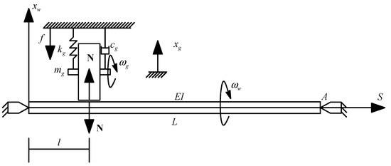
Figure 1.
Schematic of a cylindrical plunge grinding process.
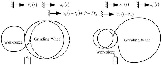
Figure 2.
Regenerative effects on the surfaces of both the workpiece and the grinding wheel.
It can be seen that the instantaneous chip thickness for cutting involves the feed and the regeneration of both workpiece and wheel surfaces. The corresponding cutting force is regarded as proportional to the depth of the cut, so the force involving surface regeneration is called regenerative force. For the wheel regeneration , it is related not only to the current position , but also to the previous position . This is similar to the workpiece regeneration . Thus, the regenerative force is modeled by the following equation [27].
where is the contact stiffness and and are the time delays for the workpiece and the grinding wheel rotating once, respectively. Letting and represent the angular speeds of the workpiece and grinding wheel, the time delays are given by and [6,7,8,9,10].
The model in Figure 1 has simply-supported boundary conditions, given as follows:
In general, the dynamical behavior of the first mode for the beam is the most important. To this end, the displacement of the workpiece is expressed as:
for the boundary condition. Substituting Equations (2) and (4) into Equation (1) and applying Galerkin projection, one obtains the following:
where the linear viscous damping term is added with as the damping coefficient [28].
As a special case, we consider a situation in which the grinding wheel is located at the middle of the workpiece . By defining a state vector given by
choosing the characteristic length and time , and inducing the nondimensional parameters
one transforms Equation (5) into a dimensionless matrix form, given by
where
and is a small dimensionless coefficient. This is a typical multi-dimensional nonlinear dynamic system [28,29,30].
Now, the mathematical model can be obtained as shown in Equation (8). We intend to study the effect of regenerative force on grinding stability by considering the relations between the stability of the trivial equilibrium and physical parameters such as , , and , which are related to regenerative force, as described in the following section.
2.2. A Continuation Algorithm for Chatter Boundaries
Chatter vibration is induced by regenerative force, and a chatter-free grinding process is always required to ensure high surface quality [5]. It is necessary to predict the chatter-free regions in the physical parameter space. The chatter-free grinding process requires the stable trivial equilibrium of Equation (8), which is determined by the signs of the real parts of eigenvalues. It is a critical situation for marginal stability when the real parts are equal to zero. However, it is difficult to obtain the eigenvalues of Equation (8), since it is a delayed differential equation with infinite eigenvalues.
2.2.1. Algebraic Equations of Boundaries
To determine the eigenvalues of Equation (8), one uses the following characteristic matrix [31]
and the corresponding characteristic equation
where det M is the determinant of M. Substituting Equations (9) and (10) into Equation (11) yields:
where () represents the eigenvalues of Equation (8) [32,33]. As mentioned above, the chatter boundary may be determined by . Substituting into Equation (11) and separating the real and imaginary parts, one obtains:
and
It is impossible to determine the roots of Equations (13) and (14) analytically, since they are transcendent equations. Thus, a numerical method will be employed to successively obtain the roots of Equations (13) and (14) with varying parameters.
2.2.2. Continuation Algorithm
In this subsection, the Newton–Rapson method (NRM) is considered as a basic tool for the computation of eigenvalues. Meanwhile, a continuation algorithm (CA) is given to locate the critical boundaries by obtaining the critical values successively with the parameter varying. This is key to giving an initial guess when one uses the NRM in searching for numerical solutions. With the parameter varying, one will always be faced with a choice of the initial values for the parameter iteration at each step. To give a proper initial guess so that the parameters can be iterated, the CA is established and schemed in Figure 3.
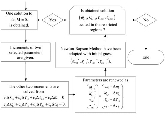
Figure 3.
Continuation algorithm.
If one of the roots of Equations (13) and (14) is obtained at step , denoted as , then the initial guess of the root of Equation (13) and (14) at step is assumed to be
where , , , and are small increments for each parameter. Substituting Equation (15) into Equations (13) and (14), expanding them in Taylor’s series in the vicinity of zero, and keeping only the linear parts yield the following:
where are represented in Equations (A1)–(A8) of the Appendix A. Then, it follows from Equation (16) that the other two increments can be solved numerically to obtain any small increments. This procedure is then repeated for a series of roots, which are located at the critical boundaries.
2.3. Analytical Prediction for Nonlinear Chatter with Period
As will be mentioned later, two regions (labeled Regions I and II) of Figure 4 were selected as typical cases with which to analyze the chatter motions due to the boundaries in Regions I and II being distinct. It can be seen that the time delays will lead to crossing different boundaries so that the chatter motions occur in different frequencies for a fixed value of contact stiffness, for example, , and two different values at and correspond to two different wheel speeds at rad/s and rad/s. To gain a deep understanding of the origin of nonlinear grinding chatter, the method of multiple scales (MMS) [34,35] can be employed to obtain an analytical description of the chatter responses. This demonstrates the relation between , , and the chatter motion of the grinding process, where is considered to be a variable parameter.
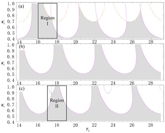
Figure 4.
Chatter boundaries for different fixed values of . (a) ; (b) ; (c) .
2.3.1. Analytical Preliminary
For Equation (8), if two time scales are introduced and given by , and , then one has
and
As mentioned above, is considered to be a variable parameter. Thus, perturbing in from the boundary yields
where corresponds the value at the boundary and is called the detuning parameter. The delayed terms in Equation (18) can be expanded as
Substituting Equations (18)–(20) into Equation (8), and collecting the coefficients of and , one has
and
For any values of the fixed parameters except for , the nontrivial solution to Equation (21) can be written as
where is the slow-time-domain variable for the chatter amplitude, stands for the complex conjugation of the preceding terms, and is the frequency of the critical chatter motion corresponding to . The eigen vector can be determined by solving the following equation:
Here, the undetermined eigenvector is determined by fixing the value of the first element as 1.
2.3.2. Analytical Expression
Substituting Equation (23) into Equation (22) yields
where stands for the terms that do not produce secular terms and the terms that do lead to secular terms, given by
with
To eliminate the terms noted as , we can seek a particular solution to Equation (25) in the following form [31]
so that
Based on the Fredholm alternative, there exists a solution of Equation (28) if and only if
where is determined by
Substituting Equation (26) into Equation (29) with Equation (30) yields the solvability condition, given by
where
To obtain the amplitude and frequency of the chatter motion, we can transform Equation (31) in terms of polar coordinates:
and substituting Equation (33) into Equation (31) and separating the real and imaginary parts yield
where and are the real and imaginary parts, respectively. It follows from Equation (34) that there are two steady-state solutions when and have different signs, where one of them is the trivial solution and another the periodic solution given by . It is well known that the trivial solution is stable, but the periodic one locally unstable, for negative and positive [32,33]. Similarly, the trivial solution loses its stability so that the period solution becomes stable for positive and negative . Physically, the regenerative force leads to chatter motion in the grinding process. Correspondingly, the solution of Equation (8) can be expressed as
where and are the nontrivial equilibrium solutions of Equation (34), , and (). Moreover, the periodic solution represented in Equation (35) is stable for and , where is the nonlinear chatter amplitude and the nonlinear chatter frequency. This implies that the grinding process undergoes a supercritical Hopf bifurcation so that the stable periodic chatter occurs in the system under consideration. It will be seen that the amplitudes of those periodic chatters are quantitatively distinct and the corresponding frequencies perform different modes when crosses those boundaries. This is shown using different colors in Figure 4.
3. Results
3.1. Chatter Boundaries
As stated in Table 1, some physical parameters of the grinding process formulated in Equation (1) can be fixed to obtain the critical boundaries. These parameters are derived from real engineering. Correspondingly, those dimensionless parameters can be computed by Equation (7), and are displayed in Table 2. The restricted ranges of the undetermined physical and corresponding dimensionless parameters with respect to the regenerative effect are stated in Table 3.

Table 1.
Fixed physical parameters of the grinding process.

Table 2.
Fixed dimensionless parameters of the grinding process.

Table 3.
The optional physical and corresponding nondimensional parameters of the grinding process.
To obtain the continuation algorithm for the roots of Equations (13) and (14), an initial guess of the values of , , , and is required for iteration. To this end, and are fixed, and and are solved from Equations (13) and (14). Defining
and using = 0, one can eliminate from Equations (13) and (14), resulting in an equation governed by , where is a unique unknown variable. As shown in Figure 5, can be solved from for and two distinct values of . It can be seen from Figure 5 that there exist multiple solutions of , which can be considered as the initial guesses to be substituted into Equations (13) and (14). Then, a series of true solutions can be obtained via the NRM. For example, if is taken into account in an initial guess, to be substituted into when , then one can obtain the true solutions of given by . Substituting into Equation (13), one can obtain a series of the valid solutions given by , , and , which are located in the valid region of . The other cases were computed in a similar way, and all of the results are represented in Table 4.
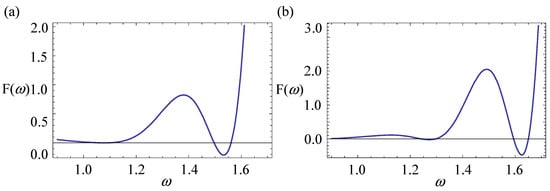
Figure 5.
for (a), , and (b) .

Table 4.
Starting points of the continuation algorithm.
Following the CA mentioned above, the critical boundaries displayed on some surfaces were obtained and are shown in Figure 6, where the blue surfaces are the critical boundaries starting from the initial guesses given by ω = 1.099. The orange ones represent those starting from ω = 1.605. It should be noted that the surfaces derived from ω = 1.572 and ω = 1.304 are connected smoothly, and both of the surfaces are plotted in a purple color. It follows from Figure 6 that a low value of does not induce chatter vibration for any values of or . This implies that the effects of regenerative force on the stability of the grinding system are not apparent when the contact stiffness is low. The flexibility of the grinding wheel and the workpiece, the contact width, and the processing temperature will affect the contact stiffness. The regenerative force will induce regenerative chatter, along with the contact stiffness increasing. To illustrate the effects of the significant contact stiffness and the relation between the critical and chatter boundaries, some cross sections by and are shown in Figure 4 and Figure 7, respectively. The critical curves correspond with Figure 6 in terms of color. Thus, the chatter boundary surrounding the grey region can be seen clearly. In Figure 7, the chatter-free region, in grey, is related to and when the value of the contact stiffness is greater than . It can be seen from Figure 7 that some rotation speed of both the wheel and the workpiece persists so that the system remains chatter-free. Such situations are referred to as “safe harbors” for the grinding process. All of the results mentioned above can also be seen in Figure 4.
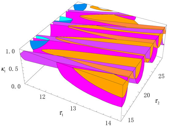
Figure 6.
Critical boundaries in the parameter space .
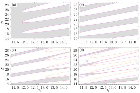
Figure 7.
Chatter boundaries surrounding the grey region for some fixed values of . (a) ; (b) ; (c) ; (d) .
It is should be noted that the critical boundary is different from the chatter one. The intersection surrounded by all critical boundaries shows the stable region of the trivial equilibrium. Its boundary is the chatter one. This implies that the grinding process is chatter-free when , , and are located within the region in grey. Various chatter motions may occur during the grinding process for , , and , being located within the white regions. To classify these chatter motions, two regions (labeled Regions I and II) in Figure 4 were selected for further nonlinear analysis, as represented in the following section.
3.2. Chatter Prediction
Letting and respectively, Regions I and II in Figure 4 are redisplayed in Figure 8, and the critical values of the relative parameters are represented in Table 5 and Table 6. We can observe chatter motions with varying along the directions labeled A, B, and C for , respectively.
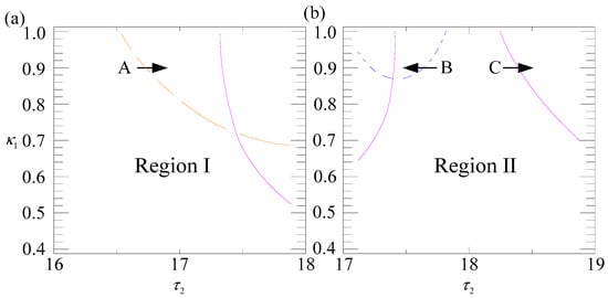
Figure 8.
Enlarged regions in Figure 4. (a) Region I; (b) Region II.

Table 5.
Critical values of and .

Table 6.
Corresponding eigenvectors.
When τ2 crosses the dot-dashed orange boundary along the direction of Label A, using Equations (34) and (35) yields the chatter motion derived from supercritical Hopf bifurcation [36,37,38].
Similarly, for cases crossing through the dashed blue and solid purple boundaries along Labels B and C, respectively, one can obtain two distinct periodic chatter motions, given by
and
It follows from Equations (37)–(39) that the chatter motions are different, both qualitatively and quantitatively. On one hand, there exist significant differences in amplitude among the three types of chatter motion. On the other hand, the corresponding modes are also different when is perturbed near different boundaries. Moreover, the almost-asynchronized chatter yields a significant fluctuation in the grinding depth for high chatter amplitude, because the workpiece and wheel always move opposite to each other. Thus, the largest vibration given in Equation (37) indicates the worst surface finish compared with the other two. Therefore, Region I in Figure 8 is a worse choice for grinding a part when compared with Region II. This implies that it is necessary to study the dynamic motions of the grinding process near different chatter boundaries such that one can further understand the relations between the chatter motions and the designed parameters.
An interesting phenomenon can also be seen: high chatter is related to high frequency. Physically, both high frequency and high amplitude indicate high chatter energy. Thus we conclude that a suitable choice of the designed parameter, i.e., the rotational workpiece speed for , may decrease the chatter energy or even eliminate the chatter. Similarly, changing the speed of the grinding wheel can also achieve the same goal.
To verify the validity of the present prediction, we compared the analytical results with those from the numerical simulation, as shown in Figure 9. Figure 9 shows the bifurcation diagrams (left column), the time histories (center column), and the corresponding phase diagrams (right column), with varying along the directions of the different labels for Labels A, B, and C, where the solid lines represent the results from Equations (37), (38), and (39) and the dots stand for the results from the numerical simulation of Equation (8). It can be seen from Figure 9 that the analytical prediction is in agreement with the result of the simulation. To observe the chatter motions of both the workpiece and the wheel, the relations between and are also plotted in Figure 9g–i, which show that the chatter motions of the workpiece and the wheel are in opposite directions with small phase differences. This suggests that the periodic motions of the two devices are almost asynchronized. In addition, it has not been found that the chatter motions of the grinding wheel and the workpiece occur in the same direction for any of the allowed parameters. We conclude that the mathematical equation under consideration herein may not model this phenomenon.
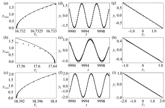
Figure 9.
Chatter motions: bifurcation diagrams (left column), time histories (center column), and the corresponding phase diagrams (right column), with varying along the directions of the different labels. The solid lines are the results from Equations (37)–(39), and the dots stand for those from the numerical computation for Equation (8). (a) Bifurcation diagrams along with Label A; (b) bifurcation diagrams along with Label B; (c) bifurcation diagrams along with Label C; (d) time history of with and ; (e) time history of with and ; (f) time history of with and ; (g) phase diagram of and with and ; (h) phase diagram of and with and ; (i) phase diagram of and with and .
4. Discussion
This paper proposes a full procedure for the analysis of nonlinear grinding chatter. Due to the doubly regenerative effects of both the wheel and workpiece surfaces, the dynamic model has two distinct time delays with transcendence eigen equations. Therefore, a continuation algorithm for both the path following iteration and the generation of initial guesses has been proposed. Compared with our previous works, in which we randomly generated seeds for the initial guess, this procedure does not miss any initial guesses for the boundaries. Moreover, this work used the method of multiple scales in vector form, which yielded a periodic responses for each variable. Thus the dynamic characteristics of chatter motion can be studied, for the first time unveiling the almost-asynchronous motion of workpiece and wheel displacements.
The rotating workpiece is regarded as a slender Euler–Bernoulli beam, and the grinding wheel at an angular speed as a rigid body with which to model a cylindrical plunge grinding process. This model is employed to predict the stability of the process and the nonlinear chatter motion.
Three chatter motions corresponding to three mode frequencies were analytically predicted for when the grinding process loses its stability. The prediction provided two interesting phenomena: that chatter vibration with high amplitude is always related to high frequency, and that the chatter motions are almost asynchronous, with a small difference in phase. This also suggests that it is necessary to predict the nonlinear chatter motions, since high chatter energy is more dangerous in the grinding process.
The synchronous and other nonlinear chatter motions of the workpiece and the grinding wheel have not been found for these parameters. This suggests that the present mathematical equation cannot model these phenomena. It is necessary to propose a new model, which will be discussed in our future research. Moreover, this study focused only on the grinding dynamics, which are one of various concerns in designing a grinding process. Other factors influencing the grinding process include the material removal rate, heat dissipation, etc., which should be systematically considered for high-efficiency grinding.
5. Conclusions
Regenerative force is not strong enough to induce chatter vibration during the grinding process as long as the contact stiffness between the workpiece and the wheel is small. When the contact stiffness exceeds a critical value, the stability of the grinding process becomes related to the rotation speeds of the workpiece and the wheel. Thus, we can conclude that the regenerative force has a qualitative effect on the grinding stability. Furthermore, based on the chatter boundaries obtained through CA, we suggest that a softer grinding wheel and suitable rotation speeds of the workpiece and the wheel should be chosen to avoid chatter vibrations. According to a nonlinear dynamic analysis, various periodic chatter born from supercritical Hopf bifurcation have been found. They all presented almost asynchronized vibration between the motion of the workpiece and that of the wheel.
Author Contributions
Conceptualization, T.S. and Y.Y.; methodology, T.S.; software, T.S.; formal analysis, T.S.; writing—original draft preparation, T.S.; writing—review and editing, Y.Y.; visualization, Y.Y.; supervision, Y.Y.; project administration, Y.Y.; funding acquisition, Y.Y. All authors have read and agreed to the published version of the manuscript.
Funding
This research was funded by National Natural Science Foundation of China (Grants No. 12072068, 11872147, 11932015, and 52175046), and Sichuan Science and Technology Program (Grant No. 2023YFG0050).
Data Availability Statement
No new data were created or analyzed in this study. Data sharing is not applicable to this article.
Conflicts of Interest
The authors declare no conflict of interest.
Appendix A
The coefficients in Equation (16) are given by
and
References
- Meng, Q.; Guo, B.; Zhao, Q.; Li, H.; Jackson, M.J.; Linke, B.S.; Luo, X. Modelling of grinding mechanics: A review. Chin. J. Aeronaut. 2022. [Google Scholar] [CrossRef]
- Brinksmeier, E.; Aurich, J.C.; Govekar, E.; Heinzel, C.; Hoffmeister, H.W.; Klocke, F.; Peters, J.; Rentsch, R.; Stephenson, D.J.; Uhlmann, E.; et al. Advances in modeling and simulation of grinding processes. CIRP Ann.-Manuf. Technol. 2006, 55, 667–696. [Google Scholar] [CrossRef]
- Altintas, Y.; Weck, M. Chatter stability of metal cutting and grinding. CIRP Ann.-Manuf. Technol. 2004, 53, 619–642. [Google Scholar] [CrossRef]
- Inasaki, I.; Karpuschewski, B.; Lee, H.S. Grinding chatter—Origin and suppression. CIRP Ann.-Manuf. Technol. 2001, 50, 515–534. [Google Scholar] [CrossRef]
- Sun, C.; Liu, Z.; Lan, D.; Duan, J.; Xiu, S. Study on the influence of the grinding chatter on the workpiece’s microstructure transformation. Int. J. Adv. Manuf. Technol. 2018, 96, 3861–3879. [Google Scholar] [CrossRef]
- Yan, Y.; Xu, J.; Wiercigroch, M. Stability and dynamics of parallel plunge grinding. Int. J. Adv. Manuf. Technol. 2018, 99, 881–895. [Google Scholar] [CrossRef]
- Wang, Z.; Li, C.; Xu, M.; Zhang, Y. Dynamic analysis and stability prediction of nonlinear feed system coupled with flexible workpiece. J. Sound Vib. 2022, 520, 116597. [Google Scholar] [CrossRef]
- Sun, Y.; Yan, S. Dynamics identification and stability analysis in turning of slender workpieces with flexible boundary constraints. Mech. Syst. Signal Process. 2022, 177, 109245. [Google Scholar] [CrossRef]
- Tu, G.; Dong, X.; Qian, C.; Chen, S.; Hu, L.; Peng, Z. Intra-wave modulations in milling processes. Int. J. Mach. Tools Manuf. 2021, 163, 103705. [Google Scholar] [CrossRef]
- Irino, N.; Imabeppu, Y.; Higuchi, Y.; Shinba, Y.; Kawai, K.; Suzuki, N.; Kaneko, J.; Kakinuma, Y.; Mori, M. Vibration analysis and cutting simulation of structural nonlinearity for machine tool. CIRP Ann.-Manuf. Technol. 2021, 70, 317–320. [Google Scholar] [CrossRef]
- Jiang, X.; Guo, M.; Li, B. Active control of high-frequency tool-workpiece vibration in micro-grinding. Int. J. Adv. Manuf. Technol. 2018, 94, 1429–1439. [Google Scholar] [CrossRef]
- Yuan, L.; Jarvenpa, V.-M.; Keskinen, E.; Cotsaftis, M. Simulation of roll grinding system dynamics with rotor equations and speed control. Commun. Nonlinear Sci. Numer. Simul. 2002, 7, 95–106. [Google Scholar] [CrossRef]
- Li, H.Q.; Shin, Y.C. A time-domain dynamic model for chatter prediction of cylindrical plunge grinding processes. ASME J. Manuf. Sci. Eng. 2006, 128, 404–415. [Google Scholar] [CrossRef]
- Thompson, R.A. On the doubly regenerative stability of a grinder: The effect of contact stiffness and wave filtering. ASME J. Eng. Ind. Ser. B 1992, 114, 53–60. [Google Scholar] [CrossRef]
- Liu, Z.H.; Payre, G. Stability analysis of doubly regenerative cylindrical grinding process. J. Sound Vib. 2007, 301, 950–962. [Google Scholar] [CrossRef]
- Xu, J.; Chung, K.W.; Chan, C.L. An efficient method for studying weak resonant double Hopf bifurcation in nonlinear systems with delayed feedbacks. SIAM J. Appl. Dyn. Syst. 2007, 6, 29–60. [Google Scholar] [CrossRef]
- Molnar, T.G.; Dombovari, Z.; Insperger, T.; Stepan, G. On the analysis of the double Hopf bifurcation in machining processes via centre manifold reduction. Proc. R. Soc. A Math. Phys. Eng. Sci. 2017, 473, 20170502. [Google Scholar] [CrossRef]
- Mokhtari, A.; Jalili, M.M.; Mazidi, A. Study on frequency response and bifurcation analyses under primary resonance conditions of micro-milling operations. Appl. Math. Model. 2020, 87, 404–429. [Google Scholar] [CrossRef]
- Chung, K.-W.; Liu, Z. Nonlinear analysis of chatter vibration in a cylindrical transverse grinding process with two time delays using a nonlinear time transformation method. Nonlinear Dyn. 2011, 66, 441–456. [Google Scholar] [CrossRef]
- Nayfeh, A.H.; Chin, C.M.; Pratt, J. Perturbation methods in nonlinear dynamics—Applications to machining dynamics. ASME J. Manuf. Sci. Eng. 1997, 119, 485–493. [Google Scholar] [CrossRef]
- Nayfeh, A.H.; Balachandran, B. Applied Nonlinear Dynamics: Analytical, Computational, and Experimental Methods; John Wiley & Sons, Inc.: New York, NY, USA, 1995. [Google Scholar]
- Engelborghs, K.; Luzyanina, T.; Roose, D. Numerical bifurcation analysis of delay differential equations using DDE-BIFTOOL. ASM Trans. Math. Softw. 2002, 28, 1–21. [Google Scholar] [CrossRef]
- Li, Z.; Yan, R.; Tang, X.; Peng, F.; Xin, S.; Wu, J. Analysis of the effect of tool posture on stability considering the nonlinear dynamic cutting force coefficient. J. Manuf. Sci. Eng. 2021, 143, 081009. [Google Scholar] [CrossRef]
- Rowe, W.B. Principles of Modern Grinding Technology; Elsevier, Inc.: New York, NY, USA, 2009. [Google Scholar]
- Yan, Y.; Xu, J.; Wiercigroch, M. Influence of workpiece imbalance on regenerative and frictional grinding chatters. Procedia IUTAM 2017, 22, 146–153. [Google Scholar] [CrossRef]
- Yan, Y.; Xu, J.; Wiercigroch, M. Regenerative chatter in a plunge grinding process with workpiece imbalance. Int. J. Adv. Manuf. Technol. 2017, 89, 2845–2862. [Google Scholar] [CrossRef]
- Liu, X.; Long, X.; Zheng, X.; Meng, G.; Balachandran, B. Spatial-temporal dynamics of a drill string with complex time-delay effects: Bit bounce and stick-slip. Int. J. Mech. Sci. 2020, 170, 105338. [Google Scholar] [CrossRef]
- Qian, J.; Sun, X.; Xu, J. A data-driven reconstruction method for dynamic systems with multistable property. Nonlinear Dyn. 2023, 111, 4517–5441. [Google Scholar] [CrossRef]
- Qi, Z.; Sun, X. The modular gait design of a soft, earthworm-like locomotion robot driven by ultra-low frequency excitation. Appl. Sci. 2023, 13, 2723. [Google Scholar] [CrossRef]
- Sun, X.; Qi, Z.; Xu, J. A novel multi-layer isolation structure for transverse stabilization inspired by neck structure. Acta Mech. Sin. 2022, 38, 521543. [Google Scholar] [CrossRef]
- Du, J.; Liu, X.; Long, X. Time delay feedback control for milling chatter suppression by reducing the regenerative effect. J. Mater. Process. Technol. 2022, 309, 11774. [Google Scholar] [CrossRef]
- Nayfeh, A.H.; Pai, P.F. Linear and Nonlinear Structural Mechanics; John Wiley & Sons, Inc.: New York, NY, USA, 2004. [Google Scholar]
- Nayfeh, A.H. Order reduction of retarded nonlinear systems—The method of multiple scales versus center-manifold reduction. Nonlinear Dyn. 2008, 51, 483–500. [Google Scholar] [CrossRef]
- Yan, Y.; Liu, G.; Wiercigroch, M.; Xu, J. Safety estimation for a new model of regenerative and frictional cutting dynamics. Int. J. Mech. Sci. 2021, 201, 106468. [Google Scholar] [CrossRef]
- Yan, Y.; Xu, J.; Wiercigroch, M.; Guo, Q. Statistical basin of attraction in time-delayed cutting dynamics: Modelling and computation. Phys. D: Nonlinear Phenom. 2021, 416, 132779. [Google Scholar] [CrossRef]
- Sahu, G.N.; Jain, P.; Wahi, P.; Law, M. Emulating bistabilities in turning to devise gain tuning strategies to actively damp them using a hardware-in-the-loop simulator. CIRP J. Manuf. Sci. Technol. 2021, 32, 120–131. [Google Scholar] [CrossRef]
- Sahu, G.N.; Law, M.; Wahi, P. Adaptive control to actively damp bistabilities in highly interrupted turning processes using a hardware-in-the-loop simulator. J. Vib. Control 2021, 29, 1141–1151. [Google Scholar] [CrossRef]
- Sahu, G.N.; Deora, P.; Law, M.; Wahi, P. Adaptive model-free gain tuning for active damping of machine tool vibrations. J. Vib. Eng. Technol. 2022, 10, 2799–2808. [Google Scholar] [CrossRef]
Disclaimer/Publisher’s Note: The statements, opinions and data contained in all publications are solely those of the individual author(s) and contributor(s) and not of MDPI and/or the editor(s). MDPI and/or the editor(s) disclaim responsibility for any injury to people or property resulting from any ideas, methods, instructions or products referred to in the content. |
© 2023 by the authors. Licensee MDPI, Basel, Switzerland. This article is an open access article distributed under the terms and conditions of the Creative Commons Attribution (CC BY) license (https://creativecommons.org/licenses/by/4.0/).