Review

Efficient Utilization of Carbon Dioxide in Power-to-Gas and Power-to-Liquid Processes: A Vital Path to Carbon Neutrality

1
State Key Laboratory of Materials-Oriented Chemical Engineering, College of Chemical Engineering, Nanjing Tech University, Nanjing 211816, China
2
School of Energy Science and Engineering, Nanjing Tech University, Nanjing 211816, China
*
Authors to whom correspondence should be addressed.
Processes 2023, 11(7), 1898; https://doi.org/10.3390/pr11071898
Submission received: 24 May 2023 / Revised: 20 June 2023 / Accepted: 21 June 2023 / Published: 24 June 2023

Abstract

:
A large number of CO2 emissions caused a serious greenhouse effect, aggravating global warming and climate change. Therefore, CO2 utilization has been a research hotspot, especially after the Paris Agreement, and among the various CO2 utilization technologies, the power-to-gas (PTG) and power-to-liquid (PTL) processes have recently attracted significant attention because they can transform CO2 into fuels and/or chemicals. Considering the lack of detailed information in the literature with regard to process design and economic analysis, we have critically and comprehensively summarized the recent research progresses concerning the PTG and PTL processes. Herein, we mainly focus on the power-to-methane in the case of PTG and the power-to-syncrude, power-to-methanol, and power-to-ethers in the case of PTL. From the technical point of view, the bottleneck problem of PTG and PTL processes is the low system efficiency, which can be improved by heat integration and/or process integration. Meanwhile, from the economic point of view, the production cost of PTG and PTL processes needs to be further reduced by the following measures, such as by increasing the carbon tax, lowering the electricity price, improving the electrolysis efficiency, reducing the capital expenditure of the electrolytic cell, and formulating sustainable incentive policies. The main purpose of the paper is to present a comprehensive updated review of CO2 utilization in PTG and PTL processes from process system integration, the techno-economic aspects, such as, state-of-the-art synthesis technologies, process system integration and the production cost, and provide useful information and reliable suggestions for the future development trends of the PTG and PTL processes.

Graphical Abstract

1. Introduction

According to the research report of the IEA, global CO2 emissions have exceeded 36.8 billion tons [1]. This is mainly attributed to fossil fuel burning [2], among which the energy-intensive sectors, dominated by electricity and heat, cover 45%, while the industrial sectors, including metal production and manufacturing, account for 23%, with the remaining portion mainly consisting of the transportation sector [3]. It is now widely recognized that the rising levels of CO2 leads to global warming and severe environmental problems such as a rise in sea levels, the melting of the polar regions, and ocean acidification [4]. More specifically, according to the prediction of the fifth assessment report of the Intergovernmental Panel on Climate Change (IPCC), if the emission of a greenhouse gas such as CO2 continues to increase, the global sea level will rise by 0.52–0.98 m until 2100 [5]. Simultaneously, extreme weather will increase significantly, which would pose a great threat to human survival. Therefore, it is necessary to reduce CO2 emissions and to limit the global temperature increase to 1.5–2 °C by the end of the 21st century [6].
Generally, there are four main ways to reduce CO2 emissions:
  • Improving the utilization rate of fossil energy. This way means using less energy to meet the energy service demand and directly reduce the use of fossil energy. However, burning fossil fuels inevitably produces CO2.
  • Using renewable energy with near-zero CO2 emissions, such as wind energy and solar energy. However, the widespread deployment of renewable energy is challenging due to its intermittent in time and space and low capacity factors [7].
  • Carbon capture and storage (CCS). In the case of CCS, CO2 is captured from the industrial flue gas and atmosphere, and then the CO2 is permanently stored in underground space, such as deep geological caves, salt aquifers, abandoned oil and gas fields, coal mines, and the seafloor [8]. CCS has been proven to be feasible from the technical aspect, but economic competitiveness, social acceptance, and environmental impacts are barriers to the development of CCS [9].
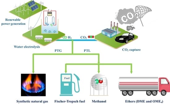
  • Carbon capture and utilization (CCU). In the case of CCU, CO2 is converted into various high value-added end products, such as methanol, dimethyl ether, synthetic natural gas (SNG), and liquid fuels [10]. Recently, various processes based on CCU are developed, which mainly include reforming, hydrogenation, carboxylation, mineralization, electrochemical, photochemical, plasma catalysis, and polymeric processes [11,12].
Among the various CO2 reduction ways, the CCU has gained widespread attention, especially power-to-gas (PTG) and power-to-liquid (PTL) processes based on CO2 catalytic conversion, which are further introduced from technical and economic aspects in the following sections. PTG and PTL processes realize the efficient utilization of CO2 and convert unstable renewable energy into stable chemical energy for storage [13,14]. In general, the PTG and PTL processes contain three sections: H2 production via water electrolysis using surplus renewable energy, CO2 capture from flue gas, and CO2 hydrogenation. This review mainly focuses on the CO2 hydrogenation technologies in the PTG and PTL. Hence, the water electrolysis and CO2 capture technologies are excluded from this review.
The products of PTG and PTL mainly depend on different CO2 hydrogenation processes. For the PTG process, the product SNG is injected into the existing natural gas pipe network or is transported by CNG tankers (Figure 1) [15]. For the PTL process, the product liquid hydrocarbons (C5+) are suitable to produce transportation fuels with a higher volumetric energy density, such as jet fuel, diesel, and gasoline. In addition, the product of PTL, such as methanol, olefin, and dimethyl ether, are used as the essential platform chemical (Figure 2) [16,17].
At present, low system efficiency and high production cost are the primary barriers to the large-scale deployment of PTG and PTL processes. Therefore, in this review, the recent research progresses of CO2 utilization in PTG and PTL processes are summarized, particularly in the aspects of synthesis technologies, technical performance improvement, and process system integration. In addition, the production cost of different products from PTG and PTL processes is illustrated and analyzed. Hence, the current study provides an extensive overview of PTG and PTL technologies in terms of system integration, process performance improvement, and production cost analysis. It aims to provide primary boundary conditions for future concepts with regard to performances and process designs, ultimately guiding subsequent advancements and facilitating benchmarking efforts.

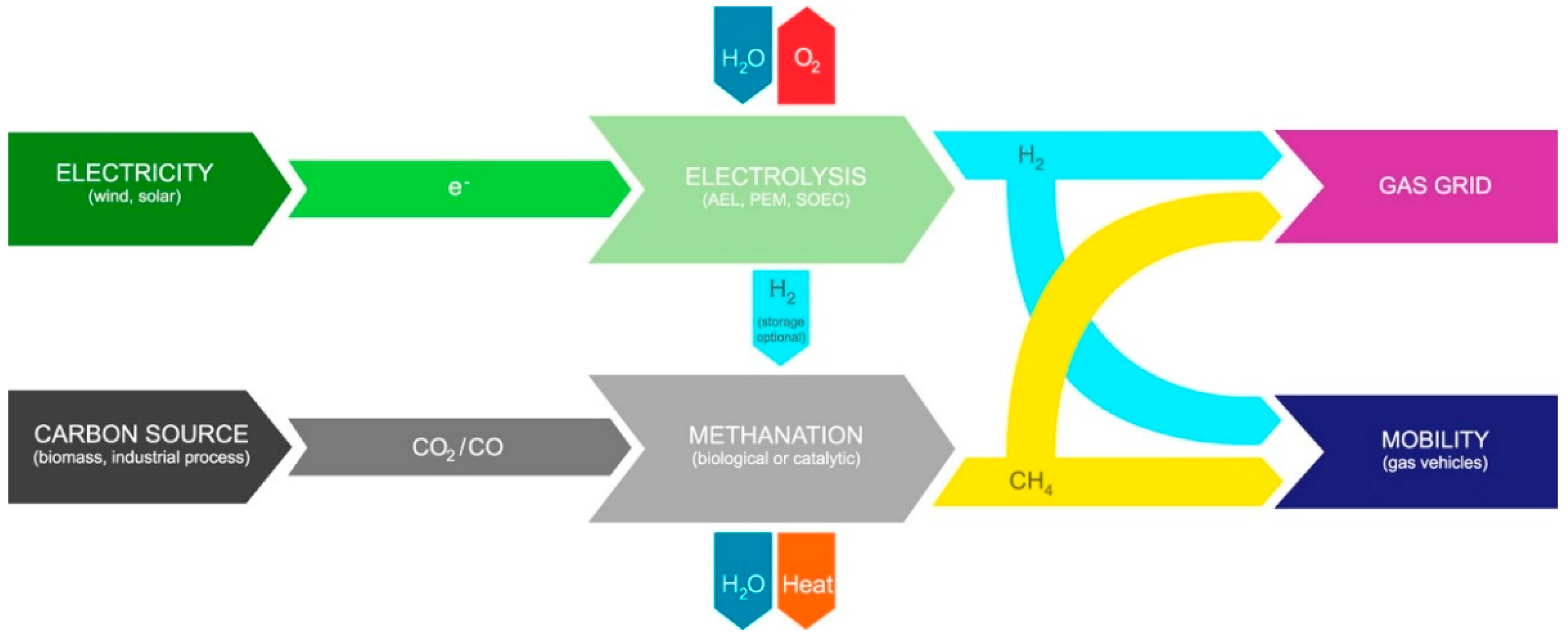
2. CO2 Utilization in Power-to-Gas Process

The PTG process primarily converts water and CO2 into SNG, in which the CO2 methanation (see Equation (1)) is an essential step [18]. The operating conditions, reactor configuration, product purification, process integration of CO2 methanation and H2O/CO2 co-electrolysis, and production cost analysis are presented in the following sections.
CO 2 ( g ) + 4 H 2 ( g ) cat . CH 4 ( g ) + 2 H 2 O ( g )   Δ r H m θ = 165   kJ / mol  

2.1. Effect of Operating Conditions on CO2 Methanation

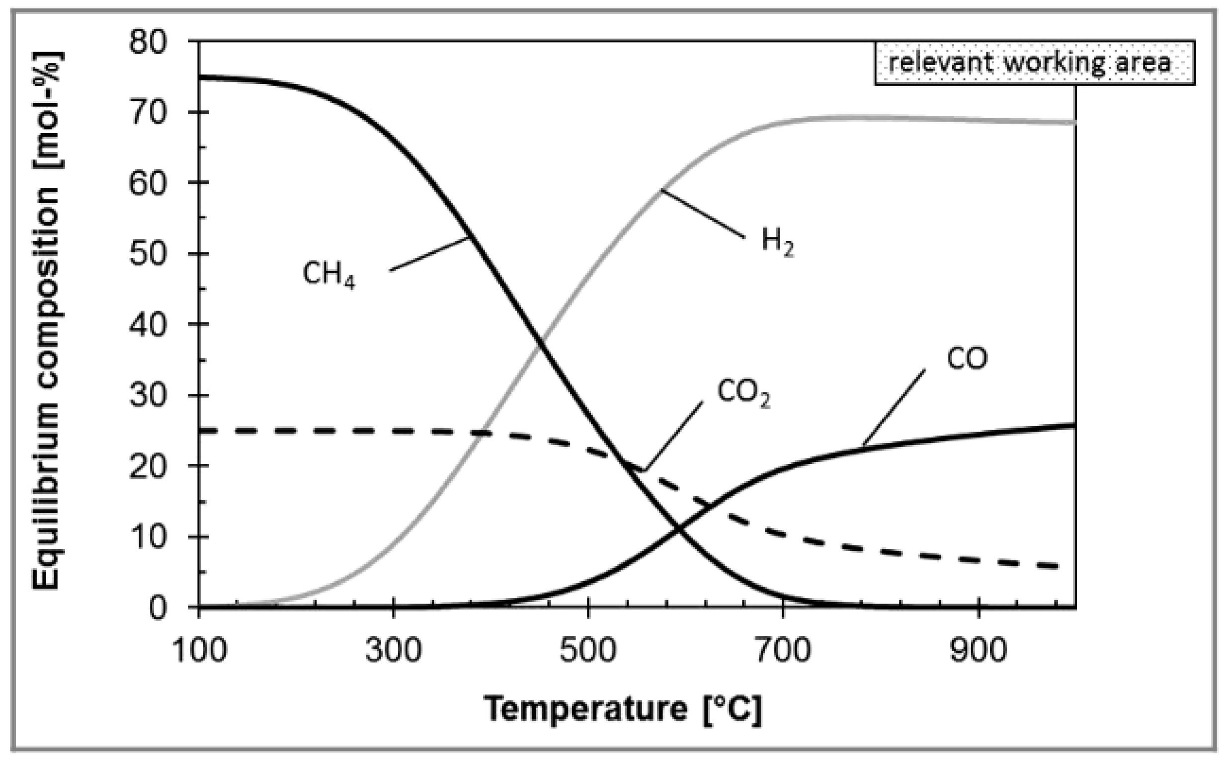
2.1.1. Effect of Operating Temperature

Considering that CO2 methanation is strongly exothermic, low temperature is therefore beneficial for CO2 methanation from a thermodynamic perspective. For example, Gao et al. found that CO2 conversion can reach 100% at about 200 °C [19]. However, from the aspect of reaction kinetics, high temperature tends to accelerate the reaction rate. However, when the temperature surpasses 450 °C, it is easy to cause an increase in CO by-product and a decrease in CO2 conversion due to dominating reverse water–gas shift (RWGS) side reaction [20]. Therefore, the typical operating temperature is generally at 450 °C [21].

2.1.2. Effect of Operating Pressure

In the typical temperature range of 200–600 °C, the CO2 conversion and CH4 selectivity increase as the operating pressure increases, which is attributed to a volume reduction in CO2 methanation. However, when the operating pressure exceeds 30 bar, the influence of pressure on the CO2 conversion is non-significant, while the operating cost is further increased. Therefore, an operating pressure of 10–30 bar is generally considered the most suitable from the technical and economic aspects [22].

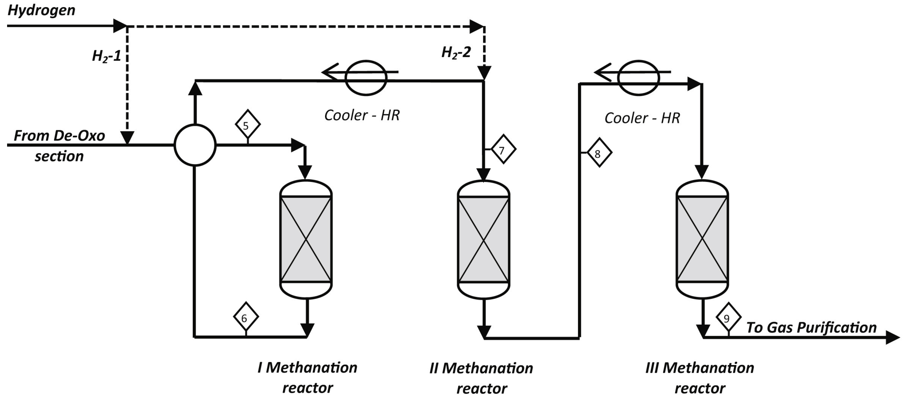
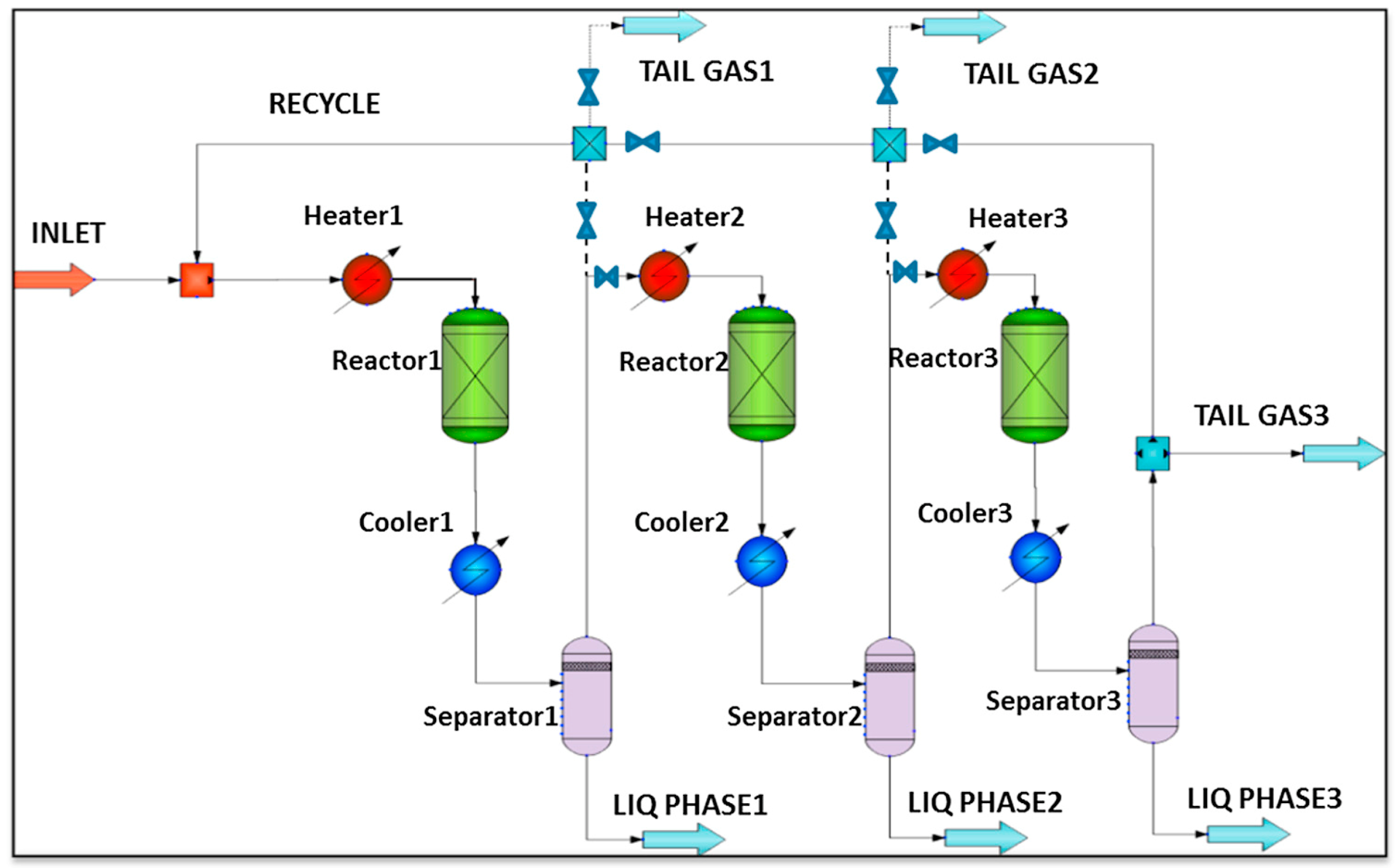
2.2. Effect of Reactor Configuration on CO2 Methanation

As highlighted above, an excessive operating temperature tends to cause a decrease in CO2 conversion and catalyst deactivation. Therefore, reactor temperature control has been the primary process constraint to realize full implementation in industry [23]. Some researchers have developed different reactors, which can be roughly divided into fixed-bed reactors, fluidized-bed reactors, three-phase reactors, and structured reactors.

2.2.1. Fixed-Bed Reactors

The fixed-bed reactors comprise multiple adiabatic reactors in series and interstage condensers to control the temperature rise. The number of reactors generally varies from one to four. At present, most of the commercial methanation processes have employed multiple fixed-bed reactors in series with interstage condensers, such as the Lurgi/BASF high temperature (HT) methanation process and Haldor Topsoe’s TREMP™ process (See Figure 3) [24,25]. Taking the three fixed-bed reactors in series with interstage condensers as an example, Iaquaniello found that CO2 conversion rose to more than 90% in the temperature range of 400–500 °C [26]. In addition, multiple reactors in series allow high catalyst load and space velocity, and the steam generated in the condensers can be used as utilities. However, the primary disadvantages of such reactors are high thermal resistance and hotspots, which can cause catalyst sintering.

2.2.2. Fluidized-Bed Reactors

The fluidized-bed reactors were developed by the US Bureau of Mines, and a pre-commercial fluidized-bed reactor was built and commercialized in 1982 [27]. In the fluidized-bed reactors, the catalyst particles are fluidized in the gaseous reactant, and the contact between the reaction gas and the catalyst particles is uniform. Therefore, the fluidized-bed reactors can achieve high mass and heat transfer and almost isothermal operating conditions. In addition, another significant advantage of the reactors is to remove, supplement, and recycle the catalyst continuously and easily during operation [28]. However, the attrition and the entrainment of the catalyst particles and the fluidization velocity limitation are major barriers to a large-scale application [29].

2.2.3. Three-Phase Reactors

The three-phase reactors were developed by Chem Systems Inc. in the 1970s, and the operating pressure of such reactors is up to 70 bar [24]. In the three-phase reactors, the solid catalyst particles are suspended in an inert liquid, such as dibenzyl toluene, and the reaction gas is in countercurrent contact with the catalyst. Similar to the fluidized-bed reactors, the three-phase reactors can achieve precise temperature control. The three-phase reactors are suitable for the dynamic operations of methanation [30,31]. When the feedstock fluctuates, the three-phase reactors are less prone to quick temperature changes. It is due to the fact that the inert liquid has a relatively large heat capacity. However, the evaporation and decomposition of the inert liquid are significant issues for three-phase reactors [32]. Table 1 presents the comparison of the reactor performance in the methanation process.

2.2.4. Structured Reactors

Structured reactors mainly include micro-channel reactors, membrane reactors, and enhanced-adsorption reactors [24].
(1) Micro-channel reactors
Micro-channel reactors contain multiple rectangular metal channels. The inner surface of the metal channel is covered by a thin layer of catalyst, while the outer surface is in contact with the cooling medium [33]. In fact, the metal channel can be regarded as the special catalyst carrier. Different from common catalyst carriers (alumina, zeolites, etc.), the carrier based on metal has excellent heat transfer properties and better temperature control ability [34]. In addition, the high surface-to-volume ratio significantly decreases the reactor volume [35]. Micro-channel reactors have been at a demonstration scale [36]. However, it should be pointed out that the micro-channel reactors are single-use systems. That is, if the catalyst is deactivated irreversibly, the whole reactor has to be replaced [37].
(2) Membrane reactors
Membrane reactors achieve the in situ reaction and separation in the same reactor simultaneously. Meanwhile, the membrane reactor could further facilitate the forward reaction and break the limitation of thermodynamic equilibrium by selectively removing the targeted products [38]. According to the selectivity and permeability of the membrane, the membrane reactor removes products in situ and breaks the thermodynamic limitation to further improve the CO2 conversion. For example, compared with the traditional fixed-bed reactors, the membrane reactors remove the steam via hydroxy sodalite (H-SOD) membrane in situ and increase the CO2 conversion by 26% [39]. However, high cost and the regular replacement of the membrane are the major disadvantages for membrane reactors.
(3) Enhanced-adsorption reactors
The enhanced-adsorption reactors control the reaction conditions to change the concentration of reactants and products and increase the conversion and yield [40]. The reactors can be divided into two types according to different adsorbents.
One kind of reactor is similar to the membrane reactors, and uses adsorbents to remove steam in situ and increase methane yield. The adsorbents generally choose zeolites that can be regenerated by pressure swing adsorption (PSA) technology. For example, Walspurger et al. used a Ni-based catalyst and zeolite 4A adsorbent, and found that the CO2 conversion reached close to 100% when operating pressure is atmospheric pressure, and the operating temperature is 250–350 °C [41]. Florian et al. investigated the thermodynamic performances of enhanced-adsorption CO2 methanation in a fixed bed reactor. As a result, it was found that the application of the enhanced-adsorption technology is beneficial for the highly exothermic CO2 methanation reaction [42].
Another kind of reactor employed bifunctional materials to integrate the CO2 capture and CO2 methanation. Bifunctional materials refer to nano-scale CO2 adsorbents uniformly dispersed on the surface of the catalysts. In the bifunctional materials, the adsorbents, such as CaO and hydrotalcite, directly capture CO2 from flue gas, and then the heat generated by CO2 methanation can promote CO2 desorption [43]. It should be noted that the process conducts the CO2 capture and CO2 methanation in the same reactor. Hence, the equipment investment is significantly decreased. In addition, under the action of the bifunctional materials, the CO2 conversion can reach 99% at 300 °C [44].

2.3. Product Purification

The crude product obtained by CO2 methanation generally contains H2O, unreacted H2 and CO2, which cannot be directly injected into the current natural gas pipelines. Therefore, purification of the crude product is necessary [45]. CO2 can be captured by amine absorption technologies, which is a well-known and implemented industrial method. For example, Becker et al. captured 90% of CO2 in the crude SNG via MDEA, captured 90% of H2 in the crude SNG via polysulfone membrane, and then recycled CO2 and H2 to the methanation reactor to improve total CO2 conversion and CH4 yield [46]. However, other CO2 capture technologies such as absorption, distillation, and flash separation have been widely used [47]. In addition to the aforementioned technologies, some emerging technologies, including membrane separation and PSA, also show enormous application potentials [48].
The presence of water in crude SNG causes severe damages. For example, water and methane form hydrate blockage on the valves and pipeline [49]. In addition, the surplus water decreases the transmission capacity of the pipeline and consumes additional electrical energy [50]. Hence, it is necessary to remove the water. The widely used technology in industry is absorption with triethylene glycol (TEG). The specific steps include the absorption of water with TEG in absorber, and the desorption of water from the water-loaded solvent in stripper [51]. However, its regeneration energy consumption is relatively high, and the system operation is complex [52]. In addition to the absorption method, the water in crude SNG can be cooled down and removed in the gas–liquid separator, which can combine with the membrane separation method to remove water in crude SNG to the ppmv level. For example, Chauvy et al. first used a gas–liquid separator to remove 99.99 vol% of water in the raw product, then used a membrane (the commercial Pebax®-based membrane) separator to reduce the H2O content to the ppmv level [53].

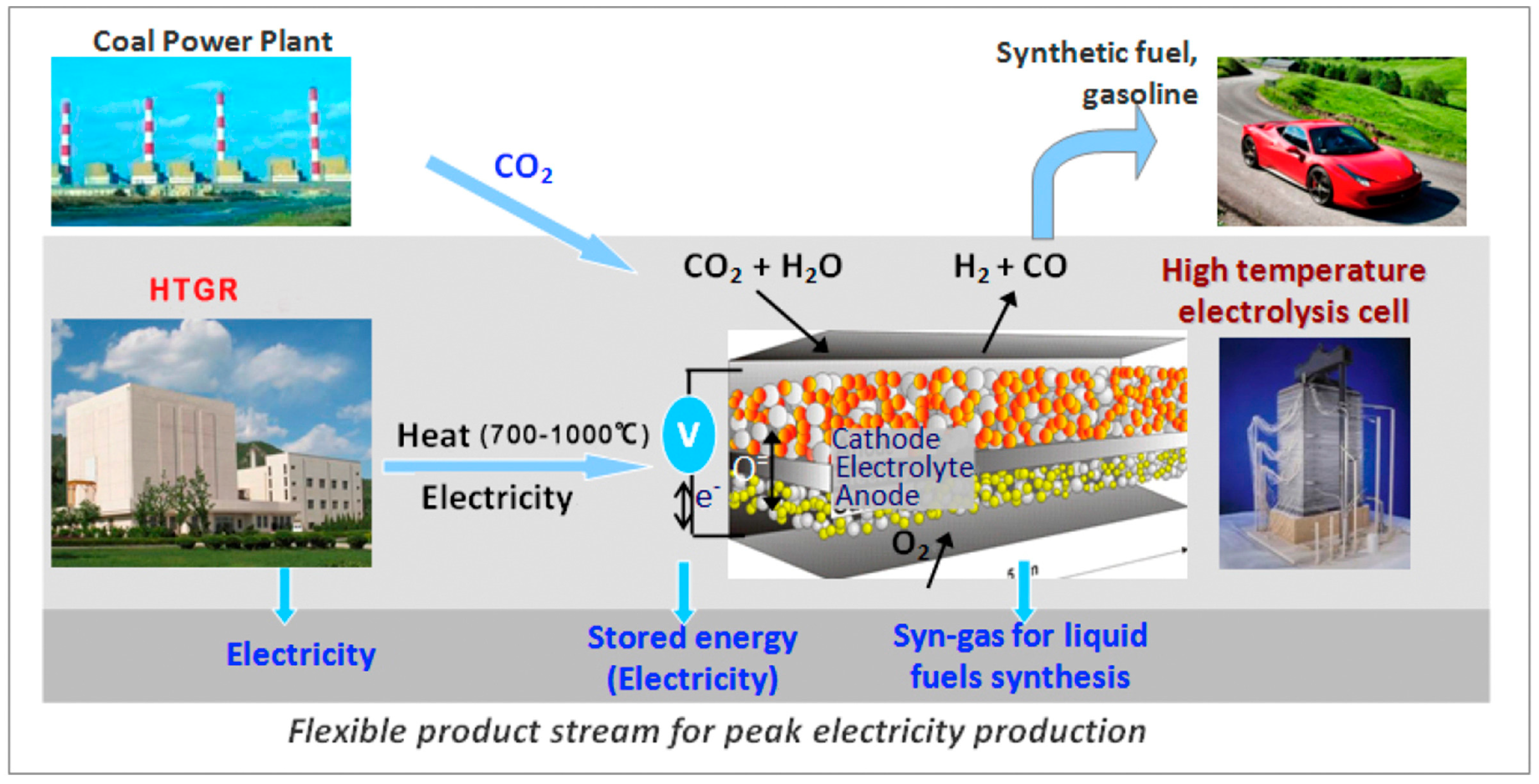
2.4. Process Integration of CO2 Methanation and H2O/CO2 Co-Electrolysis

For the PTG process, in addition to methanation reactors, electrolytic cells are another extremely important equipment. The electrolytic cell can efficiently convert steam/water into H2 and O2 using surplus renewable energy. According to the principle of water electrolysis, the electrolytic cell can be divided into three types: proton exchange membrane electrolytic cells (PEMECs), alkaline electrolytic cells (AECs), and solid oxide electrolytic cells (SOECs) [54]. Compared with other water electrolytic cells, the significant advantages of SOECs lie in their high-temperature operating nature and high electrolysis efficiency. The SOECs are currently in the pre-commercialization stage [55,56]. Considering the merits of SOECs, the integration process of CO2 methanation and H2O/CO2 co-electrolysis based on SOECs has been an interesting research area for fuel production in recent years.
From the perspective of energy utilization, the process integration achieves the comprehensive utilization of heat and reduces the dependence of the coupled system on external energy. For instance, Er-rbib et al. designed an integrated process of CO2 methanation and H2O/CO2 co-electrolysis and conducted the process modeling. Moreover, they conducted heat integration to maximize the utilization of reaction heat, which was divided into three parts. The first part was used to heat the stream at the inlet of the SOEC unit, the second part was used to generate electricity through the Rankine cycle, and the last part was used to capture CO2 and regenerate the solvent. The results presented that the overall power-to-gas energy efficiency reached 67.1% [57]. It is worth noting that H2O/CO2 co-electrolysis and CO2 methanation belong to two independent sections in the integrated process. However, Luo et al. found that coupling H2O/CO2 co-electrolysis and methanation into a tubular SOEC reactor has a higher system efficiency. They developed a two-dimensional multiscale electro-thermos tubular SOEC model based on their previous work [58] and realized the direct conversion of CO2 to CH4 in a single tubular reactor. Simultaneously, it was found that CO2 conversion was up to 98.7%, the CH4 yield was over 50%, and the electricity–gas conversion reached 94.5% [59]. The process breaks the boundary between H2O/CO2 co-electrolysis and methanation sections, which are carried out in a single reactor and reduce operational complexity and equipment cost.

2.5. Production Cost Analysis

The CO2 methane process is relatively mature in technology and has large-scale pilot plants. For example, the largest commercial CO2 methanation plant worldwide has been built and implemented in Germany [60]. However, economic competitiveness needs to be further improved. Guilera et al. evaluated the economic feasibility of SNG based on the electricity markets of different countries. They found that the production cost currently ranges from 70 to 125 EUR/MWh, which is 2–7 times higher compared with the price of traditional natural gas [61]. To further reduce the production cost of SNG, Blanco et al. proposed specific measures from the economic aspect. Low electricity prices (<10 EUR/MWh), low CAPEX (<1500 EUR), and numerous operating hours (>3000 h) are necessary [62]. Moreover, the operating form of the methanation reactor also significantly impacts the production cost. For example, Aicher et al. investigated the influence of methanation dynamics on production cost and found that, compared with a steady-state operation, the investment of the PTG process can be reduced by 8% in the case of operating the methanation dynamically [63]. In addition to the aforementioned factors, PTG process relies on the sufficient supply of hydrogen. Therefore, the cost of the hydrogen storage vessel is also important [64]. Gorre et al. proposed that the optimal of the hydrogen storage size and the methanation capacity can further reduce the production cost by up to 17% [65]. Overall, SNG is currently not competitive with conventional natural gas. However, Fambri et al. estimated that the levelized cost of SNG could decrease by 36% on average in 2030 due to the reduction in the cost of electrolyzer, hydrogen buffer, and methanation reactor [66]. In the long term, with the improvement of electrolysis efficiency, the expansion of production scale, and the flexible operational strategy of the power grid, the production cost of SNG may drop to 40 EUR/MWh, which is close to the cost of conventional natural gas [61,67].

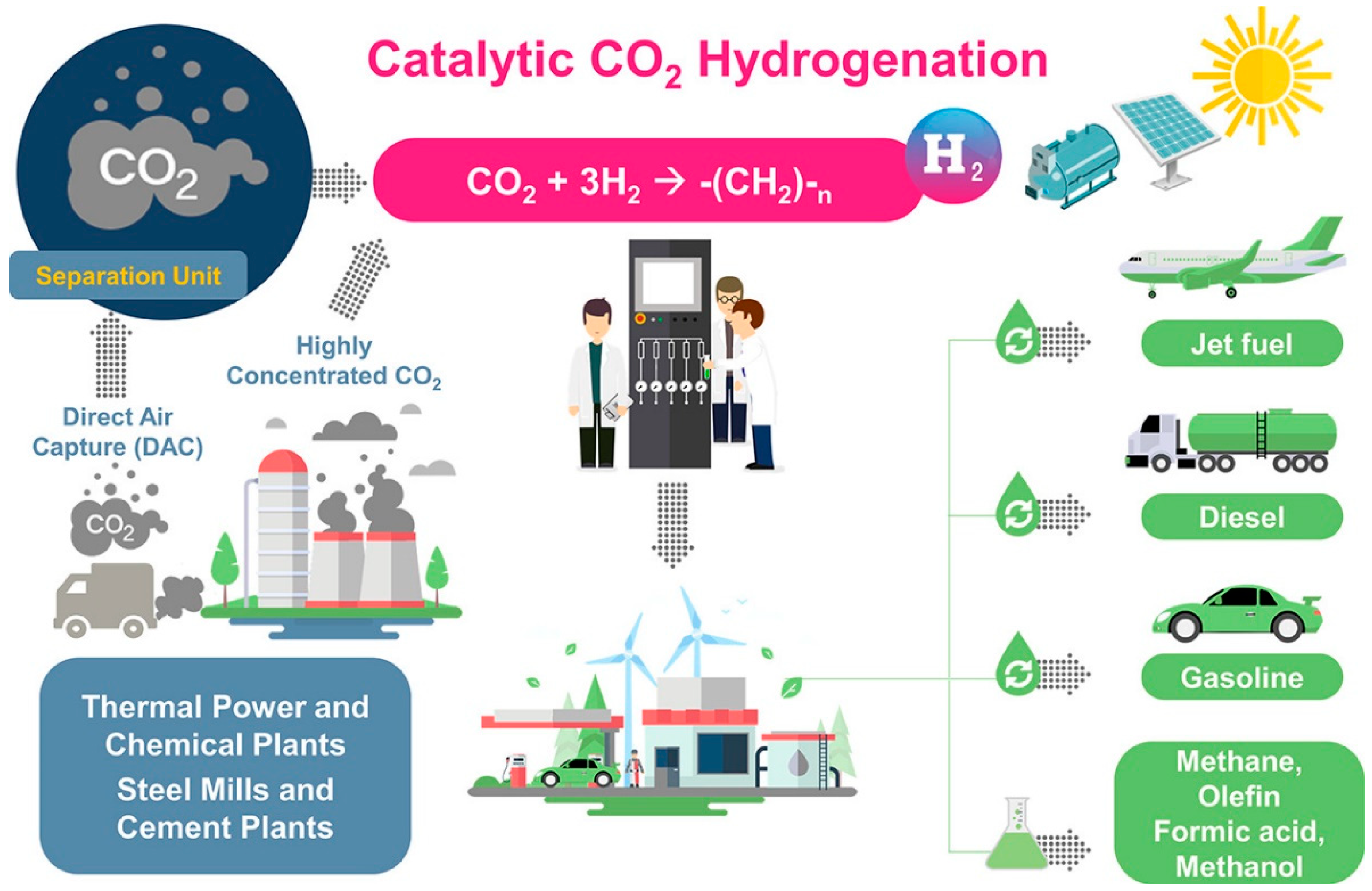
3. CO2 Utilization in PTL Processes

3.1. Power-to-Syncrude Process

Power-to-syncrude process mainly aims to convert water and CO2 into syncrude, in which, CO2 hydrogenation is a key step. The FTS route is the most effective way to produce C2+ products. Compared to petroleum-based products, the obtained products via the FTS route are free of sulfur, nitrogen, aromatics, and other toxic substances, and they can be used directly in subsequent refining processes or commercial consumption [68]. Herein, the product is mainly hydrocarbons with different carbon-chain lengths, such as gaseous hydrocarbons (C1–C4) and liquid fuels (C5–C20), and the product can be upgraded into gasoline, diesel, and jet fuel by subsequent upgrading steps [69]. The power-to-syncrude process can be classified into an indirect one composed of RWGS and Fe/Co-based Fischer–Tropsch synthesis (FTS), and the direct one combined with Fe-based FTS.

3.1.1. Indirect Power-to-Syncrude Process

In the indirect process, the first step is the syngas production via RWGS or H2O/CO2 co-electrolysis, and then the syngas is hydrogenated to generate syncrude via FTS. The crucial components are mainly the syngas production unit and the FTS unit, both of which will be the focus in the following sections.
(1) Syngas production via RWGS
The RWGS aims to convert CO2 and H2 into syngas (see Equation (2)), and further increase the transforming efficiency of CO2 [70]. Considering that the RWGS reaction is endothermic, high temperature is beneficial to the RWGS reaction from the perspective of thermodynamic equilibrium and reaction kinetics. However, the temperature is limited by the thermodynamic equilibrium. For example, in the case of Ni-based commercial catalyst and 800 °C, Kaiser et al. found that the CO2 conversion was almost 80%, and further increasing the temperature had a slight effect on CO2 conversion (Figure 4) [71]. However, the CO2 conversion can be further improved by the following ways, such as multiple reactors with interstage condensation devices in series and membrane separation. For example, Meiri et al. employed three RWGS reactors in series and periodically removed water, as shown in Figure 5. The results showed that the CO2 conversion reached 85% at 320 °C [72]. In addition, some researchers proposed a process integration of RWGS and membrane separation, which removes product steam in situ according to the selective permeability of the membrane. For example, Dzuryk et al. found the CO2 conversion reached 80–95% in water-permeable packed-bed membrane reactors when the operating temperature is 250 °C [73]. However, Membrane degradation is an unavoidable problem for the membrane separation process. Especially when the operating temperature is above 400°C, the amorphous membrane and polymer membrane are easy to rupture [74].
(2) Syngas production via H2O/CO2 co-electrolysis
H2O and CO2 co-electrolysis process integrates water electrolysis technology and the RWGS process to achieve a comprehensive energy utilization and to reduce the number of reactors and heat exchangers [75,76]. Compared with the traditional CO2 dry electrolysis, the co-electrolysis process dramatically improves the conversion of CO2 to CO due to the promoting effect of H2 [77] and overcomes the soot deposition suffered in the CO2 dry electrolysis. The schematic diagram is presented in Figure 6. However, the degradation of the cell remains a challenge for commercialization, making a better understanding of the reaction and degradation mechanism as well as further material developments necessary [78].
Considering that H2O and CO2 co-electrolysis is endothermic (see Equation (6)), high operating temperatures are beneficial to increase syngas production. In addition, Wang et al. found that high temperatures can enhance electrochemical reactions and reduce electrical energy consumption, making co-electrolysis have better cost benefits and a higher energy efficiency [79]. Like the RWGS process, the co-electrolysis process inevitably has side reactions, such as CO methanation. Samavati et al. found that when the operating temperature and pressure are 900 °C and 25 bar, the methane content in the product is up to 5 mol%. Increasing the electrolysis temperature can further decrease the methane content. However, the excessive operating temperatures are impractical due to the temperature limit that the electrode material can tolerate [80]. Recently, the co-electrolysis process has been feasible from the technical aspect [81]. Sunfire GmbH reported that a commercial high-temperature H2O/CO2 co-electrolysis system had run successfully in Dresden, Germany [82]. However, compared with the relatively mature RWGS process, the co-electrolysis process is still far from large-scale industrial applications.
Figure 6. The schematic diagram of co-electrolysis of H2O and CO2. Reprinted with permission from Zhang et al. [83]. Copyright (2017) Elsevier.
Processes 11 01898 g006
(3) Syngas conversion via Fe/Co-based FTS
  • Fe-based FTS
Fe-based catalysts show excellent potential in converting syngas into light olefins (C2–C4), in which olefins are mainly α-olefins (see Equation (3)) [84]. The operating temperature is adjusted at a wide range, at 200–350 °C [85]. In addition, Fe-based catalysts have significant water–gas shift (WGS) activity (see Equation (5)), which are widely used for the FTS of syngas with insufficient H2 [86]. Recently, extensive efforts have been made in Fe-based FTS. For example, Landau et al. developed a system of three packed-bed FTS reactors with interstage cooling in series, which can remove the water and liquid hydrocarbons in the product. It was found that the CO2 conversion increased from 60% to 89% compared with a single packed-bed FTS reactor [87]. Based on the work by Landau et al., Meiri et al. conducted a comparison of three reactors in series and a single reactor via a recycling process from the aspect of C5+ hydrocarbons and light olefins selectivity. The results presented that the single reactor with recycling had a higher C5+ hydrocarbons selectivity and a lower light olefins selectivity in the case of the same CO2 conversion and space velocity [72]. Stempien et al. combined the FTS and H2O/CO2 co-electrolysis sections and conducted the process modeling. The C5+ hydrocarbons selectivity was over 60 wt%, and the efficiency of converting H2O and CO2 into synthetic fuels was above 66% [88]. Do et al. proposed a novel process of light hydrocarbons (C2–C4) production through combining heat and power cogeneration and conducted the process modeling. They estimated that the carbon and energy efficiencies were 99.2 and 42.0%, respectively. Moreover, the CO2 emission was −1.85 kg CO2/kg of C2–C4 hydrocarbons [89].
  • Co-based FTS
Generally, Co-based catalysts are primarily suitable to convert the syngas into long-chain saturate hydrocarbons (see Equation (3)). Compared with Fe-based catalysts, Co-based catalysts have a better chain growth potential [90]. However, Co-based catalysts are prone to methanation side reactions (see Equation (4)) and cause significant changes in the final product distribution at high temperatures [91]. Therefore, the temperature of Co-based FTS is generally controlled at 200–240 °C [92]. At present, significant progress has been made in the Co-based FTS. For example, König et al. implemented a process model of PTL and a comprehensive utilization of energy. It was found that the power-to-liquid efficiency and carbon conversion were 43.3% and 73.7%, respectively [93]. Vázquez et al. proposed a conceptual power-to-syncrude plant integrated with PEM and direct air capture technologies to produce oil and wax and conducted the process modeling. Its energy and carbon efficiencies were 47% and 94%, respectively [94]. Zang et al. conducted the technical analysis on a relatively independent power-to-liquid plant production without considering the integration with upstream H2 and CO2 production processes. The results showed that the overall energy conversion efficiency was 57.5% [95]. In addition, Herz et al. developed a coupled process of FTS and SOEC sections and compared different methods of heat integration and by-product recirculation. They found that the overall energy efficiency was 62–68% [76]. Kulkarni et al. also designed a similar integrated process and conducted the process modeling. The results showed that the overall energy efficiency was 67% [96].

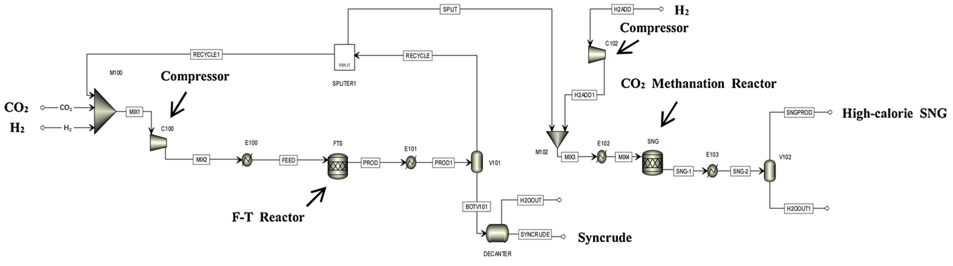
3.1.2. Direct Power-to-Syncrude Process

In the direct process, CO2 is hydrogenated directly to generate syncrude via FTS (see Equation (7)). It is well known that CO2 is a very stable chemical molecule. Hence, more efficient catalysts are necessary to achieve direct CO2 hydrogenation. At present, some researchers proposed that modified Fe-based catalysts are crucial for direct CO2 hydrogenation [97]. In addition to the catalysts, it should be noted that the operating temperature of the direct process is generally at 300–350 °C [92].
Kamkeng et al. proposed a novel direct power-to-syncrude process configurated with ex situ water removal devices. Compared with the traditional power-to-syncrude process, the application of the ex situ water removal devices further enhances the CO2 conversion and gasoline yield by 36% and 27%, respectively [98]. Moreover, Zhang et al. proposed a completed PTL/PTG hybrid process based on the direct conversion of CO2 to syncrude and conducted the process modeling, as shown in Figure 7. They combined the power-to-syncrude process with the Fe-based FTS and methanation process, and achieved the co-production of syncrude and high-calorie SNG. The technical analysis showed that the energy efficiency and the CO2 reduction rate were 76% and 94%, respectively [99]. Based on the previous work, Gao et al. developed two indirect PTL/PTG hybrid processes combined with RWGS and Fe/Co-based FTS, as presented in Figure 8, and compared direct and indirect processes from the technical aspect. For the indirect hybrid process with Fe-based FTS, the energy efficiency and CO2 reduction rate were 70% and 88%, respectively. For the indirect hybrid process with Co-based FTS, the energy efficiency and CO2 reduction rate were 73% and 90%, respectively. Therefore, based on the aforementioned results, the direct process has a higher energy efficiency and CO2 reduction potential in comparison to the indirect processes [100,101].

3.1.3. Process Integration via the Efficient Utilization of Light Hydrocarbons

The crude product of direct and indirect processes includes unreacted CO, H2, CO2, and other C1–C4 light hydrocarbons. In the case of a Fe-based catalyst, CO, H2, and CO2 can be recycled directly to the FTS unit. In the case of a Co-based catalyst, CO2 needs to be recycled to the RWGS unit to convert syngas. The specific separation methods are illustrated in Section 2.4. In addition to unreacted gases, numerous reviewers have been preoccupied with the efficient utilization of C1–C4 light hydrocarbons. At present, there are three primary integrated processes to achieve the full recovery and utilization of C1–C4 light hydrocarbons: reforming, combustion, and the production of high-calorie SNG.
(1) Syngas production via reforming
Light hydrocarbons are equivalent to inert components and are not conducive to FTS. Generally, C1–C4 light hydrocarbons are reformed into syngas in a reformer or gasification unit, and then recycled to the FTS reactor [100,102]. In addition, some researchers have proposed new integrated processes. For example, Cinti et al. sent C1–C4 light hydrocarbons to the SOEC cell, and they found that the reforming reaction can occur under the operating conditions of SOECs (750 °C, Ni-based catalyst and large amounts of steam) [103]. Although this work reduces the complexity of the system, the electrode material can poison due to carbon deposition.
(2) Heat generation via combustion
This method aims to regard light hydrocarbon as fuel. The heat generated by fuel combustion can be a utility to provide energy for the system. For example, König [93,104] and Adelung [105] et al. used C1–C4 hydrocarbons as fuel and burned them with O2 from water electrolysis, obtaining steam. It can heat the feedstock of the RWGS unit and provide heat for the RWGS reaction. Although the method reduces the dependence of the operating unit on external energy to some extent, it does not realize the high-value utilization of C1–C4 hydrocarbons.
(3) High-calorie SNG production via process integration
As highlighted above, the significant weakness of the traditional natural gas and SNG is the low energy density and calorific value. However, they can be improved by increasing the composition of C2–C4 hydrocarbons because the energy density of hydrocarbons increases as the carbon number increases [106]. Therefore, the process integration of FTS and methanation is very promising. For example, Zhang et al. proposed a PTL/PTG hybrid process and conducted the process modeling. The process aims to send unreacted CO, CO2, H2, and C1–C4 hydrocarbons in the crude product to the methanation unit and obtain high-calorie SNG. Compared with the traditional PTL process, the hybrid PTL/PTG process has a higher net CO2 reduction and lower net CO2 reduction costs [99].
(4) Syncrude production via the olefin oligomerization
The light hydrocarbons generally consist a large portion of C2–C4 olefins, which can be further converted to the high value-added syncrude over the modified HZSM-5 catalyst [107]. With this in mind, Zhang et al. proposed hybrid PTL/PTG processes integrated with FTS and oligomerization technologies, and compared their techno-economic performances with the hybrid PTL/PTG processes with single FTS technology. It was found that the application of the oligomerization reactor significantly improves the syncrude production and techno-economic competitiveness [21,108].

3.1.4. Production Cost Analysis

The power-to-syncrude process is feasible from the technical aspect, but most plants based on the power-to-syncrude process remain on the level of small-scale demonstration. Norsk e-Fuel plans to establish Europe’s first commercial power-to-syncrude plant to produce renewable fuels in Norway [109]. From the economic aspect, the product cost of indirect and direct processes is higher than the market price. First, we take the indirect processes as an example for production cost analysis. Tremel et al. conducted an economic analysis of FTS. They found that the F-T syncrude was not economically viable under the current process conditions. The production cost was 2.01 EUR/kg, which was 3–4 times higher compared with conventional fossil fuels [110]. Moreover, Adelung et al. optimized the operating conditions of the RWGS reactor to further reduce the net production cost of the indirect process. The results indicated that the minimum net production cost was 1.81 EUR/kgC5+ hydrocarbons [111]. Cuéllar-Franca et al. found that the main reason for the high cost of F-T fuels is hydrogen production via water electrolysis [112]. Decker et al. also presented a similar conclusion. They found that the H2 production cost accounts for 70–80% of total production cost [113]. Herz et al. compared the economic performances of the indirect power-to-syncrude processes integrated with different water electrolysis technologies. It was found that the net production cost of the SOEC-based PTL process was lower than that of the PEM-based PTL process by 0.059 EUR2020/kWhch [109]. With the large-scale deployment of renewable energy and improvements in CO2 capture and water electrolysis technologies, Drünert et al. estimated that the net fuel production cost of PTL kerosene can be reduced to 1.8–2.6 EUR/L in 2030, and its cost is expected to further reduce to 1.4–2.5 EUR/Lfuel in 2050 [114]. For the direct process, Zhang et al. estimated the production cost based on the direct PTL/PTG hybrid process. The total syncrude production cost was 202.58–210.56 USD/bbl [99]. Gao et al. conducted an economic assessment of the indirect processes with Fe/Co-based FTS. For the indirect process with Fe-based FTS, the total syncrude production cost was 225.65–239.12 USD/bbl, while for the indirect process with Co-based FTS, the total syncrude production cost was 215.80–219.18 USD/bbl [100,101]. Moreover, Colelli et al. also compared with the economic performances of the indirect and direct processes. It was found that the product cost of the indirect processes was 460~1435 EUR/bbl, whereas the product cost of the direct processes was 752~2364 EUR/bbl. It should be noted that Colelli et al. did not consider the recovery of the unreacted syngas; therefore, the direct process with lower CO2 conversions had a relatively higher product cost [115]. In addition, considering the fact that water electrolysis technologies could affect the total production cost, we explored the effect of the different water electrolysis technologies on the total production cost of the hybrid PTL/PTG processes. It was found that the hybrid PTL/PTG process coupled with AEM water electrolysis technology has the lowest total production cost [21,116].
CO 2 ( g ) + H 2 ( g ) CO ( g ) + H 2 O ( g )   Δ r H m θ = 42.1   kJ / mol  
n · CO ( g ) + 2 n · H 2 ( g ) ( - CH 2 - ) n ( l ) + n · H 2 O ( g )   Δ r H m   θ = 152   kJ / mol  
CO ( g ) + 3 H 2 ( g ) CH 4 ( g ) + H 2 O ( g )   Δ r H m θ = 207.0   kJ / mol  
CO ( g ) + H 2 O ( g ) CO 2 ( g ) + H 2 ( g )   Δ r H m θ = 42.1   kJ / mol  
CO 2 ( g ) + 2 H 2 O ( g ) electricity CO ( g ) + 2 H 2 ( g ) + 3 2 O 2 ( g )     Δ r H m θ = 525.1   kJ · mol 1  
n · CO 2 ( g ) + 3 n · H 2 ( g ) ( - CH 2 - ) n ( l ) + 2 n · H 2 O ( g )   Δ r H m θ = 125   kJ / mol  

3.2. Power-to-Methanol Process

Power-to-methanol process mainly aims to convert water and CO2 into methanol, which is an important platform chemical. Based on methanol, organic products such as formaldehyde, formic acid, dimethyl ether, acetic acid, and methyl tert-butyl ether(MTBE) can be produced [117,118]. Although the volumetric energy density of methanol is only half that of gasoline, the octane number of methanol is higher. Hence, methanol can be mixed with gasoline, improving gasoline quality [78].

3.2.1. Methanol Synthesis via CO2 Hydrogeneration

For the power-to-methanol process, methanol synthesis is a crucial step. Generally, CO2 and H2 can be directly converted into methanol over a commercial Cu/ZnO/Al2O3 catalyst (see Equation (8)). The typical operating temperature and pressure are 250–300 °C and 5–10 MPa, respectively [119]. Moreover, the H2/CO2 ratio in the feedstock is generally controlled at about 3 [120]. Generally, the per pass CO2 conversion is about 26% with commercially available catalysts due to the limitation of thermodynamic equilibrium [121]. However, the total CO2 conversion can be improved by recycling the unreacted gas and multiple reactors in series, which are briefly introduced in the following content.
(1) Enhancement of CO2 conversion by recycling the unreacted gas
Recycling the unreacted gas is a typical way to improve total CO2 conversion. For example, in the methanol synthesis process by Pérez-Fortes et al., 99% of unreacted gas mainly composed of H2 and carbon oxides was recycled to the reactor, and 1% of unreacted gas was purged to avoid the accumulation of inert gases. It was found that the total CO2 conversion in the process was 94%, while per pass CO2 conversion was 22% [122]. Leonzio et al. used three different reactor configurations, including a once-through reactor, a reactor with the recycling of unreacted gases after the separation of methanol and water, and a membrane reactor with in situ water removal (See Figure 9). In addition, they compared the effect of different reactors on CO2 conversion. The results showed that the total CO2 conversion of the three reactors were 40%, 79%, and 60% at 493 K and 55 bar (recycle ratio = 0.8). The methanol selectivity of the three reactors were 96%, 88%, and 96% at the same operating conditions. Therefore, It should be noted that recycling unreacted gases can improve total CO2 conversion, but decreases methanol selectivity slightly [123].
(2) Enhancement of CO2 conversion by multiple reactors in series
Wiesberg et al. proposed the methanol synthesis process with two-stage reactors in series and conducted the process modeling. In the first stage, CO2 is partially converted into methanol at a lower pressure. In the second stage, the unreacted CO2 is converted into methanol under higher pressure. The total CO2 conversion was 98.5% [124]. Moioli et al. investigated the influence of the number of stages on the space time yield and methanol yield in the case of selected catalysts, and determined that the optimal number of stages was three [125]. In addition, Samimi et al. used three-stage reactors of water permselective membrane in series for methanol production. They found that compared with a one-stage reactor, the novel reactor configuration caused the CO2 conversion to increase by about 50% [126].

3.2.2. Process Integration of Methanol Synthesis and H2O/CO2 Co-Electrolysis

Process integration of power-to-methanol and H2O/CO2 co-electrolysis is a promising technology to achieve the efficient utilization of energy. First, CO2 and H2O are converted into syngas via co-electrolysis in the high-temperature SOEC cell, and then the syngas is used as the feedstock of methanol synthesis, as shown in Figure 10. For example, Al-Kalbani et al. compared the integrated process and the direct CO2 hydrogenation process. They found that the energy efficiency of the integrated process was 41%, which is almost 2 times higher compared with that of the CO2 hydrogenation process [127]. Hankin et al. evaluated the technical performance of four different methanol production processes. It was found that the methanol production integrated with the high-temperature co-electrolysis of H2O and CO2 is the best technology from the aspect of energy consumption and CO2 conversion [128]. In addition, Zhang et al. developed a complete power-to-methanol process combined with CO2 and H2O co-electrolysis technology and conducted the process modeling. Moreover, they burned inert components (methane and ethers) in the boiler, and recovered waste heat in the form of steam. The results showed that the system energy efficiency was 72% [129].

3.2.3. Product Purification

The crude methanol obtained by power-to-methanol process contains water, dissolved gases, and higher alcohols, and it needs to be further purified and upgraded to meet the requirement of fuel-grade methanol (>99 wt%) [130,131]. Generally, A widely used separation process is the combination of gas–liquid separators and distillation columns. The gas–liquid separators are used to remove most water and dissolved gas, such as CO, CO2, and H2. The distillation columns further remove impurities in the crude methanol, such as dimethyl ether (DME), methyl formate, other hydrocarbons, and alcohols [124,132]. However, the traditional distillation technologies are energy-intensive and cost-intensive. Therefore, the emerging membrane distillation technologies and pervaporation technologies have also been developed to achieve the efficient separation of the methanol and water [133]. Nevertheless, the purity of the product obtained via the emerging technologies still need to be further improved. Meanwhile, these novel technologies still have a long way before achieving large-scale industrialization.

3.2.4. Production Cost Analysis

The power-to-methanol process is feasible from the technical aspect, and some small- and medium-scale demonstration plants are currently in operation. For example, Carbon Recycling International operates a medium-scale demonstration plant in Iceland, and its production capacity is 4000 tons/year [134,135]. However, from an economic aspect, the production cost of methanol via the power-to-methanol process is currently not attractive. For example, Atsonios et al. conducted an economic analysis of the methanol production cost of CO2 hydrogenation, and found that the methanol cost via power-to-methanol process is 2.5 times compared with that of traditional methanol [136]. Adnan et al. compared three novel power-to-methanol processes from the economic aspect, and the results presented showed that the levelized methanol cost was 860–1585 USD/tons when the electricity price was 0.04 USD/kWh, which was 2–4 times higher than the market prices (300–500 USD/tons) [137]. Sollai et al. conducted a techno-economic assessment of the power-to-methanol processes. As a result, the levelized cost of the methanol was 960 EUR/t, which was two times more than the current methanol price in the international market [138]. Do et al. developed a novel methanol production process based on the sunshine-to-petrol framework and conducted an economic analysis. The results presented that the minimum selling price of methanol was 0.94 USD/kg [139]. Rivera-Tinoco et al. conducted an economic performance analysis of power-to-methanol processes combined with PEM technology and SOEC technology. The results showed that the methanol costs were 891 EUR/tons and 5459 EUR/tons, respectively [140]. Kourkoumpas et al. investigated the methanol production cost of the power-to-methanol process in Greece and Germany. In Greece, the production cost was 421–580 EUR/tons, while in Germany, the production cost was 342 EUR/tons due to lower electricity costs [141]. Cordero-Lanzac et al. suggested that reducing the H2 price and increasing the carbon taxation could further enhance the economic competitiveness of the methanol production cost. More specifically, when the H2 price decreased to 1.5 USD/kg and the carbon taxation increased to 300 USD/tons, the power-to-methanol process could be profitable [142].
Nizami et al. conducted an economic analysis of power-to-methanol processes using solar energy, and found that the production cost of methanol was 1040.17 USD/tons [143]. Bos et al. evaluated the methanol production process using 100 MW stand-alone wind power, and found that the production cost of methanol was 750–800 USD/tons [144]. Gu et al. proposed three power-to-methanol processes coupled with wind, solar, and wind–solar energy. The results indicated that their production costs of methanol were 531.4 USD/tons, 889.5 USD/tons MeOH, and 488.5 USD/tons, respectively [145]. Overall, the power-to-methanol process using the solar energy has the highest production cost due to expensive solar panels [146]. The production cost of the power-to-methanol processes using different renewable energy are listed in Table 2.
CO 2 ( g ) + 3 H 2 ( g ) cat . CH 3 O   H ( g ) + H 2 O ( g )   Δ r H m θ = 49.4   kJ / mol  

3.3. Power-to-Ethers Process

3.3.1. Power-to-DME Process

DME is currently regarded as a clean synthetic fuel. Compared with traditional diesel fuel, DME has a higher cetane number, higher oxygen content, and no C–C bond. Moreover, its combustion generally produces less particulate matter, smoke, and CO [147]. In addition, DME is an important platform chemical, which can be efficiently converted into acetic acid, ethanol, methyl acetate, and aromatics [148]. Generally, the power-to-DME process can be classified into either an indirect or a direct one, which are briefly introduced in the following content.
(1) Indirect power-to-DME process
For the indirect power-to-DME process, CO2 and H2 are first converted into methanol, which are further dehydrated to obtain DME over acidic catalysts such as γ-Al2O3 and HZSM-5 zeolites and ion exchange resins (see Equation (9)) [149,150]. The operating temperature is 220–250 °C, and the operating pressure is 10–20 bar [148]. The thermodynamic equilibrium limits the methanol conversion, and the crude product likely contains unreacted methanol, which results in subsequent complex separation steps [151]. Hence, the total methanol conversion needs to be further improved by the following ways, such as recycling the unreacted methanol and reactive distillation (RD). For example, Michailos et al. separated the methanol from the crude product via distillation and recycled it to the DME reactor. The results showed that the total methanol conversion reached 99.9%, and the total CO2 conversion reached 82.3% [152]. In addition, RD based on process intensification principles is becoming an emerging research hotspot. The RD aims to further improve the process performance limited by the equilibrium and reduce energy consumption and economic cost. For instance, Bîldea et al. developed a novel reactor-separation-recycle process combined with RD, as shown in Figure 11. The process achieved the complete conversion of methanol. In addition, 6% of the specific energy requirements and 30% of CAPEX were reduced [153].
(2) Direct power-to-DME process
For the direct power-to-DME process, CO2 is directly hydrogenated to synthesize DME over bifunctional catalysts, such as Cu–Zn–Zr/zeolite (see Equation (10)) [154]. Methanol synthesis and subsequent dehydration steps are conducted in the same reactor, which saves the equipment cost from the economic aspect [155]. In addition, in situ methanol generation and consumption can contribute to breaking the thermodynamic limitation of methanol synthesis, which can be carried out at higher temperatures and lower pressures [148,156]. Chen et al. compared direct and indirect processes from the thermodynamic perspective, and found that the direct process had a lower thermodynamic limitation than the indirect process and a higher selectivity and yield [157]. Similar to the indirect process, recycling unreacted H2 and CO2 can further increase DME production. For example, Kartohardjono et al. compared the effect of the different recycling amounts on DME production. It was found that the DME production increased by 65.1% when the recycling amount increased by 70% [158]. Moreover, Zhang et al. compared the technical performances of the direct and indirect processes. It was found that the direct process had higher energy efficiency, exergy efficiency, and net CO2 mitigation rate due to the lack of the energy-intensive distillation and evaporation unit [159].
(3) Process performance enhancement
Both the direct and the indirect processes produce a considerable amount of by-product water. Especially for the direct process, the issue is more serious. A small amount of water can attenuate the coke deposition [160], but as the water content increases, the catalyst activity is inhibited, resulting in a decrease in CO2 conversion and DME yield [161,162]. Hence, it is necessary to remove water to enhance process performance in time. Peinado et al. used 3A zeolite to remove water in situ. The results showed that the DME productivity was 2 times higher than that of the process without 3A zeolite [163]. Kampen et al. used the same adsorbent and developed a sorption enhanced DME synthesis process combined with pressure swing adsorption. It was found that the DME productivity was 4 times higher than the traditional DME process without PSA [164]. Ateka et al. used H2O permeation selective membranes (H-SOD-type zeolite membranes) to remove H2O in situ, and the CO2 conversion and yield reached 70% and 60%, respectively [165]. De Falco et al. designed a staged membrane reactor composed of multiple conventional reactors and selective membrane modules in series [166]. Unlike the aforementioned in situ removal of H2O, the staged membrane reactor separates the membrane from the reactor and removes H2O after each reactor. Therefore, the membrane can be prevented from being affected by improper operating conditions.
Indirect process: methanol is obtained through Equation (8).
2 CH 3 OH ( g ) cat . CH 3 OCH 3 ( g ) + H 2 O ( g )   Δ r H m θ = 23.4   kJ / mol  
Direct process:
2 CO 2 ( g ) + 6 H 2 ( g ) cat . CH 3 OCH 3 ( g ) + 3 H 2 O ( g )   Δ r H m θ = 120.8   kJ / mol  

3.3.2. Power-to-OMEn Process

The oxymethylene ether (OMEn) with the molecular structure of CH3O(CH2O)nCH3, which is produced by the catalytic conversion of H2 and CO2, is attracting increasing interest from academic research and industry [167,168]. Most of the research on OMEn primarily focuses on OME3–5, which are promising oxygenated fuels, and their physicochemical properties performance is similar to traditional diesel. However, the combustion of OME3–5 generally produces less soot formation and hazardous exhaust gas than traditional diesel due to an absence of a C–C bond [169,170].
Generally, the synthetic routes of OMEn can be classified into two categories, A and B. In route A, methanol and formaldehyde (FA) undergo condensation reactions (see Equation (14)) over an acidic catalyst such as ion exchange resin, obtaining OMEn [171]. In route B, methanol reacts with FA to produce methylal (MAL) (see Equation (13)), which further reacts with trioxane (TRI) over the zeolite to obtain OMEn (see Equation (15)) [172].
The similarity between the two routes is that intermediate methanol and FA are essential. Methanol is oxidized partially (see Equation (11)) or dehydrogenated directly (see Equation (12)) over a silver catalyst, obtaining FA [173]. Especially for the direct dehydrogenation of methanol, the product H2 needs to be recycled, thus decreasing the electricity demand of the electrolysis [174].
There are differences between these two routes. Route A generates a large amount of water in comparison with route B, which reduces the selectivity of OMEn. The byproduct water can be removed via membranes, such as zeolite membranes, but it increases equipment investment simultaneously [175,176]. TRI in route B has high production complexity, high energy consumption, low yield, and high price [177,178]. Additionally, route B requires more operating units than route A, which requires a higher capital expenditure. From the aspect of energy efficiency, Held et al. compared route A and route B from the perspective of system efficiency and heat integration. They found that the efficiency of route A was 31.3–36.3%, while the efficiency of route B was 29.2–36.7% [174].

3.3.3. Production Cost Analysis

From the economic aspect, the power-to-ethers process is not feasible under current technical conditions. For example, Michailos et al. conducted an economic assessment of the power-to-DME process, and found that the minimum DME selling price was 1828–2322 EUR/tons, which was 4.5–5.7 times more compared with fossil diesel’s gate price [152]. Hepburn et al. estimated that the production cost of DME was 2.74 USD/kg DME, which exceeds the market price (0.66 USD/kg) [179]. In fact, the production cost of DME is related to the production scale. Skorikova et al. estimated that the production cost of DME was about 1.55 USD/kg DME when the DME production rate was 23 kt/year [180]. Martín et al. found that the production cost of DME was 1.4 USD/kg DME when the production scale of DME increased to 197 kt/year [181]. In our previous work, we compared the economic performances of the direct and indirect DME synthesis processes. The results indicated that the direct process had a lower total product cost [159]. For an economic analysis of OMEn, Rodríguez-Vallejo et al. compared the economic performance of different OME3–5 production ways, and they found that the total monetized cost of OME3–5 fuel is 1.5–3.6 times more compared with that of conventional diesel [182].
CH 3 OH + 1 2 O 2 Ag CH 2 O + H 2 O  
CH 3 OH Ag CH 2 O + H 2  
2 CH 3 OH + CH 2 O cat . CH 3 OCH 2 OCH 3 + H 2 O  
2 CH 3 OH + nCH 2 O cat . CH 3 O ( CH 2 O ) n CH 3 + H 2 O  
CH 3 OCH 2 OCH 3 + n 1 3 ( CH 2 O ) 3 cat . CH 3 O ( CH 2 O ) n CH 3  

4. Conclusions and Prospect

4.1. Conclusions

To mitigate climate change, it is necessary to take measures to reduce CO2 emissions. PTG and PTL are promising processes that can significantly reduce CO2 emissions and produce valuable chemical products. In this review, we have critically and comprehensively summarized the recent research progresses of PTG and PTL processes from the technical and economic aspects. Herein, we mainly focus on the power-to-methane process in the case of PTG and the power-to-syncrude, power-to-methanol, and power-to-ethers processes in the case of PTL.
In the power-to-methane processes, we mainly studied the effects of the operating conditions (i.e., operating temperature and operating pressure) and reactor configurations (i.e., fixed-bed, fluidized-bed, three-phase, and structured reactors) on the process performances of CO2 methanation. Moreover, considering that the CO2 and water impurities in the crude SNG could cause damage to the transportation equipment, some typical product purification technologies, such as absorption, adsorption, and membrane separation, have been widely applied. Furthermore, the integration process of CO2 methanation and H2O/CO2 co-electrolysis has become the research emphasis due to the reduction in the dependence of the coupled system on external energy. In addition, it was found that the production cost of SNG is still 2–7 times higher compared with the cost of traditional natural gas.
In the power-to-syncrude processes, the research progress of indirect and direct pathways were summarized. For the indirect pathway, the traditional RWGS and emerging H2O and CO2 co-electrolysis technologies have been used to produce the syngas. Moreover, we further illustrated and compared the differences between the Fe-based and Co-based FTS routes to convert the syngas into the syncrude. For the direct pathway, it showed a stronger competitiveness compared to the indirect pathways in terms of energy utilization and carbon mitigation potential. Furthermore, we summarized four technologies to achieve the efficient utilization of the light hydrocarbons in the FTS reaction, namely reforming them to syngas, combusting them to provide heat, converting them to high-calorie SNG, and transforming them to syncrude. Lastly, it was found that the production cost of syncrude is 3–4 times higher compared with conventional fossil fuels. In the power-to-methanol processes, the CO2 conversion over commercially available catalysts was limited by the thermodynamic equilibrium. Recovering the unreacted syngas and adopting multiple reactors in series can further improve CO2 conversion. Similar to the production cost of the syncrude, the production cost of the methanol obtained via the power-to-methanol process is also 3–4 times higher compared with that of traditional methanol. In the power-to-ethers processes, DME and OMEn are primary products. For the power-to-DME processes, the differences between the indirect and direct routes are compared in detail. Moreover, the adsorption and membrane separation methods were proposed to remove the byproduct water and enhance the process performance. For the power-to-OMEn processes, we briefly reviewed the relevant production pathways and summarized the differences between these pathways. In addition, the production costs of DME and OMEn were 4–6 times and 1–4 times higher compared with fossil diesel, respectively.

4.2. Prospect

From the technical aspect, the major challenge of PTG and PTL processes is the low system efficiency, which can be improved via heat integration and/or process integration. For instance, the heat released from reaction and/or the combustion of inert compacts can be used to generate the steam required by co-electrolysis. The extra heat can be used to regenerate solvent in the CO2 capture process or generate power through the Rankine cycle. In addition, the CO2 conversion, product yield, and selectivity are concerns of academia and industry, which can be improved by the process integration of reaction and in situ product separation, the development of more efficient catalysts, and the investigation of the reaction mechanism.
From the economic aspect, the production cost of green products from PTG and PTL considerably exceeds the cost of conventional fossil fuels. Among the various factors, H2 production is the primary factor, which can be reduced by the following ways, such as improving electrolysis efficiency and reducing electricity price. First, the electrolysis efficiency can be improved by developing novel water electrolysis technologies with a higher electrolysis efficiency, such as anion exchange membrane and solid oxide water electrolysis technologies. Moreover, increasing the current density, reducing the membrane thickness, and using a more efficient electrode material are also expected to further improve electrolysis efficiency. The deployment scale of renewable energy significantly affects the electricity price. In addition, the carbon tax has a significant effect on the PTG and PTL processes. High carbon tax contributes to improving the economic competitiveness of the PTG and PTL processes. In addition, the government should formulate incentive policies to stimulate more enterprises to produce green commodities effectively.

Author Contributions

Conceptualization, Z.T. and L.Z.; methodology, R.G.; validation, L.W. and X.L.; formal analysis, R.G.; investigation, Z.T.; resources, C.Z.; writing—original draft preparation, R.G.; writing—review and editing, C.Z.; visualization, L.Z.; supervision, C.Z.; project administration, C.Z.; funding acquisition, C.Z. All authors have read and agreed to the published version of the manuscript.

Funding

This work was supported by the “Next Generation Carbon Upcycling Project” (Project No. 2017M1A2A2043133) through the National Research Foundation (NRF) funded by the Ministry of Science and ICT, Republic of Korea. We also appreciate the Natural Science Foundation of Jiangsu Province (BK20200694, 20KJB530002, and 21KJB480014), the Jiangsu Specially Appointed Professors Program, and the open program of the State Key Laboratory of High-efficiency Utilization of Coal and Green Chemical Engineering (2021–K32).

Data Availability Statement

All the data are presented in the manuscript.

Conflicts of Interest

The authors declare no conflict of interest.

References

  1. IEA. CO2 Emissions in 2022. Available online: https://www.iea.org/reports/co2-emissions-in-2022 (accessed on 23 June 2023).
  2. Li, X.; Xiong, S.; Li, Z.; Zhou, M.; Li, H. Variation of global fossil-energy carbon footprints based on regional net primary productivity and the gravity model. J. Clean. Prod. 2019, 213, 225–241. [Google Scholar] [CrossRef]
  3. Peters, G.P.; Andrew, R.M.; Canadell, J.G.; Friedlingstein, P.; Jackson, R.B.; Korsbakken, J.I.; Le Quéré, C.; Peregon, A. Carbon dioxide emissions continue to grow amidst slowly emerging climate policies. Nat. Clim. Chang. 2020, 10, 3–6. [Google Scholar] [CrossRef]
  4. Hernández, S.; Amin Farkhondehfal, M.; Sastre, F.; Makkee, M.; Saracco, G.; Russo, N. Syngas production from electrochemical reduction of CO2: Current status and prospective implementation. Green Chem. 2017, 19, 2326–2346. [Google Scholar] [CrossRef] [Green Version]
  5. Horton, B.P.; Rahmstorf, S.; Engelhart, S.E.; Kemp, A.C. Expert assessment of sea-level rise by AD 2100 and AD 2300. Quat. Sci. Rev. 2014, 84, 1–6. [Google Scholar] [CrossRef]
  6. Pachauri, R.K.; Allen, M.R.; Barros, V.R.; Broome, J.; Cramer, W.; Christ, R.; Church, J.A.; Clarke, L.; Dahe, Q.; Dasgupta, P. Climate Change 2014: Synthesis Report. Contribution of Working Groups I, II and III to the Fifth Assessment Report of the Intergovernmental Panel on Climate Change; IPCC: Geneva, Switzerland, 2014. [Google Scholar]
  7. Dowling, J.A.; Rinaldi, K.Z.; Ruggles, T.H.; Davis, S.J.; Yuan, M.; Tong, F.; Lewis, N.S.; Caldeira, K. Role of Long-Duration Energy Storage in Variable Renewable Electricity Systems. Joule 2020, 4, 1907–1928. [Google Scholar] [CrossRef]
  8. Gabrielli, P.; Gazzani, M.; Mazzotti, M. The Role of Carbon Capture and Utilization, Carbon Capture and Storage, and Biomass to Enable a Net-Zero-CO2 Emissions Chemical Industry. Ind. Eng. Chem. Res. 2020, 59, 7033–7045. [Google Scholar] [CrossRef] [Green Version]
  9. Ho, H.-J.; Iizuka, A.; Shibata, E. Carbon Capture and Utilization Technology without Carbon Dioxide Purification and Pressurization: A Review on Its Necessity and Available Technologies. Ind. Eng. Chem. Res. 2019, 58, 8941–8954. [Google Scholar] [CrossRef]
  10. Parekh, A.; Chaturvedi, G.; Dutta, A. Sustainability analyses of CO2 sequestration and CO2 utilization as competing options for mitigating CO2 emissions. Sustain. Energy Technol. Assess. 2023, 55, 102942. [Google Scholar] [CrossRef]
  11. Kamkeng, A.D.N.; Wang, M.; Hu, J.; Du, W.; Qian, F. Transformation technologies for CO2 utilisation: Current status, challenges and future prospects. Chem. Eng. J. 2021, 409, 128138. [Google Scholar] [CrossRef]
  12. Kim, C.; Yoo, C.-J.; Oh, H.-S.; Min, B.K.; Lee, U. Review of carbon dioxide utilization technologies and their potential for industrial application. J. CO2 Util. 2022, 65, 102239. [Google Scholar] [CrossRef]
  13. Mendoza, J.M.F.; Ibarra, D. Technology-enabled circular business models for the hybridisation of wind farms: Integrated wind and solar energy, power-to-gas and power-to-liquid systems. Sustain. Prod. Consum. 2023, 36, 308–327. [Google Scholar] [CrossRef]
  14. Ozturk, M.; Dincer, I. A comprehensive review on power-to-gas with hydrogen options for cleaner applications. Int. J. Hydrogen Energy 2021, 46, 31511–31522. [Google Scholar] [CrossRef]
  15. Götz, M.; Lefebvre, J.; Mörs, F.; McDaniel Koch, A.; Graf, F.; Bajohr, S.; Reimert, R.; Kolb, T. Renewable Power-to-Gas: A technological and economic review. Renew. Energy 2016, 85, 1371–1390. [Google Scholar] [CrossRef] [Green Version]
  16. Rafiee, A.; Panahi, M.; Khalilpour, K.R. CO2 utilization through integration of post-combustion carbon capture process with Fischer-Tropsch gas-to-liquid (GTL) processes. J. CO2 Util. 2017, 18, 98–106. [Google Scholar] [CrossRef]
  17. Ra, E.C.; Kim, K.Y.; Kim, E.H.; Lee, H.; An, K.; Lee, J.S. Recycling Carbon Dioxide through Catalytic Hydrogenation: Recent Key Developments and Perspectives. ACS Catal. 2020, 10, 11318–11345. [Google Scholar] [CrossRef]
  18. Aubin, P.; Wang, L.; Van herle, J. Evaporating water-cooled methanation reactor for solid-oxide stack-based power-to-methane systems: Design, experiment and modeling. Chem. Eng. J. 2023, 456, 140256. [Google Scholar] [CrossRef]
  19. Gao, J.; Wang, Y.; Ping, Y.; Hu, D.; Xu, G.; Gu, F.; Su, F. A thermodynamic analysis of methanation reactions of carbon oxides for the production of synthetic natural gas. RSC Adv. 2012, 2, 2358–2368. [Google Scholar] [CrossRef]
  20. Saeidi, S.; Najari, S.; Hessel, V.; Wilson, K.; Keil, F.J.; Concepción, P.; Suib, S.L.; Rodrigues, A.E. Recent advances in CO2 hydrogenation to value-added products—Current challenges and future directions. Prog. Energy Combust. Sci. 2021, 85, 100905. [Google Scholar] [CrossRef]
  21. Gao, R.; Zhang, L.; Wang, L.; Zhang, C.; Jun, K.-W.; Kim, S.K.; Park, H.-G.; Zhao, T.; Wan, H.; Guan, G. Efficient utilization of CO2 in power-to-liquids/power-to-gas hybrid processes: An economic-environmental assessment. J. CO2 Util. 2023, 68, 102376. [Google Scholar] [CrossRef]
  22. Bassano, C.; Deiana, P.; Lietti, L.; Visconti, C.G. P2G movable modular plant operation on synthetic methane production from CO2 and hydrogen from renewables sources. Fuel 2019, 253, 1071–1079. [Google Scholar] [CrossRef]
  23. Dannesboe, C.; Hansen, J.B.; Johannsen, I. Catalytic methanation of CO2 in biogas: Experimental results from a reactor at full scale. React. Chem. Eng. 2020, 5, 183–189. [Google Scholar] [CrossRef] [Green Version]
  24. Rönsch, S.; Schneider, J.; Matthischke, S.; Schlüter, M.; Götz, M.; Lefebvre, J.; Prabhakaran, P.; Bajohr, S. Review on methanation—From fundamentals to current projects. Fuel 2016, 166, 276–296. [Google Scholar] [CrossRef]
  25. Koytsoumpa, E.I.; Karellas, S. Equilibrium and kinetic aspects for catalytic methanation focusing on CO2 derived Substitute Natural Gas (SNG). Renew. Sustain. Energy Rev. 2018, 94, 536–550. [Google Scholar] [CrossRef]
  26. Iaquaniello, G.; Setini, S.; Salladini, A.; De Falco, M. CO2 valorization through direct methanation of flue gas and renewable hydrogen: A technical and economic assessment. Int. J. Hydrogen Energy 2018, 43, 17069–17081. [Google Scholar] [CrossRef]
  27. Schaaf, T.; Grünig, J.; Schuster, M.R.; Rothenfluh, T.; Orth, A. Methanation of CO2—Storage of renewable energy in a gas distribution system. Energy Sustain. Soc. 2014, 4, 2. [Google Scholar] [CrossRef] [Green Version]
  28. Kopyscinski, J.; Schildhauer, T.J.; Biollaz, S.M.A. Production of synthetic natural gas (SNG) from coal and dry biomass—A technology review from 1950 to 2009. Fuel 2010, 89, 1763–1783. [Google Scholar] [CrossRef]
  29. Hervy, M.; Maistrello, J.; Brito, L.; Rizand, M.; Basset, E.; Kara, Y.; Maheut, M. Power-to-gas: CO2 methanation in a catalytic fluidized bed reactor at demonstration scale, experimental results and simulation. J. CO2 Util. 2021, 50, 101610. [Google Scholar] [CrossRef]
  30. Younas, M.; Loong Kong, L.; Bashir, M.J.K.; Nadeem, H.; Shehzad, A.; Sethupathi, S. Recent Advancements, Fundamental Challenges, and Opportunities in Catalytic Methanation of CO2. Energy Fuels 2016, 30, 8815–8831. [Google Scholar] [CrossRef]
  31. Lefebvre, J.; Götz, M.; Bajohr, S.; Reimert, R.; Kolb, T. Improvement of three-phase methanation reactor performance for steady-state and transient operation. Fuel Process. Technol. 2015, 132, 83–90. [Google Scholar] [CrossRef]
  32. Sauerschell, S.; Bajohr, S.; Kolb, T. Methanation Pilot Plant with a Slurry Bubble Column Reactor: Setup and First Experimental Results. Energy Fuels 2022, 36, 7166–7176. [Google Scholar] [CrossRef]
  33. Brooks, K.P.; Hu, J.; Zhu, H.; Kee, R.J. Methanation of carbon dioxide by hydrogen reduction using the Sabatier process in microchannel reactors. Chem. Eng. Sci. 2007, 62, 1161–1170. [Google Scholar] [CrossRef]
  34. Danaci, S.; Protasova, L.; Lefevere, J.; Bedel, L.; Guilet, R.; Marty, P. Efficient CO2 methanation over Ni/Al2O3 coated structured catalysts. Catal. Today 2016, 273, 234–243. [Google Scholar] [CrossRef]
  35. Aartun, I.; Venvik, H.J.; Holmen, A.; Pfeifer, P.; Görke, O.; Schubert, K. Temperature profiles and residence time effects during catalytic partial oxidation and oxidative steam reforming of propane in metallic microchannel reactors. Catal. Today 2005, 110, 98–107. [Google Scholar] [CrossRef]
  36. Guilera, J.; del Valle, J.; Alarcón, A.; Díaz, J.A.; Andreu, T. Metal-oxide promoted Ni/Al2O3 as CO2 methanation micro-size catalysts. J. CO2 Util. 2019, 30, 11–17. [Google Scholar] [CrossRef]
  37. Ghaib, K. 3D CFD Simulation of Reaction Cells, Cooling Cells, and Manifolds of a Flatbed Reactor for CO2 Methanation. Chem. Eng. Technol. 2020, 43, 1994–2006. [Google Scholar] [CrossRef]
  38. Ovalle-Encinia, O.; Wu, H.-C.; Chen, T.; Lin, J.Y.S. CO2-permselective membrane reactor for steam reforming of methane. J. Membr. Sci. 2022, 641, 119914. [Google Scholar] [CrossRef]
  39. Catarina Faria, A.; Miguel, C.V.; Rodrigues, A.E.; Madeira, L.M. Modeling and Simulation of a Steam-Selective Membrane Reactor for Enhanced CO2 Methanation. Ind. Eng. Chem. Res. 2020, 59, 16170–16184. [Google Scholar] [CrossRef]
  40. Borgschulte, A.; Gallandat, N.; Probst, B.; Suter, R.; Callini, E.; Ferri, D.; Arroyo, Y.; Erni, R.; Geerlings, H.; Züttel, A. Sorption enhanced CO2 methanation. Phys. Chem. Chem. Phys. 2013, 15, 9620–9625. [Google Scholar] [CrossRef] [Green Version]
  41. Walspurger, S.; Elzinga, G.D.; Dijkstra, J.W.; Sarić, M.; Haije, W.G. Sorption enhanced methanation for substitute natural gas production: Experimental results and thermodynamic considerations. Chem. Eng. J. 2014, 242, 379–386. [Google Scholar] [CrossRef] [Green Version]
  42. Kiefer, F.; Nikolic, M.; Borgschulte, A.; Dimopoulos Eggenschwiler, P. Sorption-enhanced methane synthesis in fixed-bed reactors. Chem. Eng. J. 2022, 449, 137872. [Google Scholar] [CrossRef]
  43. Duyar, M.S.; Treviño, M.A.A.; Farrauto, R.J. Dual function materials for CO2 capture and conversion using renewable H2. Appl. Catal. B-Environ. 2015, 168–169, 370–376. [Google Scholar] [CrossRef]
  44. Miguel, C.V.; Soria, M.A.; Mendes, A.; Madeira, L.M. A sorptive reactor for CO2 capture and conversion to renewable methane. Chem. Eng. J. 2017, 322, 590–602. [Google Scholar] [CrossRef]
  45. Lehner, M.; Tichler, R.; Steinmüller, H.; Koppe, M. Power-to-Gas: Technology and Business Models; Springer: Cham, Switzerland, 2014. [Google Scholar]
  46. Becker, W.L.; Penev, M.; Braun, R.J. Production of Synthetic Natural Gas From Carbon Dioxide and Renewably Generated Hydrogen: A Techno-Economic Analysis of a Power-to-Gas Strategy. J. Energy Resour. Technol. 2018, 141, 021901. [Google Scholar] [CrossRef]
  47. Ecker, A.-M.; Klein, H.; Peschel, A. Systematic and efficient optimisation-based design of a process for CO2 removal from natural gas. Chem. Eng. J. 2022, 445, 136178. [Google Scholar] [CrossRef]
  48. Dehdari, L.; Burgers, I.; Xiao, P.; Li, K.G.; Singh, R.; Webley, P.A. Purification of hydrogen from natural gas/hydrogen pipeline mixtures. Sep. Purif. Technol. 2022, 282, 120094. [Google Scholar] [CrossRef]
  49. Caputo, F.; Cascetta, F.; Lamanna, G.; Rotondo, G.; Soprano, A. Estimation of the damage in a natural gas flow line caused by the motion of methane hydrates. J. Nat. Gas Sci. Eng. 2015, 26, 1222–1231. [Google Scholar] [CrossRef]
  50. Yu, G.; Dai, C.; Wu, L.; Lei, Z. Natural Gas Dehydration with Ionic Liquids. Energy Fuels 2017, 31, 1429–1439. [Google Scholar] [CrossRef]
  51. Dalane, K.; Hillestad, M.; Deng, L. Subsea natural gas dehydration with membrane processes: Simulation and process optimization. Chem. Eng. Res. Des. 2019, 142, 257–267. [Google Scholar] [CrossRef]
  52. Lin, H.; Thompson, S.M.; Serbanescu-Martin, A.; Wijmans, J.G.; Amo, K.D.; Lokhandwala, K.A.; Merkel, T.C. Dehydration of natural gas using membranes. Part I: Composite membranes. J. Membr. Sci. 2012, 413–414, 70–81. [Google Scholar] [CrossRef]
  53. Chauvy, R.; Dubois, L.; Lybaert, P.; Thomas, D.; De Weireld, G. Production of synthetic natural gas from industrial carbon dioxide. Appl. Energy 2020, 260, 114249. [Google Scholar] [CrossRef]
  54. Salomone, F.; Giglio, E.; Ferrero, D.; Santarelli, M.; Pirone, R.; Bensaid, S. Techno-economic modelling of a Power-to-Gas system based on SOEC electrolysis and CO2 methanation in a RES-based electric grid. Chem. Eng. J. 2019, 377, 120233. [Google Scholar] [CrossRef]
  55. Pan, Z.; Chan, W.P.; Veksha, A.; Giannis, A.; Dou, X.; Wang, H.; Lisak, G.; Lim, T.-T. Thermodynamic analyses of synthetic natural gas production via municipal solid waste gasification, high-temperature water electrolysis and methanation. Energy Convers. Manag. 2019, 202, 112160. [Google Scholar] [CrossRef]
  56. Chen, B.; Xu, H.; Ni, M. Modelling of SOEC-FT reactor: Pressure effects on methanation process. Appl. Energy 2017, 185, 814–824. [Google Scholar] [CrossRef]
  57. Er-rbib, H.; Kezibri, N.; Bouallou, C. Performance assessment of a power-to-gas process based on reversible solid oxide cell. Front. Chem. Sci. Eng. 2018, 12, 697–707. [Google Scholar] [CrossRef]
  58. Luo, Y.; Li, W.; Shi, Y.; Cao, T.; Ye, X.; Wang, S.; Cai, N. Experimental Characterization and Theoretical Modeling of Methane Production by H2O/CO2 Co-Electrolysis in a Tubular Solid Oxide Electrolysis Cell. J. Electrochem. Soc. 2015, 162, F1129–F1134. [Google Scholar] [CrossRef]
  59. Luo, Y.; Shi, Y.; Li, W.; Cai, N. Synchronous enhancement of H2O/CO2 co-electrolysis and methanation for efficient one-step power-to-methane. Energy Convers. Manag. 2018, 165, 127–136. [Google Scholar] [CrossRef]
  60. Vogt, C.; Monai, M.; Kramer, G.J.; Weckhuysen, B.M. The renaissance of the Sabatier reaction and its applications on Earth and in space. Nat. Catal. 2019, 2, 188–197. [Google Scholar] [CrossRef]
  61. Guilera, J.; Ramon Morante, J.; Andreu, T. Economic viability of SNG production from power and CO2. Energy Convers. Manag. 2018, 162, 218–224. [Google Scholar] [CrossRef]
  62. Blanco, H.; Nijs, W.; Ruf, J.; Faaij, A. Potential for hydrogen and Power-to-Liquid in a low-carbon EU energy system using cost optimization. Appl. Energy 2018, 232, 617–639. [Google Scholar] [CrossRef]
  63. Aicher, T.; Iglesias-Gonzales, M.; Götz, M. Arbeitspaket 5: Betrachtungen des Gesamtsystems im Hinblick auf Dynamik und Prozessintegration. Energ. Wasser Prax 2014, 11, 51–55. [Google Scholar]
  64. Wentrup, J.; Pesch, G.R.; Thöming, J. Dynamic operation of Fischer-Tropsch reactors for power-to-liquid concepts: A review. Renew. Sustain. Energy Rev. 2022, 162, 112454. [Google Scholar] [CrossRef]
  65. Gorre, J.; Ruoss, F.; Karjunen, H.; Schaffert, J.; Tynjälä, T. Cost benefits of optimizing hydrogen storage and methanation capacities for Power-to-Gas plants in dynamic operation. Appl. Energy 2020, 257, 113967. [Google Scholar] [CrossRef]
  66. Fambri, G.; Diaz-Londono, C.; Mazza, A.; Badami, M.; Sihvonen, T.; Weiss, R. Techno-economic analysis of Power-to-Gas plants in a gas and electricity distribution network system with high renewable energy penetration. Appl. Energy 2022, 312, 118743. [Google Scholar] [CrossRef]
  67. Qi, M.; Park, J.; Landon, R.S.; Kim, J.; Liu, Y.; Moon, I. Continuous and flexible Renewable-Power-to-Methane via liquid CO2 energy storage: Revisiting the techno-economic potential. Renew. Sustain. Energy Rev. 2022, 153, 111732. [Google Scholar] [CrossRef]
  68. Lin, T.; An, Y.; Yu, F.; Gong, K.; Yu, H.; Wang, C.; Sun, Y.; Zhong, L. Advances in Selectivity Control for Fischer–Tropsch Synthesis to Fuels and Chemicals with High Carbon Efficiency. ACS Catal. 2022, 12, 12092–12112. [Google Scholar] [CrossRef]
  69. Li, J.; He, Y.; Tan, L.; Zhang, P.; Peng, X.; Oruganti, A.; Yang, G.; Abe, H.; Wang, Y.; Tsubaki, N. Integrated tuneable synthesis of liquid fuels via Fischer–Tropsch technology. Nat. Catal. 2018, 1, 787–793. [Google Scholar] [CrossRef]
  70. Sun, S.; Sun, H.; Williams, P.T.; Wu, C. Recent advances in integrated CO2capture and utilization: A review. Sustain. Energy Fuels 2021, 5, 4546–4559. [Google Scholar] [CrossRef]
  71. Kaiser, P.; Unde, R.B.; Kern, C.; Jess, A. Production of Liquid Hydrocarbons with CO2 as Carbon Source based on Reverse Water-Gas Shift and Fischer-Tropsch Synthesis. Chem. Ing. Tech. 2013, 85, 489–499. [Google Scholar] [CrossRef]
  72. Meiri, N.; Radus, R.; Herskowitz, M. Simulation of novel process of CO2 conversion to liquid fuels. J. CO2 Util. 2017, 17, 284–289. [Google Scholar] [CrossRef]
  73. Dzuryk, S.; Rezaei, E. Intensification of the Reverse Water Gas Shift Reaction by Water-Permeable Packed-Bed Membrane Reactors. Ind. Eng. Chem. Res. 2020, 59, 18907–18920. [Google Scholar] [CrossRef]
  74. Kampen, J.; Boon, J.; van Berkel, F.; Vente, J.; van Sint Annaland, M. Steam separation enhanced reactions: Review and outlook. Chem. Eng. J. 2019, 374, 1286–1303. [Google Scholar] [CrossRef]
  75. Marchese, M.; Giglio, E.; Santarelli, M.; Lanzini, A. Energy performance of Power-to-Liquid applications integrating biogas upgrading, reverse water gas shift, solid oxide electrolysis and Fischer-Tropsch technologies. Energy Convers. Manag. 2020, 6, 100041. [Google Scholar] [CrossRef]
  76. Herz, G.; Reichelt, E.; Jahn, M. Techno-economic analysis of a co-electrolysis-based synthesis process for the production of hydrocarbons. Appl. Energy 2018, 215, 309–320. [Google Scholar] [CrossRef]
  77. Zheng, Y.; Wang, J.; Yu, B.; Zhang, W.; Chen, J.; Qiao, J.; Zhang, J. A review of high temperature co-electrolysis of H2O and CO2 to produce sustainable fuels using solid oxide electrolysis cells (SOECs): Advanced materials and technology. Chem. Soc. Rev. 2017, 46, 1427–1463. [Google Scholar] [CrossRef] [PubMed]
  78. Dieterich, V.; Buttler, A.; Hanel, A.; Spliethoff, H.; Fendt, S. Power-to-liquidviasynthesis of methanol, DME or Fischer–Tropsch-fuels: A review. Energy Environ. Sci. 2020, 13, 3207–3252. [Google Scholar] [CrossRef]
  79. Wang, Y.; Liu, T.; Lei, L.; Chen, F. High temperature solid oxide H2O/CO2 co-electrolysis for syngas production. Fuel Process. Technol. 2017, 161, 248–258. [Google Scholar] [CrossRef]
  80. Samavati, M.; Santarelli, M.; Martin, A.; Nemanova, V. Thermodynamic and economy analysis of solid oxide electrolyser system for syngas production. Energy 2017, 122, 37–49. [Google Scholar] [CrossRef]
  81. Comidy, L.J.F.; Staples, M.D.; Barrett, S.R.H. Technical, economic, and environmental assessment of liquid fuel production on aircraft carriers. Appl. Energy 2019, 256, 113810. [Google Scholar] [CrossRef]
  82. Geipel, C.; Hauptmeier, K.; Herbrig, K.; Mittmann, F.; Münch, M.; Pötschke, M.; Reichel, L.; Strohbach, T.; Seidel, T.; Surrey, A.; et al. Stack Development and Industrial Scale-Up. ECS Trans. 2019, 91, 123–132. [Google Scholar] [CrossRef]
  83. Zhang, W.; Zheng, Y.; Yu, B.; Wang, J.; Chen, J. Electrochemical characterization and mechanism analysis of high temperature Co-electrolysis of CO2 and H2O in a solid oxide electrolysis cell. Int. J. Hydrogen Energy 2017, 42, 29911–29920. [Google Scholar] [CrossRef]
  84. Huang, Y.; Yi, Q.; Wei, G.-Q.; Kang, J.-X.; Li, W.-Y.; Feng, J.; Xie, K.-C. Energy use, greenhouse gases emission and cost effectiveness of an integrated high- and low-temperature Fisher–Tropsch synthesis plant from a lifecycle viewpoint. Appl. Energy 2018, 228, 1009–1019. [Google Scholar] [CrossRef]
  85. Ail, S.S.; Dasappa, S. Biomass to liquid transportation fuel via Fischer Tropsch synthesis—Technology review and current scenario. Renew. Sustain. Energy Rev. 2016, 58, 267–286. [Google Scholar] [CrossRef]
  86. Mai, K.; Elder, T.; Groom, L.H.; Spivey, J.J. Fe-based Fischer Tropsch synthesis of biomass-derived syngas: Effect of synthesis method. Catal. Commun. 2015, 65, 76–80. [Google Scholar] [CrossRef]
  87. Landau, M.V.; Vidruk, R.; Herskowitz, M. Sustainable Production of Green Feed from Carbon Dioxide and Hydrogen. ChemSusChem 2014, 7, 785–794. [Google Scholar] [CrossRef]
  88. Stempien, J.P.; Ni, M.; Sun, Q.; Chan, S.H. Thermodynamic analysis of combined Solid Oxide Electrolyzer and Fischer–Tropsch processes. Energy 2015, 81, 682–690. [Google Scholar] [CrossRef]
  89. Do, T.N.; Kim, J. Green C2-C4 hydrocarbon production through direct CO2 hydrogenation with renewable hydrogen: Process development and techno-economic analysis. Energy Convers. Manag. 2020, 214, 112866. [Google Scholar] [CrossRef]
  90. Martinelli, M.; Gnanamani, M.K.; LeViness, S.; Jacobs, G.; Shafer, W.D. An overview of Fischer-Tropsch Synthesis: XtL processes, catalysts and reactors. Appl. Catal. A Gen. 2020, 608, 117740. [Google Scholar] [CrossRef]
  91. Atashi, H.; Torang, H.Z. Fischer-Tropsch synthesis in a bed reactor using Co catalyst over silica supported: Process optimization and selectivite modeling. J. Environ. Chem. Eng. 2018, 6, 5520–5529. [Google Scholar] [CrossRef]
  92. Pandey, U.; Runningen, A.; Gavrilović, L.; Jørgensen, E.A.; Putta, K.R.; Rout, K.R.; Rytter, E.; Blekkan, E.A.; Hillestad, M. Modeling Fischer–Tropsch kinetics and product distribution over a cobalt catalyst. AICHE J. 2021, 67, e17234. [Google Scholar] [CrossRef]
  93. König, D.H.; Baucks, N.; Dietrich, R.; Worner, A. Simulation and evaluation of a process concept for the generation of synthetic fuel from CO2 and H2. Energy 2015, 91, 833–841. [Google Scholar] [CrossRef] [Green Version]
  94. Vázquez, F.V.; Koponen, J.; Ruuskanen, V.; Bajamundi, C.; Kosonen, A.; Simell, P.; Ahola, J.; Frilund, C.; Elfving, J.; Reinikainen, M.; et al. Power-to-X technology using renewable electricity and carbon dioxide from ambient air: SOLETAIR proof-of-concept and improved process concept. J. CO2 Util. 2018, 28, 235–246. [Google Scholar] [CrossRef]
  95. Zang, G.; Sun, P.; Elgowainy, A.A.; Bafana, A.; Wang, M. Performance and cost analysis of liquid fuel production from H2 and CO2 based on the Fischer-Tropsch process. J. CO2 Util. 2021, 46, 101459. [Google Scholar] [CrossRef]
  96. Kulkarni, A.P.; Hos, T.; Landau, M.V.; Fini, D.; Giddey, S.; Herskowitz, M. Techno-economic analysis of a sustainable process for converting CO2 and H2O to feedstock for fuels and chemicals. Sustain. Energy Fuels 2021, 5, 486–500. [Google Scholar] [CrossRef]
  97. Gao, P.; Li, S.; Bu, X.; Dang, S.; Liu, Z.; Wang, H.; Zhong, L.; Qiu, M.; Yang, C.; Cai, J.; et al. Direct conversion of CO2 into liquid fuels with high selectivity over a bifunctional catalyst. Nat. Chem. 2017, 9, 1019–1024. [Google Scholar] [CrossRef] [PubMed]
  98. Kamkeng, A.D.N.; Wang, M. Technical analysis of the modified Fischer-Tropsch synthesis process for direct CO2 conversion into gasoline fuel: Performance improvement via ex-situ water removal. Chem. Eng. J. 2023, 462, 142048. [Google Scholar] [CrossRef]
  99. Zhang, C.; Gao, R.; Jun, K.-W.; Kim, S.K.; Hwang, S.-M.; Park, H.-G.; Guan, G. Direct conversion of carbon dioxide to liquid fuels and synthetic natural gas using renewable power: Techno-economic analysis. J. CO2 Util. 2019, 34, 293–302. [Google Scholar] [CrossRef]
  100. Gao, R.; Zhang, C.; Jun, K.-W.; Kim, S.K.; Park, H.-G.; Zhao, T.; Wang, L.; Wan, H.; Guan, G. Transformation of CO2 into liquid fuels and synthetic natural gas using green hydrogen: A comparative analysis. Fuel 2021, 291, 120111. [Google Scholar] [CrossRef]
  101. Gao, R.; Zhang, C.; Jun, K.-W.; Kim, S.K.; Park, H.-G.; Zhao, T.; Wang, L.; Wan, H.; Guan, G. Green liquid fuel and synthetic natural gas production via CO2 hydrogenation combined with reverse water-gas-shift and Co-based Fischer-Tropsch synthesis. J. CO2 Util. 2021, 51, 101619. [Google Scholar] [CrossRef]
  102. van Bavel, S.; Verma, S.; Negro, E.; Bracht, M. Integrating CO2 Electrolysis into the Gas-to-Liquids–Power-to-Liquids Process. ACS Catal. 2020, 5, 2597–2601. [Google Scholar] [CrossRef]
  103. Cinti, G.; Baldinelli, A.; Di Michele, A.; Desideri, U. Integration of Solid Oxide Electrolyzer and Fischer-Tropsch: A sustainable pathway for synthetic fuel. Appl. Energy 2016, 162, 308–320. [Google Scholar] [CrossRef]
  104. König, D.H.; Freiberg, M.; Dietrich, R.-U.; Wörner, A. Techno-economic study of the storage of fluctuating renewable energy in liquid hydrocarbons. Fuel 2015, 159, 289–297. [Google Scholar] [CrossRef] [Green Version]
  105. Adelung, S.; Maier, S.; Dietrich, R.-U. Impact of the reverse water-gas shift operating conditions on the Power-to-Liquid process efficiency. Sustain. Energy Technol. Assess. 2021, 43, 100897. [Google Scholar] [CrossRef]
  106. Lee, Y.H.; Lee, K.-Y. Effect of surface composition of Fe catalyst on the activity for the production of high-calorie synthetic natural gas (SNG). Korean J. Chem. Eng. 2017, 34, 320–327. [Google Scholar] [CrossRef]
  107. Hos, T.; Herskowitz, M. Utilization of CO-rich waste gases from the steel industry for production of renewable liquid fuels. Energy Convers. Manag. 2021, 240, 114233. [Google Scholar] [CrossRef]
  108. Gao, R.; Wang, L.; Zhang, L.; Zhang, C.; Jun, K.-W.; Ki Kim, S.; Park, H.-G.; Zhao, T.; Gao, Y.; Zhu, Y.; et al. Upcycling of CO2 into sustainable hydrocarbon fuels via the integration of Fe-based Fischer-Tropsch synthesis and olefin oligomerization: A comparative case study. Fuel 2022, 325, 124855. [Google Scholar] [CrossRef]
  109. Herz, G.; Rix, C.; Jacobasch, E.; Müller, N.; Reichelt, E.; Jahn, M.; Michaelis, A. Economic assessment of Power-to-Liquid processes—Influence of electrolysis technology and operating conditions. Appl. Energy 2021, 292, 116655. [Google Scholar] [CrossRef]
  110. Tremel, A.; Wasserscheid, P.; Baldauf, M.; Hammer, T. Techno-economic analysis for the synthesis of liquid and gaseous fuels based on hydrogen production via electrolysis. Int. J. Hydrogen Energy 2015, 40, 11457–11464. [Google Scholar] [CrossRef]
  111. Adelung, S.; Dietrich, R.-U. Impact of the reverse water-gas shift operating conditions on the Power-to-Liquid fuel production cost. Fuel 2022, 317, 123440. [Google Scholar] [CrossRef]
  112. Cuéllar-Franca, R.; García-Gutiérrez, P.; Dimitriou, I.; Elder, R.H.; Allen, R.W.K.; Azapagic, A. Utilising carbon dioxide for transport fuels: The economic and environmental sustainability of different Fischer-Tropsch process designs. Appl. Energy 2019, 253, 113560. [Google Scholar] [CrossRef]
  113. Decker, M.; Schorn, F.; Samsun, R.C.; Peters, R.; Stolten, D. Off-grid power-to-fuel systems for a market launch scenario—A techno-economic assessment. Appl. Energy 2019, 250, 1099–1109. [Google Scholar] [CrossRef]
  114. Drünert, S.; Neuling, U.; Zitscher, T.; Kaltschmitt, M. Power-to-Liquid fuels for aviation—Processes, resources and supply potential under German conditions. Appl. Energy 2020, 277, 115578. [Google Scholar] [CrossRef]
  115. Colelli, L.; Segneri, V.; Bassano, C.; Vilardi, G. E-fuels, technical and economic analysis of the production of synthetic kerosene precursor as sustainable aviation fuel. Energy Convers. Manag. 2023, 288, 117165. [Google Scholar] [CrossRef]
  116. Gao, R.; Zhang, L.; Wang, L.; Zhang, X.; Zhang, C.; Jun, K.-W.; Ki Kim, S.; Park, H.-G.; Gao, Y.; Zhu, Y.; et al. A comparative study on hybrid power-to-liquids/power-to-gas processes coupled with different water electrolysis technologies. Energy Convers. Manag. 2022, 263, 115671. [Google Scholar] [CrossRef]
  117. Nguyen, T.B.H.; Zondervan, E. Methanol production from captured CO2 using hydrogenation and reforming technologies_ environmental and economic evaluation. J. CO2 Util. 2019, 34, 1–11. [Google Scholar] [CrossRef]
  118. Rezaei, E.; Catalan, L.J.J. Evaluation of CO2 utilization for methanol production via tri-reforming of methane. J. CO2 Util. 2020, 42, 101272. [Google Scholar] [CrossRef]
  119. Montebelli, A.; Visconti, C.G.; Groppi, G.; Tronconi, E.; Ferreira, C.; Kohler, S. Enabling small-scale methanol synthesis reactors through the adoption of highly conductive structured catalysts. Catal. Today 2013, 215, 176–185. [Google Scholar] [CrossRef]
  120. Jadhav, S.G.; Vaidya, P.D.; Bhanage, B.M.; Joshi, J.B. Catalytic carbon dioxide hydrogenation to methanol: A review of recent studies. Chem. Eng. Res. Des. 2014, 92, 2557–2567. [Google Scholar] [CrossRef]
  121. Asif, M.; Gao, X.; Lv, H.; Xi, X.; Dong, P. Catalytic hydrogenation of CO2 from 600 MW supercritical coal power plant to produce methanol: A techno-economic analysis. Int. J. Hydrogen Energy 2018, 43, 2726–2741. [Google Scholar] [CrossRef]
  122. Pérez-Fortes, M.; Schöneberger, J.C.; Boulamanti, A.; Tzimas, E. Methanol synthesis using captured CO2 as raw material: Techno-economic and environmental assessment. Appl. Energy 2016, 161, 718–732. [Google Scholar] [CrossRef]
  123. Leonzio, G.; Zondervan, E.; Foscolo, P.U. Methanol production by CO2 hydrogenation: Analysis and simulation of reactor performance. Int. J. Hydrogen Energy 2019, 44, 7915–7933. [Google Scholar] [CrossRef]
  124. Wiesberg, I.L.; de Medeiros, J.L.; Alves, R.M.B.; Coutinho, P.L.A.; Araújo, O.Q.F. Carbon dioxide management by chemical conversion to methanol: HYDROGENATION and BI-REFORMING. Energy Convers. Manag. 2016, 125, 320–335. [Google Scholar] [CrossRef]
  125. Moioli, E.; Mutschler, R.; Züttel, A. Renewable energy storage via CO2 and H2 conversion to methane and methanol: Assessment for small scale applications. Renew. Sustain. Energy Rev. 2019, 107, 497–506. [Google Scholar] [CrossRef]
  126. Samimi, F.; Rahimpour, M.R.; Shariati, A. Development of an Efficient Methanol Production Process for Direct CO2 Hydrogenation over a Cu/ZnO/Al2O3 Catalyst. Catalysts 2017, 7, 332. [Google Scholar] [CrossRef] [Green Version]
  127. Al-Kalbani, H.; Xuan, J.; García, S.; Wang, H. Comparative energetic assessment of methanol production from CO2: Chemical versus electrochemical process. Appl. Energy 2016, 165, 1–13. [Google Scholar] [CrossRef] [Green Version]
  128. Hankin, A.; Shah, N. Process exploration and assessment for the production of methanol and dimethyl ether from carbon dioxide and water. Sustain. Energy Fuels 2017, 1, 1541–1556. [Google Scholar] [CrossRef] [Green Version]
  129. Zhang, H.; Desideri, U. Techno-economic optimization of power-to-methanol with co-electrolysis of CO2 and H2O in solid-oxide electrolyzers. Energy 2020, 199, 117498. [Google Scholar] [CrossRef]
  130. Andika, R.; Nandiyanto, A.B.D.; Putra, Z.A.; Bilad, M.R.; Kim, Y.; Yun, C.M.; Lee, M. Co-electrolysis for power-to-methanol applications. Renew. Sustain. Energy Rev. 2018, 95, 227–241. [Google Scholar] [CrossRef]
  131. Seddon, D. Gas Usage & Value: The Technology and Economics of Natural Gas Use in the Process Industries; PennWell Books: Tulsa, OK, USA, 2006. [Google Scholar]
  132. Van-Dal, É.S.; Bouallou, C. Design and simulation of a methanol production plant from CO2 hydrogenation. J. Clean Prod. 2013, 57, 38–45. [Google Scholar] [CrossRef]
  133. Qadeer, K.; Al-Hinai, A.; Chuah, L.F.; Sial, N.R.; Al-Muhtaseb, A.H.; Al-Abri, R.; Qyyum, M.A.; Lee, M. Methanol production and purification via membrane-based technology: Recent advancements, challenges and the way forward. Chemosphere 2023, 335, 139007. [Google Scholar] [CrossRef]
  134. Lonis, F.; Tola, V.; Cau, G. Renewable methanol production and use through reversible solid oxide cells and recycled CO2 hydrogenation. Fuel 2019, 246, 500–515. [Google Scholar] [CrossRef]
  135. González-Aparicio, I.; Kapetaki, Z.; Tzimas, E. Wind energy and carbon dioxide utilisation as an alternative business model for energy producers: A case study in Spain. Appl. Energy 2018, 222, 216–227. [Google Scholar] [CrossRef]
  136. Atsonios, K.; Panopoulos, K.D.; Kakaras, E. Investigation of technical and economic aspects for methanol production through CO2 hydrogenation. Int. J. Hydrogen Energy 2016, 41, 2202–2214. [Google Scholar] [CrossRef]
  137. Adnan, M.A.; Kibria, M.G. Comparative techno-economic and life-cycle assessment of power-to-methanol synthesis pathways. Appl. Energy 2020, 278, 115614. [Google Scholar] [CrossRef]
  138. Sollai, S.; Porcu, A.; Tola, V.; Ferrara, F.; Pettinau, A. Renewable methanol production from green hydrogen and captured CO2: A techno-economic assessment. J. CO2 Util. 2023, 68, 102345. [Google Scholar] [CrossRef]
  139. Do, T.N.; Kim, J. Process development and techno-economic evaluation of methanol production by direct CO2 hydrogenation using solar-thermal energy. J. CO2 Util. 2019, 33, 461–472. [Google Scholar] [CrossRef]
  140. Rivera-Tinoco, R.; Farran, M.; Bouallou, C.; Auprêtre, F.; Valentin, S.; Millet, P.; Ngameni, J.R. Investigation of power-to-methanol processes coupling electrolytic hydrogen production and catalytic CO2 reduction. Int. J. Hydrogen Energy 2016, 41, 4546–4559. [Google Scholar] [CrossRef]
  141. Kourkoumpas, D.S.; Papadimou, E.; Atsonios, K.; Karellas, S.; Grammelis, P.; Kakaras, E. Implementation of the Power to Methanol concept by using CO2 from lignite power plants: Techno-economic investigation. Int. J. Hydrogen Energy 2016, 41, 16674–16687. [Google Scholar] [CrossRef]
  142. Cordero-Lanzac, T.; Ramirez, A.; Navajas, A.; Gevers, L.; Brunialti, S.; Gandía, L.M.; Aguayo, A.T.; Mani Sarathy, S.; Gascon, J. A techno-economic and life cycle assessment for the production of green methanol from CO2: Catalyst and process bottlenecks. J. Energy Chem. 2022, 68, 255–266. [Google Scholar] [CrossRef]
  143. Nizami, M.; Slamet; Purwanto, W.W. Solar PV based power-to-methanol via direct CO2 hydrogenation and H2O electrolysis: Techno-economic and environmental assessment. J. CO2 Util. 2022, 65, 102253. [Google Scholar] [CrossRef]
  144. Bos, M.J.; Kersten, S.R.A.; Brilman, D.W.F. Wind power to methanol: Renewable methanol production using electricity, electrolysis of water and CO2 air capture. Appl. Energy 2020, 264, 114672. [Google Scholar] [CrossRef]
  145. Gu, Y.; Wang, D.; Chen, Q.; Tang, Z. Techno-economic analysis of green methanol plant with optimal design of renewable hydrogen production: A case study in China. Int. J. Hydrogen Energy 2022, 47, 5085–5100. [Google Scholar] [CrossRef]
  146. Battaglia, P.; Buffo, G.; Ferrero, D.; Santarelli, M.; Lanzini, A. Methanol synthesis through CO2 capture and hydrogenation: Thermal integration, energy performance and techno-economic assessment. J. CO2 Util. 2021, 44, 101407. [Google Scholar] [CrossRef]
  147. Tomatis, M.; Mahmud Parvez, A.; Afzal, M.T.; Mareta, S.; Wu, T.; He, J.; He, T. Utilization of CO2 in renewable DME fuel production: A life cycle analysis (LCA)-based case study in China. Fuel 2019, 254, 115627. [Google Scholar] [CrossRef]
  148. Bakhtyari, A.; Rahimpour, M.R. Chapter 10—Methanol to Dimethyl Ether. In Methanol; Basile, A., Dalena, F., Eds.; Elsevier: Amsterdam, The Netherlands, 2018; pp. 281–311. [Google Scholar] [CrossRef]
  149. Bonura, G.; Todaro, S.; Frusteri, L.; Majchrzak-Kucęba, I.; Wawrzyńczak, D.; Pászti, Z.; Tálas, E.; Tompos, A.; Ferenc, L.; Solt, H.; et al. Inside the reaction mechanism of direct CO2 conversion to DME over zeolite-based hybrid catalysts. Appl. Catal. B-Environ. 2021, 294, 120255. [Google Scholar] [CrossRef]
  150. Lei, Z.; Zou, Z.; Dai, C.; Li, Q.; Chen, B. Synthesis of dimethyl ether (DME) by catalytic distillation. Chem. Eng. Sci. 2011, 66, 3195–3203. [Google Scholar] [CrossRef]
  151. Azizi, Z.; Rezaeimanesh, M.; Tohidian, T.; Rahimpour, M.R. Dimethyl ether: A review of technologies and production challenges. Chem. Eng. Process. 2014, 82, 150–172. [Google Scholar] [CrossRef]
  152. Michailos, S.; McCord, S.; Sick, V.; Stokes, G.; Styring, P. Dimethyl ether synthesis via captured CO2 hydrogenation within the power to liquids concept: A techno-economic assessment. Energy Convers. Manag. 2019, 184, 262–276. [Google Scholar] [CrossRef]
  153. Bîldea, C.S.; Győrgy, R.; Brunchi, C.C.; Kiss, A.A. Optimal design of intensified processes for DME synthesis. Comput. Chem. Eng. 2017, 105, 142–151. [Google Scholar] [CrossRef] [Green Version]
  154. Frusteri, F.; Migliori, M.; Cannilla, C.; Frusteri, L.; Catizzone, E.; Aloise, A.; Giordano, G.; Bonura, G. Direct CO2-to-DME hydrogenation reaction: New evidences of a superior behaviour of FER-based hybrid systems to obtain high DME yield. J. CO2 Util. 2017, 18, 353–361. [Google Scholar] [CrossRef]
  155. Ateka, A.; Pérez-Uriarte, P.; Gamero, M.; Ereña, J.; Aguayo, A.T.; Bilbao, J. A comparative thermodynamic study on the CO2 conversion in the synthesis of methanol and of DME. Energy 2017, 120, 796–804. [Google Scholar] [CrossRef]
  156. Aguayo, A.T.; Ereña, J.; Mier, D.; Arandes, J.M.; Olazar, M.; Bilbao, J. Kinetic Modeling of Dimethyl Ether Synthesis in a Single Step on a CuO–ZnO–Al2O3/γ-Al2O3 Catalyst. Ind. Eng. Chem. Res. 2007, 46, 5522–5530. [Google Scholar] [CrossRef]
  157. Chen, W.-H.; Hsu, C.-L.; Wang, X.-D. Thermodynamic approach and comparison of two-step and single step DME (dimethyl ether) syntheses with carbon dioxide utilization. Energy 2016, 109, 326–340. [Google Scholar] [CrossRef]
  158. Kartohardjono, S.; Adji, B.S.; Muharam, Y. CO2 Utilization Process Simulation for Enhancing Production of Dimethyl Ether (DME). Int. J. Chem. Eng. 2020, 2020, 9716417. [Google Scholar] [CrossRef] [Green Version]
  159. Gao, R.; Zhang, L.; Wang, L.; Zhang, C.; Jun, K.-W.; Ki Kim, S.; Zhao, T.; Wan, H.; Guan, G. Conceptual design of full carbon upcycling of CO2 into clean DME fuel: Techno-economic assessment and process optimization. Fuel 2023, 344, 128120. [Google Scholar] [CrossRef]
  160. Ateka, A.; Ereña, J.; Pérez-Uriarte, P.; Aguayo, A.T.; Bilbao, J. Effect of the content of CO2 and H2 in the feed on the conversion of CO2 in the direct synthesis of dimethyl ether over a CuOZnOAl2O3/SAPO-18 catalyst. Int. J. Hydrogen Energy 2017, 42, 27130–27138. [Google Scholar] [CrossRef]
  161. De Falco, M.; Capocelli, M.; Centi, G. Dimethyl ether production from CO2 rich feedstocks in a one-step process: Thermodynamic evaluation and reactor simulation. Chem. Eng. J. 2016, 294, 400–409. [Google Scholar] [CrossRef]
  162. Dadgar, F.; Myrstad, R.; Pfeifer, P.; Holmen, A.; Venvik, H.J. Direct dimethyl ether synthesis from synthesis gas: The influence of methanol dehydration on methanol synthesis reaction. Catal. Today 2016, 270, 76–84. [Google Scholar] [CrossRef] [Green Version]
  163. Peinado, C.; Liuzzi, D.; Retuerto, M.; Boon, J.; Peña, M.A.; Rojas, S. Study of catalyst bed composition for the direct synthesis of dimethyl ether from CO2-rich syngas. Chem. Eng. J. Adv. 2020, 4, 100039. [Google Scholar] [CrossRef]
  164. Kampen, J.; Booneveld, S.; Boon, J.; Vente, J.; van Sint Annaland, M. Experimental validation of pressure swing regeneration for faster cycling in sorption enhanced dimethyl ether synthesis. Chem. Commun. 2020, 56, 13540–13542. [Google Scholar] [CrossRef]
  165. Ateka, A.; Ereña, J.; Bilbao, J.; Aguayo, A.T. Strategies for the Intensification of CO2 Valorization in the One-Step Dimethyl Ether Synthesis Process. Ind. Eng. Chem. Res. 2020, 59, 713–722. [Google Scholar] [CrossRef]
  166. De Falco, M.; Capocelli, M. Chapter 5—Direct Synthesis of Methanol and Dimethyl Ether From a CO2-Rich Feedstock: Thermodynamic Analysis and Selective Membrane Application. In Methanol; Basile, A., Dalena, F., Eds.; Elsevier: Amsterdam, The Netherlands, 2018; pp. 113–128. [Google Scholar] [CrossRef]
  167. Cai, L.; Jacobs, S.; Langer, R.; vom Lehn, F.; Heufer, K.A.; Pitsch, H. Auto-ignition of oxymethylene ethers (OMEn, n = 2–4) as promising synthetic e-fuels from renewable electricity: Shock tube experiments and automatic mechanism generation. Fuel 2020, 264, 116711. [Google Scholar] [CrossRef]
  168. Deutz, S.; Bongartz, D.; Heuser, B.; Kätelhön, A.; Schulze Langenhorst, L.; Omari, A.; Walters, M.; Klankermayer, J.; Leitner, W.; Mitsos, A.; et al. Cleaner production of cleaner fuels: Wind-to-wheel—Environmental assessment of CO2-based oxymethylene ether as a drop-in fuel. Energy Environ. Sci. 2018, 11, 331–343. [Google Scholar] [CrossRef] [Green Version]
  169. Baranowski, C.J.; Bahmanpour, A.M.; Kröcher, O. Catalytic synthesis of polyoxymethylene dimethyl ethers (OME): A review. Appl. Catal. B-Environ. 2017, 217, 407–420. [Google Scholar] [CrossRef]
  170. Lautenschütz, L.; Oestreich, D.; Seidenspinner, P.; Arnold, U.; Dinjus, E.; Sauer, J. Physico-chemical properties and fuel characteristics of oxymethylene dialkyl ethers. Fuel 2016, 173, 129–137. [Google Scholar] [CrossRef]
  171. Breitkreuz, C.F.; Hevert, N.; Schmitz, N.; Burger, J.; Hasse, H. Synthesis of Methylal and Poly(oxymethylene) Dimethyl Ethers from Dimethyl Ether and Trioxane. Ind. Eng. Chem. Res. 2022, 61, 7810–7822. [Google Scholar] [CrossRef]
  172. Goncalves, T.J.; Arnold, U.; Plessow, P.N.; Studt, F. Theoretical Investigation of the Acid Catalyzed Formation of Oxymethylene Dimethyl Ethers from Trioxane and Dimethoxymethane. ACS Catal. 2017, 7, 3615–3621. [Google Scholar] [CrossRef]
  173. Bongartz, D.; Burre, J.; Mitsos, A. Production of Oxymethylene Dimethyl Ethers from Hydrogen and Carbon Dioxide—Part I: Modeling and Analysis for OME1. Ind. Eng. Chem. Res. 2019, 58, 4881–4889. [Google Scholar] [CrossRef]
  174. Held, M.; Tönges, Y.; Pélerin, D.; Härtl, M.; Wachtmeister, G.; Burger, J. On the energetic efficiency of producing polyoxymethylene dimethyl ethers from CO2 using electrical energy. Energy Environ. Sci. 2019, 12, 1019–1034. [Google Scholar] [CrossRef]
  175. Schmitz, N.; Ströfer, E.; Burger, J.; Hasse, H. Conceptual Design of a Novel Process for the Production of Poly(oxymethylene) Dimethyl Ethers from Formaldehyde and Methanol. Ind. Eng. Chem. Res. 2017, 56, 11519–11530. [Google Scholar] [CrossRef]
  176. Schmitz, N.; Breitkreuz, C.F.; Ströfer, E.; Burger, J.; Hasse, H. Separation of water from mixtures containing formaldehyde, water, methanol, methylal, and poly(oxymethylene) dimethyl ethers by pervaporation. J. Membr. Sci. 2018, 564, 806–812. [Google Scholar] [CrossRef]
  177. Burre, J.; Bongartz, D.; Mitsos, A. Production of Oxymethylene Dimethyl Ethers from Hydrogen and Carbon Dioxide—Part II: Modeling and Analysis for OME3–5. Ind. Eng. Chem. Res. 2019, 58, 5567–5578. [Google Scholar] [CrossRef]
  178. Ouda, M.; Yarce, G.; White, R.J.; Hadrich, M.; Himmel, D.; Schaadt, A.; Klein, H.; Jacob, E.; Krossing, I. Poly (oxymethylene) dimethyl ether synthesis–a combined chemical equilibrium investigation towards an increasingly efficient and potentially sustainable synthetic route. React. Chem. Eng. 2017, 2, 50–59. [Google Scholar] [CrossRef]
  179. Hepburn, C.; Adlen, E.; Beddington, J.; Carter, E.A.; Fuss, S.; Mac Dowell, N.; Minx, J.C.; Smith, P.; Williams, C.K. The technological and economic prospects for CO2 utilization and removal. Nature 2019, 575, 87–97. [Google Scholar] [CrossRef] [Green Version]
  180. Skorikova, G.; Saric, M.; Sluijter, S.; van Kampen, J.; Sánchez-Martínez, C.; Boon, J. The Techno-Economic Benefit of Sorption Enhancement: Evaluation of Sorption-Enhanced Dimethyl Ether Synthesis for CO2 Utilization. Front. Chem. Eng. 2020, 2, 594884. [Google Scholar] [CrossRef]
  181. Martín, M. Optimal year-round production of DME from CO2 and water using renewable energy. J. CO2 Util. 2016, 13, 105–113. [Google Scholar] [CrossRef]
  182. Rodríguez-Vallejo, D.F.; Valente, A.; Guillén-Gosálbez, G.; Chachuat, B. Economic and life-cycle assessment of OME3–5 as transport fuel: A comparison of production pathways. Sustain. Energy Fuels 2021, 5, 2504–2516. [Google Scholar] [CrossRef]
Figure 1. The schematic diagram of PTG process. Reprinted with permission from Götz et al. [15]. Copyright (2016) Elsevier.
Processes 11 01898 g001
Figure 2. The schematic diagram of PTL process. Reprinted with permission from Ra et al. [17]. Copyright (2020) American Chemical Society.
Processes 11 01898 g002
Figure 3. The schematic diagram of TREMP™ process [26]. Copyright (2018) Elsevier.
Processes 11 01898 g003
Figure 4. The effect of temperature on equilibrium composition in RWGS reaction. Reprinted with permission from Philipp al. [71]. Copyright (2013) WILEY.
Processes 11 01898 g004
Figure 5. The schematic diagram of RWGS process with interstage condensation devices in series [72]. Copyright (2017) Elsevier.
Processes 11 01898 g005
Figure 7. Schematic diagram of the direct PTL/PTG hybrid process [99]. Copyright (2019) Elsevier.
Processes 11 01898 g007
Figure 8. Schematic diagram of the indirect PTL/PTG hybrid process [100]. Copyright (2021) Elsevier.
Processes 11 01898 g008
Figure 9. Schematic diagram of the CO2-to-methanol process with different reactor configurations: (a) once-through equilibrium reactor; (b) equilibrium reactor with recycle of CO-CO2-H2 and separation of CH3OH-H2O by condensation; (c) membrane reactor with water separation [123]. Copyright (2019) Elsevier.
Processes 11 01898 g009
Figure 10. Schematic diagram of power-to-methanol process integrated with H2O/CO2 co-electrolysis technology [127]. Copyright (2017) Elsevier.
Processes 11 01898 g010
Figure 11. Schematic diagram of power-to-DME process integrated with reactive distillation technology [153]. Copyright (2016) Elsevier.
Processes 11 01898 g011
Table 1. Comparison of reactor performance in the methanation process [26,28,29,32].
Fixed-Bed ReactorFluidized-Bed ReactorThree-Phase Reactor
Operating modeAdiabaticIsothermalIsothermal
Catalyst stateCatalyst bedCatalyst in fluidized bedCatalyst suspended in liquid
Advantages(1) High reaction rate
(2) Wide operating range
(3) Simple construction
(1) Effective heat removal
(2) Uniform temperature gradient
(3) Good mass transfer
(1) Precise temperature control
(2) Excellent heat trans-fer performance
(3) Suitable for strongly exothermic reactions
Disadvantages(1) Ineffective regions in the reactor
(2) Catalyst deactivation
(3) Difficult temperature control
(1) Large reactor size
(2) Catalyst entrainment
(3) High catalyst attrition
(1) Difficult separation of inert liquids
(2) High mechanical stress of catalysts
(3) Expensive reactor cost
Table 2. Comparison of the production cost of the power-to-methanol processes using different renewable energy.
Type of Renewable EnergyProduction CostUnitReferences
Solar1040.1USD/tons[143]
Wind750–800USD/tons[144]
Wind3805USD/tons[145]
Solar6369USD/tons
Solar–Wind3498USD/tons
Disclaimer/Publisher’s Note: The statements, opinions and data contained in all publications are solely those of the individual author(s) and contributor(s) and not of MDPI and/or the editor(s). MDPI and/or the editor(s) disclaim responsibility for any injury to people or property resulting from any ideas, methods, instructions or products referred to in the content.

